
Effect of Hydrogel Contact Angle on Wall Thickness of Artificial Blood Vessel

 , , and
Abstract
:1. Introduction
2. Results
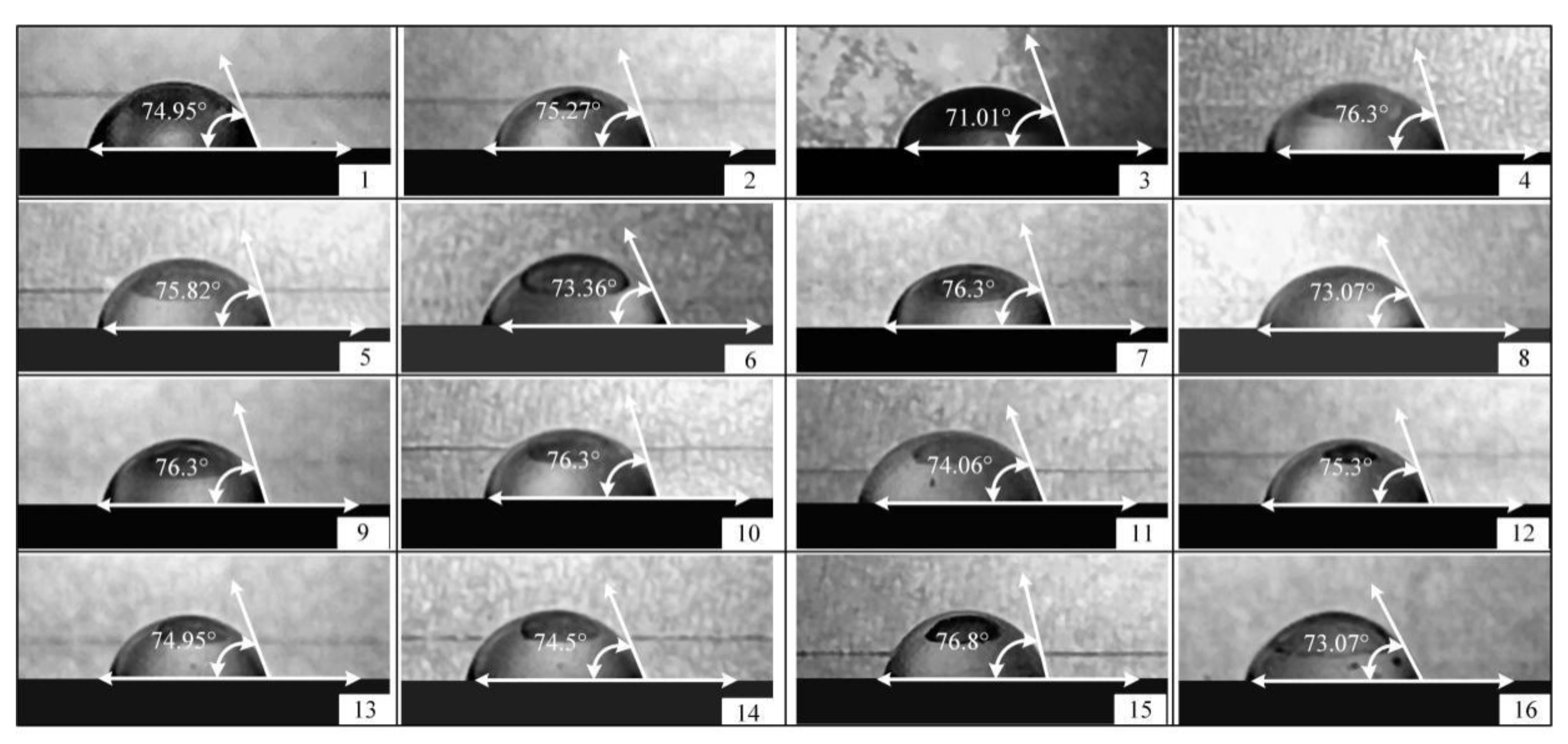
2.1. Contact Angle Measurement
2.1.1. Range Analysis of the Experiment Data
2.1.2. Variance Analysis of Experiment Data
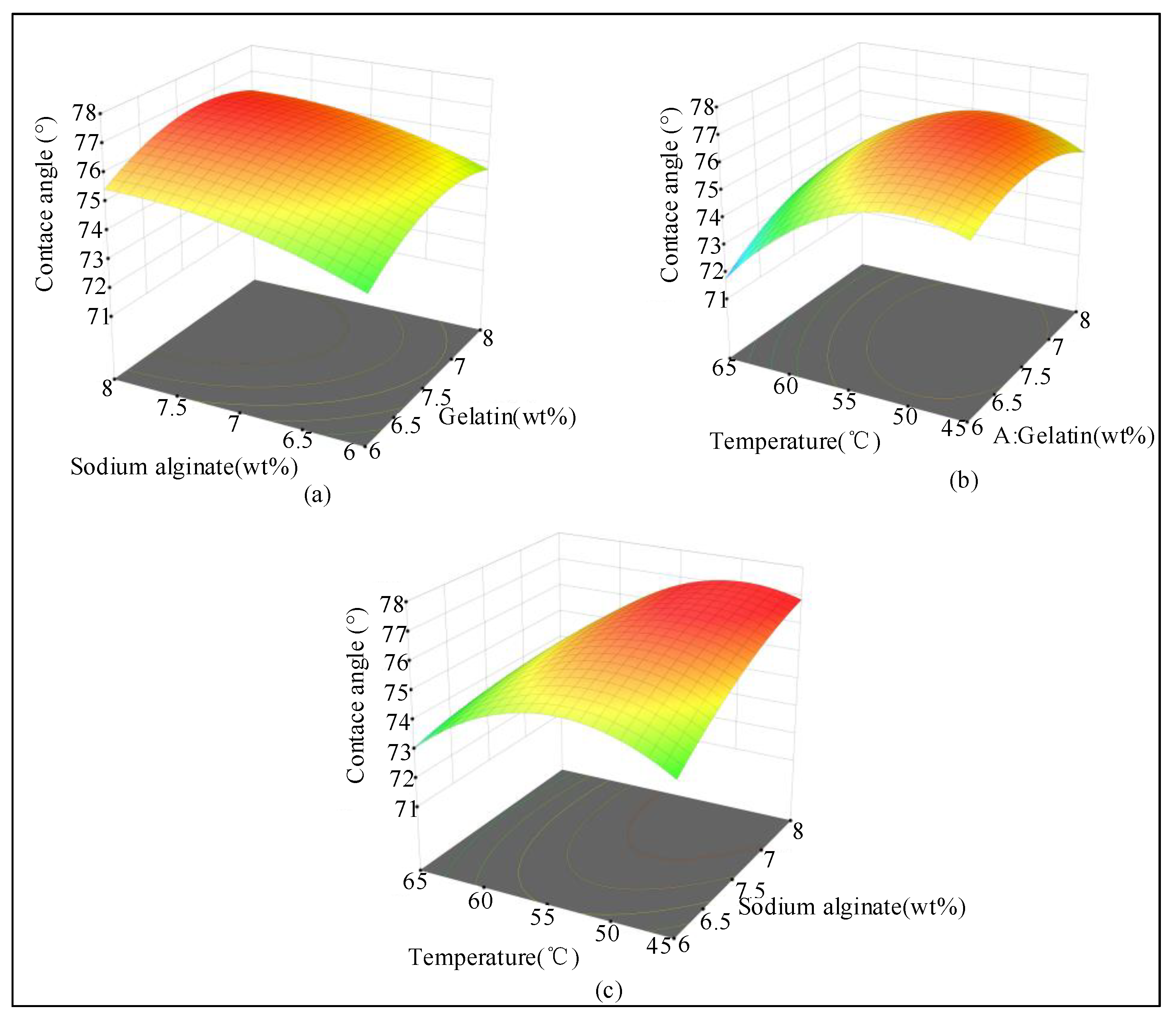
2.1.3. Response Surface Analysis of the Experiment Data
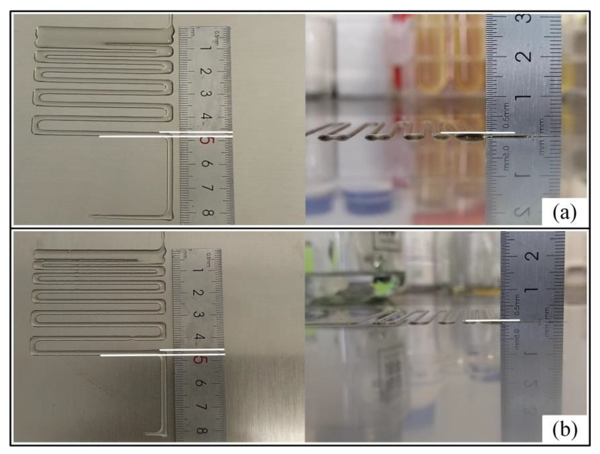
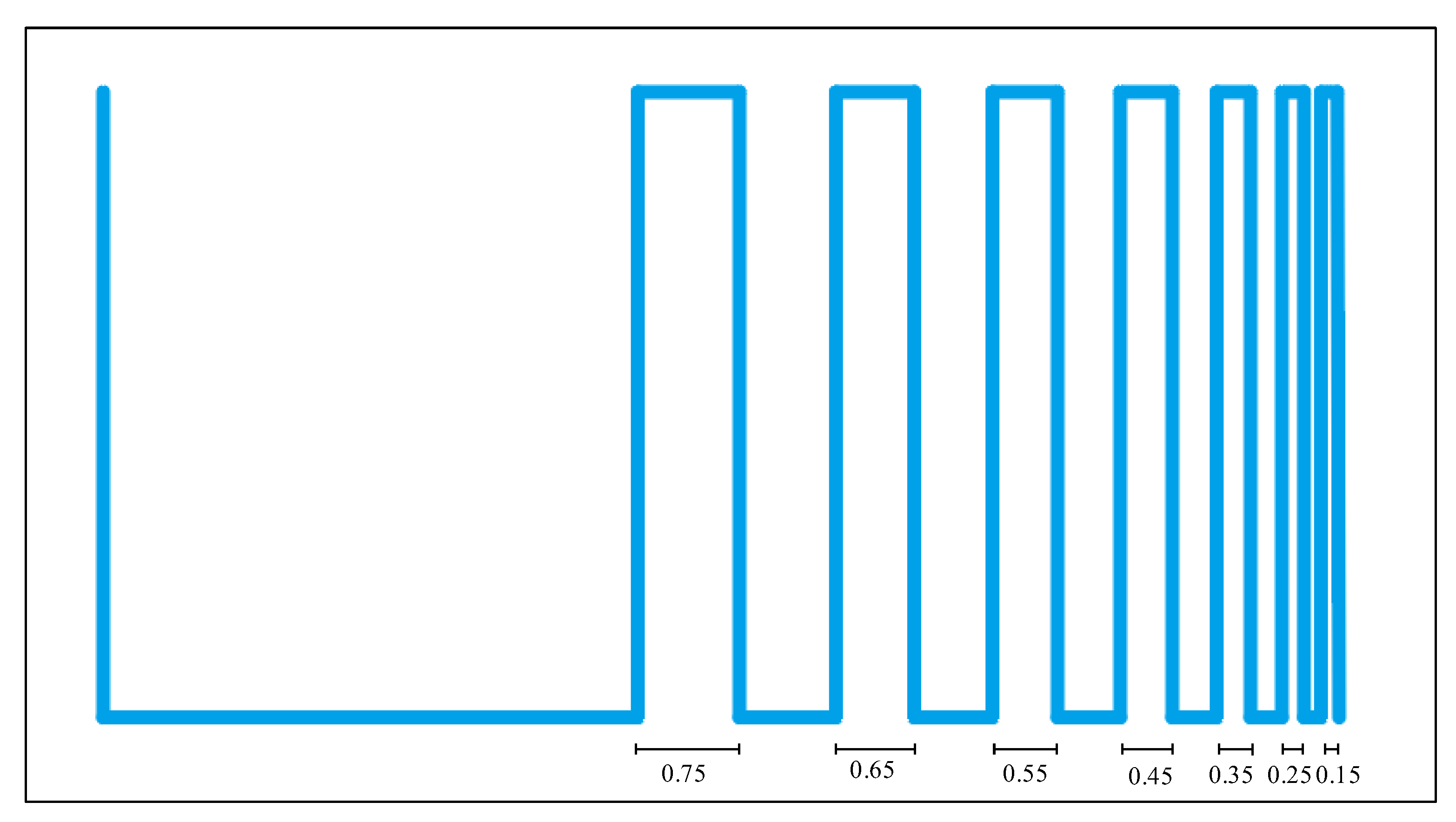
2.2. Gradient Line Analysis
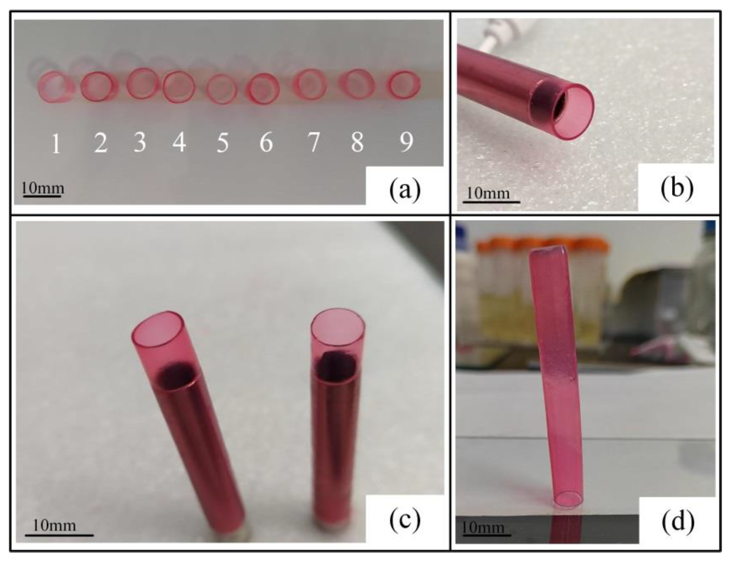
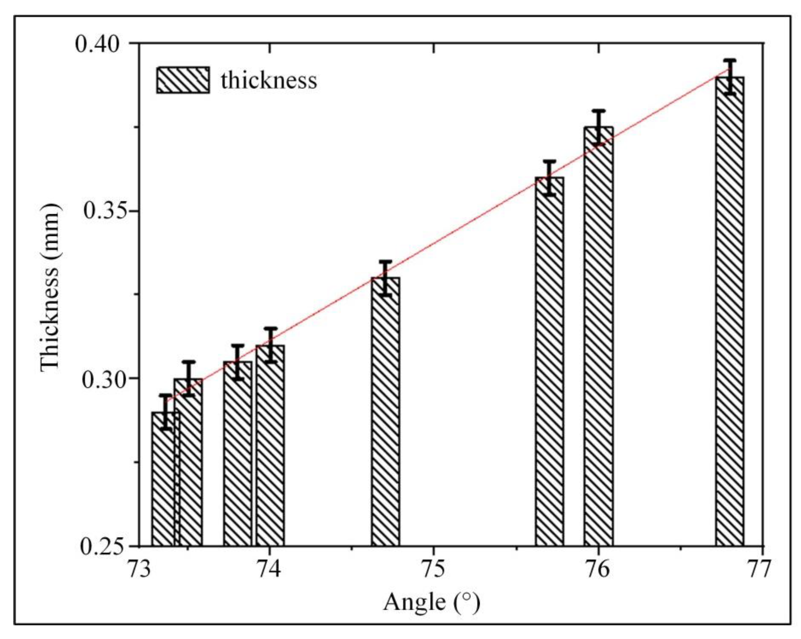
2.3. Analysis of Vessel Wall Thickness
3. Discussion
4. Materials and Methodology
4.1. Materials
4.2. Methodology
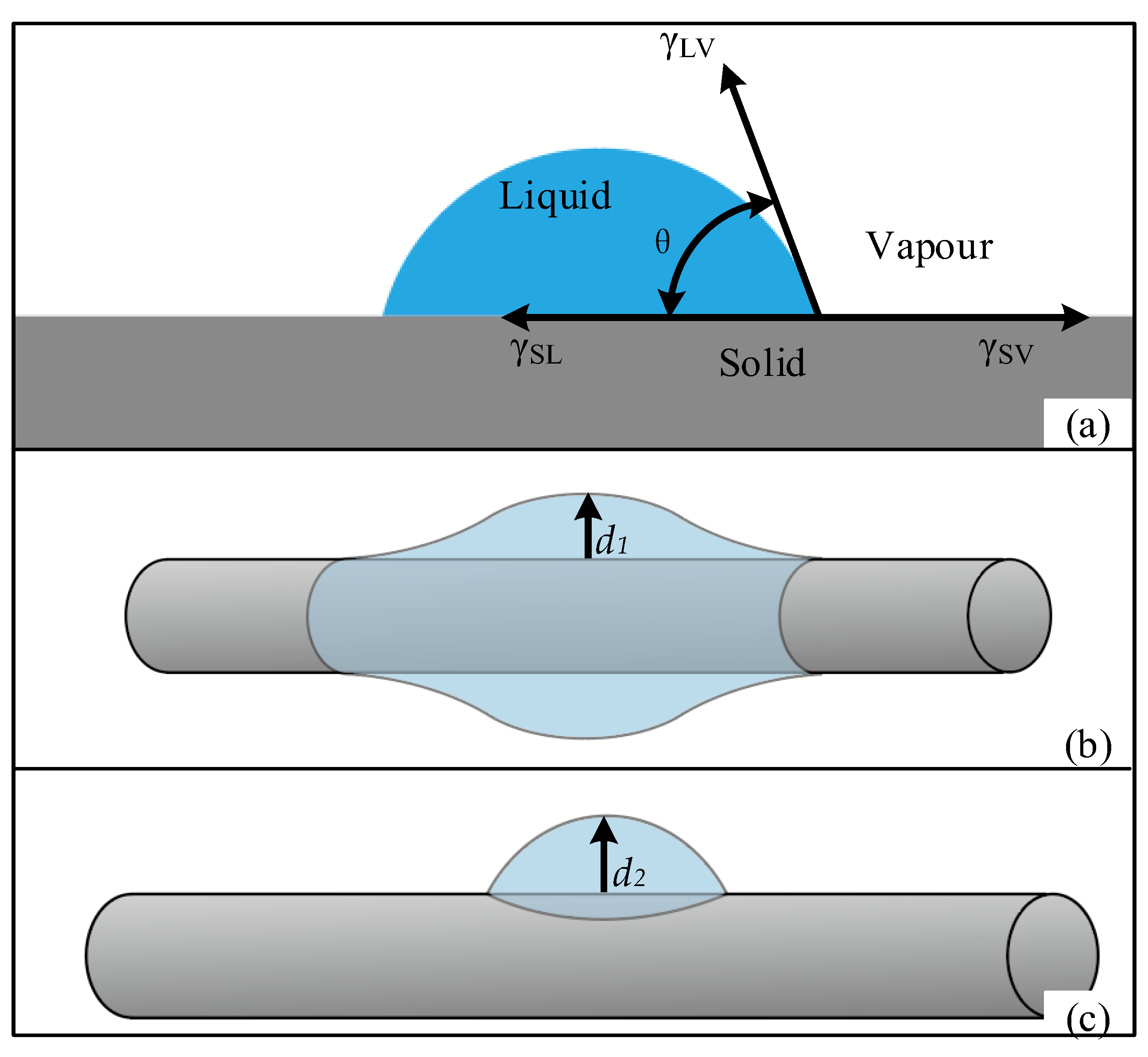
4.2.1. Contact Angle Experiment
- (1)
- Contact angle
- (2)
- Contact angle analysis
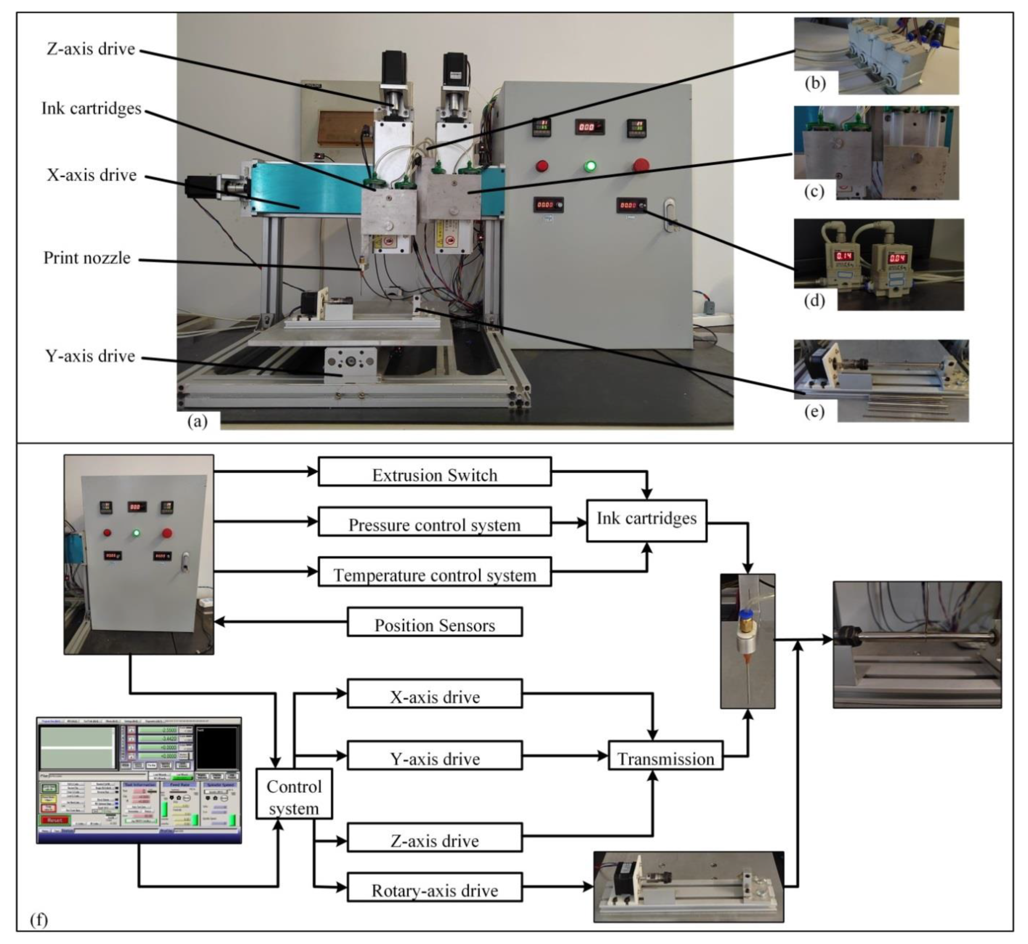
4.2.2. 3D Bioprinting
- (1)
- Multi-nozzle 3D bioprinter
- (2)
- Gradient line printing
- (3)
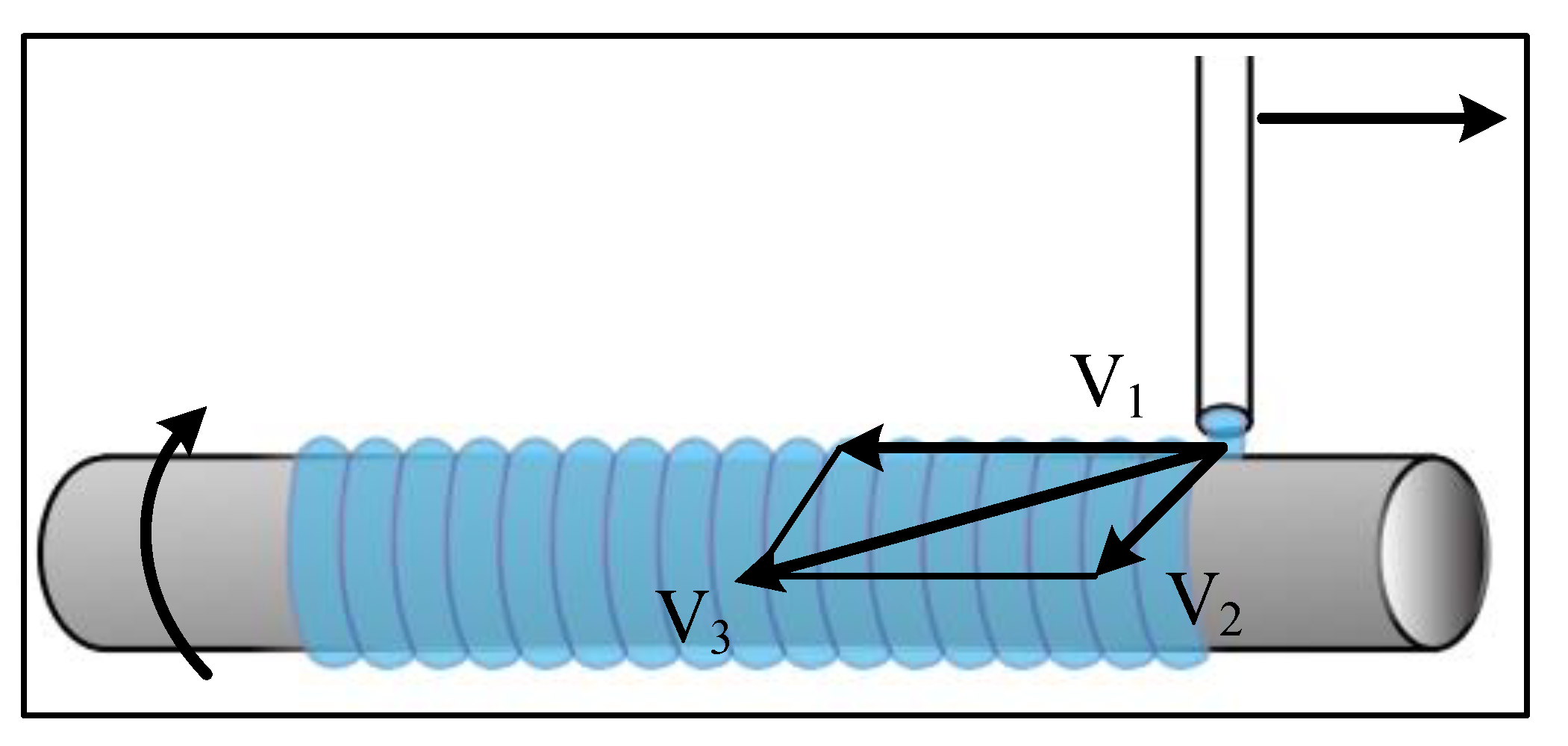
- Artificial blood vessel printing
5. Conclusions
Author Contributions
Funding
Institutional Review Board Statement
Informed Consent Statement
Data Availability Statement
Conflicts of Interest
References
- Martins, B.; Ferreira, D.; Neto, C.; Abelha, A.; Machado, J. Data Mining for Cardiovascular Disease Prediction. J. Med. Syst. 2021, 45, 6. [Google Scholar] [CrossRef]
- Xie, Y.; Xu, E.; Bowe, B.; Al-Aly, Z. Long-term cardiovascular outcomes of COVID-19. Nat. Med. 2022, 28, 583–590. [Google Scholar] [CrossRef]
- Liu, Y. New Method for Preparing Small-Caliber Artificial Blood Vessel with Controllable Microstructure on the Inner Wall Based on Additive Material Composite Molding. Micromachines 2021, 12, 1312. [Google Scholar] [CrossRef]
- Michele, C.; Paolo, M. Current Strategies for the Manufacture of Small Size Tissue Engineering Vascular Grafts. Front. Bioeng. Biotechnol. 2018, 6, 41. [Google Scholar]
- Sashka; Dimitrievska; Laura, E.; Niklason. Historical Perspective and Future Direction of Blood Vessel Developments. Cold Spring Harb. Perspect. Med. 2017, 8, a025742. [Google Scholar]
- Cao, X.; Maharjan, S.; Ashfaq, R.; Shin, J.; Zhang, Y.S. Bioprinting of Small-Diameter Blood Vessels. Engineering 2021, 7, 832–844. [Google Scholar] [CrossRef]
- Arai, K.; Tsukamoto, Y.; Yoshida, H.; Sanae, H.; Nakamura, M. The development of cell-adhesive hydrogel for 3D printing. Int. J. Bioprint. 2016, 2, 153–162. [Google Scholar] [CrossRef]
- Jmu, A.; Acja, B. Hydrogel-based 3D bioprinting: A comprehensive review on cell-laden hydrogels, bioink formulations, and future perspectives. Appl. Mater. Today 2020, 18, 100479. [Google Scholar]
- Leu Alexa, R.; Iovu, H.; Ghitman, J.; Serafim, A.; Stavarache, C.; Marin, M.M.; Ianchis, R. 3D-printed gelatin methacryloyl-based scaffolds with potential application in tissue engineering. Polymers 2021, 13, 727. [Google Scholar] [CrossRef] [PubMed]
- Celikkin, N.; Mastrogiacomo, S.; Dou, W.; Heerschap, A.; Oosterwijk, E.; Walboomers, X.F.; Święszkowski, W. In vitro and in vivo assessment of a 3D printable gelatin methacrylate hydrogel for bone regeneration applications. J. Biomed. Mater. Res. Part B Appl. Biomater. 2022, 110, 2133–2145. [Google Scholar] [CrossRef] [PubMed]
- Chen, S.; Jang, T.S.; Pan, H.M.; Jung, H.D.; Sia, M.W.; Xie, S.; Hang, Y.; Chong, S.K.M.; Wang, D.; Song, J. 3D Freeform Printing of Nanocomposite Hydrogels through in situ Precipitation in Reactive Viscous Fluid. Int. J. Bioprint. 2020, 6, 258. [Google Scholar] [PubMed]
- Li, H.; Liu, S.; Li, L. Rheological study on 3D printability of alginate hydrogel and effect of graphene oxide. Int. J. Bioprint. 2016, 2, 13. [Google Scholar] [CrossRef]
- Wei, L.N.; Yeong, W.Y.; Naing, M.W. Polyelectrolyte gelatin-chitosan hydrogel optimized for 3D bioprinting in skin tissue engineering. Int. J. Bioprint. 2016, 2, 10. [Google Scholar]
- Yang, B.; Liu, T.; Gao, G.; Zhang, X.; Wu, B. Fabrication of 3D GelMA Scaffolds Using Agarose Microgel Embedded Printing. Micromachines 2022, 13, 469. [Google Scholar] [CrossRef] [PubMed]
- Chakraborty, J.; Ghosh, S. Cellular Proliferation, Self-Assembly, and Modulation of Signaling Pathways in Silk Fibroin Gelatin-Based 3D Bioprinted Constructs. ACS Appl. Bio Mater. 2020, 3, 8309–8320. [Google Scholar] [CrossRef]
- Echave, M.C.; Sánchez, P.; Pedraz, J.L.; Orive, G. Progress of gelatin-based 3D approaches for bone regeneration. J. Drug Deliv. Sci. Technol. 2017, 42, 63–74. [Google Scholar] [CrossRef]
- Kakarla, A.B.; Turek, I.; Kong, C.; Irving, H. Printable gelatin, alginate and boron nitride nanotubes hydrogel-based ink for 3D bioprinting and tissue engineering applications. Mater. Des. 2021, 213, 110362. [Google Scholar] [CrossRef]
- Iovu, H. 3D Printing of Alginate-Natural Clay Hydrogel-Based Nanocomposites. Gels 2021, 7, 211. [Google Scholar] [CrossRef]
- Gelinsky, M. Biopolymer hydrogel bioinks—ScienceDirect. In 3D Bioprinting for Reconstructive Surgery; Woodhead Publishing: Sawston, UK, 2018; pp. 125–136. [Google Scholar]
- Hussin, M.S.F.; Mohd Serah, A.; Azlan, K.A.; Abdullah, H.Z.; Idris, M.I.; Ghazali, I.; Mohd Shariff, A.H.; Huda, N.; Zakaria, A.A. A bibliometric analysis of the global trend of using alginate, gelatine, and hydroxyapatite for bone tissue regeneration applications. Polymers 2021, 13, 647. [Google Scholar] [CrossRef]
- Kolan, K.C.; Semon, J.A.; Bromet, B.; Day, D.E.; Leu, M.C. Bioprinting with human stem cell-laden alginate-gelatin bioink and bioactive glass for tissue engineering. Int. J. Bioprint. 2019, 5, 204. [Google Scholar] [CrossRef] [PubMed]
- Curti, F.; Drăgușin, D.M.; Serafim, A.; Iovu, H.; Stancu, I.C. Development of thick paste-like inks based on superconcentrated gelatin/alginate for 3D printing of scaffolds with shape fidelity and stability. Mater. Sci. Eng. C 2021, 122, 111866. [Google Scholar] [CrossRef] [PubMed]
- Han, X.; Huang, C.; Wang, Z.; Li, S.; Chen, Z.; Huang, J.; Liu, H.; Yan, Y. Fabrication of hydrogels with adjustable mechanical properties through 3D cell-laden printing technology. Colloids Surf. A Physicochem. Eng. Asp. 2022, 646, 128980. [Google Scholar] [CrossRef]
- Liu, H.; Yang, X.; Cheng, X.; Zhao, G.; Zheng, G.; Li, X.; Dong, R. Theoretical and experimental research on multi-layer vessel-like structure printing based on 3D bio-printing technology. Micromachines 2021, 12, 1517. [Google Scholar] [CrossRef] [PubMed]
- Iranmanesh, P.; Gowdini, M.; Khademi, A.; Dehghani, M.; Latifi, M.; Alsaadi, N.; Hemati, M.; Mohammadi, R.; Saber-Samandari, S.; Toghraie, D.; et al. Bioprinting of three-dimensional scaffold based on alginate-gelatin as soft and hard tissue regeneration. J. Mater. Res. Technol. 2021, 14, 2853–2864. [Google Scholar] [CrossRef]
- Wang, H.J.; Mao, Q.Y.; Feng, G.; Liu, C.; Yang, M.Z.; Hao, M.F.; Meng, Z.F.; Li, S.M.; Zhang, Y.P.; Wang, J.Y. 3D printing of multi-functional artificial conduits against acute thrombosis and clinical infection. Compos. Part B Eng. 2022, 230, 109497. [Google Scholar] [CrossRef]
- Liu, Y.; Zhang, Y.; An, Z.; Zhao, H.; Zhang, L.; Cao, Y.; Mansoorianfar, M.; Liu, X.; Pei, R. Slide-Ring Structure-Based Double-Network Hydrogel with Enhanced Stretchability and Toughness for 3D-Bio-Printing and Its Potential Application as Artificial Small-Diameter Blood Vessels. ACS Appl. Bio Mater. 2021, 4, 8597–8606. [Google Scholar] [CrossRef] [PubMed]
- Dobos, A.; Gantner, F.; Markovic, M.; Van Hoorick, J.; Tytgat, L.; Van Vlierberghe, S.; Ovsianikov, A. On-chip high-definition bioprinting of microvascular structures. Biofabrication 2020, 13, 015016. [Google Scholar] [CrossRef] [PubMed]
- Millik, S.C.; Dostie, A.M.; Karis, D.G.; Smith, P.T.; McKenna, M.; Chan, N.; Curtis, C.D.; Nance, E.; Theberge, A.B.; Nelson, A. 3D printed coaxial nozzles for the extrusion of hydrogel tubes toward modeling vascular endothelium. Biofabrication 2019, 11, 045009. [Google Scholar] [CrossRef] [PubMed]
- Kucukgul, C.; Ozler, B.; Karakas, H.E.; Gozuacik, D.; Koc, B. 3D Hybrid Bioprinting of Macrovascular Structures. Procedia Eng. 2013, 59, 183–192. [Google Scholar] [CrossRef]
- Di Giuseppe, M.; Law, N.; Webb, B.; Macrae, R.A.; Liew, L.J.; Sercombe, T.B.; Dilley, R.J.; Doyle, B.J. Mechanical behaviour of alginate-gelatin hydrogels for 3D bioprinting. J. Mech. Behav. Biomed. Mater. 2018, 79, 150–157. [Google Scholar] [CrossRef] [PubMed]


| Orthogonal Experiment | Gelatin (wt%) | Sodium Alginate (wt%) | Temperature (°C) | Contact Angle (°) |
|---|---|---|---|---|
| 1 | 8 | 6 | 55 | 74.95 |
| 2 | 6 | 8 | 55 | 75.27 |
| 3 | 6 | 7 | 65 | 71.01 |
| 4 | 7 | 7 | 55 | 76.3 |
| 5 | 8 | 7 | 45 | 75.82 |
| 6 | 8 | 7 | 65 | 73.36 |
| 7 | 7 | 7 | 55 | 76.3 |
| 8 | 7 | 6 | 65 | 73.07 |
| 9 | 7 | 7 | 55 | 76.3 |
| 10 | 7 | 7 | 55 | 76.3 |
| 11 | 7 | 8 | 65 | 74.06 |
| 12 | 6 | 7 | 45 | 75.3 |
| 13 | 8 | 8 | 55 | 74.95 |
| 14 | 6 | 6 | 55 | 74.5 |
| 15 | 7 | 8 | 45 | 76.8 |
| 16 | 7 | 6 | 45 | 73.07 |
| Experiment Results | Gelatin | Sodium Alginate | Temperature |
|---|---|---|---|
| K1 | 296.08 | 295.59 | 300.99 |
| K2 | 678.50 | 676.99 | 681.17 |
| K3 | 299.08 | 301.08 | 291.5 |
| k1 | 74.02 | 73.90 | 75.25 |
| k2 | 75.29 | 75.22 | 75.68 |
| k3 | 74.77 | 75.27 | 72.87 |
| Range R | 1.36 | 1.37 | 2.81 |
| Major factor → Minor factor | Temperature → Sodium alginate → Gelatin | ||
| Variance Analysis | Variance Source | Freedom | Square Sum | Mean Square | F Value | p Value | Significance |
|---|---|---|---|---|---|---|---|
| 1 | A-Gelatin | 1 | 1.67 | 1.67 | 2.98 | 0.1282 | Significant |
| 2 | B-Sodium alginate | 1 | 4.71 | 4.71 | 8.42 | 0.0229 | Extremely significant |
| 3 | C-Temperature | 1 | 11.26 | 11.26 | 20.12 | 0.0028 | Extremely significant |
| 4 | AB | 1 | 0.0036 | 0.0036 | 0.0064 | 0.9383 | Non-significant |
| 5 | AC | 1 | 0.8372 | 0.8372 | 1.5 | 0.2608 | Significant |
| 6 | BC | 1 | 1.88 | 1.88 | 3.35 | 0.1097 | Significant |
| 7 | A2 | 1 | 2.69 | 2.69 | 4.8 | 0.0646 | Significant |
| 8 | B2 | 1 | 0.7472 | 0.7472 | 1.34 | 0.2858 | Significant |
| 9 | C2 | 1 | 11.17 | 11.17 | 19.96 | 0.0029 | Extremely significant |
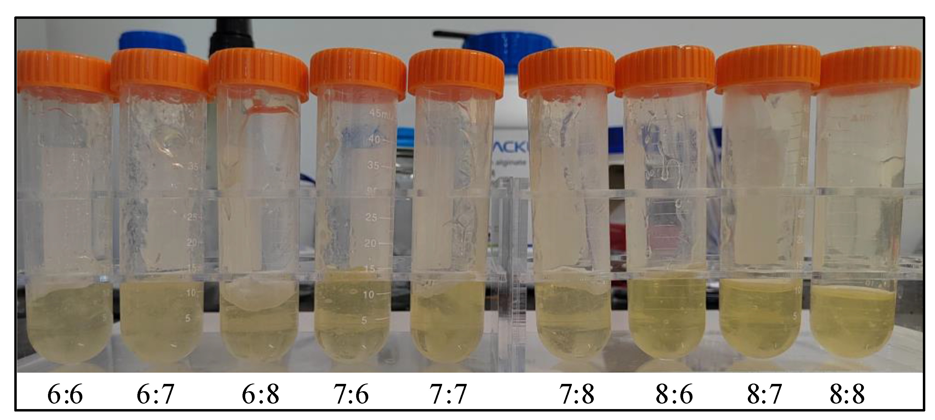
| Sample Serial Number | Quality Percentage (wt%) | |
|---|---|---|
| Gelatin | Sodium Alginate | |
| 1 | 6 | 6 |
| 2 | 6 | 7 |
| 3 | 6 | 8 |
| 4 | 7 | 6 |
| 5 | 7 | 7 |
| 6 | 7 | 8 |
| 7 | 8 | 6 |
| 8 | 8 | 7 |
| 9 | 8 | 8 |
| Sample Serial Number | Gelatin (wt%) | Sodium Alginate (wt%) | Temperature (°C) |
|---|---|---|---|
| 1 | 6 | 6 | 45 |
| 2 | 6 | 7 | 55 |
| 3 | 6 | 8 | 65 |
| 4 | 7 | 6 | 55 |
| 5 | 7 | 7 | 65 |
| 6 | 7 | 8 | 45 |
| 7 | 8 | 6 | 65 |
| 8 | 8 | 7 | 45 |
| 9 | 8 | 8 | 55 |
Publisher’s Note: MDPI stays neutral with regard to jurisdictional claims in published maps and institutional affiliations. |
© 2022 by the authors. Licensee MDPI, Basel, Switzerland. This article is an open access article distributed under the terms and conditions of the Creative Commons Attribution (CC BY) license (https://creativecommons.org/licenses/by/4.0/).
Share and Cite
Jin, W.; Liu, H.; Li, Z.; Nie, P.; Zhao, G.; Cheng, X.; Zheng, G.; Yang, X. Effect of Hydrogel Contact Angle on Wall Thickness of Artificial Blood Vessel. Int. J. Mol. Sci. 2022, 23, 11114. https://doi.org/10.3390/ijms231911114
Jin W, Liu H, Li Z, Nie P, Zhao G, Cheng X, Zheng G, Yang X. Effect of Hydrogel Contact Angle on Wall Thickness of Artificial Blood Vessel. International Journal of Molecular Sciences. 2022; 23(19):11114. https://doi.org/10.3390/ijms231911114
Chicago/Turabian StyleJin, Wenyu, Huanbao Liu, Zihan Li, Ping Nie, Guangxi Zhao, Xiang Cheng, Guangming Zheng, and Xianhai Yang. 2022. "Effect of Hydrogel Contact Angle on Wall Thickness of Artificial Blood Vessel" International Journal of Molecular Sciences 23, no. 19: 11114. https://doi.org/10.3390/ijms231911114
APA StyleJin, W., Liu, H., Li, Z., Nie, P., Zhao, G., Cheng, X., Zheng, G., & Yang, X. (2022). Effect of Hydrogel Contact Angle on Wall Thickness of Artificial Blood Vessel. International Journal of Molecular Sciences, 23(19), 11114. https://doi.org/10.3390/ijms231911114