
A Review of Microfluidic Experimental Designs for Nanoparticle Synthesis


Abstract
:1. Introduction
2. Nanoparticle Synthesis
2.1. Continuous Flow
2.2. Droplet-Based and Segmented Flow
3. Mixing
4. Geometries
4.1. T-Type Microreactors
4.2. Y-Type Microreactors
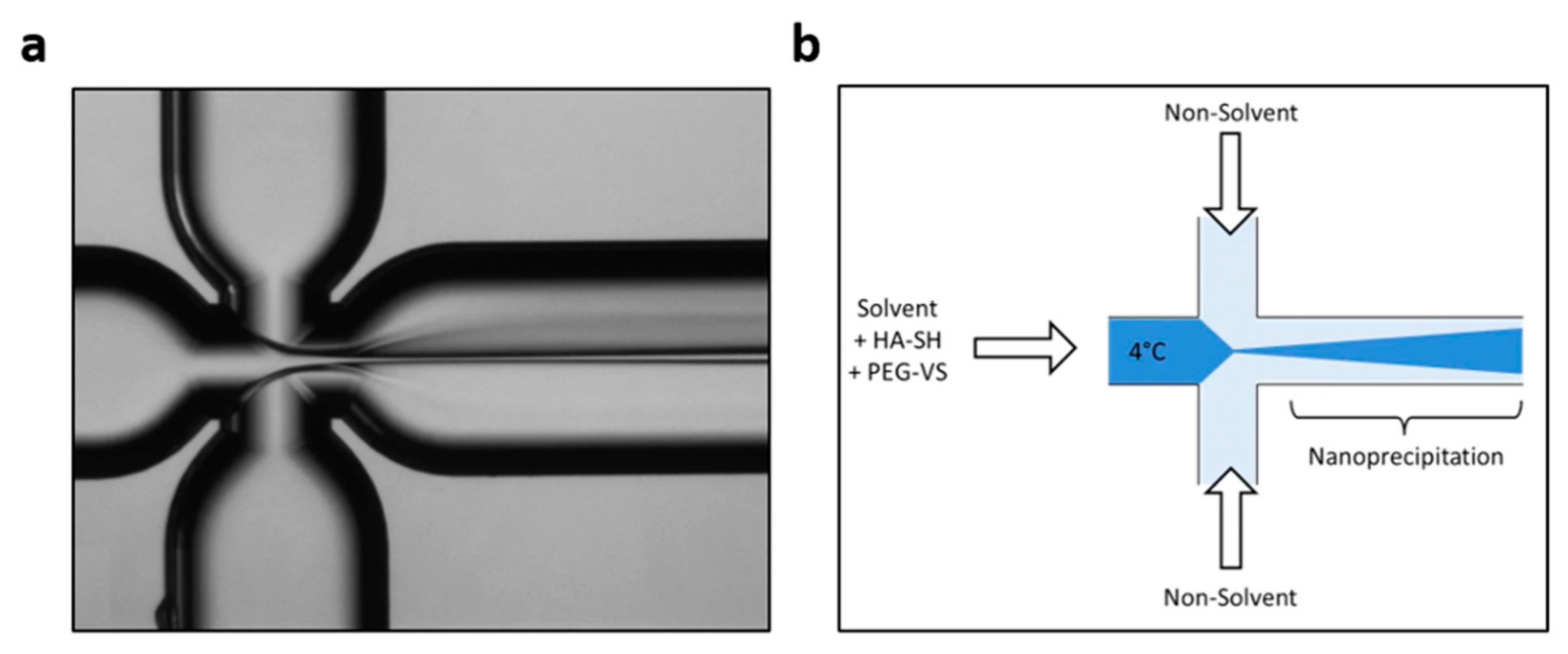
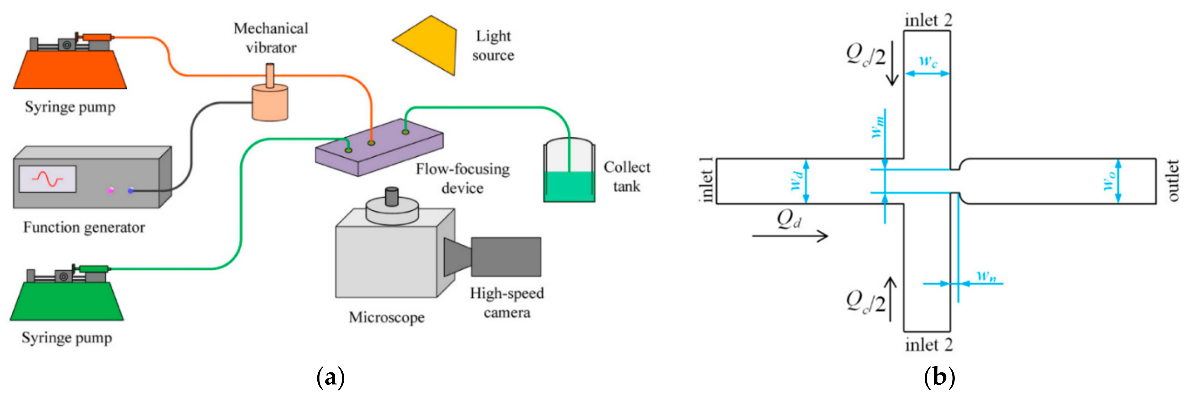
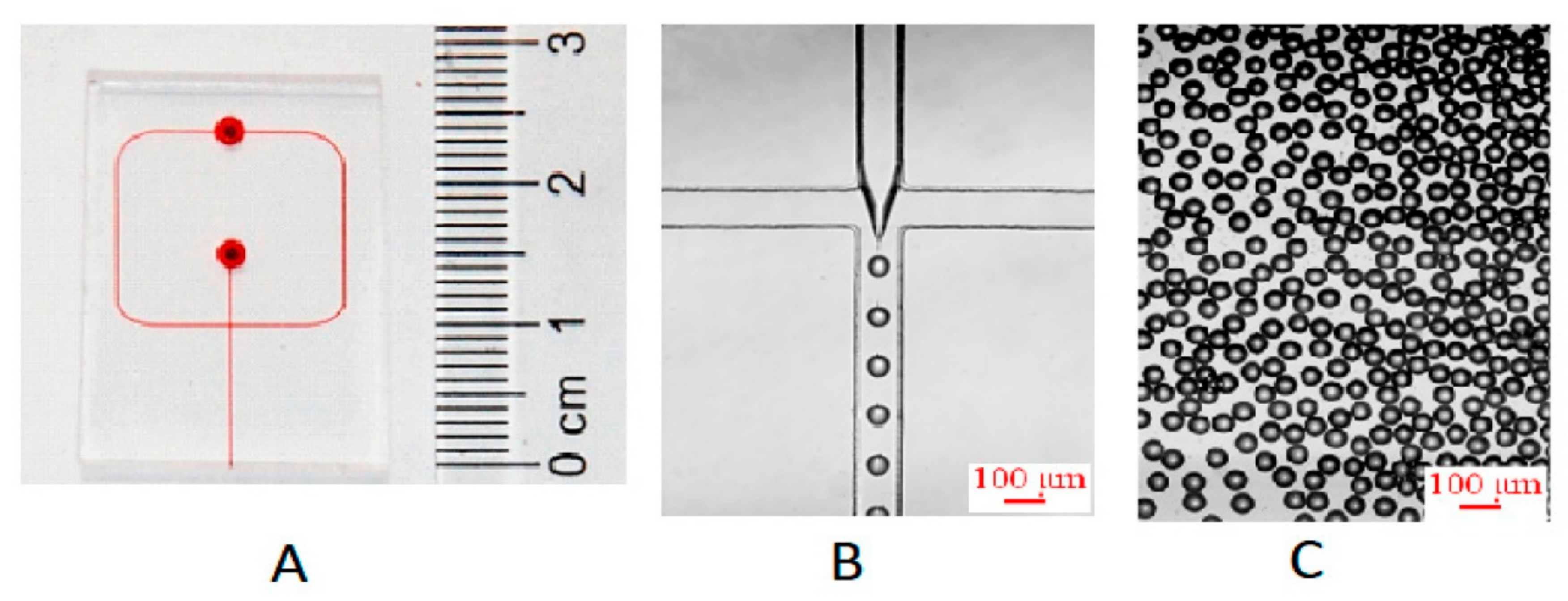
4.3. Flow-Focusing Microreactors
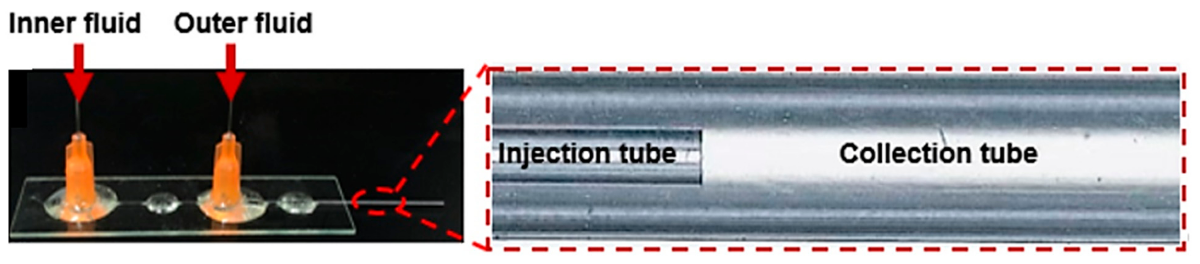
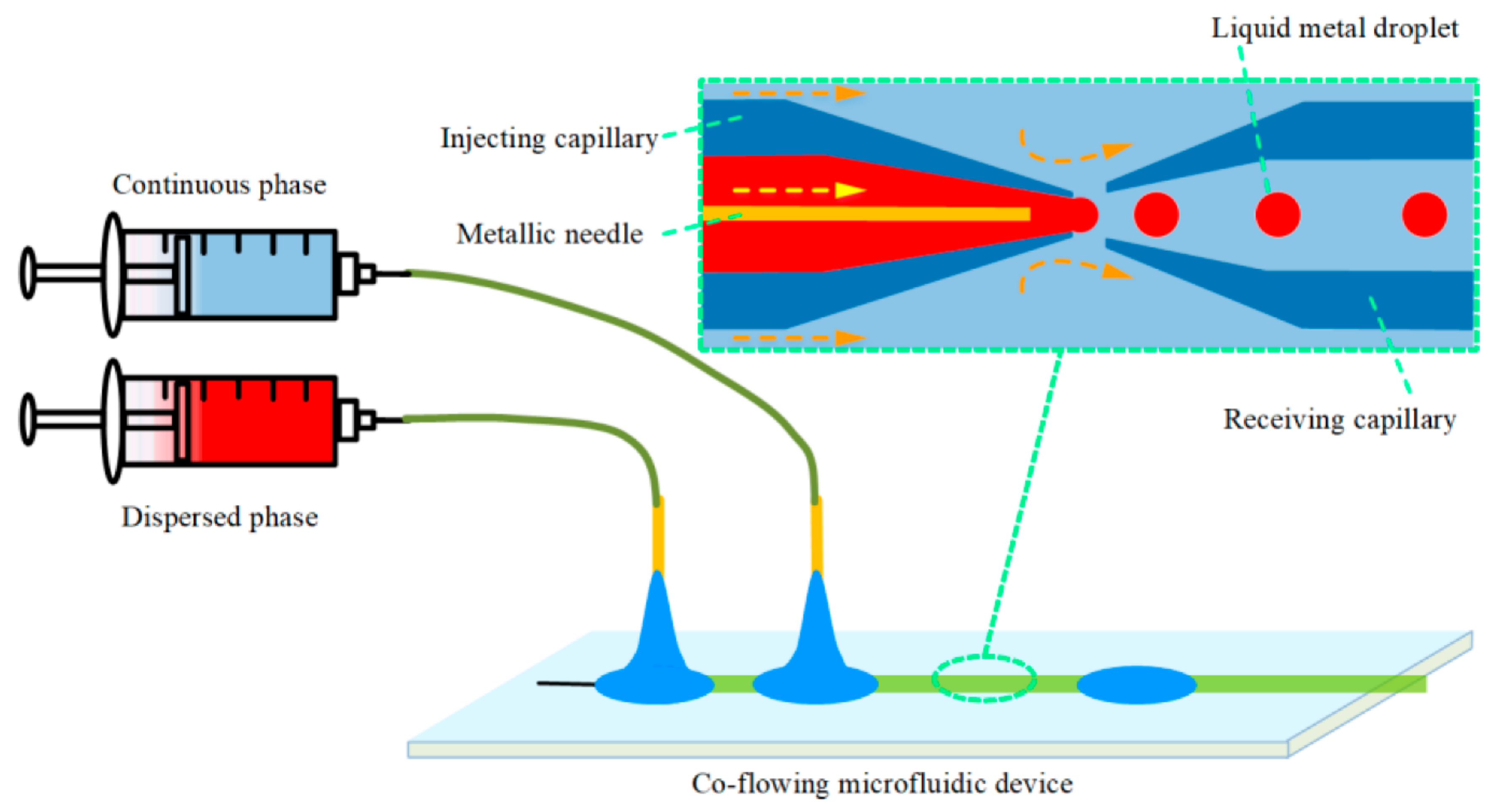
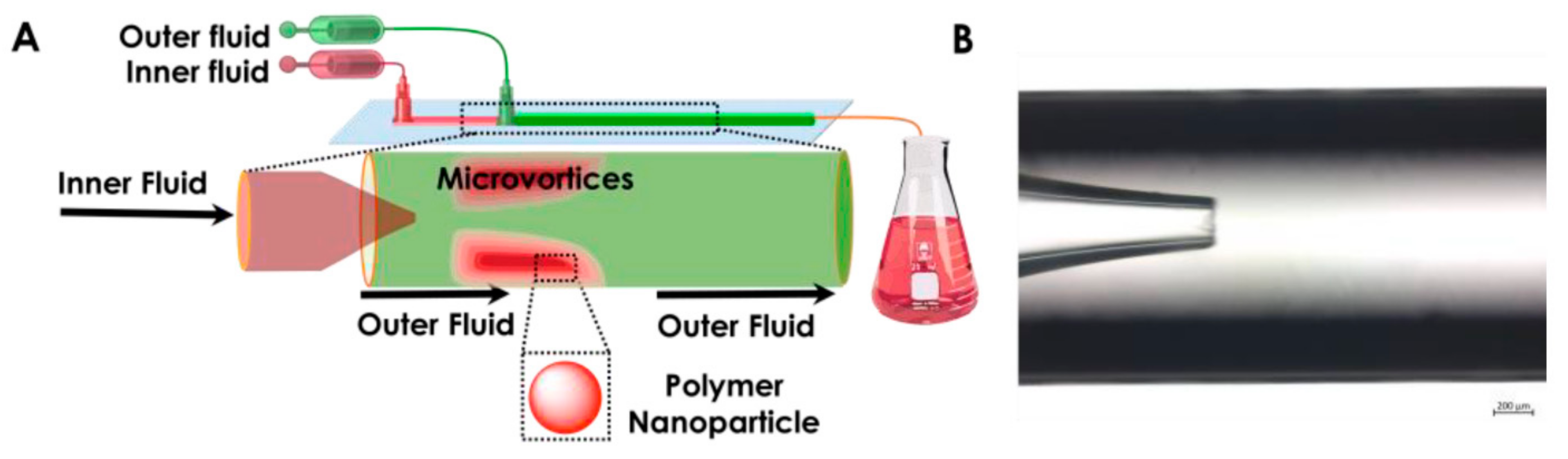
4.4. Co-Flowing Microreactors
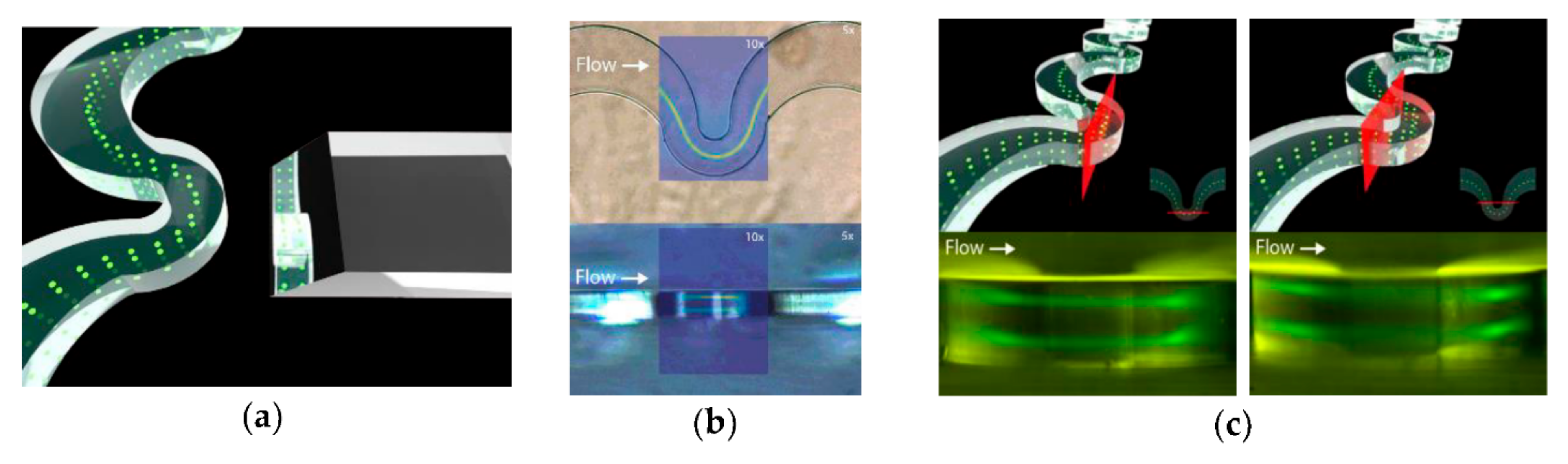
4.5. S-Shaped Microchannels
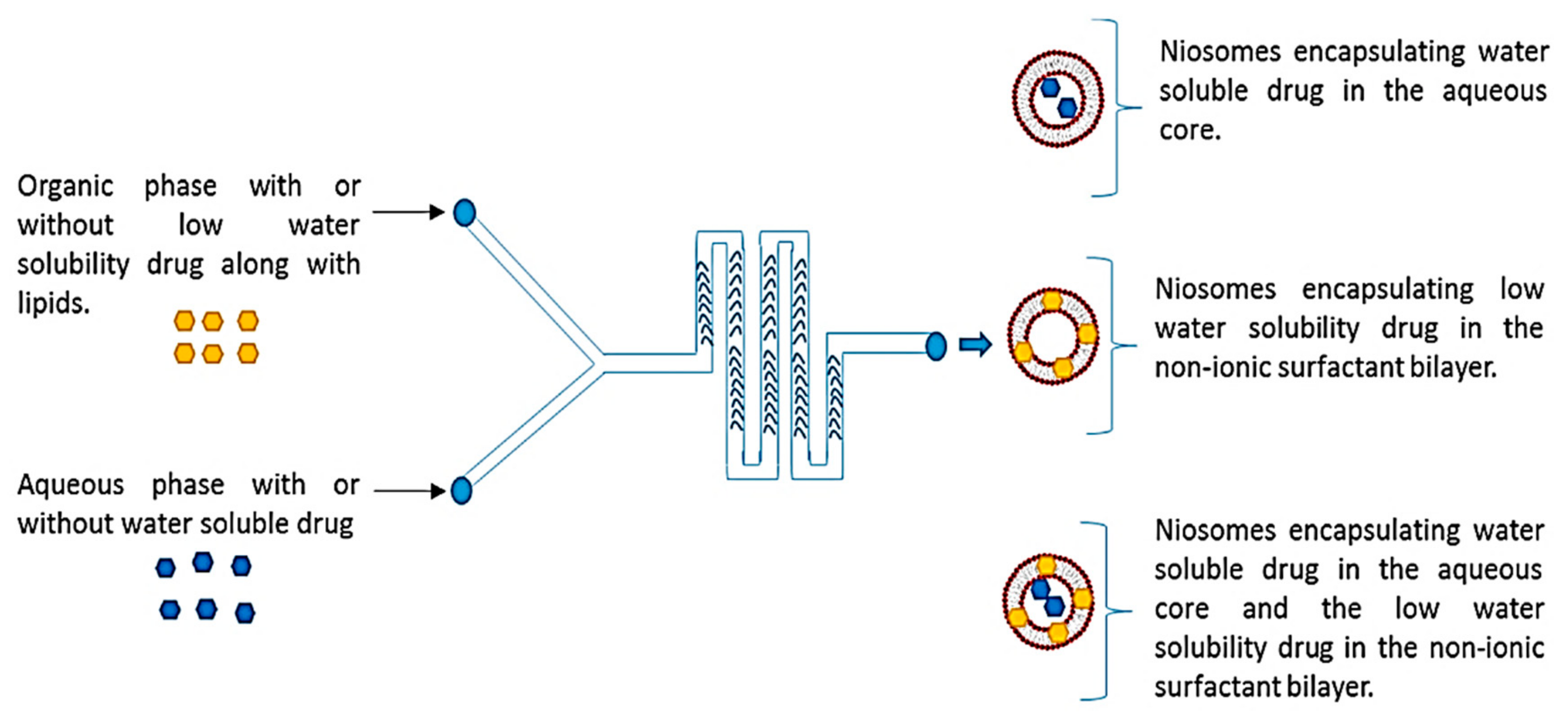
4.6. Staggered Herringbone Micromixer
4.7. Other Geometries
4.8. Combined Geometries
4.9. Three-Dimensional Printed Configurations
4.10. Geometries Overview
5. Conclusions and Future Perspectives
Author Contributions
Funding
Institutional Review Board Statement
Informed Consent Statement
Data Availability Statement
Conflicts of Interest
References
- Damiati, S.; Kompella, U.B.; Damiati, S.A.; Kodzius, R. Microfluidic Devices for Drug Delivery Systems and Drug Screening. Genes 2018, 9, 103. [Google Scholar] [CrossRef] [PubMed] [Green Version]
- Gonzalez, G.; Roppolo, I.; Pirri, C.F.; Chiappone, A. Current and emerging trends in polymeric 3D printed microfluidic devices. Addit. Manuf. 2022, 55, 102867. [Google Scholar] [CrossRef]
- Tian, F.; Cai, L.; Liu, C.; Sun, J. Microfluidic technologies for nanoparticle formation. Lab Chip 2022, 22, 512–529. [Google Scholar] [CrossRef]
- Zhou, Y.; Wang, D.; Kang, X.; Zhang, D.; Dou, X.; Wang, X.; Guo, G. A scalable synthesis of ternary nanocatalysts for a high-efficiency electrooxidation catalysis by microfluidics. Nanoscale 2020, 12, 12647–12654. [Google Scholar] [CrossRef] [PubMed]
- Kung, C.-T.; Gao, H.; Lee, C.-Y.; Wang, Y.-N.; Dong, W.; Ko, C.-H.; Wang, G.; Fu, L.-M. Microfluidic synthesis control technology and its application in drug delivery, bioimaging, biosensing, environmental analysis and cell analysis. Chem. Eng. J. 2020, 399, 125748. [Google Scholar] [CrossRef]
- Ballacchino, G.; Weaver, E.; Mathew, E.; Dorati, R.; Genta, I.; Conti, B.; Lamprou, D.A. Manufacturing of 3D-Printed Microfluidic Devices for the Synthesis of Drug-Loaded Liposomal Formulations. Int. J. Mol. Sci. 2021, 22, 8064. [Google Scholar] [CrossRef]
- Suryawanshi, P.L.; Gumfekar, S.P.; Bhanvase, B.A.; Sonawane, S.H.; Pimplapure, M.S. A review on microreactors: Reactor fabrication, design, and cutting-edge applications. Chem. Eng. Sci. 2018, 189, 431–448. [Google Scholar] [CrossRef]
- Eş, I.; Montebugnoli, L.J.; Filippi, M.F.P.; Malfatti-Gasperini, A.A.; Radaic, A.; de Jesus, M.B.; de la Torre, L.G. High-throughput conventional and stealth cationic liposome synthesis using a chaotic advection-based microfluidic device combined with a centrifugal vacuum concentrator. Chem. Eng. J. 2020, 382, 122821. [Google Scholar] [CrossRef]
- Chen, X. Topology optimization of microfluidics—A review. Microchem. J. 2016, 127, 52–61. [Google Scholar] [CrossRef]
- Wong, V.-L.; Ng, C.-A.I.; Teo, L.-R.I.; Lee, C.-W. Microfluidic Synthesis of Functional Materials as Potential Sorbents for Water Remediation and Resource Recovery. In Advances in Microfluidic Technologies for Energy and Environmental Applications; IntechOpen: London, UK, 2020. [Google Scholar]
- Mancera-Andrade, E.I.; Parsaeimehr, A.; Arevalo-Gallegos, A.; Ascencio-Favela, G. Microfluidics technology for drug delivery: A review. Front. Biosci. (Elite Ed.) 2018, 10, 74–91. [Google Scholar]
- Sengupta, P.; Khanra, K.; Roychowdhury, A.; Datta, P. Lab-on-a-chip sensing devices for biomedical applications. In Bioelectronics and Medical Devices; Woodhead Publishing: Sawston, UK, 2019. [Google Scholar]
- Rivet, C.; Lee, H.; Hirsch, A.; Hamilton, S.; Lu, H. Microfluidics for medical diagnostics and biosensors. Chem. Eng. Sci. 2011, 66, 1490–1507. [Google Scholar] [CrossRef]
- Zhao, C.-X.; He, L.; Qiao, S.Z.; Middelberg, A.P.J. Nanoparticle synthesis in microreactors. Chem. Eng. Sci. 2011, 66, 1463–1479. [Google Scholar] [CrossRef]
- Bally, F.; Serra, C.A.; Hessel, V.; Hadziioannou, G. Micromixer-assisted polymerization processes. Chem. Eng. Sci. 2011, 66, 1449–1462. [Google Scholar] [CrossRef]
- Olanrewaju, A.; Beaugrand, M.; Yafia, M.; Juncker, D. Capillary microfluidics in microchannels: From microfluidic networks to capillaric circuits. Lab Chip 2018, 18, 2323–2347. [Google Scholar] [CrossRef] [PubMed] [Green Version]
- Pan, L.-J.; Tu, J.-W.; Ma, H.-T.; Yang, Y.-J.; Tian, Z.-Q.; Pang, D.-W.; Zhang, Z.-L. Controllable synthesis of nanocrystals in droplet reactors. Lab Chip 2018, 18, 41–56. [Google Scholar] [CrossRef] [PubMed]
- Shrimal, P.; Jadeja, G.; Patel, S. A review on novel methodologies for drug nanoparticle preparation: Microfluidic approach. Chem. Eng. Res. Des. 2020, 153, 728–756. [Google Scholar] [CrossRef]
- Ma, J.; Lee, S.M.-Y.; Yi, C.; Li, C.-W. Controllable synthesis of functional nanoparticles by microfluidic platforms for biomedical applications—A review. Lab Chip 2017, 17, 209–226. [Google Scholar] [CrossRef]
- Hwang, J.; Cho, Y.H.; Park, M.S.; Kim, B.H. Microchannel Fabrication on Glass Materials for Microfluidic Devices. Int. J. Precis. Eng. Manuf. 2019, 20, 479–495. [Google Scholar] [CrossRef]
- Valencia, P.M.; Farokhzad, O.C.; Karnik, R.; Langer, R. Microfluidic technologies for accelerating the clinical translation of nanoparticles. Nat. Nanotechnol. 2012, 7, 623–629. [Google Scholar] [CrossRef] [Green Version]
- Cabeza, V.S. High and efficient production of nanomaterials by microfluidic reactor approaches. In Advances in Microfluidics–New Applications in Biology, Energy, and Materials Sciences; InTech: Rijeka, Croatia, 2016. [Google Scholar]
- Niculescu, A.-G.; Chircov, C.; Bîrcă, A.C.; Grumezescu, A.M. Nanomaterials Synthesis through Microfluidic Methods: An Updated Overview. Nanomaterials 2021, 11, 864. [Google Scholar] [CrossRef]
- Hamdallah, S.I.; Zoqlam, R.; Erfle, P.; Blyth, M.; Alkilany, A.M.; Dietzel, A.; Qi, S. Microfluidics for pharmaceutical nanoparticle fabrication: The truth and the myth. Int. J. Pharm. 2020, 584, 119408. [Google Scholar] [CrossRef]
- Liu, D.; Cito, S.; Zhang, Y.; Wang, C.-F.; Sikanen, T.M.; Santos, H.A. A Versatile and Robust Microfluidic Platform Toward High Throughput Synthesis of Homogeneous Nanoparticles with Tunable Properties. Adv. Mater. 2015, 27, 2298–2304. [Google Scholar] [CrossRef]
- Koryakina, I.G.; Afonicheva, P.K.; Arabuli, K.V.; Evstrapov, A.A.; Timin, A.S.; Zyuzin, M.V. Microfluidic synthesis of optically responsive materials for nano- and biophotonics. Adv. Colloid Interface Sci. 2021, 298, 102548. [Google Scholar] [CrossRef] [PubMed]
- Makgwane, P.R.; Ray, S.S. Synthesis of Nanomaterials by Continuous-Flow Microfluidics: A Review. J. Nanosci. Nanotechnol. 2014, 14, 1338–1363. [Google Scholar] [CrossRef]
- Brivio, M.; Verboom, W.; Reinhoudt, D.N. Miniaturized continuous flow reaction vessels: Influence on chemical reactions. Lab Chip 2006, 6, 329–344. [Google Scholar] [CrossRef]
- Jahn, A.; Reiner, J.E.; Vreeland, W.N.; DeVoe, D.L.; Locascio, L.E.; Gaitan, M. Preparation of nanoparticles by continuous-flow microfluidics. J. Nanopart. Res. 2008, 10, 925–934. [Google Scholar] [CrossRef]
- Xia, H.M.; Wu, J.W.; Zheng, J.J.; Zhang, J.; Wang, Z.P. Nonlinear microfluidics: Device physics, functions, and applications. Lab Chip 2021, 21, 1241–1268. [Google Scholar] [CrossRef] [PubMed]
- Tabeling, P. Recent progress in the physics of microfluidics and related biotechnological applications. Curr. Opin. Biotechnol. 2014, 25, 129–134. [Google Scholar] [CrossRef]
- Lee, D.; Kitahata, H.; Ito, H. Fabrication of Microparticles with Front–Back Asymmetric Shapes Using Anisotropic Gelation. Micromachines 2021, 12, 1121. [Google Scholar] [CrossRef]
- Ding, Y.; Howes, P.D.; deMello, A.J. Recent Advances in Droplet Microfluidics. Anal. Chem. 2020, 92, 132–149. [Google Scholar] [CrossRef]
- Baret, J.-C. Surfactants in droplet-based microfluidics. Lab Chip 2012, 12, 422–433. [Google Scholar] [CrossRef]
- Wang, J.; Li, Y.; Wang, X.; Wang, J.; Tian, H.; Zhao, P.; Tian, Y.; Gu, Y.; Wang, L.; Wang, C. Droplet microfluidics for the production of microparticles and nanoparticles. Micromachines 2017, 8, 22. [Google Scholar] [CrossRef]
- Wang, J.; Zhang, N.; Chen, J.; Rodgers, V.G.J.; Brisk, P.; Grover, W.H. Finding the optimal design of a passive microfluidic mixer. Lab Chip 2019, 19, 3618–3627. [Google Scholar] [CrossRef] [PubMed]
- Vasilescu, S.A.; Bazaz, S.R.; Jin, D.; Shimoni, O.; Warkiani, M.E. 3D printing enables the rapid prototyping of modular microfluidic devices for particle conjugation. Appl. Mater. Today 2020, 20, 100726. [Google Scholar] [CrossRef]
- Amreen, K.; Goel, S. Miniaturized and microfluidic devices for automated nanoparticle synthesis. ECS J. Solid State Sci. Technol. 2021, 10, 017002. [Google Scholar] [CrossRef]
- Hama, B.; Mahajan, G.; Fodor, P.S.; Kaufman, M.; Kothapalli, C.R. Evolution of mixing in a microfluidic reverse-staggered herringbone micromixer. Microfluid. Nanofluid. 2018, 22, 54. [Google Scholar] [CrossRef]
- Jang, I.; Kang, H.; Song, S.; Dandy, D.S.; Geiss, B.J.; Henry, C.S. Flow control in a laminate capillary-driven microfluidic device. Analyst 2021, 146, 1932–1939. [Google Scholar] [CrossRef] [PubMed]
- Nady, E.; Nagy, G.; Huszánk, R. Functionalization of microfluidic devices by microstructures created with proton beam lithography. Vacuum 2021, 190, 110295. [Google Scholar] [CrossRef]
- Xu, R.; Tomeh, M.A.; Ye, S.; Zhang, P.; Lv, S.; You, R.; Wang, N.; Zhao, X. Novel microfluidic swirl mixers for scalable formulation of curcumin loaded liposomes for cancer therapy. Int. J. Pharm. 2022, 622, 121857. [Google Scholar] [CrossRef]
- Antognoli, M.; Tomasi Masoni, S.; Mariotti, A.; Mauri, R.; Salvetti, M.V.; Brunazzi, E.; Galletti, C. Mixing Improvement in a T-Shaped Micro-Junction through Small Rectangular Cavities. Micromachines 2022, 13, 159. [Google Scholar] [CrossRef]
- Sasaki, N.; Sugenami, E. Fabrication of a T-Shaped Microfluidic Channel Using a Consumer Laser Cutter and Application to Monodisperse Microdroplet Formation. Micromachines 2021, 12, 160. [Google Scholar] [CrossRef]
- Mutlu, B.; Farhan, M.; Kucuk, I. T-Shaped Microfluidic Junction Processing of Porous Alginate-Based Films and Their Characteristics. Polymers 2019, 11, 1386. [Google Scholar] [CrossRef] [Green Version]
- Ma, Q.; Cao, J.; Gao, Y.; Han, S.; Liang, Y.; Zhang, T.; Wang, X.; Sun, Y. Microfluidic-mediated nano-drug delivery systems: From fundamentals to fabrication for advanced therapeutic applications. Nanoscale 2020, 12, 15512–15527. [Google Scholar] [CrossRef] [PubMed]
- Samandari, M.; Alipanah, F.; Haghjooy Javanmard, S.; Sanati-Nezhad, A. One-step wettability patterning of PDMS microchannels for generation of monodisperse alginate microbeads by in Situ external gelation in double emulsion microdroplets. Sens. Actuators B Chem. 2019, 291, 418–425. [Google Scholar] [CrossRef]
- Shokoohinia, P.; Hajialyani, M.; Sadrjavadi, K.; Akbari, M.; Rahimi, M.; Khaledian, S.; Fattahi, A. Microfluidic-assisted preparation of PLGA nanoparticles for drug delivery purposes: Experimental study and computational fluid dynamic simulation. Res. Pharm. Sci. 2019, 14, 459–470. [Google Scholar] [CrossRef]
- Baruah, A.; Singh, A.; Sheoran, V.; Prakash, B.; Ganguli, A.K. Droplet-microfluidics for the controlled synthesis and efficient photocatalysis of TiO2 nanoparticles. Mater. Res. Express 2018, 5, 075019. [Google Scholar] [CrossRef]
- Chircov, C.; Bîrcă, A.C.; Grumezescu, A.M.; Vasile, B.S.; Oprea, O.; Nicoară, A.I.; Yang, C.-H.; Huang, K.-S.; Andronescu, E. Synthesis of Magnetite Nanoparticles through a Lab-on-Chip Device. Materials 2021, 14, 5906. [Google Scholar] [CrossRef] [PubMed]
- González-Estefan, J.H.; Gonidec, M.; Daro, N.; Marchivie, M.; Chastanet, G. Extreme downsizing in the surfactant-free synthesis of spin-crossover nanoparticles in a microfluidic flow-focusing junction. Chem. Commun. 2018, 54, 8040–8043. [Google Scholar] [CrossRef]
- Tammaro, O.; Costagliola di Polidoro, A.; Romano, E.; Netti, P.A.; Torino, E. A Microfluidic Platform to design Multimodal PEG—Crosslinked Hyaluronic Acid Nanoparticles (PEG-cHANPs) for diagnostic applications. Sci. Rep. 2020, 10, 6028. [Google Scholar] [CrossRef] [PubMed]
- Yin, Z.; Huang, Z.; Lin, X.; Gao, X.; Bao, F. Droplet Generation in a Flow-Focusing Microfluidic Device with External Mechanical Vibration. Micromachines 2020, 11, 743. [Google Scholar] [CrossRef]
- Hong, T.; Lu, A.; Liu, W.; Chen, C. Microdroplet Synthesis of Silver Nanoparticles with Controlled Sizes. Micromachines 2019, 10, 274. [Google Scholar] [CrossRef] [PubMed] [Green Version]
- Gao, W.; Chen, Y. Microencapsulation of solid cores to prepare double emulsion droplets by microfluidics. Int. J. Heat Mass Transf. 2019, 135, 158–163. [Google Scholar] [CrossRef]
- Badali, E.; Hosseini, M.; Varaa, N.; Mahmoodi, N.; Goodarzi, A.; Taghdiri Nooshabadi, V.; Hassanzadeh, S.; Arabpour, Z.; Khanmohammadi, M. Production of uniform size cell-enclosing silk derivative vehicles through coaxial microfluidic device and horseradish crosslinking reaction. Eur. Polym. J. 2022, 172, 111237. [Google Scholar] [CrossRef]
- Cai, Q.-W.; Ju, X.-J.; Chen, C.; Faraj, Y.; Jia, Z.-H.; Hu, J.-Q.; Xie, R.; Wang, W.; Liu, Z.; Chu, L.-Y. Fabrication and flow characteristics of monodisperse bullet-shaped microparticles with controllable structures. Chem. Eng. J. 2019, 370, 925–937. [Google Scholar] [CrossRef]
- Xia, H.; Li, A.; Man, J.; Li, J.; Li, J. Fabrication of Multi-Layered Microspheres Based on Phase Separation for Drug Delivery. Micromachines 2021, 12, 723. [Google Scholar] [CrossRef]
- Hu, Q.; Jiang, T.; Jiang, H. Numerical Simulation and Experimental Validation of Liquid Metal Droplet Formation in a Co-Flowing Capillary Microfluidic Device. Micromachines 2020, 11, 169. [Google Scholar] [CrossRef] [Green Version]
- Ma, X.; Zhang, Y.; Weisensee, K. Conducting Polymeric Nanocomposites with a Three-Dimensional Co-flow Microfluidics Platform. Micromachines 2019, 10, 383. [Google Scholar] [CrossRef] [Green Version]
- Ye, Z.; Wang, K.; Lou, M.; Jia, X.; Xu, F.; Ye, G. Consecutive synthesis of gold nanobipyramids with controllable morphologies using a microfluidic platform. Microfluid. Nanofluid. 2020, 24, 38. [Google Scholar] [CrossRef]
- Clark, J.A.; Butt, T.A.; Mahajan, G.; Kothapalli, C.R.; Kaufman, M.; Fodor, P.S. Performance and implementation of centrifugal serpentine micromixers with non-rectangular cross-section. J. Micromech. Microeng. 2019, 29, 075012. [Google Scholar] [CrossRef]
- Pedrol, E.; Massons, J.; Díaz, F.; Aguiló, M. Two-Way Coupling Fluid-Structure Interaction (FSI) Approach to Inertial Focusing Dynamics under Dean Flow Patterns in Asymmetric Serpentines. Fluids 2018, 3, 62. [Google Scholar] [CrossRef] [Green Version]
- Dong, Y.; Keyi, G.; Baiqin, Y.; Lei, L.; Lixia, W.; Chaohua, X. Classification of Microfluidic System and Applications in Nanoparticles Synthesis. Prog. Chem. 2021, 33, 368. [Google Scholar]
- Chiesa, E.; Greco, A.; Riva, F.; Tosca, E.M.; Dorati, R.; Pisani, S.; Modena, T.; Conti, B.; Genta, I. Staggered Herringbone Microfluid Device for the Manufacturing of Chitosan/TPP Nanoparticles: Systematic Optimization and Preliminary Biological Evaluation. Int. J. Mol. Sci. 2019, 20, 6212. [Google Scholar] [CrossRef] [PubMed] [Green Version]
- Joshi, S.; White, R.; Sahu, R.; Dennis, V.A.; Singh, S.R. Comprehensive Screening of Drug Encapsulation and Co-Encapsulation into Niosomes Produced Using a Microfluidic Device. Processes 2020, 8, 535. [Google Scholar] [CrossRef]
- Khaydarov, V.; Borovinskaya, E.S.; Reschetilowski, W. Numerical and Experimental Investigations of a Micromixer with Chicane Mixing Geometry. Appl. Sci. 2018, 8, 2458. [Google Scholar] [CrossRef] [Green Version]
- Tomeh, M.A.; Mansor, M.H.; Hadianamrei, R.; Sun, W.; Zhao, X. Optimization of large-scale manufacturing of biopolymeric and lipid nanoparticles using microfluidic swirl mixers. Int. J. Pharm. 2022, 620, 121762. [Google Scholar] [CrossRef]
- Hao, N.; Nie, Y.; Zhang, J.X.J. Microfluidic Flow Synthesis of Functional Mesoporous Silica Nanofibers with Tunable Aspect Ratios. ACS Sustain. Chem. Eng. 2018, 6, 1522–1526. [Google Scholar] [CrossRef]
- Hao, N.; Nie, Y.; Xu, Z.; Closson, A.B.; Usherwood, T.; Zhang, J.X.J. Microfluidic continuous flow synthesis of functional hollow spherical silica with hierarchical sponge-like large porous shell. Chem. Eng. J. 2019, 366, 433–438. [Google Scholar] [CrossRef]
- Mihandoust, A.; Razavi Bazaz, S.; Maleki-Jirsaraei, N.; Alizadeh, M.; Taylor, R.A.; Ebrahimi Warkiani, M. High-Throughput Particle Concentration Using Complex Cross-Section Microchannels. Micromachines 2020, 11, 440. [Google Scholar] [CrossRef] [Green Version]
- Kim, C.M.; Choi, H.J.; Park, E.J.; Kim, G.M. Repeated geometrical T-junction breakup microfluidic filter device by injection of premixed emulsion for microdroplet production. J. Ind. Eng. Chem. 2020, 81, 81–87. [Google Scholar] [CrossRef]
- Baydir, E.; Aras, O. Increasing biodiesel production yield in narrow channel tubular reactors. Chem. Eng. Process.-Process Intensif. 2022, 170, 108719. [Google Scholar] [CrossRef]
- Wu, H.; Qiao, J.; Hwang, Y.-H.; Xu, C.; Yu, T.; Zhang, R.; Cai, H.; Kim, D.-P.; Qi, L. Synthesis of ficin-protected AuNCs in a droplet-based microreactor for sensing serum ferric ions. Talanta 2019, 200, 547–552. [Google Scholar] [CrossRef]
- Jeßberger, J.; Marquardt, J.E.; Heim, L.; Mangold, J.; Bukreev, F.; Krause, M.J. Optimization of a Micromixer with Automatic Differentiation. Fluids 2022, 7, 144. [Google Scholar] [CrossRef]
- Woo, S.-W.; Jo, Y.K.; Yoo, Y.-E.; Kim, S.K. High-Throughput Synthesis of Liposome Using an Injection-Molded Plastic Micro-Fluidic Device. Micromachines 2021, 12, 170. [Google Scholar] [CrossRef] [PubMed]
- Chung, C.H.; Cui, B.; Song, R.; Liu, X.; Xu, X.; Yao, S. Scalable Production of Monodisperse Functional Microspheres by Multilayer Parallelization of High Aspect Ratio Microfluidic Channels. Micromachines 2019, 10, 592. [Google Scholar] [CrossRef] [Green Version]
- Operti, M.C.; Dölen, Y.; Keulen, J.; van Dinther, E.A.W.; Figdor, C.G.; Tagit, O. Microfluidics-Assisted Size Tuning and Biological Evaluation of PLGA Particles. Pharmaceutics 2019, 11, 590. [Google Scholar] [CrossRef] [PubMed] [Green Version]
- Kojic, S.P.; Stojanovic, G.M.; Radonic, V. Novel Cost-Effective Microfluidic Chip Based on Hybrid Fabrication and Its Comprehensive Characterization. Sensors 2019, 19, 1719. [Google Scholar] [CrossRef] [Green Version]
- Bai, F.; Zhang, H.; Li, X.; Li, F.; Joo, S.W. Generation and Dynamics of Janus Droplets in Shear-Thinning Fluid Flow in a Double Y-Type Microchannel. Micromachines 2021, 12, 149. [Google Scholar] [CrossRef]
- Chen, K.; Lu, H.; Sun, M.; Zhu, L.; Cui, Y. Mixing enhancement of a novel C-SAR microfluidic mixer. Chem. Eng. Res. Des. 2018, 132, 338–345. [Google Scholar] [CrossRef]
- Wang, Y.; Li, Y.; Gong, J.; Ma, J. Microfluidic Fabrication of Monodisperse Microcapsules for Thermo-Triggered Release of Liposoluble Drugs. Polymers 2020, 12, 2200. [Google Scholar] [CrossRef]
- Campaña, A.L.; Sotelo, D.C.; Oliva, H.A.; Aranguren, A.; Ornelas-Soto, N.; Cruz, J.C.; Osma, J.F. Fabrication and Characterization of a Low-Cost Microfluidic System for the Manufacture of Alginate-Lacasse Microcapsules. Polymers 2020, 12, 1158. [Google Scholar] [CrossRef]
- Li, D.-E.; Lin, C.-H. Microfluidic chip for droplet-based AuNP synthesis with dielectric barrier discharge plasma and on-chip mercury ion detection. RSC Adv. 2018, 8, 16139–16145. [Google Scholar] [CrossRef] [Green Version]
- Yoon, D.H.; Nozaki, Y.; Tanaka, D.; Sekiguchi, T.; Shoji, S. Integration of Horizontal and Vertical Microfluidic Modules for Core-Shell Droplet Generation and Chemical Application. Micromachines 2019, 10, 613. [Google Scholar] [CrossRef] [PubMed] [Green Version]
- Nozaki, Y.; Yoon, D.H.; Furuya, M.; Fujita, H.; Sekiguchi, T.; Shoji, S. Validation of droplet-generation performance of a newly developed microfluidic device with a three-dimensional structure. Sens. Actuators A Phys. 2021, 331, 112917. [Google Scholar] [CrossRef]
- Fujiwara, S.; Shoji, K.; Watanabe, C.; Kawano, R.; Yanagisawa, M. Microfluidic Formation of Honeycomb-Patterned Droplets Bounded by Interface Bilayers via Bimodal Molecular Adsorption. Micromachines 2020, 11, 701. [Google Scholar] [CrossRef] [PubMed]
- Hattori, S.; Tang, C.; Tanaka, D.; Yoon, D.H.; Nozaki, Y.; Fujita, H.; Akitsu, T.; Sekiguchi, T.; Shoji, S. Development of Microdroplet Generation Method for Organic Solvents Used in Chemical Synthesis. Molecules 2020, 25, 5360. [Google Scholar] [CrossRef]
- Horst, J.D.; De Andrade, P.P.; Duvoisin, C.A.; Vieira, R.D. Fabrication of Conductive Filaments for 3D-printing: Polymer Nanocomposites. Biointerface Res. Appl. Chem. 2020, 10, 6577–6586. [Google Scholar] [CrossRef]
- Mohamed, M.G.A.; Kumar, H.; Wang, Z.; Martin, N.; Mills, B.; Kim, K. Rapid and Inexpensive Fabrication of Multi-Depth Microfluidic Device using High-Resolution LCD Stereolithographic 3D Printing. J. Manuf. Mater. Process. 2019, 3, 26. [Google Scholar] [CrossRef] [Green Version]
- Duarte, L.C.; Pereira, I.; Maciel, L.I.L.; Vaz, B.G.; Coltro, W.K.T. 3D printed microfluidic mixer for real-time monitoring of organic reactions by direct infusion mass spectrometry. Anal. Chim. Acta 2022, 1190, 339252. [Google Scholar] [CrossRef]
- Duong, L.H.; Chen, P.-C. Simple and low-cost production of hybrid 3D-printed microfluidic devices. Biomicrofluidics 2019, 13, 024108. [Google Scholar] [CrossRef]
- Beauchamp, M.J.; Gong, H.; Woolley, A.T.; Nordin, G.P. 3D Printed Microfluidic Features Using Dose Control in X, Y, and Z Dimensions. Micromachines 2018, 9, 326. [Google Scholar] [CrossRef] [Green Version]
- Fleck, E.; Sunshine, A.; DeNatale, E.; Keck, C.; McCann, A.; Potkay, J. Advancing 3D-Printed Microfluidics: Characterization of a Gas-Permeable, High-Resolution PDMS Resin for Stereolithography. Micromachines 2021, 12, 1266. [Google Scholar] [CrossRef] [PubMed]
- Morimoto, Y.; Kiyosawa, M.; Takeuchi, S. Three-dimensional printed microfluidic modules for design changeable coaxial microfluidic devices. Sens. Actuators B Chem. 2018, 274, 491–500. [Google Scholar] [CrossRef]
- Ngadiman, N.H.A.; Abidin, R.Z.; Murizan, N.I.S.; Yusof, N.M.; Idris, A.; Kadir, A.Z.A. Optimization of Materials Composition and UV-VIS Light Wavelength Towards Curing Time Performance on Development of Tissue Engineering Scaffold. Biointerface Res. Appl. Chem. 2021, 11, 8740–8750. [Google Scholar] [CrossRef]
- Nielsen, A.V.; Beauchamp, M.J.; Nordin, G.P.; Woolley, A.T. 3D Printed Microfluidics. Annu. Rev. Anal. Chem. 2020, 13, 45–65. [Google Scholar] [CrossRef] [PubMed]
- Kotz, F.; Helmer, D.; Rapp, B.E. Emerging Technologies and Materials for High-Resolution 3D Printing of Microfluidic Chips. Springer: Berlin/Heidelberg, Germany, 2020; pp. 1–30. [Google Scholar]
- Castiaux, A.D.; Pinger, C.W.; Hayter, E.A.; Bunn, M.E.; Martin, R.S.; Spence, D.M. PolyJet 3D-Printed Enclosed Microfluidic Channels without Photocurable Supports. Anal. Chem. 2019, 91, 6910–6917. [Google Scholar] [CrossRef]
- Razavi Bazaz, S.; Rouhi, O.; Raoufi, M.A.; Ejeian, F.; Asadnia, M.; Jin, D.; Ebrahimi Warkiani, M. 3D Printing of Inertial Microfluidic Devices. Sci. Rep. 2020, 10, 5929. [Google Scholar] [CrossRef] [Green Version]
- Ruiz, C.; Kadimisetty, K.; Yin, K.; Mauk, M.G.; Zhao, H.; Liu, C. Fabrication of Hard–Soft Microfluidic Devices Using Hybrid 3D Printing. Micromachines 2020, 11, 567. [Google Scholar] [CrossRef]
- Aschenbrenner, D.; Friedrich, O.; Gilbert, D.F. 3D Printed Lab-on-a-Chip Platform for Chemical Stimulation and Parallel Analysis of Ion Channel Function. Micromachines 2019, 10, 548. [Google Scholar] [CrossRef] [Green Version]
- Bressan, L.P.; Robles-Najar, J.; Adamo, C.B.; Quero, R.F.; Costa, B.M.C.; de Jesus, D.P.; da Silva, J.A.F. 3D-printed microfluidic device for the synthesis of silver and gold nanoparticles. Microchem. J. 2019, 146, 1083–1089. [Google Scholar] [CrossRef]
- Xu, Q.; Lo, J.C.; Lee, S.-W.R. Directly Printed Hollow Connectors for Microfluidic Interconnection with UV-Assisted Coaxial 3D Printing. Appl. Sci. 2020, 10, 3384. [Google Scholar] [CrossRef]
- Van den Driesche, S.; Lucklum, F.; Bunge, F.; Vellekoop, M.J. 3D Printing Solutions for Microfluidic Chip-To-World Connections. Micromachines 2018, 9, 71. [Google Scholar] [CrossRef] [PubMed] [Green Version]
- Kamperman, T.; Trikalitis, V.D.; Karperien, M.; Visser, C.W.; Leijten, J. Ultrahigh-Throughput Production of Monodisperse and Multifunctional Janus Microparticles Using in-Air Microfluidics. ACS Appl. Mater. Interfaces 2018, 10, 23433–23438. [Google Scholar] [CrossRef] [PubMed]
- Visser, C.W.; Kamperman, T.; Karbaat, L.P.; Lohse, D.; Karperien, M. In-air microfluidics enables rapid fabrication of emulsions, suspensions, and 3D modular (bio) materials. Sci. Adv. 2018, 4, eaao1175. [Google Scholar] [CrossRef] [Green Version]
- Li, M.S.; Wong, H.L.; Ip, Y.L.; Peng, Z.; Yiu, R.; Yuan, H.; Wai Wong, J.K.; Chan, Y.K. Current and Future Perspectives on Microfluidic Tear Analytic Devices. ACS Sens. 2022, 7, 1300–1314. [Google Scholar] [CrossRef] [PubMed]
- Narimani, R.; Azizi, M.; Esmaeili, M.; Rasta, S.H.; Khosroshahi, H.T. An optimal method for measuring biomarkers: Colorimetric optical image processing for determination of creatinine concentration using silver nanoparticles. 3 Biotech 2020, 10, 416. [Google Scholar] [CrossRef] [PubMed]
- Jadhav, S.A.; Biji, P.; Panthalingal, M.K.; Krishna, C.M.; Rajkumar, S.; Joshi, D.S.; Sundaram, N. Development of integrated microfluidic platform coupled with Surface-enhanced Raman Spectroscopy for diagnosis of COVID-19. Med. Hypotheses 2021, 146, 110356. [Google Scholar] [CrossRef]
- MacGregor, M.; Safizadeh Shirazi, H.; Chan, K.M.; Ostrikov, K.; McNicholas, K.; Jay, A.; Chong, M.; Staudacher, A.H.; Michl, T.D.; Zhalgasbaikyzy, A.; et al. Cancer cell detection device for the diagnosis of bladder cancer from urine. Biosens. Bioelectron. 2021, 171, 112699. [Google Scholar] [CrossRef]
- Schneider, L.; Usherwood, T.; Tripathi, A. A microfluidic platform for high-purity cell free DNA extraction from plasma for non-invasive prenatal testing. Prenat. Diagn. 2022, 42, 240–253. [Google Scholar] [CrossRef] [PubMed]
- Doherty, E.L.; Aw, W.Y.; Hickey, A.J.; Polacheck, W.J. Microfluidic and Organ-on-a-Chip Approaches to Investigate Cellular and Microenvironmental Contributions to Cardiovascular Function and Pathology. Front. Bioeng. Biotechnol. 2021, 9, 624435. [Google Scholar] [CrossRef] [PubMed]
- Ma, C.; Peng, Y.; Li, H.; Chen, W. Organ-on-a-Chip: A New Paradigm for Drug Development. Trends Pharmacol. Sci. 2021, 42, 119–133. [Google Scholar] [CrossRef]
- Kanabekova, P.; Kadyrova, A.; Kulsharova, G. Microfluidic Organ-on-a-Chip Devices for Liver Disease Modeling In Vitro. Micromachines 2022, 13, 428. [Google Scholar] [CrossRef] [PubMed]
- Chen, X.; Zhang, Y.S.; Zhang, X.; Liu, C. Organ-on-a-chip platforms for accelerating the evaluation of nanomedicine. Bioact. Mater. 2021, 6, 1012–1027. [Google Scholar] [CrossRef]
- Regmi, S.; Poudel, C.; Adhikari, R.; Luo, K.Q. Applications of Microfluidics and Organ-on-a-Chip in Cancer Research. Biosensors 2022, 12, 459. [Google Scholar] [CrossRef]
- Ma, Z.; Li, B.; Peng, J.; Gao, D. Recent Development of Drug Delivery Systems through Microfluidics: From Synthesis to Evaluation. Pharmaceutics 2022, 14, 434. [Google Scholar] [CrossRef]
- Tröls, A.; Hintermüller, M.A.; Saeedipour, M.; Pirker, S.; Jakoby, B. Drug dosage for microneedle-based transdermal drug delivery systems utilizing evaporation-induced droplet transport. Microfluid. Nanofluid. 2019, 23, 91. [Google Scholar] [CrossRef] [Green Version]
- Gan, J.; Liu, Y.; Sun, L.; Ma, W.; Chen, G.; Zhao, C.; Wen, L.; Zhao, Y.; Sun, L. Orally administrated nucleotide-delivery particles from microfluidics for inflammatory bowel disease treatment. Appl. Mater. Today 2021, 25, 101231. [Google Scholar] [CrossRef]
- Ejeta, F. Recent Advances of Microfluidic Platforms for Controlled Drug Delivery in Nanomedicine. Drug Des. Dev. Ther. 2021, 15, 3881–3891. [Google Scholar] [CrossRef]


| Device | Synthesized Nanoparticles | Process Parameters | Product Properties | Reference |
|---|---|---|---|---|
| Y-type microreactor | Curcumin-loaded liposomes | Flow rate ratio—1:1 (organic: aqueous) Total flow rates—1 and 3 mL/min | Mean particle size—~200 nm Encapsulation efficiency—99.9% | [6] |
| Flow-focusing microreactor | PEG—crosslinked HA nanoparticles | Temperature—4 °C Flow rate ratio—0.27 Thiol | vinyl sulfone groups ratio—0.0011 | Mean particle size—150 ± 25 nm | [52] |
| Flow-focusing microreactor | Silver nanoparticles | Aqueous phase flow rate—14 μL/min Oil phase flow rate—80 μL/min | Particle size range—6.2–34.2 nm (increasing with heating time) | [54] |
| Flow-focusing microreactor | Magnetite nanoparticles | Side inlet channels flow rate—150 mL/h Middle channel flowrate—varied from 20 to 60 mL/h | Particle size <10 nm Zeta potential—ranged from −72.54 to −4.87 mV | [50] |
| S-shaped micromixer | Gold nanobipyramids | Total estimated flow rate—ranged from 360 to 520 μL/min | Average length range—134–145 nm Average width range—44–48 nm (increasing with the increase in silver nitrate flow rate) | [61] |
| S-shape micromixer | PtFeCu/C nanocatalysts | Solvent flow rate-60 mL/h | Average particle diameter depending on solvent: PEG200—1.8 ± 0.3 nm PEG400—2.2 ± 0.3 nm PEG 600—1.7 ± 0.3 nm Water—4.1 ± 0.7 nm EG—3.1 ± 0.4 nm | [4] |
| Staggered herringbone micromixer | Chitosan (CS)/sodium tripolyphosphate (TPP) | CS/TPP mass ratio—ranged from 5:1 to 8.83:1 Total flow rate—ranged from 5 to 12 mL/min | Average hydrodynamic diameter—ranged from 40 to 400 nm Average Zeta potential—ranged from +18.9 ± 0.6 to +34.6 ± 1.0 | [65] |
| Staggered herringbone micromixer | Metformin and garcinol-loaded niosomes | Total flow rate—ranged from 5 to 12 mL/min | Average particle diameter depending on flow rate ratio (aqueous:organic) and solvent: 1:1—Span-60—<1 μm 1:1—Tween-20—>1 μm 3:1—Span-60—100–150 nm 3:1—Tween-20—100–150 nm 5:1—Span-60—100–150 nm 5:1—Tween-20—<100 nm | [66] |
| Swirl micromixer | Curcumin-loaded liposomes | Flow rate ratio—3:1 (aqueous:organic) Total flow rate—ranged from 4 to 320 mL/min Reynolds number—ranged from 115.2 to 9217.3 (increased with increasing total flow rate) | Average particle size—ranged from 50.2 to 133.9 nm | [42] |
| Combined geometry device | Ficin capped gold nano clusters | Temperature—65 °C Oil phase flow rate—33.0 μL/min Aqueous flow rate—ranged from 8.0 to 25.0 μL/min | Average particle size: 5.6 ± 1.0 nm | [74] |
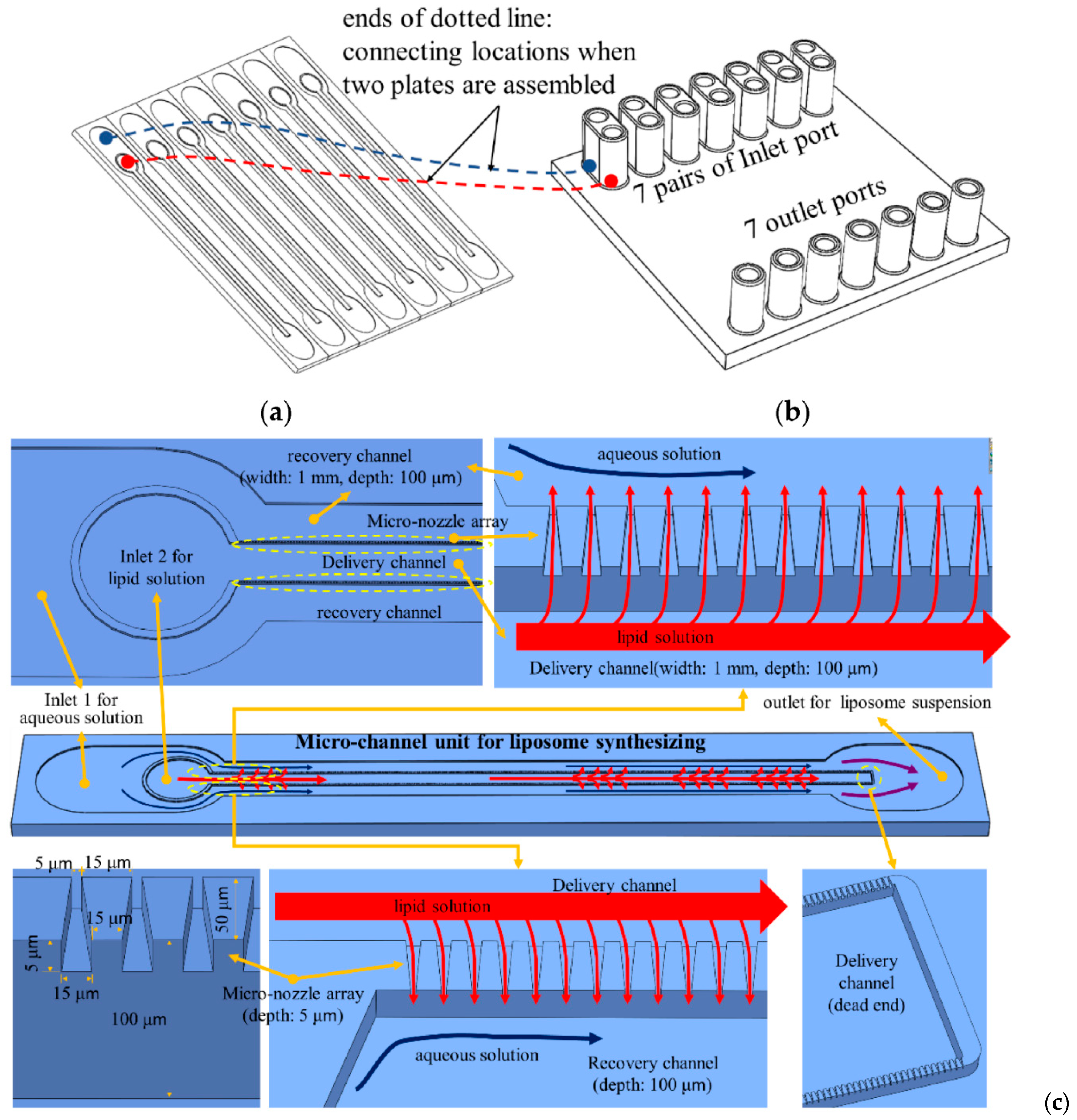
| Combined geometry device | Liposomes | Lipid solution flow rate: 3 and 4.5 mL/h Aqueous solution flow rate: 30 mL/h | Diameter range: 217–274 nm | [76] |
| Combined geometry device | PEGylated PLGA nanoparticles loaded with fluorescent dyes | Flow rate ratio—4:6 (organic: aqueous) | Average particle size—~100 nm | [78] |
| Combined geometry device | Gold nanoparticles | Helium flow rate—1.0 SCCM Gold precursor solution flow rate—0.05 mL/min | Unform particle size Single crystal structure | [84] |
| 3D printed device | Silver nanoparticles | Temperature—20 °C Reactants flow rates—30 and 120 μL/min | Average particle size—ranged from 5 ± 2 nm to 8 ± 3 nm | [103] |
| 3D printed device | Gold nanoparticles | Temperature—90 °C Reactants flow rates—40 and 100 μL/min | Average particle size—ranged from 20 ± 9 to 34 ± 12 nm | [103] |
Publisher’s Note: MDPI stays neutral with regard to jurisdictional claims in published maps and institutional affiliations. |
© 2022 by the authors. Licensee MDPI, Basel, Switzerland. This article is an open access article distributed under the terms and conditions of the Creative Commons Attribution (CC BY) license (https://creativecommons.org/licenses/by/4.0/).
Share and Cite
Niculescu, A.-G.; Mihaiescu, D.E.; Grumezescu, A.M. A Review of Microfluidic Experimental Designs for Nanoparticle Synthesis. Int. J. Mol. Sci. 2022, 23, 8293. https://doi.org/10.3390/ijms23158293
Niculescu A-G, Mihaiescu DE, Grumezescu AM. A Review of Microfluidic Experimental Designs for Nanoparticle Synthesis. International Journal of Molecular Sciences. 2022; 23(15):8293. https://doi.org/10.3390/ijms23158293
Chicago/Turabian StyleNiculescu, Adelina-Gabriela, Dan Eduard Mihaiescu, and Alexandru Mihai Grumezescu. 2022. "A Review of Microfluidic Experimental Designs for Nanoparticle Synthesis" International Journal of Molecular Sciences 23, no. 15: 8293. https://doi.org/10.3390/ijms23158293
APA StyleNiculescu, A.-G., Mihaiescu, D. E., & Grumezescu, A. M. (2022). A Review of Microfluidic Experimental Designs for Nanoparticle Synthesis. International Journal of Molecular Sciences, 23(15), 8293. https://doi.org/10.3390/ijms23158293