Nanostructured Silica with Anchoring Units: The 2D Solid Solvent for Molecules and Metal Ions

 , , , , , and
Abstract
:1. Introduction
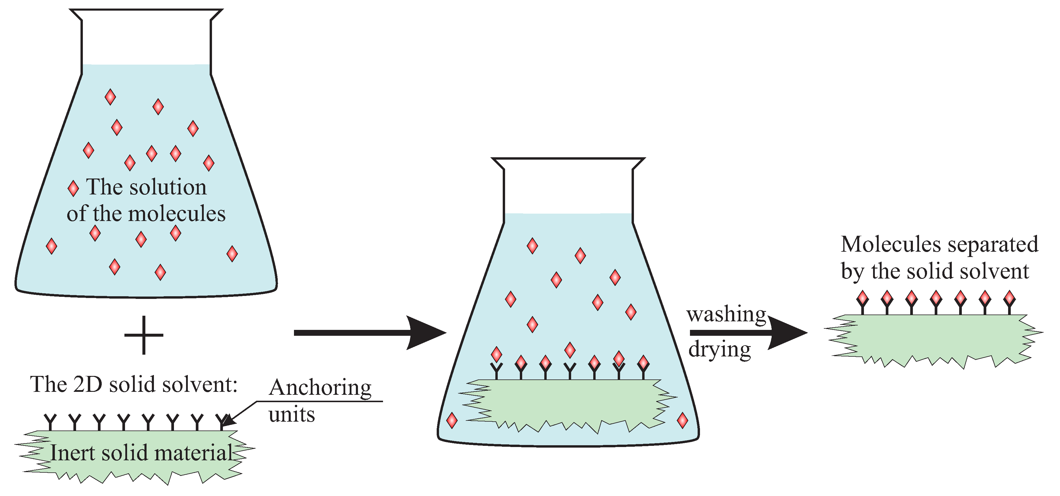
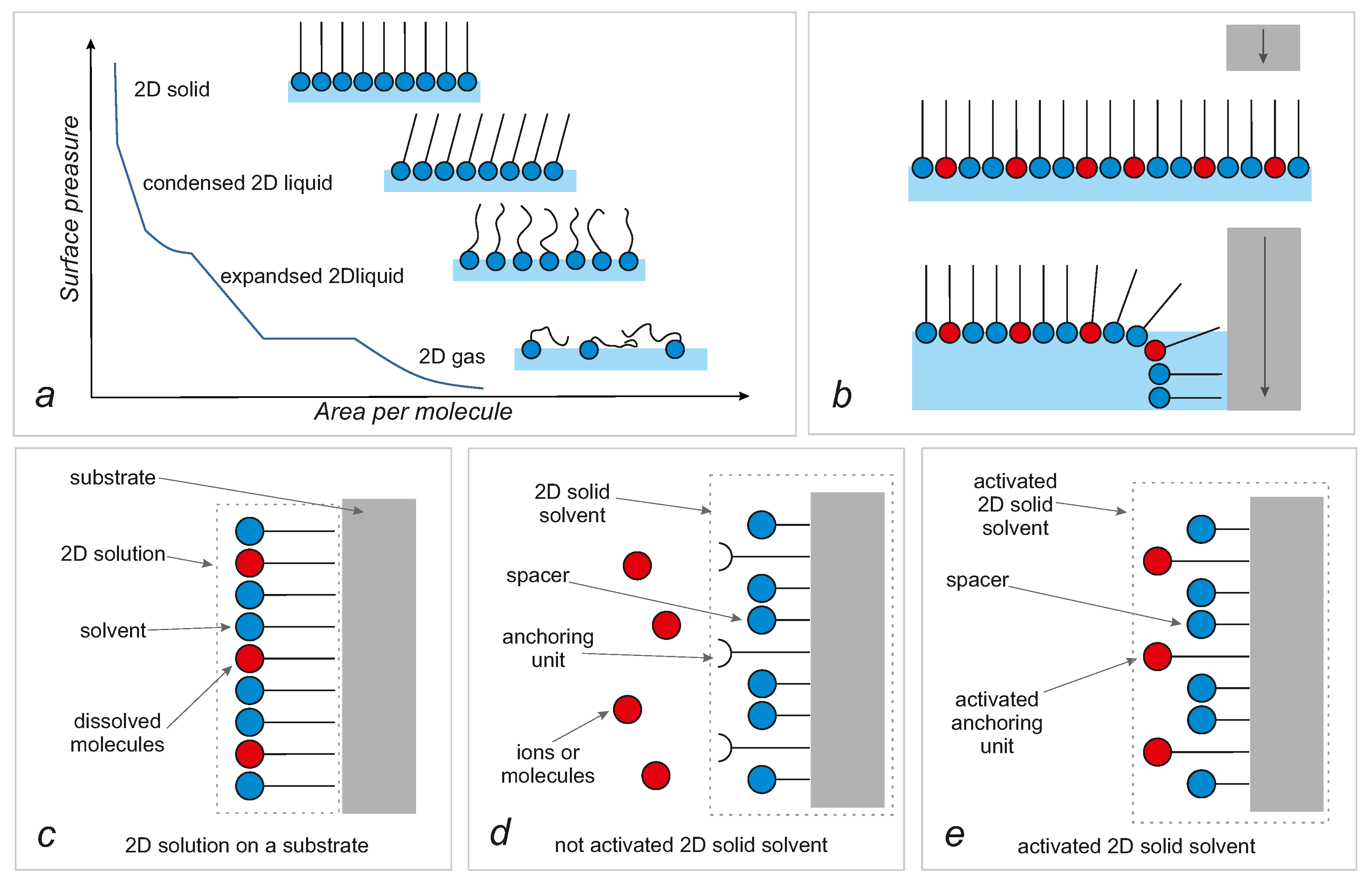
- a silica substrate, anchoring units and spacers are connected and must be treated as one part—a solid solvent;
- the functionalized surface of silica is treated as a deposited layer of a 2D solution;
- the surface is made only (is covered by) of anchoring units and spacers;
- spacers are treated as an analogue of a solvent and activated anchoring units—as an analogue of a solute;
- the reaction of activation of anchoring units is treated as an analogue of the occupation of sites in interstitial solid solutions but, for clarity, will be called activation.
2. Silica as a Support
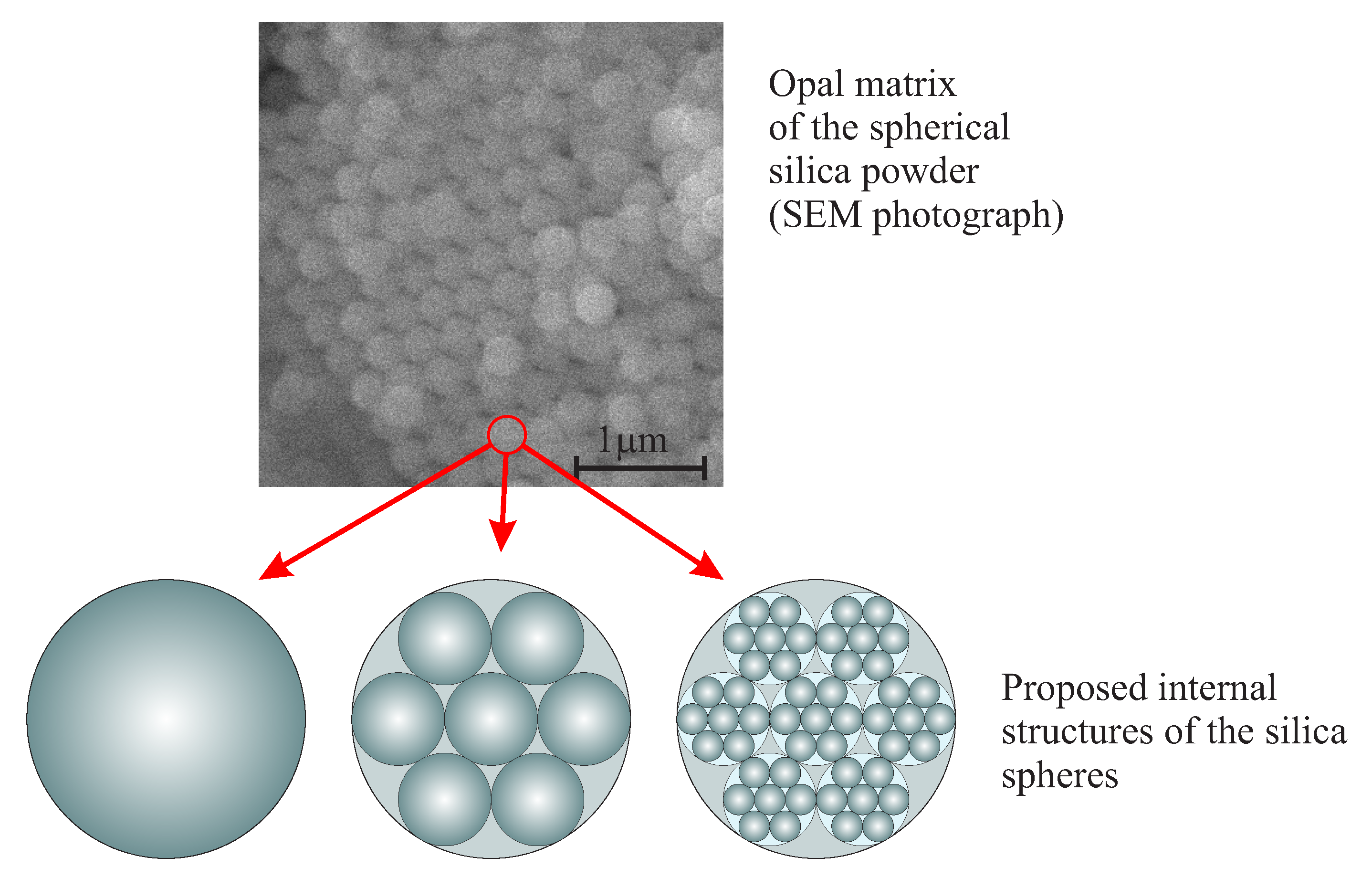
2.1. Spherical Nano-Silica
The Nanostructure and the Mechanism of the Formation of Stöber Silica Particles
- the rate of hydrolysis controls the silica growth process even for high water-to-orthosilicate ratios;
- reaction rates are faster in methanol than in ethanol;
- particles grow larger in ethanol than in methanol under the same conditions;
- ammonia increases the reaction rate and promotes the formation of larger particles;
- low water concentration favors the production of larger particles, but the excess of water has the opposite effect.
- the growth mechanism is self-sharpening—small particles grow faster than large particles;
- the growth mechanism does not alter dramatically during the reaction—the density of the silica particles and their external morphology are independent of the particle size;
- the growing particles must, at some point, achieve colloidal stability to obtain monodisperse particles.
2.2. Mesoporous Silica Structures
2.2.1. A Brief Review of Porous Silica Types and Structures
2.2.2. Formation Mechanism and Structure
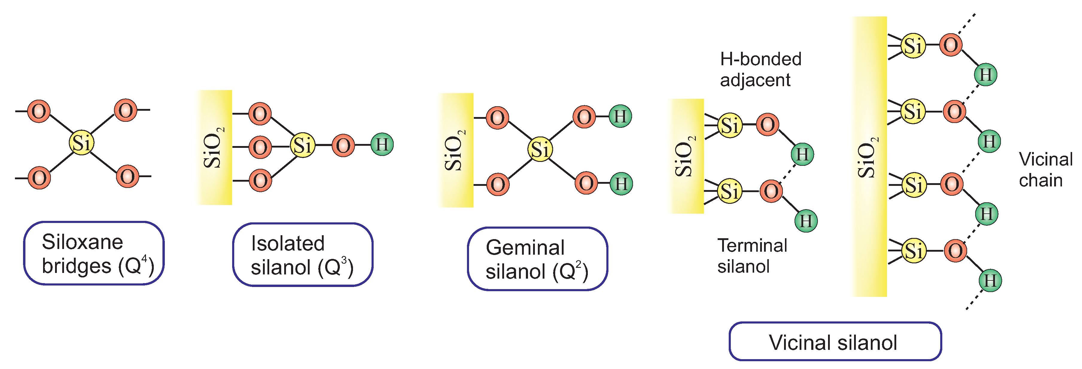
2.2.3. The Surface of Silica
3. Chemical Modification of Silica Surface
- through a reaction between pristine/modified silica surface functions and organosilanes or organic molecules (grafting);
- incorporation of functional groups via sol–gel material synthesis methodology (co-condensation).
3.1. Grafting
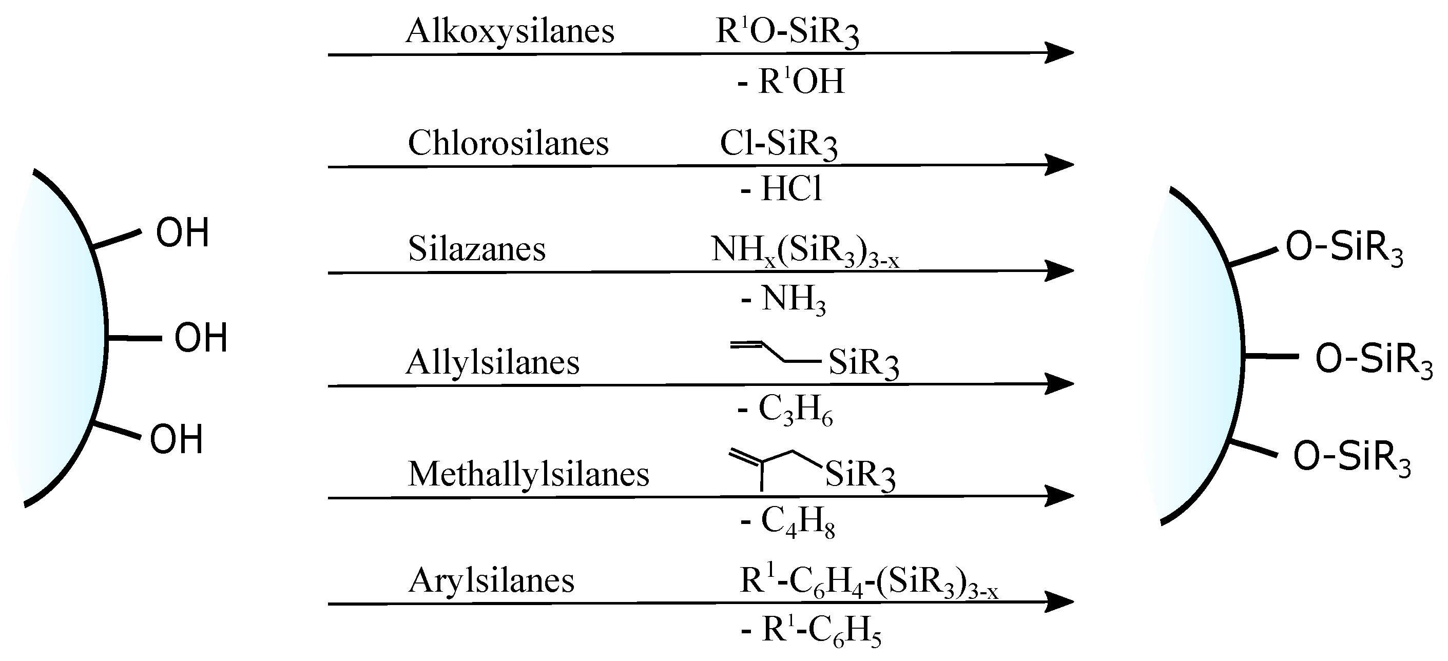
- direct grafting of silanol groups of silica—in this approach, organic or silica-organic reagents are attached to the surface via a condensation process;
- grafting of non-silanol groups—first, silanol groups of silica are modified with other chemical groups, such as Si-Hal or Si-H, and afterwards, a standard grafting is performed with desired molecules.
- a large variety of functional groups can be introduced to a material;
- for mesostructured silica, the original structure of the silica phase is usually retained—one can use pre-prepared samples with well-known structures (in the case of co-condensation, the introduction of some trialkoxysilans in the existing preparation technique could affect the formation of the assumed mesostructure);
- there is no strict requirement in the synthesis of complex silica matrix—numerous silica matrices can be purchased from commercial sources.
3.1.1. Grafting of the Silanol Groups
- susceptible to competing side reactions,
- responsive to moisture,
- tend to undergo intermolecular polymerization/polycondensation,
- can form multilayers.
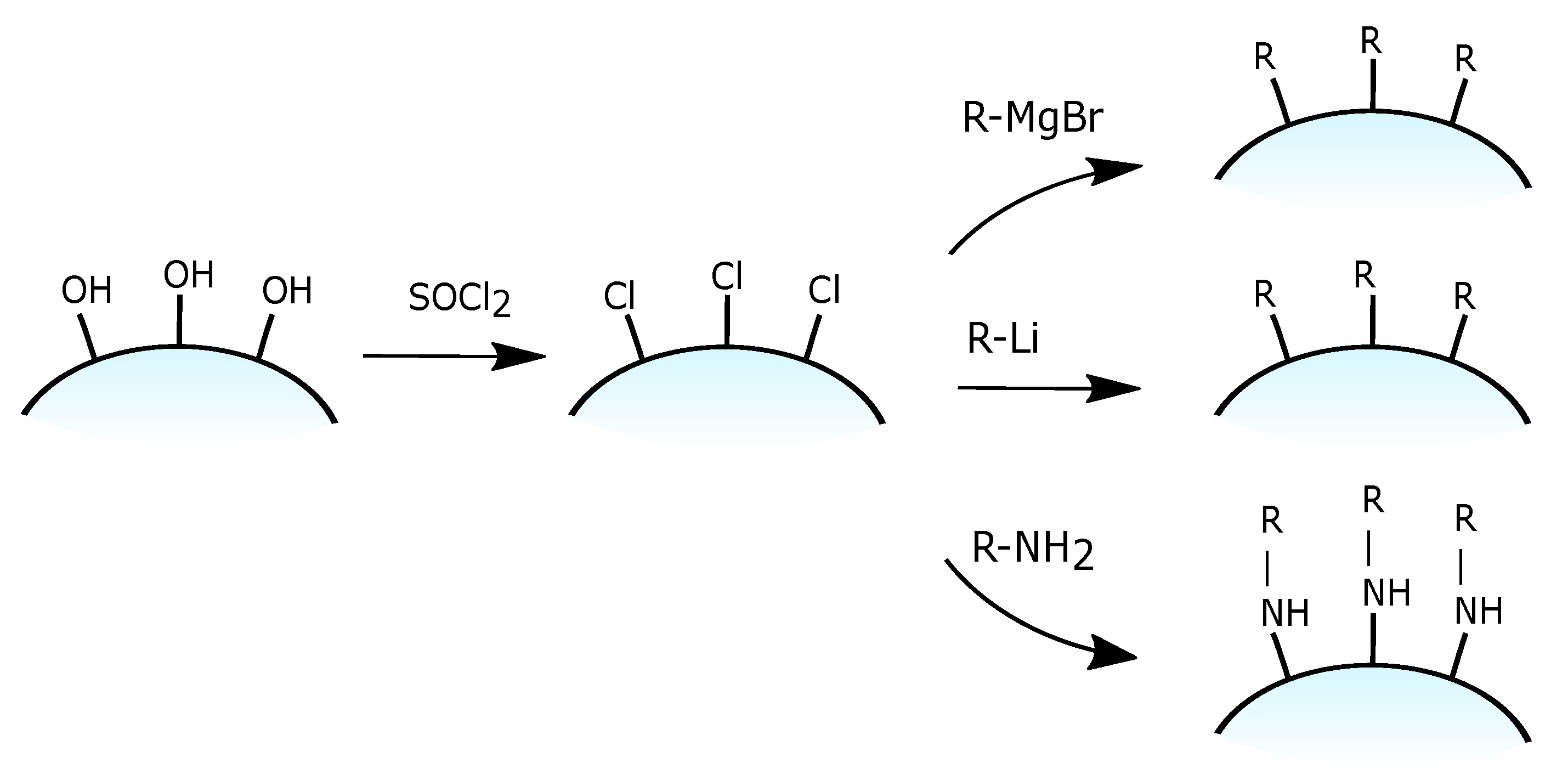
3.1.2. Grafting of Chlorinated Silica
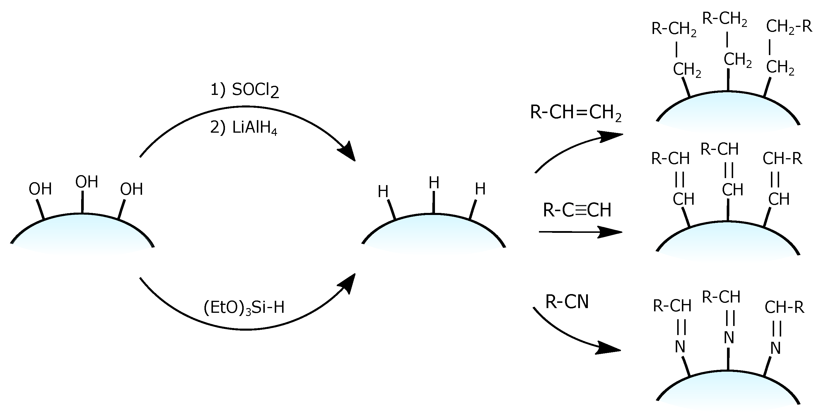
3.1.3. Grafting of a Silica Hydride
- the reduction of chlorinated silica Si-Cl groups to Si-H using lithium aluminium hydride LiAlH [100] in completely dry conditions to avoid Si–Cl bond hydrolysys;
- the single-step grafting of hydride monolayer on ordinary silica using the condensation of silane reagents (most commonly with triethoxysilane (CHO)Si-H) [101].
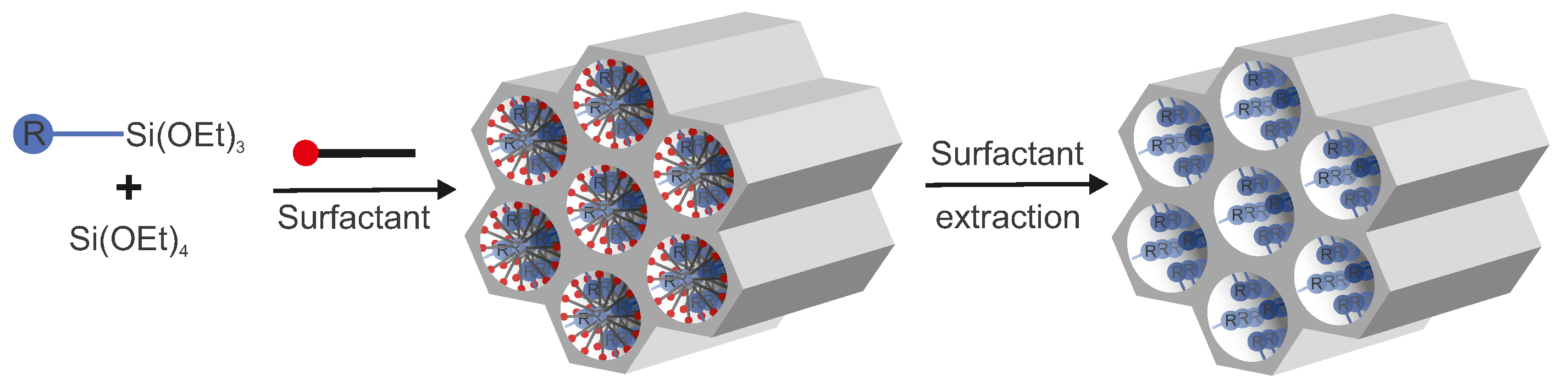
3.2. Co-Condensation
- the hydrophobicity of some organic R groups which tend to avoid interaction with polar silanol/siloxane groups;
- the hydrophobicity of organic residues; in some cases, they can interact with micelles. In this case, (RO)Si-R* molecules act not only as silica agents but also as weak structure-deriving agents. Moreover, they often slightly change pore sizes in the obtained material. Additionally, the silica source and the main surfactant can also be in the form of a single molecule [114]. For example, cetyl triethoxysilane can also condense into a lamellar solid in a concentrated acidic solution without any other silica source or a surfactant. Both MCM-41 and MCM-48 can be synthesized by using n-tetradecyldimethy(3-trimethoxysilylpropyl)ammonium chloride as the covalently bound surfactant-silica source [115];
- in a basic medium, an organosilane component undergoes lower hydrolysis and at a decreased condensation rate, in comparison to the pure inorganic precursor, which leads to retarded participation in the polycondensation process [76].
- since it is a one-pot synthesis, this method saves time due to the decreased amount of stages in the synthesis route—the synthesis and functionalization occur at the same time;
- no material loss during the process of isolation and purification of the product between its synthesis and functionalization;
- condensation occurs at the same time with the 3D structure formation. Thus, pore blocking does not occur, and pores are filled with a surfactant. In contrast to this, in post-synthesis methods, when the concentration of trialkoxysilanes is too high and the time of reaction is too long, pores can be filled with a new formed silica-based substance and be blocked;
- generally, the organic functionalities are distributed more homogeneously than in materials synthesized with the grafting process.
- The main problem with this method is related to the limitation of the maximal achievable density of the functional groups without the loss in the structure mesoscopic ordering. As it was mentioned before, not all silica agents need to have the possibility to form all four -Si-O-Si- bonds and some fraction of a silica agent can form only three (or less) bonds. However, in reality, when the amount of an agent, which cannot form all four bonds, increases, it starts to disrupt the mesoscale structure ordering. In practice, the content of organic functionalities in the modified silica phases does normally not exceed 40 molls, and typical values are even lower (5–15 molls).
- Due to the different hydrolysis and condensation rates, a part of the silica source and trialkoxysilanes can take part in homocondensation reactions and resulting in a lower number of bound organic groups.
- The increase in the concentration of a modification agent can lead to decreased pore diameter, pore volume, and specific surface area of the obtained mesoporous silica.
- Surfactants are often removed from the pores by calcination. However, this method cannot be used here since the process can destroy organic functional groups. Nevertheless, surfactants can be effectively removed by extractive methods.
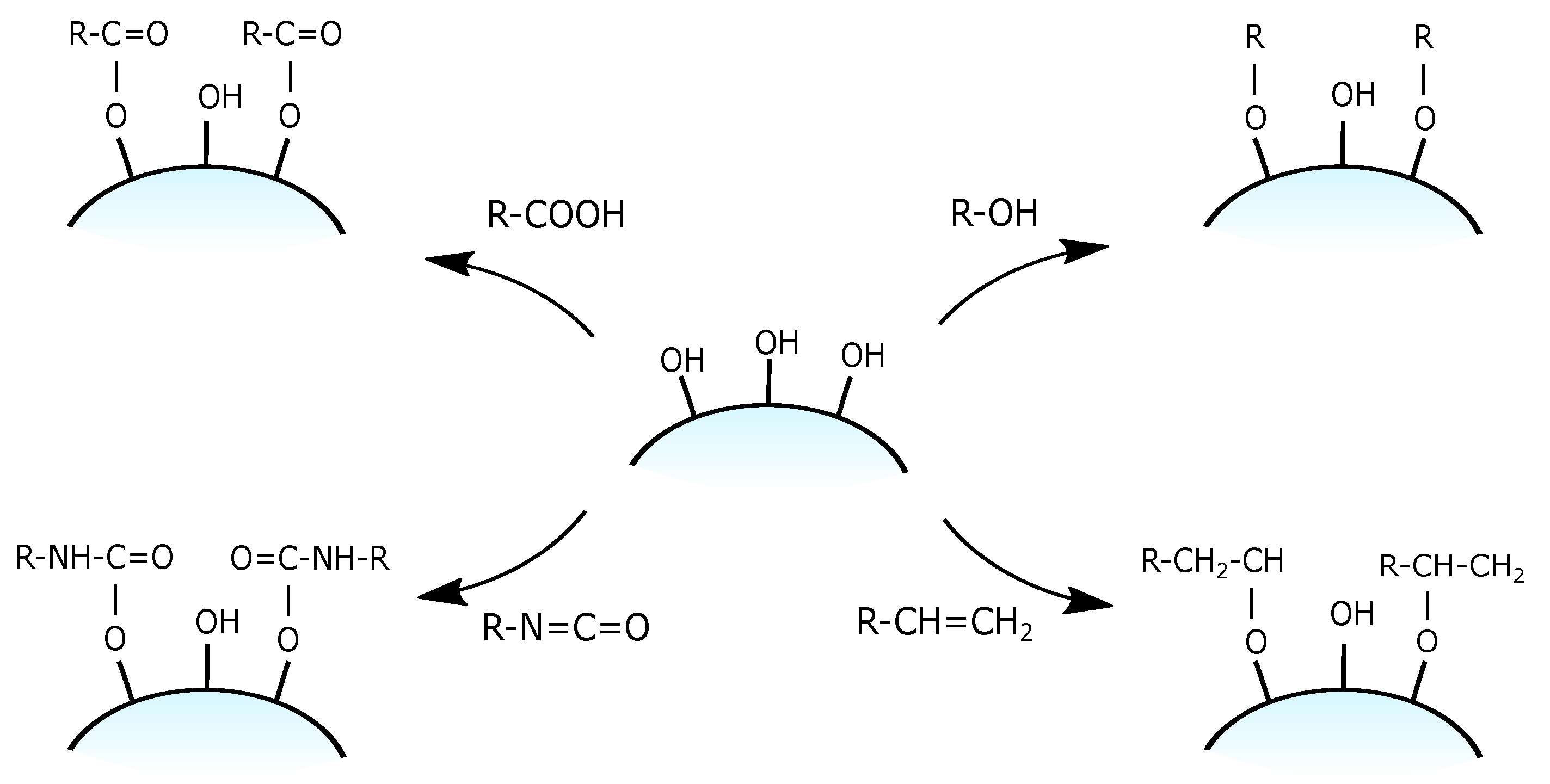
3.3. Functional Groups and Their Reactions
4. The Immobilization of Ions and Molecules by a 2D Solid Solvent: A Few Examples
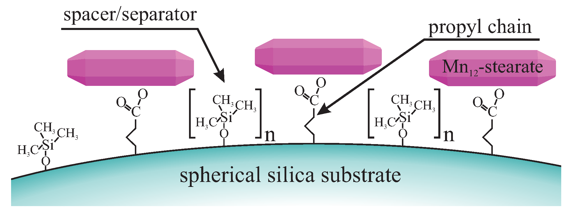
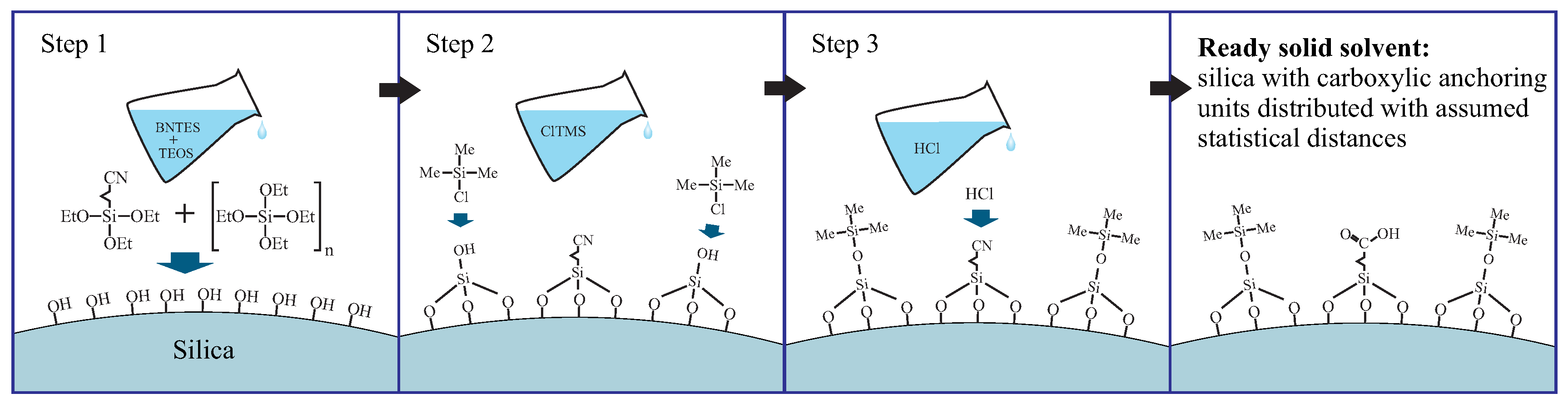
4.1. Grafting of Spherical Silica
- grafting the spherical silica by the precursors of anchoring (butyronitriletriethoxysilane—BNTES) and spacer (tetraethyl orthosilicate - TEOS) units: in this step, the statistical distances between anchoring units can be tuned by changing the proportion between TEOS and BNTES (defined by the n number in Figure 17);
- the silanation of the surface hydroxyl units with the solution of chlorotrimethyl silane (ClTMS): this step is necessary to avoid unwanted side reactions between carboxylic acid groups and surface hydroxyl units during the hydrolysis;
- acidic hydrolysis of cyano units into carboxylic acid groups.
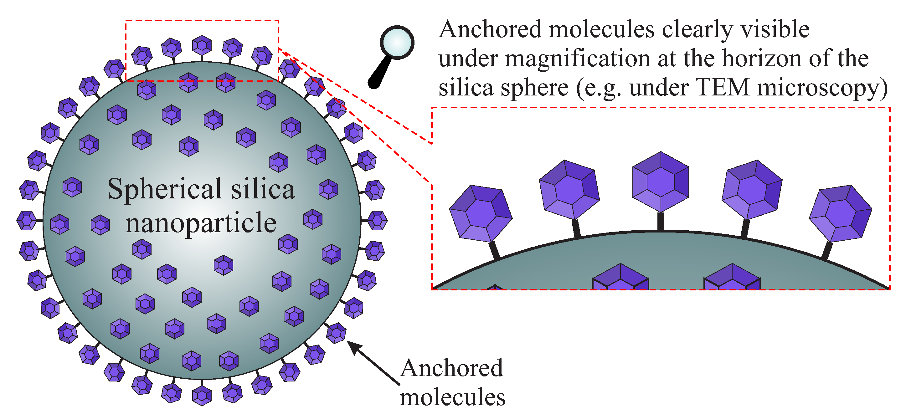
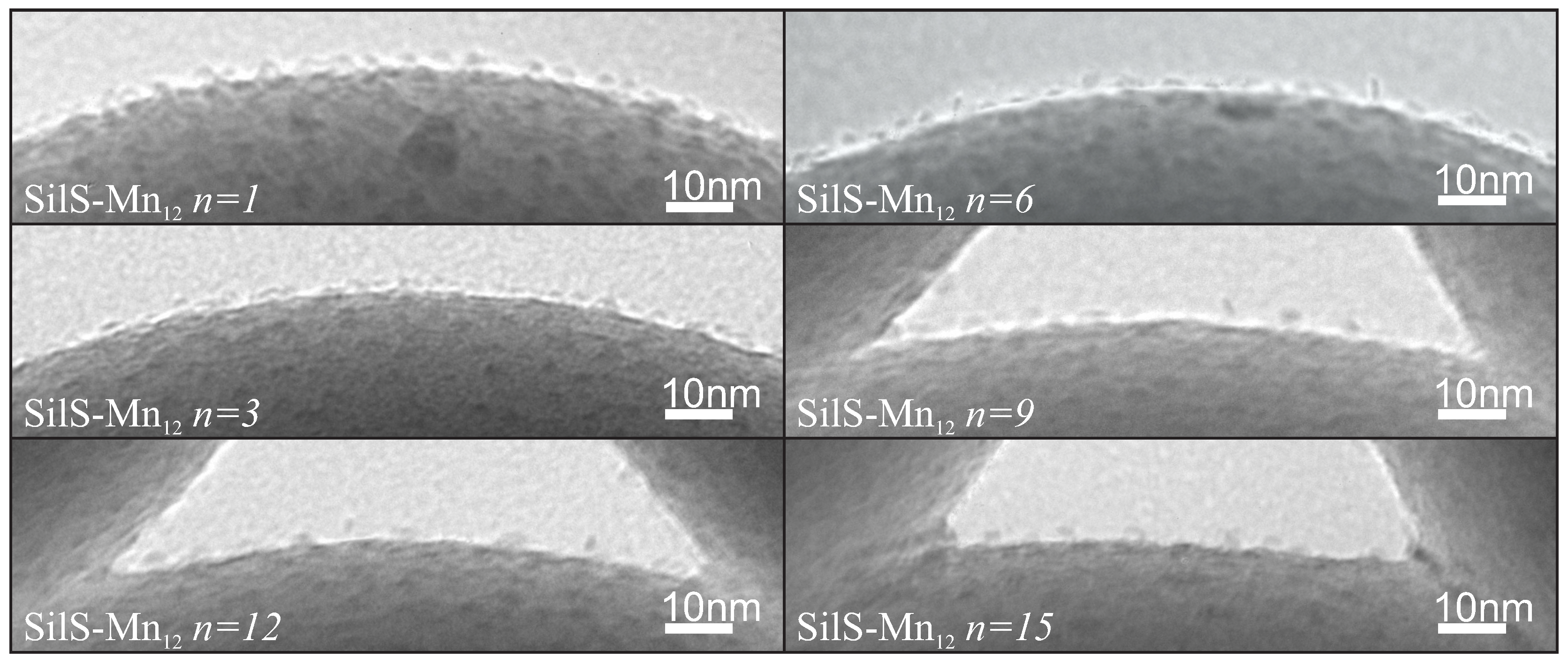
- Mn-stearate single-molecule magnets attached to the surface of silica can be directly observed with the use of TEM;
- we are able to tune the way of SMMs immobilization and their concentration at the matrix.
4.2. Mesoporous Silica for the Immobilization of Metal Ions and Molecules
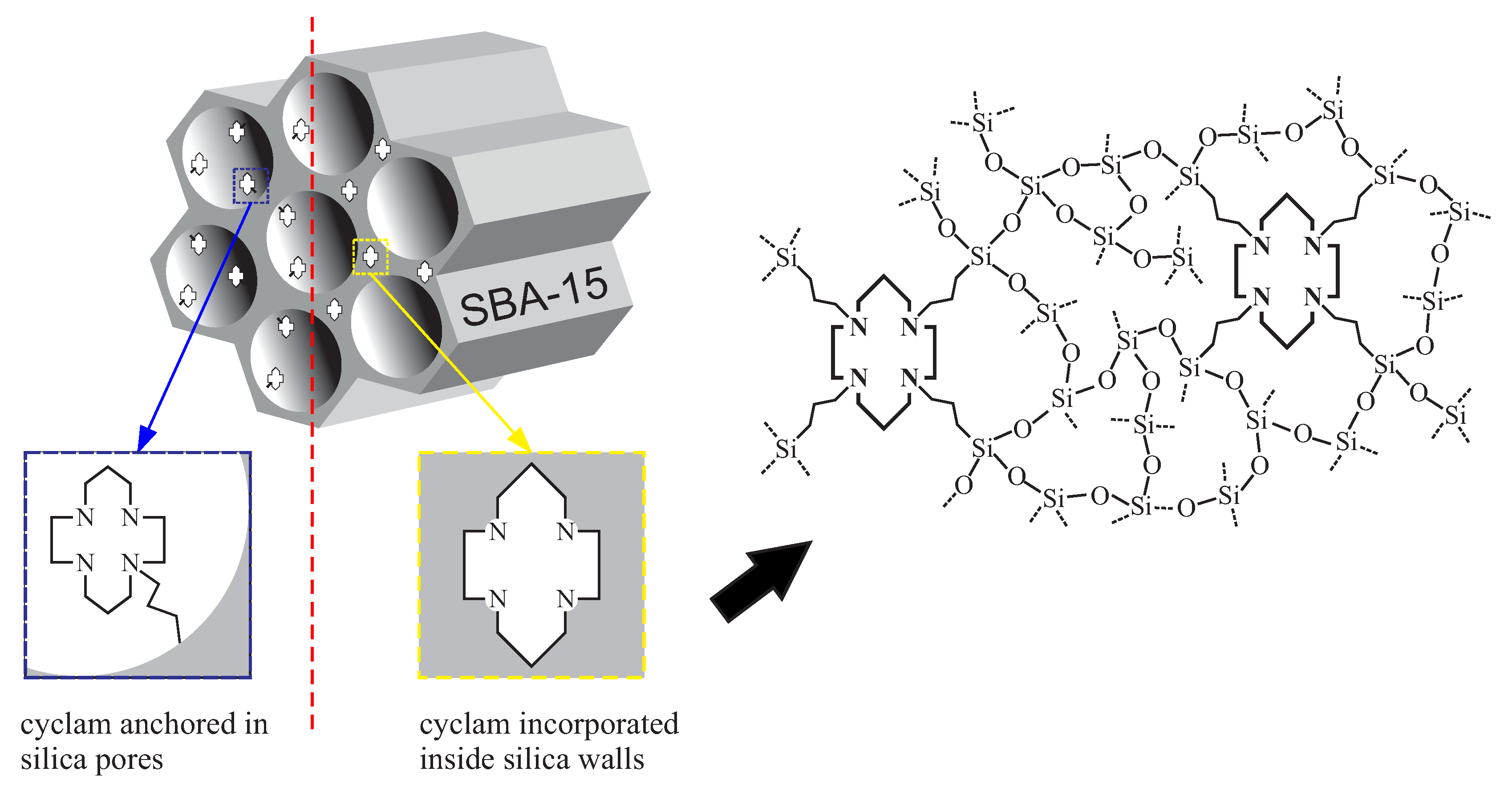
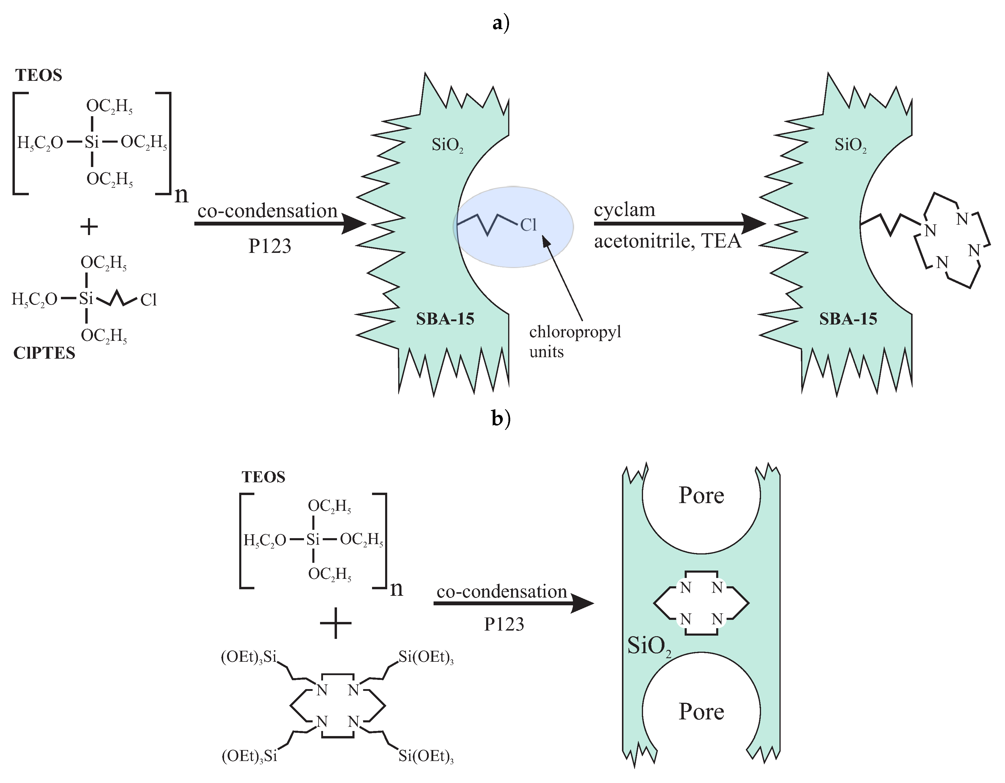
4.3. Mesoporous Silica Functionalized with Cyclam for Chelating of Chlorides
5. Conclusions
Supplementary Materials
Author Contributions
Funding
Acknowledgments
Conflicts of Interest
Abbreviations
| TEOS | tetraethyl orthosilicate |
| TMOS | tetramethyl orthosilicate |
| TPOS | tetrapentyl orthosilicate |
| TBOS | tetrabutyl orthosilicate |
| PPTES | phosphonate propyl diethyl triethoxysilane |
| BNTES | butyronitrile triethoxysilane / cyanopropyl triethoxysilane |
| P123 | (poly(ethylene glycol)-poly(propylene glycol)-poly(ethylene glycol) |
| CTAB | cetyl triethyl ammonium bromide |
References
- Feynman, R.P. There’s plenty of room at the bottom: An invitation to enter a new field of physics. In Handbook of Nanoscience, Engineering, and Technology, 3rd ed.; CRC Press: Boca Raton, FL, USA, 2012; pp. 26–35. [Google Scholar]
- Corriu, R.; Mehdi, A.; Reyé, C. Nanoporous materials: A good opportunity for nanosciences. J. Organomet. Chem. 2004, 689, 4437–4450. [Google Scholar] [CrossRef]
- Guo, Z.; Tan, L. Fundamentals and Applications of Nanomaterials; Artech House: London, UK, 2009. [Google Scholar]
- Hussain, S.A.; Dey, B.; Bhattacharjee, D.; Mehta, N. Unique supramolecular assembly through Langmuir–Blodgett (LB) technique. Heliyon 2018, 4, e01038. [Google Scholar] [CrossRef] [PubMed] [Green Version]
- Basu, J.; Sanyal, M. Ordering and growth of Langmuir–Blodgett films: X-ray scattering studies. Phys. Rep. 2002, 363, 1–84. [Google Scholar] [CrossRef]
- Mei, Q.X.; Lai, L.; Li, S.J.; Mei, P.; Wang, Y.Q.; Ma, Q.L.; Liu, Y. Surface properties and phase behavior of Gemini/conventional surfactant mixtures based on multiple quaternary ammonium salts. J. Mol. Liq. 2019, 281, 506–516. [Google Scholar] [CrossRef]
- Mixed crystal (solid solution). In IUPAC Compendium of Chemical Terminology; IUPAC: Research Triangle, NC, USA, 2019. [CrossRef]
- Holt, P.; King, D. The chemistry of silica surfaces. J. Chem. Soc. (Resumed) 1955, 773–779. [Google Scholar] [CrossRef]
- Bergna, H.E. Colloid Chemistry of Silica: An Overview; ACS Publications: Washington, DC, USA, 1994. [Google Scholar]
- Iler, R.K.; Iler, R. The chemistry of silica: Solubility, polymerization, colloid and surface properties, and biochemistry. Sci. Geol. Bull. Mem. 1979, 35, 93. [Google Scholar]
- Stöber, W.; Fink, A.; Bohn, E. Controlled growth of monodisperse silica spheres in the micron size range. J. Colloid Interface Sci. 1968, 26, 62–69. [Google Scholar] [CrossRef]
- Kim, T.G.; An, G.S.; Han, J.S.; Hur, J.U.; Park, B.G.; Choi, S.C. Synthesis of size controlled spherical silica nanoparticles via sol-gel process within hydrophilic solvent. J. Korean Ceram. Soc. 2017, 54, 49–54. [Google Scholar] [CrossRef] [Green Version]
- Ibrahim, I.A.; Zikry, A.; Sharaf, M.A. Preparation of spherical silica nanoparticles: Stober silica. J. Am. Sci. 2010, 6, 985–989. [Google Scholar]
- Wang, X.D.; Shen, Z.X.; Sang, T.; Cheng, X.B.; Li, M.F.; Chen, L.Y.; Wang, Z.S. Preparation of spherical silica particles by Stöber process with high concentration of tetra-ethyl-orthosilicate. J. Colloid Interface Sci. 2010, 341, 23–29. [Google Scholar] [CrossRef]
- Kolbe, G. Das Komplexchemische Verhalten der Kieselsäure. Ph.D. Thesis, University of Jena, Jena, Germany, 1956. [Google Scholar]
- Bogush, G.; Tracy, M.; Zukoski Iv, C. Preparation of monodisperse silica particles: Control of size and mass fraction. J. Non-Cryst. Solids 1988, 104, 95–106. [Google Scholar] [CrossRef]
- Chang, S.M.; Lee, M.; Kim, W.S. Preparation of large monodispersed spherical silica particles using seed particle growth. J. Colloid Interface Sci. 2005, 286, 536–542. [Google Scholar] [CrossRef] [PubMed]
- Enomoto, N.; Koyano, T.; Nakagawa, Z.E. Effect of ultrasound on synthesis of spherical silica. Ultrason. Sonochem. 1996, 3, S105–S109. [Google Scholar] [CrossRef]
- Matsoukas, T.; Gulari, E. Dynamics of growth of silica particles from ammonia-catalyzed hydrolysis of tetra-ethyl-orthosilicate. J. Colloid Interface Sci. 1988, 124, 252–261. [Google Scholar] [CrossRef] [Green Version]
- Matsoukas, T.; Gulari, E. Monomer-addition growth with a slow initiation step: A growth model for silica particles from alkoxides. J. Colloid Interface Sci. 1989, 132, 13–21. [Google Scholar] [CrossRef] [Green Version]
- Napper, D.H. Colloid stability. Ind. Eng. Chem. Prod. Res. Dev. 1970, 9, 467–477. [Google Scholar] [CrossRef]
- Bogush, G.; Zukoski Iv, C. Studies of the kinetics of the precipitation of uniform silica particles through the hydrolysis and condensation of silicon alkoxides. J. Colloid Interface Sci. 1991, 142, 1–18. [Google Scholar] [CrossRef]
- Bogush, G.; Zukoski Iv, C. Uniform silica particle precipitation: An aggregative growth model. J. Colloid Interface Sci. 1991, 142, 19–34. [Google Scholar] [CrossRef]
- Wells, J.; Koopal, L.; De Keizer, A. Monodisperse, nonporous, spherical silica particles. Colloids Surf. A Physicochem. Eng. Asp. 2000, 166, 171–176. [Google Scholar] [CrossRef]
- Van Blaaderen, A.; Kentgens, A. Particle morphology and chemical microstructure of colloidal silica spheres made from alkoxysilanes. J. Non-Cryst. Solids 1992, 149, 161–178. [Google Scholar] [CrossRef]
- Van Blaaderen, A.; Van Geest, J.; Vrij, A. Monodisperse colloidal silica spheres from tetraalkoxysilanes: Particle formation and growth mechanism. J. Colioid Interface Sci. 1992, 154, 481–501. [Google Scholar] [CrossRef]
- Masalov, V.; Sukhinina, N.; Kudrenko, E.; Emelchenko, G. Mechanism of formation and nanostructure of Stöber silica particles. Nanotechnology 2011, 22, 275718. [Google Scholar] [CrossRef] [PubMed]
- Karpov, I.; Samarov, E.; Masalov, V.; Bozhko, S.; Emelchenko, G. The intrinsic structure of spherical particles of opal. Phys. Solid State 2005, 47, 347–351. [Google Scholar] [CrossRef]
- Samarov, E.; Mokrushin, A.; Masalov, V.; Abrosimova, G.; Emelchenko, G. Structural modification of synthetic opals during thermal treatment. Phys. Solid State 2006, 48, 1280–1283. [Google Scholar] [CrossRef]
- Van Helden, A.; Jansen, J.; Vrij, A. Preparation and characterization of spherical monodisperse silica dispersions in nonaqueous solvents. J. Colloid Interface Sci. 1981, 81, 354–368. [Google Scholar] [CrossRef]
- Rouquerol, J.; Fairbridge, C.; Everett, D.; Haynes, J.; Pernicone, N.; Ramsay, J.; Sing, K.; Unger, K. Recommendations for the Characterization of Porous Solids. Pure Appl. Chem. 1994, 66, 1739–1758. [Google Scholar] [CrossRef]
- Cronstedt, A.F. Svenska Vetenskaps Akademiens Handlingar Stockholm. Nat. Zeolite Miner. 1756, 17, 120. [Google Scholar]
- Chiola, V.; Ritsko, J.E.; Vanderpool, C.D. Process for Producing Low Bulk Density Silica. U.S. Patent 3,556,725, 19 January 1971. [Google Scholar]
- DiRenzo, F.; Cambon, H.; Dutartre, R. A 28-year-old synthesis of micelle-templated mesoporous silica. Microporous Mater. 1997, 10, 283–286. [Google Scholar] [CrossRef]
- Yanagisawa, T.; Shimizu, T.; Kuroda, K.; Kato, C. The Preparation of Alkyltriinethylaininonium–Kaneinite Complexes and Their Conversion to Microporous Materials. Bull. Chem. Soc. Jpn. 1990, 63, 988–992. [Google Scholar] [CrossRef] [Green Version]
- Inagaki, S.; Fukushima, Y.; Kuroda, K. Synthesis of highly ordered mesoporous materials from a layered polysilicate. Chem. Commun. 1993, 680–682. [Google Scholar] [CrossRef]
- Inagaki, S. FSM-16 and mesoporous organosilicas. In Mesoporous Crystals and Related Nano-Structured Materials; Studies in Surface Science and Catalysis; Terasaki, O., Ed.; Elsevier: Stockholm, Sweden, 2004; Volume 148, pp. 109–132. [Google Scholar] [CrossRef]
- Kresge, C.; Leonowicz, M.; Roth, W.; Vartuli, J.; Beck, J. Ordered mesoporous molecular sieves synthesized by a liquid-crystal template mechanism. Nature 1992, 359, 710–712. [Google Scholar] [CrossRef]
- Beck, J.S.; Vartuli, J.C.; Roth, W.J.; Leonowicz, M.E.; Kresge, C.T.; Schmitt, K.D.; Chu, C.T.W.; Olson, D.H.; Sheppard, E.W.; McCullen, S.B.; et al. A new family of mesoporous molecular sieves prepared with liquid crystal templates. J. Am. Chem. Soc. 1992, 114, 10834–10843. [Google Scholar] [CrossRef]
- Tang, F.; Li, L.; Chen, D. Mesoporous silica nanoparticles: Synthesis, biocompatibility and drug delivery. Adv. Mater. 2012, 24, 1504–1534. [Google Scholar] [CrossRef]
- Galarneau, A.; Nader, M.; Guenneau, F.; Di Renzo, F.; Gedeon, A. Understanding the stability in water of mesoporous SBA-15 and MCM-41. J. Phys. Chem. C 2007, 111, 8268–8277. [Google Scholar] [CrossRef]
- Tanev, P.T.; Pinnavaia, T.J. Biomimetic Templating of Porous Lamellar Silicas by Vesicular Surfactant Assemblies. Science 1996, 267, 865–869. [Google Scholar] [CrossRef] [PubMed]
- Bagshaw, S.A.; Prouzet, E.; Pinnavaia, T.J. Templating of Mesoporous Molecular Sieves by Nonionic Polyethylene Oxide Surfactants. Science 1995, 269, 1242–1244. [Google Scholar] [CrossRef]
- Zhao, D.; Feng, J.; Huo, Q.; Melosh, N.; Fredrickson, G.H.; Chmelka, B.F.; Stucky, G.D. Triblock Copolymer Syntheses of Mesoporous Silica with Periodic 50 to 300 Angstrom Pores. Science 1998, 279, 548–552. [Google Scholar] [CrossRef] [Green Version]
- Wanka, G.; Hoffmann, H.; Ulbricht, W. Phase diagrams and aggregation behavior of poly (oxyethylene)-poly (oxypropylene)-poly (oxyethylene) triblock copolymers in aqueous solutions. Macromolecules 1994, 27, 4145–4159. [Google Scholar] [CrossRef]
- Celer, E.B.; Kruk, M.; Zuzek, Y.; Jaroniec, M. Hydrothermal stability of SBA-15 and related ordered mesoporous silicas with plugged pores. J. Mater. Chem. 2006, 16, 2824–2833. [Google Scholar] [CrossRef]
- Attard, G.S.; Glyde, J.C.; Goltner, C.G. Liquid-Crystalline Phases as Templates for the Synthesis of Mesoporous Silica. Nature 1995, 378, 366–368. [Google Scholar] [CrossRef]
- Chen, C.Y.; Burkett, S.L.; Li, H.X.; Davis, M.E. Studies on mesoporous materials II. Synthesis mechanism of MCM-41. Microporous Mater. 1993, 2, 27–34. [Google Scholar] [CrossRef]
- Huo, Q.; Margolese, D.I.; Ciesla, U.; Demuth, D.G.; Feng, P.; Gier, T.E.; Sieger, P.; Firouzi, A.; Chmelka, B.F. Organization of Organic Molecules with Inorganic Molecular Species into Nanocomposite Biphase Arrays. Chem. Mater. 1994, 6, 1176–1191. [Google Scholar] [CrossRef]
- Rosen, M.; Kunjappu, J. Surfactants and Interfacial Phenomena, 4th ed.; John Wiley and Sons Ltd.: New York, NY, USA, 2012; p. 616. [Google Scholar] [CrossRef]
- Vert, M.; Doi, Y.; Hellwich, K.H.; Hess, M.; Hodge, P.; Kubisa, P.; Rinaudo, M.; Schué, F. Terminology for biorelated polymers and applications (IUPAC Recommendations 2012). Pure Appl. Chem. 2012, 84, 377–410. [Google Scholar] [CrossRef]
- Hunter, R. Foundations of Colloid Science, 2nd ed.; Oxford University Press: New York, NY, USA, 1987; p. 565. [Google Scholar]
- Lawrence, M.J. Surfactant systems: Their use in drug delivery. Chem. Soc. Rev. 1994, 23, 417–424. [Google Scholar] [CrossRef]
- Klabunde, K.; Richards, R. Nanoscale Materials in Chemistry; John Wiley and Sons, Inc.: Hoboken, NJ, USA, 2009; p. 804. [Google Scholar]
- Huo, Q.; Margolese, D.; Ciesla, U.E.A. Generalized synthesis of periodic surfactant/inorganic composite materials. Nature 1994, 368, 317–321. [Google Scholar] [CrossRef]
- Firouzi, A.; Kumar, D.; Bull, L.; Besier, T.; Sieger, P.; Huo, Q.; Walker, S.; Zasadzinski, J.; Glinka, C.; Nicol, J.; et al. Cooperative organization of inorganic-surfactant and biomimetic assemblies. Science 1995, 267, 1138–1143. [Google Scholar] [CrossRef] [Green Version]
- Choi, D.G.; Yang, S.M. Effect of two-step sol-gel reaction on the mesoporous silica structure. J. Colloid Interface Sci. 2003, 261, 127–132. [Google Scholar] [CrossRef]
- Alexandridis, P.; Hatton, T.A. Poly(ethylene oxide)–poly(propylene oxide)–poly(ethylene oxide) block copolymer surfactants in aqueous solutions and at interfaces: Thermodynamics, structure, dynamics, and modeling. Colloids Surf. A Physicochem. Eng. Asp. 1995, 96, 1–46. [Google Scholar] [CrossRef]
- De Paul, S.M.; Zwanziger, J.W.; Ulrich, R.; Wiesner, U.; Spiess, H.W. Structure, Mobility, and Interface Characterization of Self-Organized Organic-Inorganic Hybrid Materials by Solid-State NMR. J. Am. Chem. Soc. 1999, 121, 5727–5736. [Google Scholar] [CrossRef]
- Kiselev, A.V.; Lygin, V.I. Infrared Spectra of Surface Compounds; Wiley: New York, NY, USA, 1975. [Google Scholar]
- Li, J.; Yang, C.; Zhang, Q.; Li, Z.; Huang, W. Effects of Fe addition on the structure and catalytic performance of mesoporous Mn/Al–SBA-15 catalysts for the reduction of NO with ammonia. Catal. Commun. 2015, 62, 24–28. [Google Scholar] [CrossRef]
- Kim, J.; Ichikuni, N.; Hara, T.; Shimazu, S. Study on the selectivity of propane photo-oxidation reaction on SBA-15 supported Mo oxide catalyst. Catal. Today 2016, 265, 90–94. [Google Scholar] [CrossRef]
- Guan, M.; Liu, W.; Shao, Y.; Huang, H.; Zhang, H. Preparation, characterization and adsorption properties studies of 3-(methacryloyloxy) propyltrimethoxysilane modified and polymerized sol–gel mesoporous SBA-15 silica molecular sieves. Microporous Mesoporous Mater. 2009, 123, 193–201. [Google Scholar] [CrossRef]
- dos Santos, S.M.L.; Nogueira, K.A.B.; de Souza Gama, M.; Lima, J.D.F.; da Silva Júnior, I.J.; de Azevedo, D.C.S. Synthesis and characterization of ordered mesoporous silica (SBA-15 and SBA-16) for adsorption of biomolecules. Microporous Mesoporous Mater. 2013, 180, 284–292. [Google Scholar] [CrossRef]
- Vansant, E.; Van Der Voort, P.; Vrancken, K. Characterization and Chemical Modification of the Silica Surface; Elsevier Science: Stockholm, Sweden, 1995; Volume 93, p. 553. [Google Scholar]
- Ek, S.; Root, A.; Peussa, M.; Niinistö, L. Determination of the hydroxyl group content in silica by thermogravimetry and a comparison with 1H MAS NMR results. Thermochim. Acta 2001, 379, 201–212. [Google Scholar] [CrossRef]
- McCool, B.; Murphy, L.; Tripp, C.P. A simple FTIR technique for estimating the surface area of silica powders and films. J. Colloid Interface Sci. 2006, 295, 294–298. [Google Scholar] [CrossRef] [PubMed]
- Zholobenko, V.L.; Plant, D.; Evans, A.J.; Holmes, S.M. Acid sites in mesoporous materials: A DRIFTS study. Microporous Mesoporous Mater. 2001, 44–45, 79–99. [Google Scholar] [CrossRef]
- Leonardelli, S.; Facchini, L.; Fretigny, C.; Tougne, P.; Legrand, A.P. Silicon-29 NMR study of silica. J. Am. Chem. Soc. 1992, 114, 6412–6418. [Google Scholar] [CrossRef]
- Liu, C.C.; Maciel, G.E. The Fumed Silica Surface: A Study by NMR. J. Am. Chem. Soc. 1996, 118, 5103–5119. [Google Scholar] [CrossRef]
- Delitala, C.; Cadoni, E.; Delpiano, D.; Meloni, D.; Alba, M.; Becerro, A.; Ferino, I. Liquid-phase thiophene adsorption on MCM-22 zeolites. Acidity, adsorption behaviour and nature of the adsorbed products. Microporous Mesoporous Mater. 2009, 118, 11–20. [Google Scholar] [CrossRef]
- Chen, J.; Li, Q.; Xu, R.; Xiao, F. Distinguishing the Silanol Groups in the Mesoporous Molecular Sieve MCM-41. Angew. Chem. Int. Ed. Engl. 1996, 34, 2694–2696. [Google Scholar] [CrossRef]
- Zhao, X.S.; Lu, G.Q.; Whittaker, A.K.; Millar, G.J.; Zhu, H.Y. Comprehensive Study of Surface Chemistry of MCM-41 Using 29Si CP/MAS NMR, FTIR, Pyridine-TPD, and TGA. J. Phys. Chem. B 1997, 101, 6525–6531. [Google Scholar] [CrossRef]
- Ide, M.; El-Roz, M.; De Canck, E.; Vicente, A.; Planckaert, T.; Bogaerts, T.; Van Driessche, I.; Lynen, F.; Van Speybroeck, V.; Thybault-Starzyk, F.; et al. Quantification of silanol sites for the most common mesoporous ordered silicas and organosilicas: Total versus accessible silanols. Phys. Chem. Chem. Phys. 2013, 15, 642–650. [Google Scholar] [CrossRef] [PubMed]
- Stein, A.; Melde, B.J.; Schroden, R.C. Hybrid Inorganic-Organic Mesoporous Silicates—Nanoscopic Reactors Coming of Age. Adv. Mater. 2000, 12, 1403–1419. [Google Scholar] [CrossRef]
- Hoffmann, F.; Fröba, M. Vitalising porous inorganic silica networks with organic functions—PMOs and related hybrid materials. Chem. Soc. Rev. 2011, 40, 608–620. [Google Scholar] [CrossRef]
- Herzer, N.; Hoeppener, S.; Schubert, U.S. Fabrication of patterned silane based self-assembled monolayers by photolithography and surface reactions on silicon-oxide substrates. Chem. Commun. 2010, 46, 5634. [Google Scholar] [CrossRef]
- Zapilko, C.; Widenmeyer, M.; Nagl, I.; Estler, F.; Anwander, R.; Raudaschl-Sieber, G.; Groeger, O.; Engelhardt, G. Advanced Surface Functionalization of Periodic Mesoporous Silica: Kinetic Control by Trisilazane Reagents. J. Am. Chem. Soc. 2006, 128, 16266–16276. [Google Scholar] [CrossRef]
- Shimada, T.; Aoki, K.; Shinoda, Y.; Nakamura, T.; Tokunaga, N.; Inagaki, S.; Hayashi, T. Functionalization on Silica Gel with Allylsilanes. A New Method of Covalent Attachment of Organic Functional Groups on Silica Gel. J. Am. Chem. Soc. 2003, 125, 4688–4689. [Google Scholar] [CrossRef]
- Yeon, Y.R.; Park, Y.; Lee, J.S.; Park, J.W.; Kang, S.G.; Jun, C.H. Sc(OTf)3-Mediated Silylation of Hydroxy Functional Groups on a Solid Surface: A Catalytic Grafting Method Operating at Room Temperature. Angew. Chem. Int. Ed. 2008, 47, 109–112. [Google Scholar] [CrossRef] [PubMed]
- Fukaya, N.; Haga, H.; Tsuchimoto, T.; ya Onozawa, S.; Sakakura, T.; Yasuda, H. Organic functionalization of the surface of silica with arylsilanes. A new method for synthesizing organic–inorganic hybrid materials. J. Organomet. Chem. 2010, 695, 2540–2542. [Google Scholar] [CrossRef]
- Park, J.W.; Park, Y.J.; Jun, C.H. Post-grafting of silica surfaces with pre-functionalized organosilanes: New synthetic equivalents of conventional trialkoxysilanes. Chem. Commun. 2011, 47, 4860. [Google Scholar] [CrossRef]
- Pujari, S.P.; Scheres, L.; Marcelis, A.T.M.; Zuilhof, H. Covalent Surface Modification of Oxide Surfaces. Angew. Chem. Int. Ed. 2014, 53, 6322–6356. [Google Scholar] [CrossRef] [PubMed]
- Kang, H.J.H.; Ali, R.F.; Paul, M.T.Y.; Radford, M.J.; Andreu, I.; Lee, A.W.H.; Gates, B.D. Tunable functionalization of silica coated iron oxide nanoparticles achieved through a silanol–alcohol condensation reaction. Chem. Commun. 2019, 55, 10452–10455. [Google Scholar] [CrossRef] [PubMed]
- Halász, I.; Sebestian, I. New Stationary Phase for Chromatography. Angew. Chem. Int. Ed. Engl. 1969, 8, 453–454. [Google Scholar] [CrossRef]
- Ter Maat, J.; Regeling, R.; Yang, M.; Mullings, M.N.; Bent, S.F.; Zuilhof, H. Photochemical covalent attachment of alkene-derived monolayers onto hydroxyl-terminated silica. Langmuir 2009, 25, 11592–11597. [Google Scholar] [CrossRef]
- Taghizadeh, M.J.; Afghihi, S.; Saidi, H. Superhydrophobic surface based silica nanoparticle modified with diisocyanate and short and long normal chain alcohols. Asian J. Nanosci. Mater. 2018, 1, 74–80. [Google Scholar]
- Stapleton, J.J.; Suchy, D.L.; Banerjee, J.; Mueller, K.T.; Pantano, C.G. Adsorption Reactions of Carboxylic Acid Functional Groups on Sodium Aluminoborosilicate Glass Fiber Surfaces. ACS Appl. Mater. Interfaces 2010, 2, 3303–3309. [Google Scholar] [CrossRef]
- Kamitori, Y.; Hojo, M.; Masuda, R.; Kimura, T.; Yoshida, T. Selective protection of carbonyl compounds. Silica gel treated with thionyl chloride as an effective catalyst for thioacetalization. J. Org. Chem. 1986, 51, 1427–1431. [Google Scholar] [CrossRef]
- Clark, J.H.; Williamson, C.J. Formation of Si—C bonds at the surface of silica and glass fibres. J. Mater. Chem. 1993, 3, 575–577. [Google Scholar] [CrossRef]
- Maity, N.; Barman, S.; Abou-Hamad, E.; D’Elia, V.; Basset, J.M. Clean chlorination of silica surfaces by a single-site substitution approach. Dalton Trans. 2018, 47, 4301–4306. [Google Scholar] [CrossRef] [Green Version]
- Locke, D.C.; Schmermund, J.T.; Banner, B. Bonded stationary phases for chromatography. Anal. Chem. 1972, 44, 90–92. [Google Scholar] [CrossRef]
- Unger, K.; Thomas, W.; Adrian, P. Herstellung oberflächenmodifizierter Adsorbentien. Kolloid-Z. Z. für Polym. 1973, 251, 45–52. [Google Scholar] [CrossRef]
- Brust, O.E.; Sebestian, I.; Halász, I. Stationäre phasen mit S-N bindung für die flügkeitschromatographie. J. Chromatogr. A 1973, 83, 15–24. [Google Scholar] [CrossRef]
- Price, P.M.; Clark, J.H.; Macquarrie, D.J. Modified silicas for clean technology. J. Chem. Soc. Dalton Trans. 2000, 101–110. [Google Scholar] [CrossRef]
- Dash, S.; Mishra, S.; Patel, S.; Mishra, B.K. Organically modified silica: Synthesis and applications due to its surface interaction with organic molecules. Adv. Colloid Interface Sci. 2008, 140, 77–94. [Google Scholar] [CrossRef]
- Borges, E.M. Silica, Hybrid Silica, Hydride Silica and Non-Silica Stationary Phases for Liquid Chromatography. J. Chromatogr. Sci. 2014, 53, 580–597. [Google Scholar] [CrossRef]
- Pesek, J.J.; Matyska, M.T. Methods for the Modification and Characterization of Oxide Surfaces. Interface Sci. 1997, 5, 103–117. [Google Scholar] [CrossRef]
- Pesek, J.J.; Matyska, M.T. Our favorite materials: Silica hydride stationary phases. J. Sep. Sci. 2009, 32, 3999–4011. [Google Scholar] [CrossRef]
- Sandoval, J.E.; Pesek, J.J. Synthesis and characterization of a hydride-modified porous silica material as an intermediate in the preparation of chemically bonded chromatographic stationary phases. Anal. Chem. 1989, 61, 2067–2075. [Google Scholar] [CrossRef]
- Chu, C.H.; Jonsson, E.; Auvinen, M.; Pesek, J.J.; Sandoval, J.E. A new approach for the preparation of a hydride-modified substrate used as an intermediate in the synthesis of surface-bonded materials. Anal. Chem. 1993, 65, 808–816. [Google Scholar] [CrossRef]
- Pesek, J.J.; Matyska, M.T.; Oliva, M.; Evanchic, M. Synthesis and characterization of bonded phases made via hydrosilation of alkynes on silica hydride surfaces. J. Chromatogr. A 1998, 818, 145–154. [Google Scholar] [CrossRef]
- Pesek, J.J.; Matyska, M.T.; Muley, S. Synthesis and characterization of a new type of chemically bonded liquid crystal stationary phase for HPLC. Chromatographia 2000, 52, 439–444. [Google Scholar] [CrossRef]
- Kang, K.K.; Rhee, H.K. Synthesis and characterization of novel mesoporous silica with large wormhole-like pores: Use of TBOS as silicon source. Microporous Mesoporous Mater. 2005, 84, 34–40. [Google Scholar] [CrossRef]
- Rahmat, N.; Hamzah, F.; Sahiron, N.; Mazlan, M.; Zahari, M.M. Sodium silicate as source of silica for synthesis of mesoporous SBA-15. IOP Conf. Ser. Mater. Sci. Eng. 2016, 133, 012011. [Google Scholar] [CrossRef] [Green Version]
- Wei, F.Y.; Liu, Z.W.; Lu, J.; Liu, Z.T. Synthesis of mesoporous MCM-48 using fumed silica and mixed surfactants. Microporous Mesoporous Mater. 2010, 131, 224–229. [Google Scholar] [CrossRef]
- Chen, L.; Xu, J.; Zhang, W.H.; Holmes, J.D.; Morris, M.A. Syntheses of complex mesoporous silicas using mixtures of nonionic block copolymer surfactants: Understanding formation of different structures using solubility parameters. J. Colloid Interface Sci. 2011, 353, 169–180. [Google Scholar] [CrossRef]
- Blin, J.L.; Otjacques, C.; Herrier, G.; Su, B.L. Pore Size Engineering of Mesoporous Silicas Using Decane as Expander. Langmuir 2000, 16, 4229–4236. [Google Scholar] [CrossRef]
- Asefa, T.; MacLachlan, M.J.; Coombs, N.; Ozin, G.A. Periodic mesoporous organosilicas with organic groups inside the channel walls. Nature 1999, 402, 867–871. [Google Scholar] [CrossRef]
- Inagaki, S.; Guan, S.; Fukushima, Y.; Ohsuna, T.; Terasaki, O. Novel Mesoporous Materials with a Uniform Distribution of Organic Groups and Inorganic Oxide in Their Frameworks. J. Am. Chem. Soc. 1999, 121, 9611–9614. [Google Scholar] [CrossRef]
- Melde, B.J.; Holland, B.T.; Blanford, C.F.; Stein, A. Mesoporous Sieves with Unified Hybrid Inorganic/Organic Frameworks. Chem. Mater. 1999, 11, 3302–3308. [Google Scholar] [CrossRef]
- Park, S.S.; Moorthy, M.S.; Ha, C.S. Periodic mesoporous organosilicas for advanced applications. NPG Asia Mater. 2014, 6, e96. [Google Scholar] [CrossRef]
- Goto, Y.; Mizoshita, N.; Waki, M.; Ikai, M.; Maegawa, Y.; Inagaki, S. Synthesis and Applications of Periodic Mesoporous Organosilicas. In Chemistry of Silica and Zeolite-Based Materials; Elsevier: Stockholm, Sweden, 2019; pp. 1–25. [Google Scholar] [CrossRef]
- Lintang, H.O.; Yuliati, L. Designed Mesoporous Materials toward Multifunctional Organic Silica Nanocomposites. In Mesoporous Materials—Properties and Applications; IntechOpen: London, UK, 2019. [Google Scholar] [CrossRef] [Green Version]
- Huo, Q.; Margolese, D.I.; Stucky, G.D. Surfactant Control of Phases in the Synthesis of Mesoporous Silica-Based Materials. Chem. Mater. 1996, 8, 1147–1160. [Google Scholar] [CrossRef]
- Sullivan, T.P.; Huck, W.T.S. Reactions on Monolayers: Organic Synthesis in Two Dimensions. Eur. J. Org. Chem. 2003, 2003, 17–29. [Google Scholar] [CrossRef]
- Haensch, C.; Hoeppener, S.; Schubert, U.S. Chemical modification of self-assembled silane based monolayers by surface reactions. Chem. Soc. Rev. 2010, 39, 2323. [Google Scholar] [CrossRef] [PubMed]
- Lummerstorfer, T.; Hoffmann, H. Click Chemistry on Surfaces: 1, 3-Dipolar Cycloaddition Reactions of Azide-Terminated Monolayers on Silica. J. Phys. Chem. B 2004, 108, 3963–3966. [Google Scholar] [CrossRef]
- Khung, Y.L.; Narducci, D. Surface modification strategies on mesoporous silica nanoparticles for anti-biofouling zwitterionic film grafting. Adv. Colloid Interface Sci. 2015, 226, 166–186. [Google Scholar] [CrossRef]
- Ziarani, G.M.; Hassanzadeh, Z.; Gholamzadeh, P.; Asadi, S.; Badiei, A. Advances in click chemistry for silica-based material construction. RSC Adv. 2016, 6, 21979–22006. [Google Scholar] [CrossRef]
- van den Berg, S.A.; Tu, J.; Sliedregt, K.M.; Kros, A.; Wennekes, T.; Zuilhof, H. Clickable Mesoporous Silica via Functionalization with 1, omega-Alkenes. Adv. Mater. Interfaces 2014, 1, 1300061. [Google Scholar] [CrossRef]
- Lowe, A.B. Thiol–ene “click” reactions and recent applications in polymer and materials synthesis: A first update. Polym. Chem. 2014, 5, 4820–4870. [Google Scholar] [CrossRef]
- Wasserman, S.R.; Tao, Y.T.; Whitesides, G.M. Structure and reactivity of alkylsiloxane monolayers formed by reaction of alkyltrichlorosilanes on silicon substrates. Langmuir 1989, 5, 1074–1087. [Google Scholar] [CrossRef]
- Ziarani, G.M.; Lashgari, N.; Badiei, A. Sulfonic acid-functionalized mesoporous silica (SBA-Pr-SO3H) as solid acid catalyst in organic reactions. J. Mol. Catal. A Chem. 2015, 397, 166–191. [Google Scholar] [CrossRef]
- Chaudhary, V.; Sharma, S. An overview of ordered mesoporous material SBA-15: Synthesis, functionalization and application in oxidation reactions. J. Porous Mater. 2017, 24, 741–749. [Google Scholar] [CrossRef]
- Laskowski, L.; Laskowska, M. Functionalization of SBA-15 mesoporous silica by Cu-phosphonate units: Probing of synthesis route. J. Solid State Chem. 2014, 220, 221–226. [Google Scholar] [CrossRef]
- Laskowski, Ł.; Laskowska, M.; Jelonkiewicz, J.; Galkowski, T.; Pawlik, P.; Piech, H.; Doskocz, M. Iron doped SBA-15 mesoporous silica studied by Mössbauer spectroscopy. J. Nanomater. 2016, 2016. [Google Scholar] [CrossRef] [Green Version]
- Laskowska, M.; Laskowski, L.; Jelonkiewicz, J. SBA-15 mesoporous silica activated by metal ions–Verification of molecular structure on the basis of Raman spectroscopy supported by numerical simulations. J. Mol. Struct. 2015, 1100, 21–26. [Google Scholar] [CrossRef]
- Bałanda, M.; Pełka, R.; Fitta, M.; Laskowski, Ł.; Laskowska, M. Relaxation and magnetocaloric effect in the Mn 12 molecular nanomagnet incorporated into mesoporous silica: A comparative study. RSC Adv. 2016, 6, 49179–49186. [Google Scholar]
- Laskowski, L.; Kityk, I.; Konieczny, P.; Pastukh, O.; Schabikowski, M.; Laskowska, M. The Separation of the Mn12 Single-Molecule Magnets onto Spherical Silica Nanoparticles. Nanomaterials 2019, 9, 764. [Google Scholar] [CrossRef] [PubMed] [Green Version]
- Mannini, M.; Pineider, F.; Sainctavit, P.; Danieli, C.; Otero, E.; Sciancalepore, C.; Talarico, A.M.; Arrio, M.A.; Cornia, A.; Gatteschi, D.; et al. Magnetic memory of a single-molecule quantum magnet wired to a gold surface. Nat. Mater. 2009, 8, 194–197. [Google Scholar] [CrossRef]
- Park, C.D.; Jeong, D.Y. Soluble Single-Molecule Magnet: Mn12-stearate. Bull. Korean Chem. Soc. 2001, 22, 611–615. [Google Scholar]
- Laskowska, M.; Pastukh, O.; Konieczny, P.; Dulski, M.; Zalsiński, M.; Laskowski, L. Magnetic Behaviour of Mn12-Stearate Single-Molecule Magnets Immobilized on the Surface of 300 nm Spherical Silica Nanoparticles. Materials 2020, 13, 2624. [Google Scholar] [CrossRef]
- Laskowska, M.; Oyama, M.; Kityk, I.; Marszalek, M.; Dulski, M.; Laskowski, L. Surface functionalization by silver-containing molecules with controlled distribution of functionalities. Appl. Surf. Sci. 2019, 481, 433–436. [Google Scholar] [CrossRef]
- Laskowska, M.; Pastukh, O.; Kuźma, D.; Laskowski, Ł. How to Control the Distribution of Anchored, Mn12–Stearate, Single-Molecule Magnets. Nanomaterials 2019, 9, 1730. [Google Scholar] [CrossRef] [PubMed] [Green Version]
- Pastukh, O.; Konieczny, P.; Czernia, D.; Laskowska, M.; Dulski, M.; Laskowski, Ł. Aging effect on the magnetic properties of Mn12-stearate single-molecule magnets anchored onto the surface of spherical silica nanoparticles. Mater. Sci. Eng. B 2020, 261, 114670. [Google Scholar] [CrossRef]
- Laskowski, Ł.; Laskowska, M.; Dulski, M.; Zubko, M.; Jelonkiewicz, J.; Perzanowski, M.; Vila, N.; Walcarius, A. Multi-step functionalization procedure for fabrication of vertically aligned mesoporous silica thin films with metal-containing molecules localized at the pores bottom. Microporous Mesoporous Mater. 2019, 274, 356–362. [Google Scholar] [CrossRef]
- Laskowski, Ł.; Laskowska, M.; Jelonkiewicz, J.; Boullanger, A. Molecular Approach to Hopfield Neural Network. In Proceedings of the International Conference on Artificial Intelligence and Soft Computing, Zakopane, Poland, 14–18 June 2005; Springer: London, UK, 2015; pp. 72–78. [Google Scholar]
- Laskowski, Ł.; Laskowska, M.; Jelonkiewicz, J.; Piech, H.; Galkowski, T.; Boullanger, A. The concept of molecular neurons. In Proceedings of the International Conference on Artificial Intelligence and Soft Computing, Zakopane, Poland, 12–16 June 2016; Springer: London, UK, 2016; pp. 494–501. [Google Scholar]
- Laskowska, M.; Laskowski, Ł.; Jelonkiewicz, J.; Piech, H.; Galkowski, T.; Boullanger, A. Porous Silica Templated Nanomaterials for Artificial Intelligence and IT Technologies. In Proceedings of the International Conference on Artificial Intelligence and Soft Computing, Zakopane, Poland, 11–15 June 2017; Springer: London, UK, 2017; pp. 509–517. [Google Scholar]
- Dermont, G.; Bergeron, M.; Mercier, G.; Richer-Laflèche, M. Soil washing for metal removal: A review of physical/chemical technologies and field applications. J. Hazard. Mater. 2008, 152, 1–31. [Google Scholar] [CrossRef]
- Laskowski, Ł.; Laskowska, M.; Bałanda, M.; Fitta, M.; Kwiatkowska, J.; Dziliński, K.; Karczmarska, A. Mesoporous silica SBA-15 functionalized by nickel–phosphonic units: Raman and magnetic analysis. Microporous Mesoporous Mater. 2014, 200, 253–259. [Google Scholar] [CrossRef]
- Laskowska, M.; Kityk, I.; Dulski, M.; Jędryka, J.; Wojciechowski, A.; Jelonkiewicz, J.; Wojtyniak, M.; Laskowski, Ł. Functionalized mesoporous silica thin films as a tunable nonlinear optical material. Nanoscale 2017, 9, 12110–12123. [Google Scholar] [CrossRef] [PubMed] [Green Version]
- Laskowski, L.; Laskowska, M.; Fijalkowski, K.; Piech, H.; Jelonkiewicz, J.; Jaskulak, M.; Gnatowski, A.; Dulski, M. New class of antimicrobial agents: SBA-15 silica containing anchored copper ions. J. Nanomater. 2017, 2017. [Google Scholar] [CrossRef]
- Laskowska, M.; Kityk, I.; Pastukh, O.; Dulski, M.; Zubko, M.; Jedryka, J.; Cpałka, K.; Zieliński, P.M.; Laskowski, Ł. Nanocomposite for photonics—Nickel pyrophosphate nanocrystals synthesised in silica nanoreactors. Microporous Mesoporous Mater. 2020, 306, 110435. [Google Scholar] [CrossRef]
- Laskowski, Ł.; Majtyka-Piłat, A.; Cpałka, K.; Zubko, M.; Laskowska, M. Synthesis in Silica Nanoreactor: Copper Pyrophosphate Quantum Dots and Silver Oxide Nanocrystallites Inside Silica Mezochannels. Materials 2020, 13, 2009. [Google Scholar] [CrossRef]
- Laskowska, M.; Bałanda, M.; Fitta, M.; Dulski, M.; Zubko, M.; Pawlik, P.; Laskowski, Ł. Magnetic behaviour of Mn12-stearate single-molecule magnets immobilized inside SBA-15 mesoporous silica matrix. J. Magn. Magn. Mater. 2019, 478, 20–27. [Google Scholar] [CrossRef]
- Dulski, M.; Laskowska, M.; Sułowicz, S.; Krzykawski, T.; Pastukh, O.; Zieliński, P.; Pawlik, P.; Nowak, A. The impact of the functionalization of silica mesopores on the structural and biological features of SBA-15. Microporous Mesoporous Mater. 2020, 306, 110453. [Google Scholar] [CrossRef]
- Laskowski, L.; Kassiba, A.; Makowska-Janusik, M.; Mehdi, A.; Gibaud, A.; Errien, N.; Swiatek, J. Magnetic behaviour of nickel-cyclam complexes in mesoporous silica: EPR investigations. J. Phys. Condens. Matter 2009, 21, 076004. [Google Scholar] [CrossRef] [PubMed]
- Laskowska, M.; Dulski, M.; Marszałek, M.; Zubko, M.; Laskowski, Ł. Vertically aligned porous silica thin films functionalized by nickel chloride incorporated in walls. Microporous Mesoporous Mater. 2019, 276, 201–206. [Google Scholar] [CrossRef]


| Mesophase (Structure) | Surfactant | Interaction Pathway | Interaction Scheme |
|---|---|---|---|
| MCM-41 (2D hexadonal P6mm), MCM-48 (3D cubic Ia3d), FSM-16 (2D hexagonal P6mm) | CTAB (cetyltrimethylammonium bromide) | (electrostatic force) | 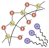 |
| SBA-1 (Cubic Pm3n), SBA-2 (3D hexagonal P6/mmc) | GS (gemini surfactant) | (electrostatic force) | 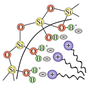 |
| SBA-3 (2D hexagonal P6mm) | CTAB | ||
| HMS (hexagonal-like) | DDA (dodecylamine) | (hydrogen bond) | 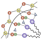 |
| MSU (hexagonal-like) | PEO (poly(ethylene oxide)-based) | (hydrogen bond) | |
| SBA-15 (2D hexagonal P6mm) | Pluronic P123 | (weak electrostatic force) |  |
| Class | Formula | Substituent |
|---|---|---|
| Passive functional groups | ||
| Alkanes | (RO)Si-CH | methyl |
| (RO)Si-CH | ethyl- | |
| (RO)Si-CH | propyl- | |
| (RO)Si-CH-CH-(CH) | isobutyl- | |
| (RO)Si-CH | octyl- | |
| (RO)Si-CH | dodecyl- | |
| Fluorinated alkanes |  | 3,3,3-trifluoropropyl- |
 | 1H,1H,2H,2H-perfluorooctyl- | |
| Cycloalkanes | 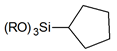 | cyclopentyl- |
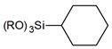 | cyclohextyl- | |
| Aromatic rings | 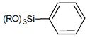 | phenyl- |
 | 2-phenylethyl- | |
| Reactive functional groups | ||
| Alkenes |  | vinyl- |
 | allyl- | |
 | 7-octen-1-yl- | |
| Halogen-based | 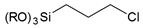 | 3-chloropropyl- |
 | 3-bromopropyl- | |
 | 3-iodopropyl- | |
| Simple terminal heterogroups |  | 3-mercaptopropyl- |
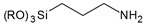 | 3-aminopropyl- | |
 | 3-(Triethoxysilyl)propionitrile | |
 | 1 | |
| Complex terminal organics |  | N-ethylenediamino- |
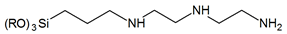 | N-diethylenetriamino- | |
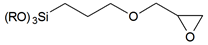 | 3-glycidyloxypropyl- | |
 | 3-propyl acrylate | |


Publisher’s Note: MDPI stays neutral with regard to jurisdictional claims in published maps and institutional affiliations. |
© 2020 by the authors. Licensee MDPI, Basel, Switzerland. This article is an open access article distributed under the terms and conditions of the Creative Commons Attribution (CC BY) license (http://creativecommons.org/licenses/by/4.0/).
Share and Cite
Laskowska, M.; Pastukh, O.; Fedorchuk, A.; Schabikowski, M.; Kowalczyk, P.; Zalasiński, M.; Laskowski, Ł. Nanostructured Silica with Anchoring Units: The 2D Solid Solvent for Molecules and Metal Ions. Int. J. Mol. Sci. 2020, 21, 8137. https://doi.org/10.3390/ijms21218137
Laskowska M, Pastukh O, Fedorchuk A, Schabikowski M, Kowalczyk P, Zalasiński M, Laskowski Ł. Nanostructured Silica with Anchoring Units: The 2D Solid Solvent for Molecules and Metal Ions. International Journal of Molecular Sciences. 2020; 21(21):8137. https://doi.org/10.3390/ijms21218137
Chicago/Turabian StyleLaskowska, Magdalena, Oleksandr Pastukh, Andrii Fedorchuk, Mateusz Schabikowski, Paweł Kowalczyk, Marcin Zalasiński, and Łukasz Laskowski. 2020. "Nanostructured Silica with Anchoring Units: The 2D Solid Solvent for Molecules and Metal Ions" International Journal of Molecular Sciences 21, no. 21: 8137. https://doi.org/10.3390/ijms21218137
APA StyleLaskowska, M., Pastukh, O., Fedorchuk, A., Schabikowski, M., Kowalczyk, P., Zalasiński, M., & Laskowski, Ł. (2020). Nanostructured Silica with Anchoring Units: The 2D Solid Solvent for Molecules and Metal Ions. International Journal of Molecular Sciences, 21(21), 8137. https://doi.org/10.3390/ijms21218137