Sample Delivery Media for Serial Crystallography


Abstract
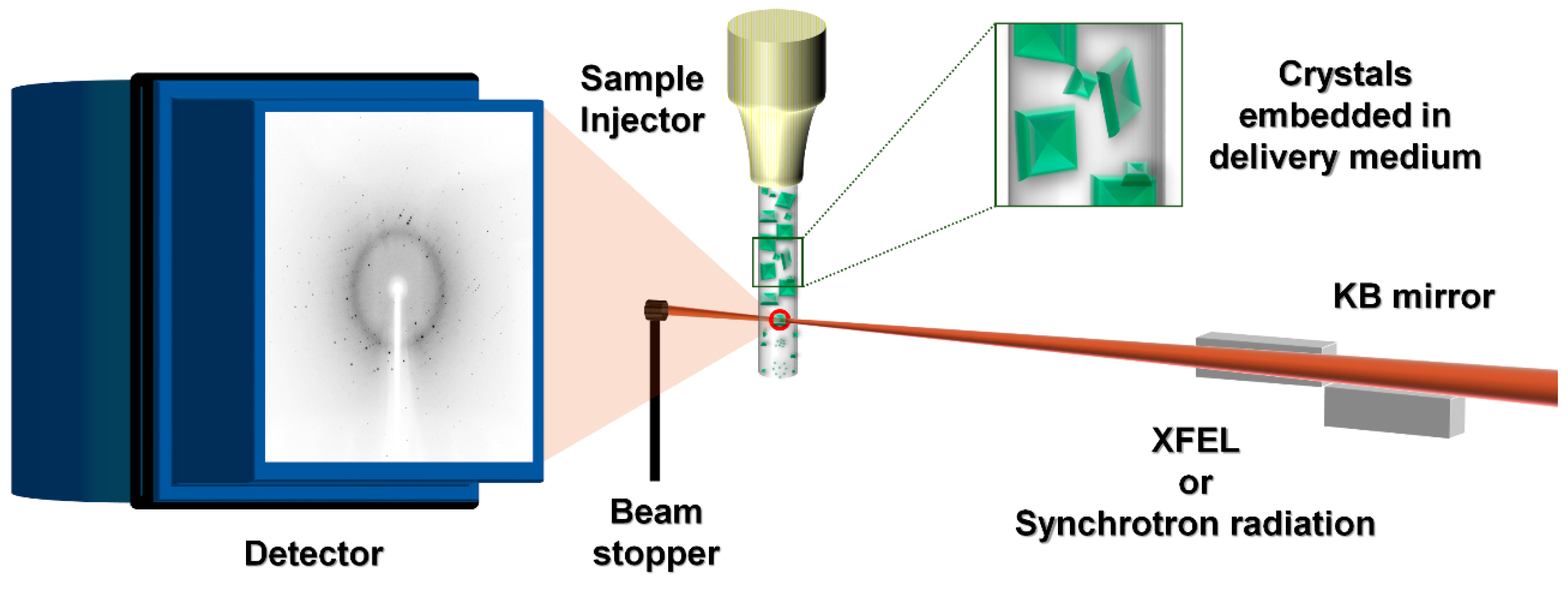
1. Introduction
2. Sample Preparation for the Crystals in Delivery Medium
2.1. Crystal Growth in Delivery Media
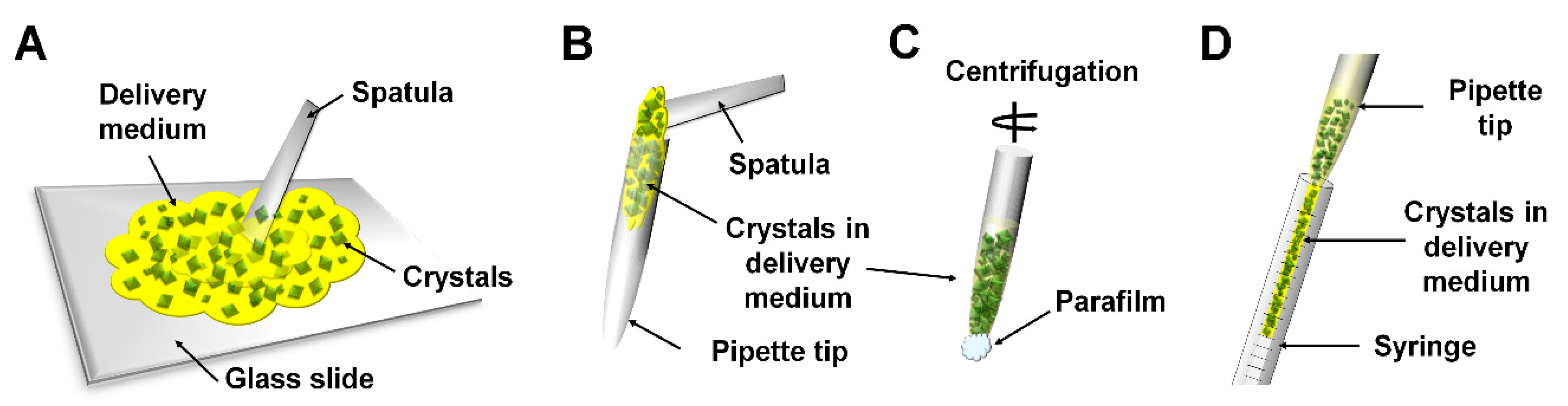
2.2. Manual Mixing
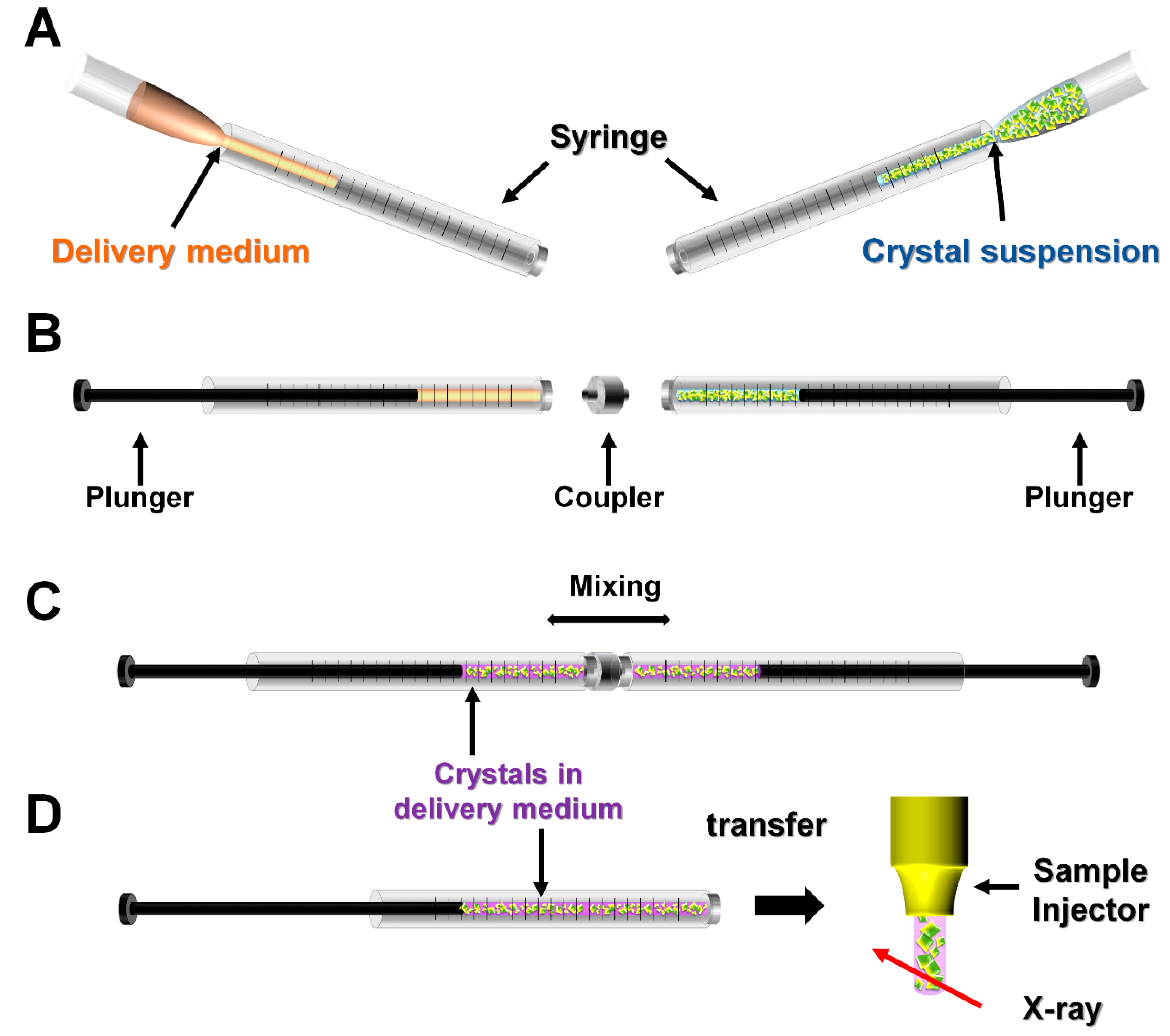
2.3. Mechanical Mixing
3. Sample Delivery Media and its Applications
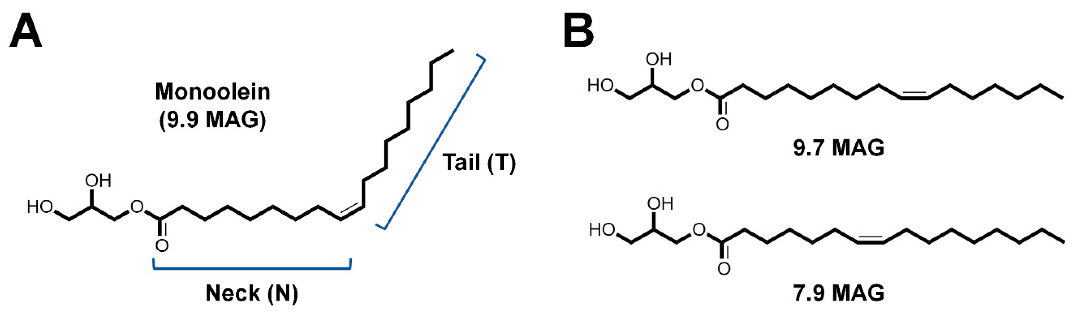
3.1. Lipidic Cubic Phase
3.2. Oil-Based Delivery Medium
3.2.1. Mineral Oil Grease
3.2.2. Vaseline (Petroleum Jelly)
3.2.3. Synthetic Grease Super Lube
3.2.4. Nuclear Grease
3.3. Hydrogel-Based Delivery Medium
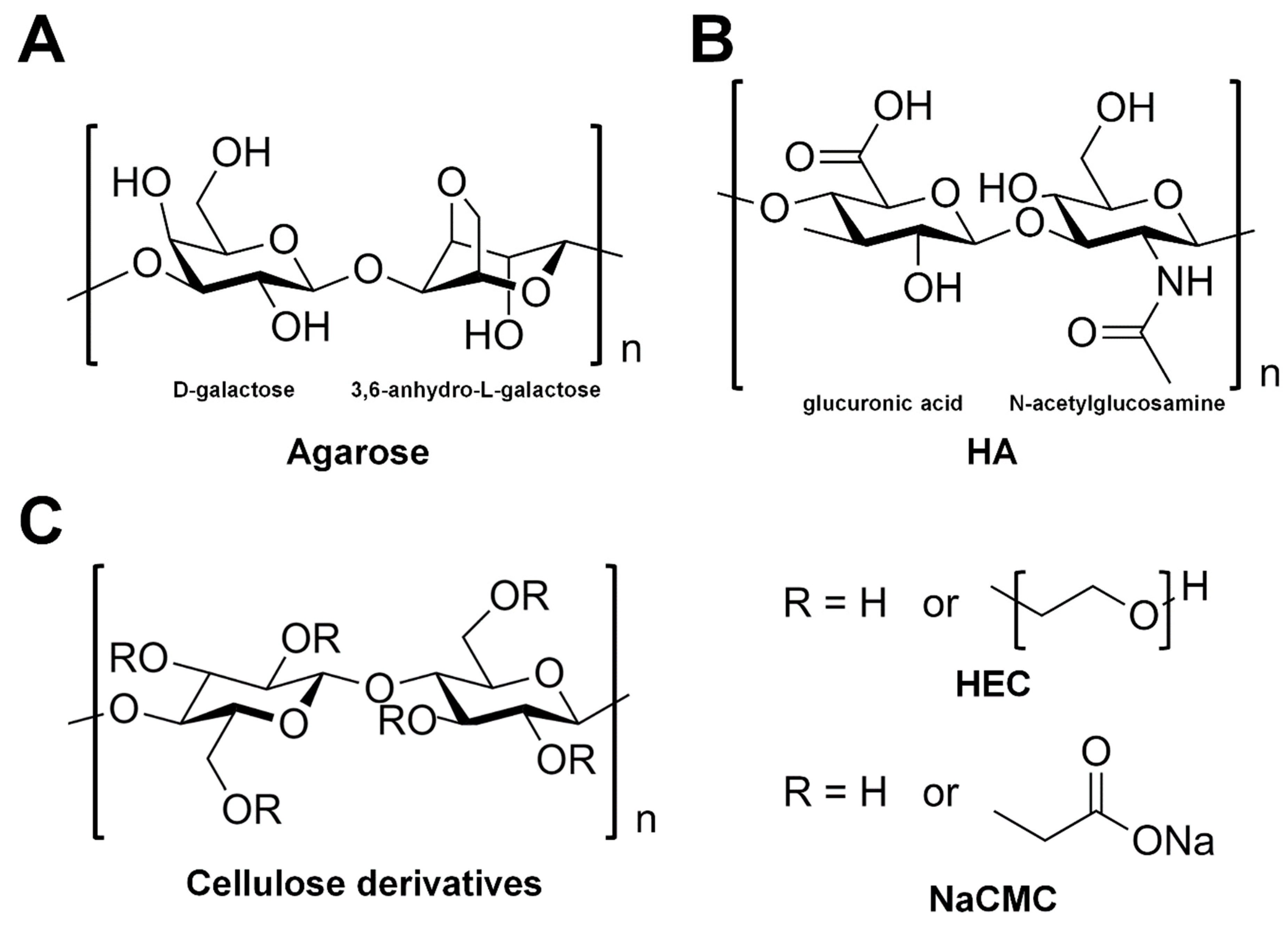
3.3.1. Agarose
3.3.2. Hyaluronic Acid
3.3.3. Hydroxyethyl Cellulose
3.3.4. Carboxymethyl Cellulose Sodium Salt
3.3.5. Pluronic F-127
3.3.6. Poly(ethylene oxide)
3.3.7. Polyacrylamide
4. Discussion
Funding
Conflicts of Interest
Abbreviations
| SFX | serial femtosecond crystallography |
| SMX | serial millisecond crystallography |
| SX | serial crystallography |
| XFEL | X-ray free electron laser |
| LCP | lipidic cubic phase |
| ID | inner diameter |
| OD | outer diameter |
| HA | hyaluronic acid |
| HEC | hydroxyethyl cellulose |
| NaCMC | carboxymethyl cellulose sodium salt |
| F-127 | pluronic F-127 |
| PEO | poly(ethylene oxide) |
| PAM | polyacrylamide |
References
- Su, X.D.; Zhang, H.; Terwilliger, T.C.; Liljas, A.; Xiao, J.; Dong, Y. Protein Crystallography from the Perspective of Technology Developments. Crystallogr. Rev. 2015, 21, 122–153. [Google Scholar] [CrossRef] [PubMed]
- Jaskolski, M.; Dauter, Z.; Wlodawer, A. A brief history of macromolecular crystallography, illustrated by a family tree and its Nobel fruits. FEBS J. 2014, 281, 3985–4009. [Google Scholar] [CrossRef] [PubMed]
- Blundell, T.L. Protein crystallography and drug discovery: Recollections of knowledge exchange between academia and industry. IUCrJ 2017, 4, 308–321. [Google Scholar] [CrossRef] [PubMed]
- Pomes, A.; Chruszcz, M.; Gustchina, A.; Minor, W.; Mueller, G.A.; Pedersen, L.C.; Wlodawer, A.; Chapman, M.D. 100 Years later: Celebrating the contributions of X-ray crystallography to allergy and clinical immunology. J. Allergy Clin. Immun. 2015, 136, 29–37. [Google Scholar] [CrossRef] [PubMed]
- Holton, J.M.; Frankel, K.A. The minimum crystal size needed for a complete diffraction data set. Acta Crystallogr. D Biol. Crystallogr. 2010, 66, 393–408. [Google Scholar] [CrossRef] [PubMed]
- Helliwell, J.R. Protein Crystal Perfection and the Nature of Radiation-Damage. J. Cryst. Growth 1988, 90, 259–272. [Google Scholar] [CrossRef]
- Lomb, L.; Barends, T.R.M.; Kassemeyer, S.; Aquila, A.; Epp, S.W.; Erk, B.; Foucar, L.; Hartmann, R.; Rudek, B.; Rolles, D.; et al. Radiation damage in protein serial femtosecond crystallography using an X-ray free-electron laser. Phys. Rev. B 2011, 84, 214111. [Google Scholar] [CrossRef] [PubMed]
- Chapman, H.N.; Fromme, P.; Barty, A.; White, T.A.; Kirian, R.A.; Aquila, A.; Hunter, M.S.; Schulz, J.; DePonte, D.P.; Weierstall, U.; et al. Femtosecond X-ray protein nanocrystallography. Nature 2011, 470, 73–77. [Google Scholar] [CrossRef] [PubMed]
- Nave, C.; Hill, M.A. Will reduced radiation damage occur with very small crystals? J. Synchrotron Radiat. 2005, 12, 299–303. [Google Scholar] [CrossRef] [PubMed]
- Roedig, P.; Duman, R.; Sanchez-Weatherby, J.; Vartiainen, I.; Burkhardt, A.; Warmer, M.; David, C.; Wagner, A.; Meents, A. Room-temperature macromolecular crystallography using a micro-patterned silicon chip with minimal background scattering. J. Appl. Crystallogr. 2016, 49, 968–975. [Google Scholar] [CrossRef] [PubMed]
- Warkentin, M.; Hopkins, J.B.; Badeau, R.; Mulichak, A.M.; Keefe, L.J.; Thorne, R.E. Global radiation damage: Temperature dependence, time dependence and how to outrun it. J. Synchrotron Radiat. 2013, 20, 7–13. [Google Scholar] [CrossRef] [PubMed]
- Weik, M.; Ravelli, R.B.G.; Kryger, G.; McSweeney, S.; Raves, M.L.; Harel, M.; Gros, P.; Silman, I.; Kroon, J.; Sussman, J.L. Specific chemical and structural damage to proteins produced by synchrotron radiation. Proc. Natl. Acad. Sci. USA 2000, 97, 623–628. [Google Scholar] [CrossRef] [PubMed]
- Meents, A.; Dittrich, B.; Gutmann, S. A new aspect of specific radiation damage: Hydrogen abstraction from organic molecules. J. Synchrotron Radiat. 2009, 16, 183–190. [Google Scholar] [CrossRef] [PubMed]
- Meents, A.; Gutmann, S.; Wagner, A.; Schulze-Briese, C. Origin and temperature dependence of radiation damage in biological samples at cryogenic temperatures. Proc. Natl. Acad. Sci. USA 2010, 107, 1094–1099. [Google Scholar] [CrossRef] [PubMed]
- Rodgers, D.W. Cryocrystallography. Structure 1994, 2, 1135–1140. [Google Scholar] [CrossRef]
- Watenpaugh, K.D. Macromolecular crystallography at cryogenic temperatures. Curr. Opin. Struc. Biol. 1991, 1, 1012–1015. [Google Scholar] [CrossRef]
- Owen, R.L.; Rudino-Pinera, E.; Garman, E.F. Experimental determination of the radiation dose limit for cryocooled protein crystals. Proc. Natl. Acad. Sci. USA 2006, 103, 4912–4917. [Google Scholar] [CrossRef] [PubMed]
- Fraser, J.S.; van den Bedem, H.; Samelson, A.J.; Lang, P.T.; Holton, J.M.; Echols, N.; Alber, T. Accessing protein conformational ensembles using room-temperature X-ray crystallography. Proc. Natl. Acad. Sci. USA 2011, 108, 16247–16252. [Google Scholar] [CrossRef] [PubMed]
- Fenwick, R.B.; van den Bedem, H.; Fraser, J.S.; Wright, P.E. Integrated description of protein dynamics from room-temperature X-ray crystallography and NMR. Proc. Natl. Acad. Sci. USA 2014, 111, E445–E454. [Google Scholar] [CrossRef] [PubMed]
- Weinert, T.; Olieric, N.; Cheng, R.; Brunle, S.; James, D.; Ozerov, D.; Gashi, D.; Vera, L.; Marsh, M.; Jaeger, K.; et al. Serial millisecond crystallography for routine room-temperature structure determination at synchrotrons. Nat. Commun. 2017, 8, 542. [Google Scholar] [CrossRef] [PubMed]
- Nango, E.; Royant, A.; Kubo, M.; Nakane, T.; Wickstrand, C.; Kimura, T.; Tanaka, T.; Tono, K.; Song, C.Y.; Tanaka, R.; et al. A three-dimensional movie of structural changes in bacteriorhodopsin. Science 2016, 354, 1552–1557. [Google Scholar] [CrossRef] [PubMed]
- Suga, M.; Akita, F.; Sugahara, M.; Kubo, M.; Nakajima, Y.; Nakane, T.; Yamashita, K.; Umena, Y.; Nakabayashi, M.; Yamane, T.; et al. Light-induced structural changes and the site of O=O bond formation in PSII caught by XFEL. Nature 2017, 543, 131–135. [Google Scholar] [CrossRef] [PubMed]
- Ullrich, J.; Rudenko, A.; Moshammer, R. Free-electron lasers: New avenues in molecular physics and photochemistry. Annu. Rev. Phys. Chem. 2012, 63, 635–660. [Google Scholar] [CrossRef] [PubMed]
- Fromme, P.; Spence, J.C.H. Femtosecond nanocrystallography using X-ray lasers for membrane protein structure determination. Curr. Opin. Struc. Biol. 2011, 21, 509–516. [Google Scholar] [CrossRef] [PubMed]
- Schlichting, I. Serial femtosecond crystallography: The first five years. IUCrJ 2015, 2, 246–255. [Google Scholar] [CrossRef] [PubMed]
- Martin-Garcia, J.M.; Conrad, C.E.; Coe, J.; Roy-Chowdhury, S.; Fromme, P. Serial femtosecond crystallography: A revolution in structural biology. Arch. Biochem. Biophys. 2016, 602, 32–47. [Google Scholar] [CrossRef] [PubMed]
- Kim, J.; Kim, H.Y.; Park, J.; Kim, S.; Kim, S.; Rah, S.; Lim, J.; Nam, K.H. Focusing X-ray free-electron laser pulses using Kirkpatrick-Baez mirrors at the NCI hutch of the PAL-XFEL. J. Synchrotron Radiat. 2018, 25, 289–292. [Google Scholar] [CrossRef] [PubMed]
- Neutze, R.; Wouts, R.; van der Spoel, D.; Weckert, E.; Hajdu, J. Potential for biomolecular imaging with femtosecond X-ray pulses. Nature 2000, 406, 752–757. [Google Scholar] [CrossRef] [PubMed]
- Barty, A.; Caleman, C.; Aquila, A.; Timneanu, N.; Lomb, L.; White, T.A.; Andreasson, J.; Arnlund, D.; Bajt, S.; Barends, T.R.M.; et al. Self-terminating diffraction gates femtosecond X-ray nanocrystallography measurements. Nat. Photonics 2012, 6, 35–40. [Google Scholar] [CrossRef] [PubMed]
- Johansson, L.C.; Stauch, B.; Ishchenko, A.; Cherezov, V. A Bright Future for Serial Femtosecond Crystallography with XFELs. Trends Biochem. Sci. 2017, 42, 749–762. [Google Scholar] [CrossRef] [PubMed]
- Spence, J.C.H. Approaches to time-resolved diffraction using an XFEL. Faraday Discuss. 2014, 171, 429–438. [Google Scholar] [CrossRef] [PubMed]
- Jung, Y.O.; Lee, J.H.; Kim, J.; Schmidt, M.; Moffat, K.; Srajer, V.; Ihee, H. Volume-conserving trans-cis isomerization pathways in photoactive yellow protein visualized by picosecond X-ray crystallography. Nat. Chem. 2013, 5, 212–220. [Google Scholar] [CrossRef] [PubMed]
- Emma, P.; Akre, R.; Arthur, J.; Bionta, R.; Bostedt, C.; Bozek, J.; Brachmann, A.; Bucksbaum, P.; Coffee, R.; Decker, F.J.; et al. First lasing and operation of an angstrom-wavelength free-electron laser. Nat. Photonics 2010, 4, 641–647. [Google Scholar] [CrossRef]
- Ishikawa, T.; Aoyagi, H.; Asaka, T.; Asano, Y.; Azumi, N.; Bizen, T.; Ego, H.; Fukami, K.; Fukui, T.; Furukawa, Y.; et al. A compact X-ray free-electron laser emitting in the sub-angstrom region. Nat. Photonics 2012, 6, 540–544. [Google Scholar] [CrossRef]
- Kang, H.S.; Min, C.K.; Heo, H.; Kim, C.; Yang, H.; Kim, G.; Nam, I.; Baek, S.Y.; Choi, H.J.; Mun, G.; et al. Hard X-ray free-electron laser with femtosecond-scale timing jitter. Nat. Photonics 2017, 11, 708–713. [Google Scholar] [CrossRef]
- Ko, I.S.; Kang, H.S.; Heo, H.; Kim, C.; Kim, G.; Min, C.K.; Yang, H.; Baek, S.Y.; Choi, H.J.; Mun, G.; et al. Construction and Commissioning of PAL-XFEL Facility. Appl. Sci. 2017, 7, 479. [Google Scholar] [CrossRef]
- Tschentscher, T.; Bressler, C.; Grunert, J.; Madsen, A.; Mancuso, A.P.; Meyer, M.; Scherz, A.; Sinn, H.; Zastrau, U. Photon Beam Transport and Scientific Instruments at the European XFEL. Appl. Sci. 2017, 7, 592. [Google Scholar] [CrossRef]
- Milne, C.J.; Schietinger, T.; Aiba, M.; Alarcon, A.; Alex, J.; Anghel, A.; Arsov, V.; Beard, C.; Beaud, P.; Bettoni, S.; et al. SwissFEL: The Swiss X-ray Free Electron Laser. Appl. Sci. 2017, 7, 720. [Google Scholar] [CrossRef]
- Nogly, P.; James, D.; Wang, D.; White, T.A.; Zatsepin, N.; Shilova, A.; Nelson, G.; Liu, H.; Johansson, L.; Heymann, M.; et al. Lipidic cubic phase serial millisecond crystallography using synchrotron radiation. IUCrJ 2015, 2, 168–176. [Google Scholar] [CrossRef] [PubMed]
- DePonte, D.P.; Weierstall, U.; Schmidt, K.; Warner, J.; Starodub, D.; Spence, J.C.H.; Doak, R.B. Gas dynamic virtual nozzle for generation of microscopic droplet streams. J. Phys. D Appl. Phys. 2008, 41, 195505. [Google Scholar] [CrossRef]
- Boutet, S.; Lomb, L.; Williams, G.J.; Barends, T.R.M.; Aquila, A.; Doak, R.B.; Weierstall, U.; DePonte, D.P.; Steinbrener, J.; Shoeman, R.L.; et al. High-Resolution Protein Structure Determination by Serial Femtosecond Crystallography. Science 2012, 337, 362–364. [Google Scholar] [CrossRef] [PubMed]
- Liu, W.; Ishchenko, A.; Cherezov, V. Preparation of microcrystals in lipidic cubic phase for serial femtosecond crystallography. Nat. Protoc. 2014, 9, 2123–2134. [Google Scholar] [CrossRef] [PubMed]
- Sierra, R.G.; Laksmono, H.; Kern, J.; Tran, R.; Hattne, J.; Alonso-Mori, R.; Lassalle-Kaiser, B.; Glockner, C.; Hellmich, J.; Schafer, D.W.; et al. Nanoflow electrospinning serial femtosecond crystallography. Acta Crystallogr. D Biol. Crystallogr. 2012, 68, 1584–1587. [Google Scholar] [CrossRef] [PubMed]
- Weierstall, U.; James, D.; Wang, C.; White, T.A.; Wang, D.J.; Liu, W.; Spence, J.C.H.; Doak, R.B.; Nelson, G.; Fromme, P.; et al. Lipidic cubic phase injector facilitates membrane protein serial femtosecond crystallography. Nat. Commun. 2014, 5, 3309. [Google Scholar] [CrossRef] [PubMed]
- Roessler, C.G.; Agarwal, R.; Allaire, M.; Alonso-Mori, R.; Andi, B.; Bachega, J.F.R.; Bommer, M.; Brewster, A.S.; Browne, M.C.; Chatterjee, R.; et al. Acoustic Injectors for Drop-On-Demand Serial Femtosecond Crystallography. Structure 2016, 24, 631–640. [Google Scholar] [CrossRef] [PubMed]
- Hunter, M.S.; Segelke, B.; Messerschmidt, M.; Williams, G.J.; Zatsepin, N.A.; Barty, A.; Benner, W.H.; Carlson, D.B.; Coleman, M.; Graf, A.; et al. Fixed-target protein serial microcrystallography with an X-ray free electron laser. Sci. Rep. 2014, 4, 6026. [Google Scholar] [CrossRef] [PubMed]
- Mueller, C.; Marx, A.; Epp, S.W.; Zhong, Y.; Kuo, A.; Balo, A.R.; Soman, J.; Schotte, F.; Lemke, H.T.; Owen, R.L.; et al. Fixed target matrix for femtosecond time-resolved and in situ serial micro-crystallography. Struct. Dyn. 2015, 2, 054302. [Google Scholar] [CrossRef] [PubMed]
- Oghbaey, S.; Sarracini, A.; Ginn, H.M.; Pare-Labrosse, O.; Kuo, A.; Marx, A.; Epp, S.W.; Sherrell, D.A.; Eger, B.T.; Zhong, Y.; et al. Fixed target combined with spectral mapping: Approaching 100% hit rates for serial crystallography. Acta Crystallogr. D Struct. Biol. 2016, 72, 944–955. [Google Scholar] [CrossRef] [PubMed]
- Roedig, P.; Ginn, H.M.; Pakendorf, T.; Sutton, G.; Harlos, K.; Walter, T.S.; Meyer, J.; Fischer, P.; Duman, R.; Vartiainen, I.; et al. High-speed fixed-target serial virus crystallography. Nat. Methods 2017, 14, 805–810. [Google Scholar] [CrossRef] [PubMed]
- Doak, R.B.; Nass Kovacs, G.; Gorel, A.; Foucar, L.; Barends, T.R.M.; Grunbein, M.L.; Hilpert, M.; Kloos, M.; Roome, C.M.; Shoeman, R.L.; et al. Crystallography on a chip—Without the chip: Sheet-on-sheet sandwich. Acta Crystallogr. D Biol. Crystallogr. 2018, 74, 1000–1007. [Google Scholar] [CrossRef] [PubMed]
- Muniyappan, S.; Kim, S.O.; Ihee, H. Recent Advances and Future Prospects of Serial Crystallography using XFEL and synchrotron X-ray sources. Biodesign 2015, 3, 98–110. [Google Scholar]
- Sugahara, M.; Mizohata, E.; Nango, E.; Suzuki, M.; Tanaka, T.; Masudala, T.; Tanaka, R.; Shimamura, T.; Tanaka, Y.; Suno, C.; et al. Grease matrix as a versatile carrier of proteins for serial crystallography. Nat. Methods 2015, 12, 61–63. [Google Scholar] [CrossRef] [PubMed]
- Botha, S.; Nass, K.; Barends, T.R.M.; Kabsch, W.; Latz, B.; Dworkowski, F.; Foucar, L.; Panepucci, E.; Wang, M.T.; Shoeman, R.L.; et al. Room-temperature serial crystallography at synchrotron X-ray sources using slowly flowing free-standing high-viscosity microstreams. Acta Crystallogr. D Biol. Crystallogr. 2015, 71, 387–397. [Google Scholar] [CrossRef] [PubMed]
- Conrad, C.E.; Basu, S.; James, D.; Wang, D.J.; Schaffer, A.; Roy-Chowdhury, S.; Zatsepin, N.A.; Aquila, A.; Coe, J.; Gati, C.; et al. A novel inert crystal delivery medium for serial femtosecond crystallography. IUCrJ 2015, 2, 421–430. [Google Scholar] [CrossRef] [PubMed]
- Sugahara, M.; Song, C.Y.; Suzuki, M.; Masuda, T.; Inoue, S.; Nakane, T.; Yumoto, F.; Nango, E.; Tanaka, R.; Tono, K.; et al. Oil-free hyaluronic acid matrix for serial femtosecond crystallography. Sci. Rep. 2016, 6, 24484. [Google Scholar] [CrossRef] [PubMed]
- Sugahara, M.; Nakane, T.; Masuda, T.; Suzuki, M.; Inoue, S.; Song, C.Y.; Tanaka, R.; Nakatsu, T.; Mizohata, E.; Yumoto, F.; et al. Hydroxyethyl cellulose matrix applied to serial crystallography. Sci. Rep. 2017, 7, 703. [Google Scholar] [CrossRef] [PubMed]
- Kovacsova, G.; Grunbein, M.L.; Kloos, M.; Barends, T.R.M.; Schlesinger, R.; Heberle, J.; Kabsch, W.; Shoeman, R.L.; Doak, R.B.; Schlichting, I. Viscous hydrophilic injection matrices for serial crystallography. IUCrJ 2017, 4, 400–410. [Google Scholar] [CrossRef] [PubMed]
- Lopez, C.G.; Rogers, S.E.; Colby, R.H.; Graham, P.; Cabral, J.T. Structure of Sodium Carboxymethyl Cellulose Aqueous Solutions: A SANS and Rheology Study. J. Polym. Sci. Pol. Phys. 2015, 53, 492–501. [Google Scholar] [CrossRef] [PubMed]
- Park, J.; Park, S.; Kim, J.; Park, G.; Cho, Y.; Nam, K.H. Polyacrylamide injection matrix for serial femtosecond crystallography. Sci. Rep. 2019, 9, 2525. [Google Scholar] [CrossRef] [PubMed]
- Ishchenko, A.; Peng, L.L.; Zinovev, E.; Vlasov, A.; Lee, S.C.; Kuklin, A.; Mishin, A.; Borshcheyskiy, V.; Zhang, Q.H.; Cherezov, V. Chemically Stable Lipids for Membrane Protein Crystallization. Cryst. Growth Des. 2017, 17, 3502–3511. [Google Scholar] [CrossRef] [PubMed]
- Cherezov, V. Lipidic cubic phase technologies for membrane protein structural studies. Curr. Opin Struc. Biol. 2011, 21, 559–566. [Google Scholar] [CrossRef] [PubMed]
- Caffrey, M. On the Mechanism of Membrane Protein Crystallization in Lipidic Mesophases. Cryst. Growth Des. 2008, 8, 4244–4254. [Google Scholar] [CrossRef]
- Ishchenko, A.; Cherezov, V.; Liu, W. Preparation and Delivery of Protein Microcrystals in Lipidic Cubic Phase for Serial Femtosecond Crystallography. J. Vis. Exp. 2016, 54463. [Google Scholar] [CrossRef] [PubMed]
- Gavira, J.A.; Garcia-Ruiz, J.M. Agarose as crystallisation media for proteins II: Trapping of gel fibres into the crystals. Acta Crystallogr. D Biol. Crystallogr. 2002, 58, 1653–1656. [Google Scholar] [CrossRef] [PubMed]
- Garcia-Ruiz, J.M.; Novella, M.L.; Moreno, R.; Gavira, J.A. Agarose as crystallization media for proteins I: Transport processes. J. Cryst. Growth 2001, 232, 165–172. [Google Scholar] [CrossRef]
- Lorber, B.; Sauter, C.; Theobald-Dietrich, A.; Moreno, A.; Schellenberger, P.; Robert, M.C.; Capelle, B.; Sanglier, S.; Potier, N.; Giege, R. Crystal growth of proteins, nucleic acids, and viruses in gels. Prog. Biophys. Mol. Biol. 2009, 101, 13–25. [Google Scholar] [CrossRef] [PubMed]
- Cheng, A.; Hummel, B.; Qiu, H.; Caffrey, M. A simple mechanical mixer for small viscous lipid-containing samples. Chem. Phys. Lipids 1998, 95, 11–21. [Google Scholar] [CrossRef]
- Caffrey, M.; Cherezov, V. Crystallizing membrane proteins using lipidic mesophases. Nat. Protoc. 2009, 4, 706–731. [Google Scholar] [CrossRef] [PubMed]
- Fromme, R.; Ishchenko, A.; Metz, M.; Chowdhury, S.R.; Basu, S.; Boutet, S.; Fromme, P.; White, T.A.; Barty, A.; Spence, J.C.H.; et al. Serial femtosecond crystallography of soluble proteins in lipidic cubic phase. IUCrJ 2015, 2, 545–551. [Google Scholar] [CrossRef] [PubMed]
- Martin-Garcia, J.M.; Conrad, C.E.; Nelson, G.; Stander, N.; Zatsepin, N.A.; Zook, J.; Zhu, L.; Geiger, J.; Chun, E.; Kissick, D.; et al. Serial millisecond crystallography of membrane and soluble protein microcrystals using synchrotron radiation. IUCrJ 2017, 4, 439–454. [Google Scholar] [CrossRef] [PubMed]
- Caffrey, M. Membrane protein crystallization. J. Struct. Biol. 2003, 142, 108–132. [Google Scholar] [CrossRef]
- Kulkarni, C.V.; Wachter, W.; Iglesias-Salto, G.; Engelskirchen, S.; Ahualli, S. Monoolein: A magic lipid? Phys. Chem. Chem. Phys. 2011, 13, 3004–3021. [Google Scholar] [CrossRef] [PubMed]
- Li, D.F.; Shah, S.T.A.; Caffrey, M. Host Lipid and Temperature as Important Screening Variables for Crystallizing Integral Membrane Proteins in Lipidic Mesophases. Trials with Diacylglycerol Kinase. Cryst. Growth Des. 2013, 13, 2846–2857. [Google Scholar] [CrossRef] [PubMed]
- Li, D.F.; Howe, N.; Dukkipati, A.; Shah, S.T.A.; Bax, B.D.; Edge, C.; Bridges, A.; Hardwicke, P.; Singh, O.M.P.; Giblin, G.; et al. Crystallizing Membrane Proteins in the Lipidic Mesophase. Experience with Human Prostaglandin E2 Synthase 1 and an Evolving Strategy. Cryst. Growth Des. 2014, 14, 2034–2047. [Google Scholar] [CrossRef] [PubMed]
- Ahmed, E.M. Hydrogel: Preparation, characterization, and applications: A review. J. Adv. Res. 2015, 6, 105–121. [Google Scholar] [CrossRef] [PubMed]
- Iwata, H.; Takagi, T.; Amemiya, H.; Shimizu, H.; Yamashita, K.; Kobayashi, K.; Akutsu, T. Agarose for a Bioartificial Pancreas. J. Biomed. Mater. Res. 1992, 26, 967–977. [Google Scholar] [CrossRef] [PubMed]
- Normand, V.; Lootens, D.L.; Amici, E.; Plucknett, K.P.; Aymard, P. New insight into agarose gel mechanical properties. Biomacromolecules 2000, 1, 730–738. [Google Scholar] [CrossRef] [PubMed]
- Kakehi, K.; Kinoshita, M.; Yasueda, S. Hyaluronic acid: Separation and biological implications. J. Chromatogr. B 2003, 797, 347–355. [Google Scholar] [CrossRef]
- Pan, Y.; Liu, Y.H.; Lu, X.C.; Pan, G.S.; Luo, J.B. The Role of Hydroxyethyl Cellulose (HEC) in the Chemical Mechanical Planarization of Copper. J. Electrochem. Soc. 2012, 159, H329–H334. [Google Scholar] [CrossRef]
- Guzman, M.; Aberturas, M.R.; Garcia, F.; Molpeceres, J. Gelatin Gels and Polyoxyethylene-Polyoxypropylene Gels—Comparative-Study of Their Properties. Drug Dev. Ind. Pharm. 1994, 20, 2041–2048. [Google Scholar]
- Miyazaki, S.; Takeuchi, S.; Yokouchi, C.; Takada, M. Pluronic F-127 Gels as a Vehicle for Topical Administration of Anticancer Agents. Chem. Pharm. Bull. 1984, 32, 4205–4208. [Google Scholar] [CrossRef] [PubMed]
- Escobar-Chavez, J.J.; Lopez-Cervantes, M.; Naik, A.; Kalia, Y.N.; Quintanar-Guerrero, D.; Ganem-Quintanar, A. Applications of thermo-reversible pluronic F-127 gels in pharmaceutical formulations. J. Pharm. Pharm. Sci. 2006, 9, 339–358. [Google Scholar] [PubMed]
- Raymond, S.; Weintraub, L. Acrylamide Gel as a Supporting Medium for Zone Electrophoresis. Science 1959, 130, 711. [Google Scholar] [CrossRef] [PubMed]
- Hendrickson, E.R.; Neuman, R.D. Determination of Polyacrylamide by Spectrofluorometry. Anal. Chem 1984, 56, 354–357. [Google Scholar] [CrossRef]
- Chrambach, A.; Rodbard, D. Polyacrylamide Gel Electrophoresis. Science 1971, 172, 440–451. [Google Scholar] [CrossRef] [PubMed]
- Arndt, C.; Koristka, S.; Bartsch, H.; Bachmann, M. Native polyacrylamide gels. Methods Mol. Biol. 2012, 869, 49–53. [Google Scholar] [PubMed]
- Haupert, L.M.; Simpson, G.J. Screening of protein crystallization trials by second order nonlinear optical imaging of chiral crystals (SONICC). Methods 2011, 55, 379–386. [Google Scholar] [CrossRef] [PubMed]
- Kissick, D.J.; Wanapun, D.; Simpson, G.J. Second-order nonlinear optical imaging of chiral crystals. Annu. Rev. Anal. Chem. 2011, 4, 419–437. [Google Scholar] [CrossRef] [PubMed]


© 2019 by the author. Licensee MDPI, Basel, Switzerland. This article is an open access article distributed under the terms and conditions of the Creative Commons Attribution (CC BY) license (http://creativecommons.org/licenses/by/4.0/).
Share and Cite
Nam, K.H. Sample Delivery Media for Serial Crystallography. Int. J. Mol. Sci. 2019, 20, 1094. https://doi.org/10.3390/ijms20051094
Nam KH. Sample Delivery Media for Serial Crystallography. International Journal of Molecular Sciences. 2019; 20(5):1094. https://doi.org/10.3390/ijms20051094
Chicago/Turabian StyleNam, Ki Hyun. 2019. "Sample Delivery Media for Serial Crystallography" International Journal of Molecular Sciences 20, no. 5: 1094. https://doi.org/10.3390/ijms20051094
APA StyleNam, K. H. (2019). Sample Delivery Media for Serial Crystallography. International Journal of Molecular Sciences, 20(5), 1094. https://doi.org/10.3390/ijms20051094