Towards Unraveling the Histone Code by Fragment Blind Docking


Abstract

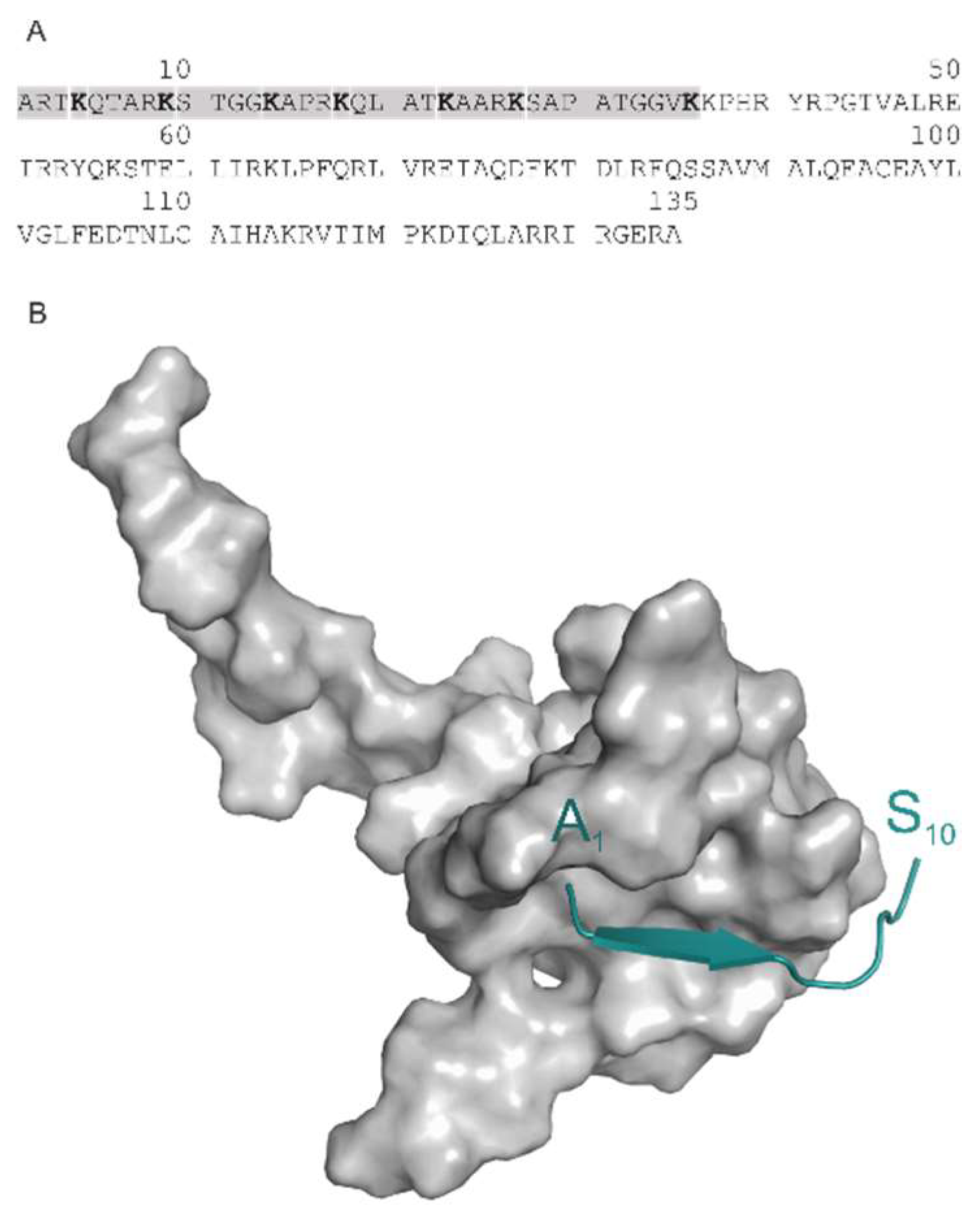
1. Introduction
2. Results and Discussion
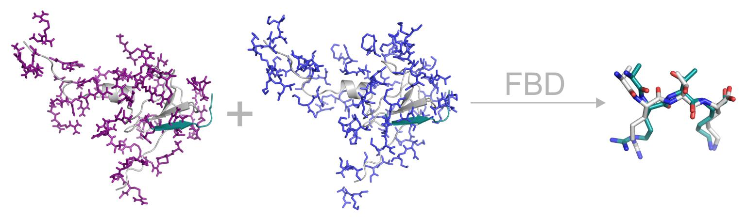
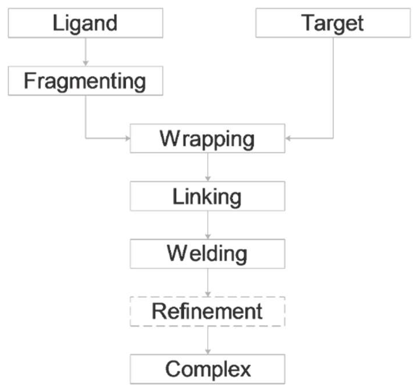
2.1. Fragmenting
2.2. Wrapping
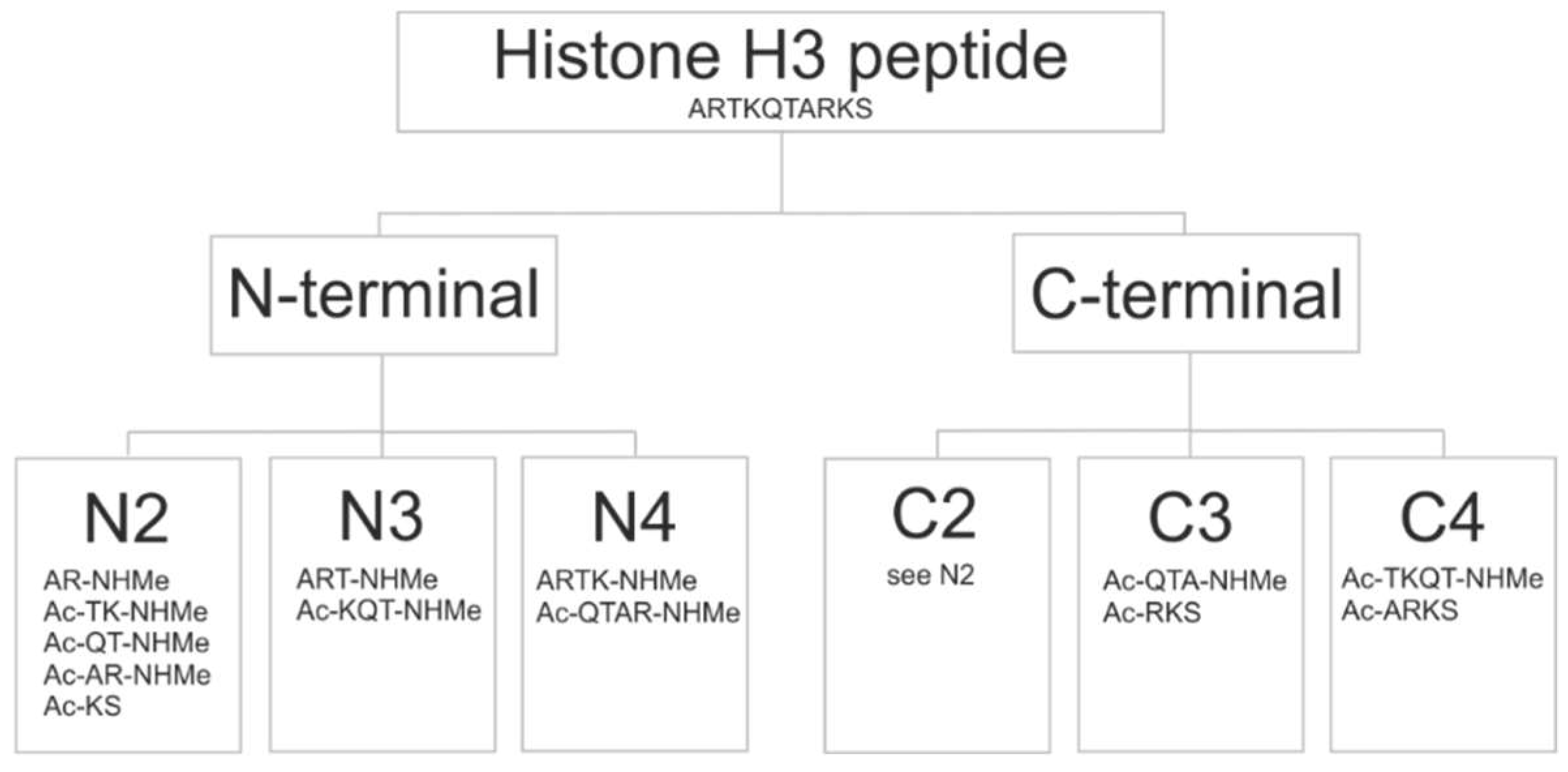
2.3. Fragment Size
2.4. Chemistry of Binding
2.5. Secondary Structure of the Ligand.
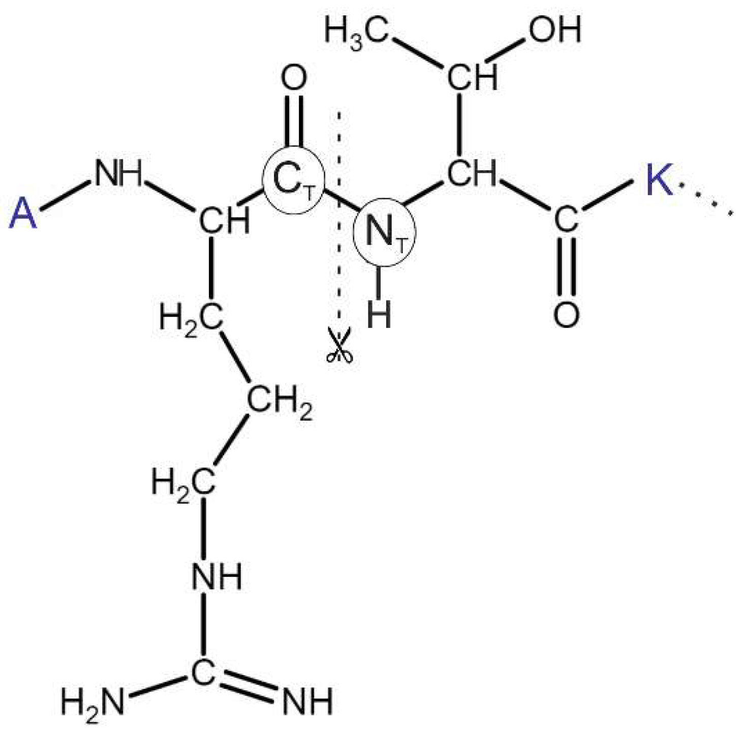
2.6. Fragment Ends
2.7. Linking
2.8. Welding and Refinement.
3. Methods
3.1. Wrapping
3.1.1. Preparation of Targets
3.1.2. Preparation of Ligands
3.1.3. Grid maps and Blind Docking Parameters
3.1.4. Wrapping Cycles
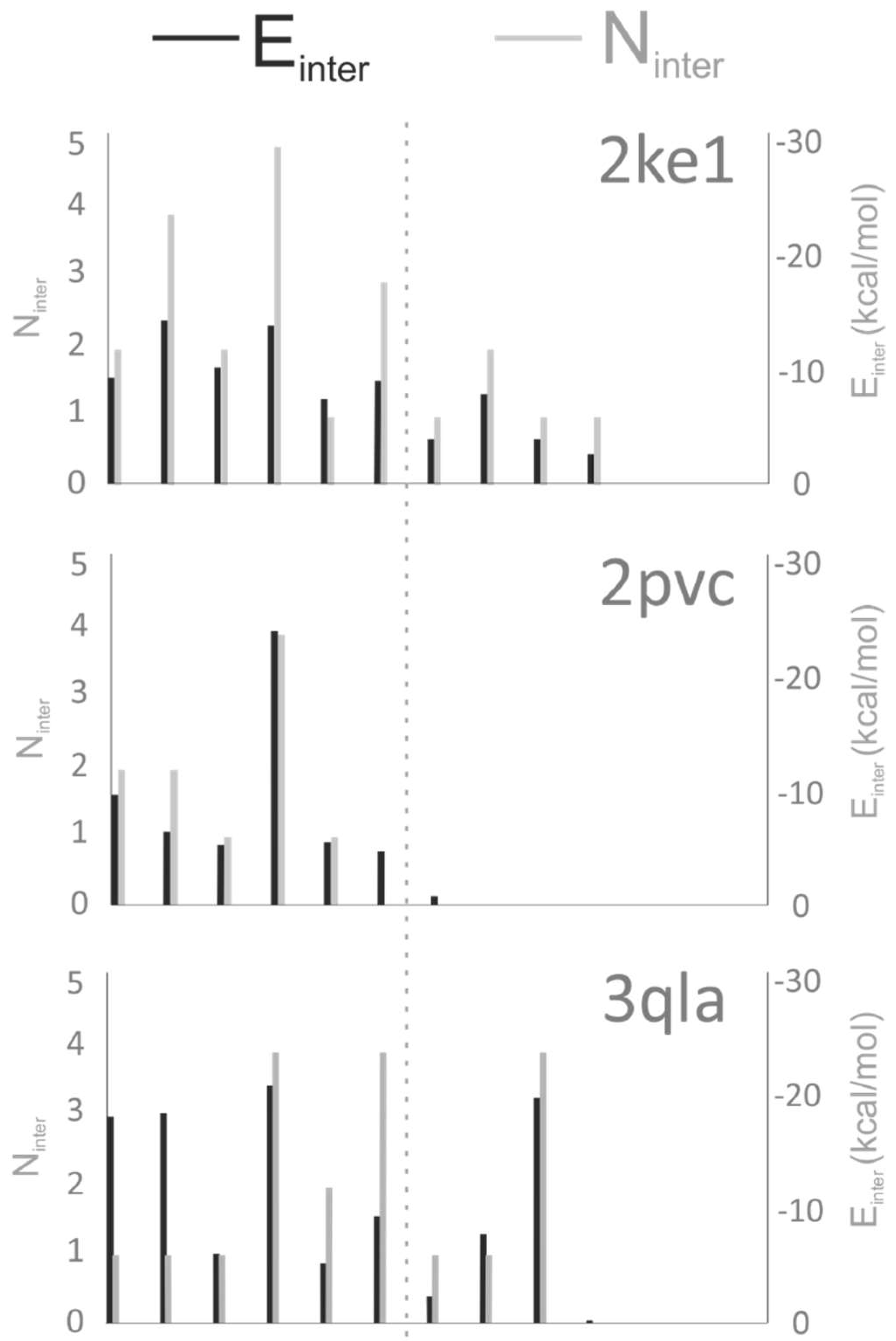
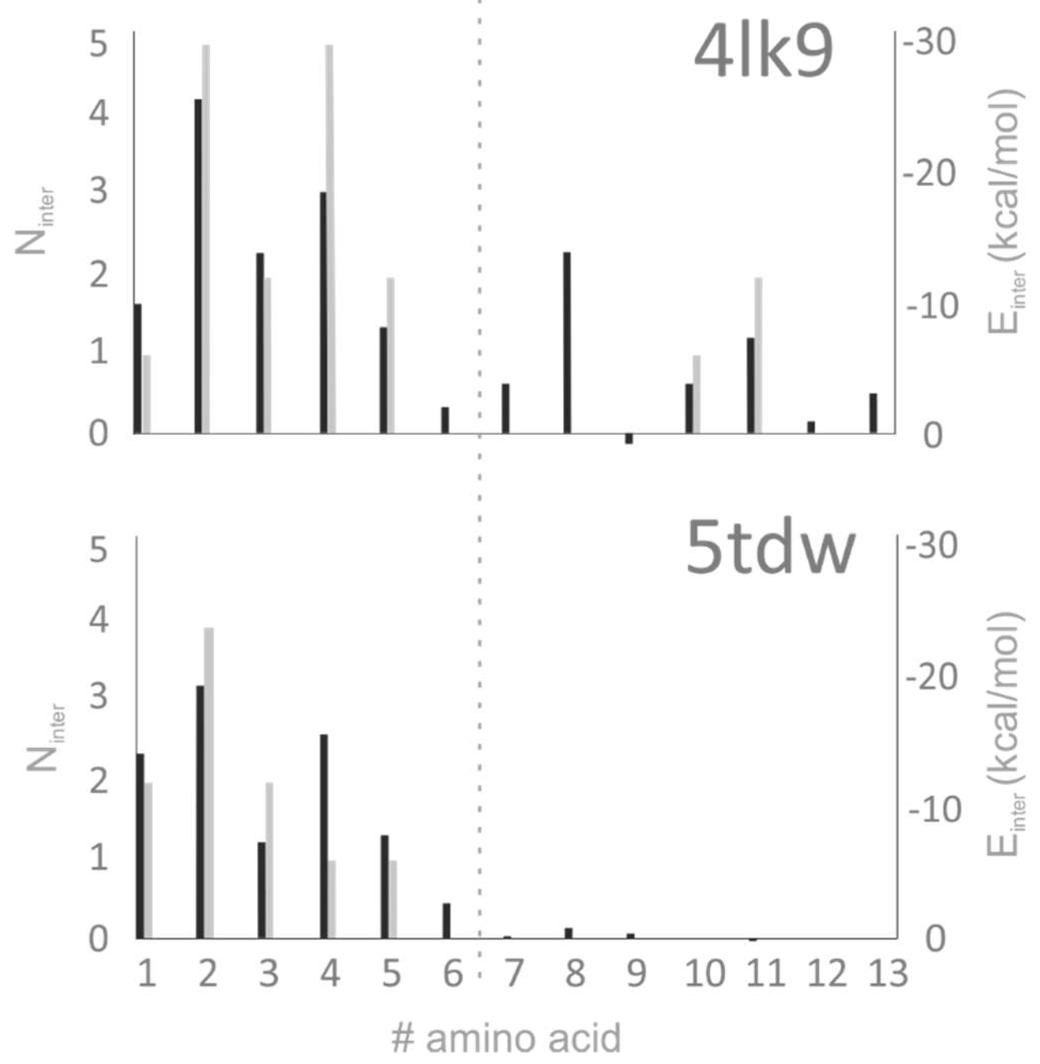
3.2. Analysis of Target–Ligand Interactions
3.2.1. Preparation of the Target–Ligand Complexes
3.2.2. Number of Intermolecular Interactions (Ninter)
3.2.3. Target–Ligand Intermolecular Interaction Energy (Einter)
3.3. Linking and Welding
4. Conclusions
Supplementary Materials
Author Contributions
Funding
Conflicts of Interest
References
- Desjarlais, R.; Tummino, P.J. The Role of Histone-modifying Enzymes and their Complexes in Regulation of Chromatin Biology. Biochemistry 2016, 55, 1584–1599. [Google Scholar] [CrossRef] [PubMed]
- Portela, A.; Esteller, M. Epigenetic modifications and human disease. Nat. Biotechnol. 2010, 28, 1057–1068. [Google Scholar] [CrossRef] [PubMed]
- Rodenhiser, D.; Mann, M. Epigenetics and human disease: Translating basic biology into clinical applications. Can. Med. Assoc. J. 2006, 174, 341. [Google Scholar] [CrossRef] [PubMed]
- Taverna, S.D.; Li, H.; Ruthenburg, A.J.; Allis, C.D.; Patel, D.J. How chromatin-binding modules interpret histone modifications: Lessons from professional pocket pickers. Nat. Struct. Mol. Biol. 2007, 14, 1025–1040. [Google Scholar] [CrossRef] [PubMed]
- Catherine, A. Musselman, Marie-Eve Lalonde, Jacques Côté2 and TGK. Readers, Perceiving the epigenetic landscape through histone Catherine. Nat. Struct. Mol. Biol. 2012, 19, 1218–1227. [Google Scholar]
- Strahl, B.D.; Allis, C.D. The language of covalent histone modifications. Nature 2000, 403, 41–45. [Google Scholar] [CrossRef] [PubMed]
- Jenuwein, T.; Allis, C.D. Translating the Histone Code. Science 2001, 293, 1074–1081. [Google Scholar] [CrossRef]
- Davis, A.M.; Teague, S.J.; Kleywegt, G.J. Application and Limitations of X-ray Crystallographic Data in Structure-Based Ligand and Drug Design. Angew. Chem. 2003, 42, 2718–2736. [Google Scholar] [CrossRef]
- Blundell, T.L.; Jhoti, H.; Abell, C. High-Throughput crystallography for lead discovery in drug design. Nat. Rev. Drug Discov. 2002, 1, 45–54. [Google Scholar] [CrossRef]
- Saladin, A.; Rey, J.; Thévenet, P.; Zacharias, M.; Moroy, G.; Tufféry, P. PEP-SiteFinder: A tool for the blind identification of peptide binding sites on protein surfaces. Nucleic Acids Res. 2014, 42, W221–W226. [Google Scholar] [CrossRef]
- Yan, C.; Xu, X.; Zou, X. Fully Blind Docking at the Atomic Level for Protein-Peptide Complex Structure Prediction. Structure 2016, 24, 1842–1853. [Google Scholar] [CrossRef] [PubMed]
- Rentzsch, R.; Renard, B.Y. Docking small peptides remains a great challenge: An assessment using AutoDock Vina. Brief Bioinform. 2015, 16, 1045–1056. [Google Scholar] [CrossRef]
- Joseph-McCarthy, D.; Campbell, A.J.; Kern, G.; Moustakas, D. Fragment-Based Lead Discovery and Design. J. Chem. Inf. Model. 2014, 54, 693–704. [Google Scholar] [CrossRef] [PubMed]
- Liao, J.; Wang, Y.-T.; Lin, C.S. A fragment-based docking simulation for investigating peptide–protein bindings. Phys. Chem. Chem. Phys. 2017, 19, 10436–10442. [Google Scholar] [CrossRef] [PubMed]
- Taylor, R.D.; Jewsbury, P.J.; Essex, J.W. A review of protein-small molecule docking methods. J. Comput. Aided Mol. Des. 2002, 16, 151–166. [Google Scholar] [CrossRef]
- Hetényi, C.; van der Spoel, D. Efficient docking of peptides to proteins without prior knowledge of the binding site. Protein Sci. 2002, 11, 1729–1737. [Google Scholar] [CrossRef] [PubMed]
- Hetényi, C.; Van Der Spoel, D. Blind docking of drug-sized compounds to proteins with up to a thousand residues. FEBS Lett. 2006, 580, 1447–1450. [Google Scholar] [CrossRef]
- Hetényi, C.; Van Der Spoel, D. Toward prediction of functional protein pockets using blind docking and pocket search algorithms. Protein Sci. 2011, 20, 880–893. [Google Scholar] [CrossRef]
- Bálint, M.; Jeszenői, N.; Horváth, I.; van der Spoel, D.; Hetényi, C. Systematic exploration of multiple drug binding sites. J. Cheminform. 2017, 9, 65. [Google Scholar] [CrossRef]
- Berman, H.M.; Westbrook, J.; Feng, Z.; Gilliland, G.; Bhat, T.N.; Weissig, H.; Shindyalov, I.N.; Bourne, P.E. The Protein Data Bank. Nucleic Acids Res. 2000, 28, 235–242. [Google Scholar] [CrossRef]
- Chignola, F.; Gaetani, M.; Rebane, A.; Mollica, L.; Zucchelli, C.; Spitaleri, A.; Mannella, V.; Peterson, P.; Musco, G. The solution structure of the first PHD finger of autoimmune regulator in complex with non-modified histone H3 tail reveals the antagonistic role of H3R2 methylation. Nucleic Acids Res. 2009, 37, 2951–2961. [Google Scholar] [CrossRef] [PubMed]
- Li, H.; Lu, L.; Chen, R.; Quan, L.; Xia, X.; Lü, Q. PaFlexPepDock: Parallel Ab-initio docking of peptides onto their receptors with full flexibility based on Rosetta. PLoS ONE 2014, 9, e94769. [Google Scholar] [CrossRef] [PubMed]
- Verschueren, E.; Vanhee, P.; Rousseau, F.; Schymkowitz, J.; Serrano, L. Protein-peptide complex prediction through fragment interaction patterns. Structure 2013, 21, 789–797. [Google Scholar] [CrossRef] [PubMed]
- Morris, G.M.; Goodsell, D.S.; Halliday, R.S.; Huey, R.; Hart, W.E.; Belew, R.K.; Olson, A.J. Automated Docking Using a Lamarckian Genetic Algorithm and an Empirical Binding Free Energy Function. J. Comput. Chem. 1998, 19, 1639–1662. [Google Scholar] [CrossRef]
- Morris, G.M.; Huey, R.; Lindstrom, W.; Sanner, M.F.; Belew, R.K.; Goodsell, D.S.; Olson, A.J. AutoDock4 and AutoDockTools4: Automated Docking with Selective Receptor Flexibility. J. Comput. Chem. 2009, 28, 73–86. [Google Scholar] [CrossRef] [PubMed]
- Guex, N.; Peitsch, M.C.; Schwede, T. Automated comparative protein structure modeling with SWISS-MODEL and Swiss-PdbViewer: A historical perspective. Electrophoresis 2009, 30 (Suppl. 1), 162–173. [Google Scholar] [CrossRef] [PubMed]
- Abraham, M.J.; Murtola, T.; Schulz, R.; Páll, S.; Smith, J.C.; Hess, B.; Lindahl, E. Gromacs: High performance molecular simulations through multi-level parallelism from laptops to supercomputers. SoftwareX 2015, 1–2, 19–25. [Google Scholar] [CrossRef]
- Lindorff-Larsen, K.; Piana, S.; Palmo, K.; Maragakis, P.; Klepeis, J.L.; Dror, R.O.; Shaw, D.E. Improved side-chain torsion potentials for the Amber ff99SB protein force field. Proteins Struct. Funct. Bioinform. 2010, 78, 1950–1958. [Google Scholar] [CrossRef]
- Jorgensen, W.L.; Maxwell, D.S.; Tirado-Rives, J. Development and testing of the OPLS all-atom force field on conformational energetics and properties of organic liquids. J. Am. Chem. Soc. 1996, 118, 11225–11236. [Google Scholar] [CrossRef]
- Pappu, R.V.; Hart, R.K.; Ponder, J.W. Analysis and Application of Potential Energy Smoothing and Search Methods for Global Optimization. J. Phys. Chem. B 1998, 102, 9725–9742. [Google Scholar] [CrossRef]
- Wang, J.; Cieplak, P.; Li, J.; Cai, Q.; Hsieh, M.J.; Luo, R.; Duan, Y. Development of polarizable models for molecular mechanical calculations. 4. van der waals parametrization. J. Phys. Chem. B 2012, 116, 7088–7101. [Google Scholar] [CrossRef] [PubMed]
- Maestro, Schrödinger LLC: New York, NY, USA, 2017. Available online: https://www.schrodinger.com/maestro (accessed on 17 December 2018).
- Boyle, N.M.O.; Banck, M.; James, C.A.; Morley, C.; Vandermeersch, T.; Hutchison, G.R. Open Babel: An open chemical toolbox. J. Cheminform. 2011, 3, 1–14. [Google Scholar] [CrossRef] [PubMed]
- Halgren, T.A. Merck Molecular Force Field, I. Basis, Form, Scope, Parameterization, and Performance of MMFF94. J. Comput. Chem. 1996, 17, 490–519. [Google Scholar] [CrossRef]
- Huey, R. GMM AutoDock Tools 1.5.7. Available online: http://mgltools.scripps.edu/downloads (accessed on 17 December 2018).
- Gasteiger, J.; Marsili, M. Iterative partial equalization of orbital electronegativity-a rapid access to atomic charges. Tetrahedron 1980, 36, 3219–3228. [Google Scholar] [CrossRef]
- Mehler, E.L.; Solmajer, T. Electrostatic effects in proteins: Comparison of dielectric and charge models. Prot. Eng. 1991, 4, 903–910. [Google Scholar] [CrossRef]


| PDB ID | Target | Ligand (Histone H3 Peptide) * |
|---|---|---|
| 2ke1 | autoimmune regulator protein plant homeodomain (AIRE-PHD) | ARTKQTARKS |
| 2pvc | DNA (cytosine-5)-methyltransferase 3-like (DNMT3L) | ARTKQTA |
| 3qla | transcriptional regulator ATRX-ADD domain (ATRX-DNMT3-DNMT3L) | ARTKQTARK(Me3)S |
| 4lk9 | histone acetyltransferase KAT6A | ARTKQTARKSTGG |
| 5tdw | Set domain containing protein 3 | ARTK(Me3)QTARKST |
| System | Fragment Type | Fragment Sequence | #Cycle | #Rank | RMSD (Å) |
|---|---|---|---|---|---|
| 2ke1 | N2 = C2 | AR-NHMe | 1 | 4 | 1.9 |
| N2 = C2 | Ac-TK-NHMe | 1 | 1 | 2.8 | |
| N3 | Ac-KQT-NHMe | 1 | 1 | 2.4 | |
| 2pvc | N2 | AR-NHMe | 2 | 5 | 3.2 |
| N2 | Ac-TK-NHMe | 1 | 3 | 2.8 | |
| N3 | Ac-KQTA | 1 | 1 | 3.0 | |
| C2 | Ac-KQ-NHMe | 1 | 2 | 1.7 | |
| 3qla | N2 = C2 | Ac-QT-NHMe | 1 | 12 | 2.0 |
| N2 = C2 | Ac-K(Me3)S | 1 | 2 | 3.7 | |
| N4 | ARTK-NHMe | 1 | 1 | 3.3 | |
| 4lk9 | N2 | AR-NHMe | 1 | 1 | 2.9 |
| N2 | Ac-TK-NHMe | 1 | 4 | 4.0 | |
| 5tdw | N2 | AR-NHMe | 1 | 1 | 1.7 |
| Symbol | Description |
|---|---|
| dall | Smallest distance calculated between all heavy atoms |
| call | Collision matrix between any heavy atoms |
| dCN | Distance calculated between CT and NT atoms |
| cCN | Collision matrix from dCN, cCN = 1 if there is no collision, otherwise 0 |
| tCN | Trimming matrix from dCN, tCN = 0 if trimmed, otherwise 1 |
| fCN | Filtering matrix from the collision and trimming matrices, fCN = 1 if cCN = tCN = 1, otherwise 0 |
© 2019 by the authors. Licensee MDPI, Basel, Switzerland. This article is an open access article distributed under the terms and conditions of the Creative Commons Attribution (CC BY) license (http://creativecommons.org/licenses/by/4.0/).
Share and Cite
Bálint, M.; Horváth, I.; Mészáros, N.; Hetényi, C. Towards Unraveling the Histone Code by Fragment Blind Docking. Int. J. Mol. Sci. 2019, 20, 422. https://doi.org/10.3390/ijms20020422
Bálint M, Horváth I, Mészáros N, Hetényi C. Towards Unraveling the Histone Code by Fragment Blind Docking. International Journal of Molecular Sciences. 2019; 20(2):422. https://doi.org/10.3390/ijms20020422
Chicago/Turabian StyleBálint, Mónika, István Horváth, Nikolett Mészáros, and Csaba Hetényi. 2019. "Towards Unraveling the Histone Code by Fragment Blind Docking" International Journal of Molecular Sciences 20, no. 2: 422. https://doi.org/10.3390/ijms20020422
APA StyleBálint, M., Horváth, I., Mészáros, N., & Hetényi, C. (2019). Towards Unraveling the Histone Code by Fragment Blind Docking. International Journal of Molecular Sciences, 20(2), 422. https://doi.org/10.3390/ijms20020422