Article

Ti-Supported Oxide Coatings Based on MWO4 (M = Fe, Co, Ni): Plasma Electrolytic Synthesis, Characterization and Catalytic Properties in S, N-Heterocycles Peroxide Oxidation

by
Irina G. Tarkhanova
1,*,
Vladimir M. Zelikman
1,
Irina V. Lukiyanchuk
2,
Marina S. Vasilyeva
2,3,
Vladimir V. Tkachev
3,
Vladimir V. Korochentsev
2 and
Daria H. Shlyk
2
1
Department of Chemistry, Lomonosov Moscow State University, Leninskiye Gory, 1/3, Moscow 119991, Russia
2
Institute of Chemistry, Far Eastern Branch, Russian Academy of Sciences, 100-letya Vladivostoka Prosp., 159, Vladivostok 690022, Russia
3
Department of Natural Sciences, Far Eastern Federal University, FEFU Campus 10, Ajax Bay, Russky Island, Vladivostok 690922, Russia
*
Author to whom correspondence should be addressed.
Molecules 2025, 30(9), 1998; https://doi.org/10.3390/molecules30091998
Submission received: 25 March 2025 / Revised: 15 April 2025 / Accepted: 24 April 2025 / Published: 30 April 2025
(This article belongs to the Section Materials Chemistry)

Abstract

:
In this study, catalytically active coatings on titanium were synthesized by plasma electrolytic oxidation (PEO) in aqueous electrolytes based on sodium tungstate with the addition of sodium phosphate or sodium borate and chelate complexes of iron, cobalt or nickel. Taking into account the EDX, XPS and XRD data, the oxide–phosphate coatings (PWFe, PWCo, PWNi) contained crystalline titanium oxide and amorphous tungstates and/or phosphates of iron triad metals. Amorphization was facilitated by high phosphorus concentrations (up to 6 at.%). Replacing phosphate with borate in the electrolyte with Ni(II)-EDTA complexes led to the crystallization of WO3 and NiWO4 in the PEO coatings (BWNi). All formed PEO coatings were active in reactions of the oxidative desulfurization (ODS) of thiophene and dibenzothiophene and oxidative denitrogenation (ODN) of pyridine, as well as in the simultaneous removal of S- and N-containing substrates from their mixture. The stability of samples with MWO4 increased in the following series: PWNi < PWCo < PW < PWFe < BWNi. Replacing phosphate with borate in the electrolyte resulted in the preparation of catalysts with enhanced stability and activity. In contrast to PWM catalysts, the BWNi catalyst had selectivity toward the oxidation of pyridine in its mixture with thiophene.

Graphical Abstract

1. Introduction

Plasma electrolytic oxidation (PEO) generates oxide layers on the surface of metals and alloys [1,2,3,4,5]. Under electric spark and microarc discharges, it is possible to form both protective [6,7] and functional coatings [8,9,10]. The PEO technique is promising for the preparation of both secondary carriers [11] and catalytically active oxide layers [12,13] on metal supports. By adjusting the electrical parameters and process duration, this method allows producing porous coatings [14,15] of a certain phase composition with excellent adhesion to the metal support [16]. By combining the electrolyte formula, it makes it possible to apply oxides of one or more elements with catalytic properties to the surface of the metal being processed in “one pot” [17].
The advantage of PEO is not only its one-stage nature, but also the possibility of firmly fixing the catalytically active substance on the surface of the metal or alloy being processed, since an intermediate layer of oxides of the metal or alloy being processed is formed between them [18]. Although the specific surface area of “metal/PEO layer” composites is smaller than that of traditional mineral carriers [17], wide pores, accessibility of the active phase for reacting substrates, and their stability make them promising for liquid-phase catalytic processes involving bulk organic molecules. Among such processes on PEO coatings, the following have been reported: the oxidative dehydrogenation of cyclohexane to cyclohexene [17], biomass gasification [19], photocatalytic degradation of phenol [20] and organic dyes [9,21,22], and oxidation of S- and N-containing substrates of petroleum feedstock [23].
The removal of S-containing compounds from hydrocarbon feedstock by oxidation is an alternative to the hydrotreating method due to its greater safety and simplicity of technological design, since in this case, the reaction can be carried out under mild conditions using eco-friendly hydrogen peroxide or oxygen [24,25,26]. Combinations of oxides of tungsten, vanadium or molybdenum with acidic oxides like P2O5 make it possible to simulate the corresponding heteropoly acids, which are the most effective catalysts for the peroxide oxidation of S-containing compounds [24,27,28]. Their activity is due to the synergistic action of peroxo complexes of metals of groups V–VI and Brønsted acid centers formed in the presence of hydrogen peroxide. These centers facilitate the coordination of S-containing heterocycles with high nucleophilicity and can cause a distortion of their aromatic structure, which contributes to the oxidation reaction. Over these catalysts, the reaction proceeds by the nucleophilic substitution mechanism. At the same time, it is known that compounds of metals capable of reversible valence change (Fe, Co, Cu, Ce, Cr) can subject the CC bond to oxidation by oxygen or peroxides, as well as by a radical mechanism through the formation of peroxide or superoxide radicals [29]. In addition, many transition metals, such as Ni, are capable of adsorbing the CC bond through coordination interactions [30,31]. According to Refs. [32,33], mixing metal oxides capable of forming isopoly and heteropolyoxoanions and iron triad metal oxides allows combining all the mechanisms of activation of the CC bond, which should increase the efficiency of its oxidation.
The possibility of using W-containing PEO layers on valve metals (Al, Ti) as catalysts for the oxidation of thiophene, one of the most difficult-to-oxidize aromatic compounds of oil, with hydrogen peroxide was first reported in Ref. [34]. Considering the data of Refs. [19,21,22], one can say that PEO layers based on tungsten compounds—oxides and tungstates, including tungstates of transition metals (Mn, Fe, Co, Ni, Cu, Zn)—are promising for the activation of catalytic processes.
Interest in the simultaneous removal of S- and N-containing substrates is due to the tightening of requirements for the content of heteroatomic compounds in petroleum feedstock [35,36,37,38]. As a rule, oxidative denitrogenation (ODN) proceeds more easily than oxidative desulfurization (ODS). On the other hand, the nitrogen content in some petroleum products is not as strictly regulated as that of sulfur (less than 10 ppm). Therefore, in some cases, there is no need to carry out their complete joint removal, which allows reducing the non-target consumption of the oxidizer [39]. On the contrary, some petrochemical processes require the selective removal of N-containing derivatives, which are catalytic poisons. Therefore, the synthesis of compositions that meet all of the above requirements is an urgent task [40].
The purpose of this work is the plasma electrolytic formation of Ti-supported compositions based on P2O5, WO3 and oxides of iron triad metals (Fe, Co, Ni), as well as their use for the oxidation of S- and N-containing heterocycles with hydrogen peroxide. ODS and ODN reactions were carried out both separately and together. In addition, in the catalyst with the least stable oxide layer, phosphorus oxide was replaced by another acidic oxide—B2O3.
To obtain PEO coatings with B2O3 instead of P2O5, sodium phosphate in the phosphate–tungstate electrolyte was replaced by sodium borate. It is known that the electrolyte formula has a significant effect on the PEO process, as well as on the characteristics and properties of the resulting coatings [41]. According to Refs. [42,43], replacing Na2HPO4 with Na2B4O7 leads to the formation of hierarchical oxide coatings with higher adhesion to the metal, increased roughness and porosity, excellent wettability, and better biological properties. Furthermore, crystalline PEO coatings are formed in borate–tungstate electrolytes with EDTA complexes of transition metals [22], while the presence of phosphates contributes to the production of amorphous coatings. The approach associated with the replacement of the base electrolyte is expected to be effective in improving the activity and stability of PEO catalysts.
The choice of thiophene (T), dibenzothiophene (DBT) and pyridine (Py) as model substrates is due to their presence in light oil fractions and motor fuel. Moreover, T is the most resistant to oxidation among S-heterocycles [24], and Py is a poison for many transition metal catalysts [39]. Therefore, it is important to analyze the possibility of oxidation of S-containing compounds in the presence of N-containing ones.

2. Results and Discussion

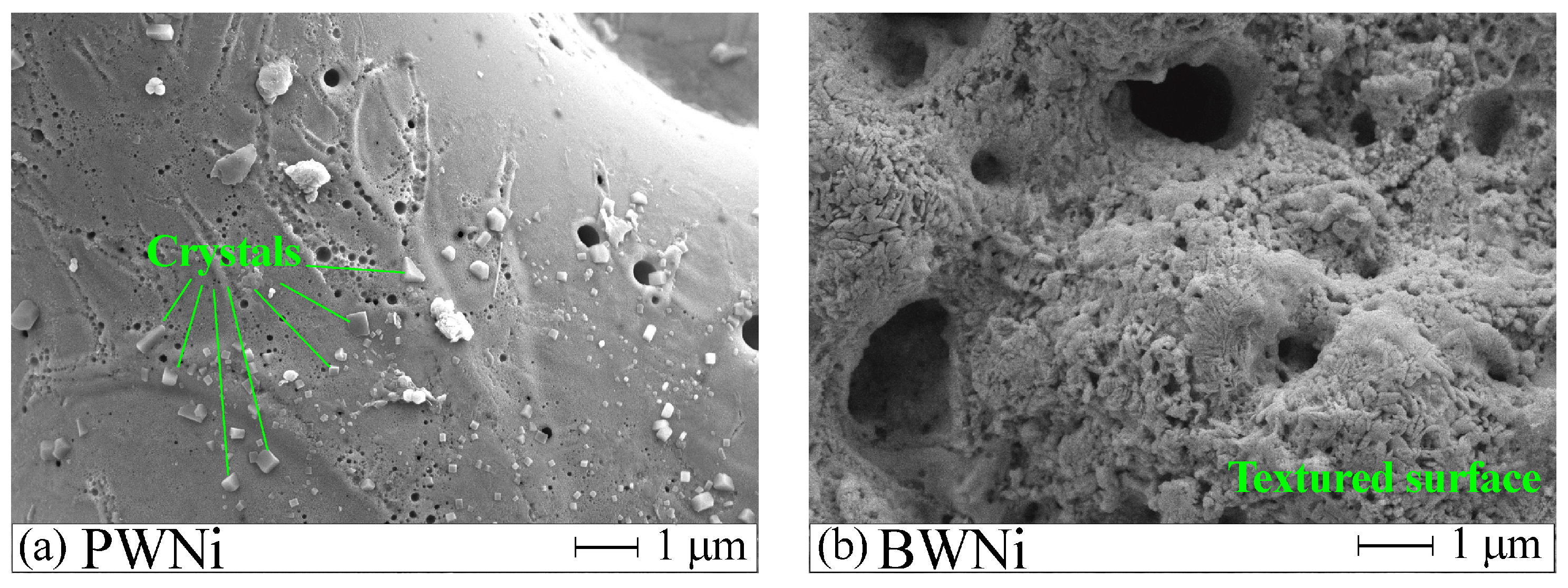
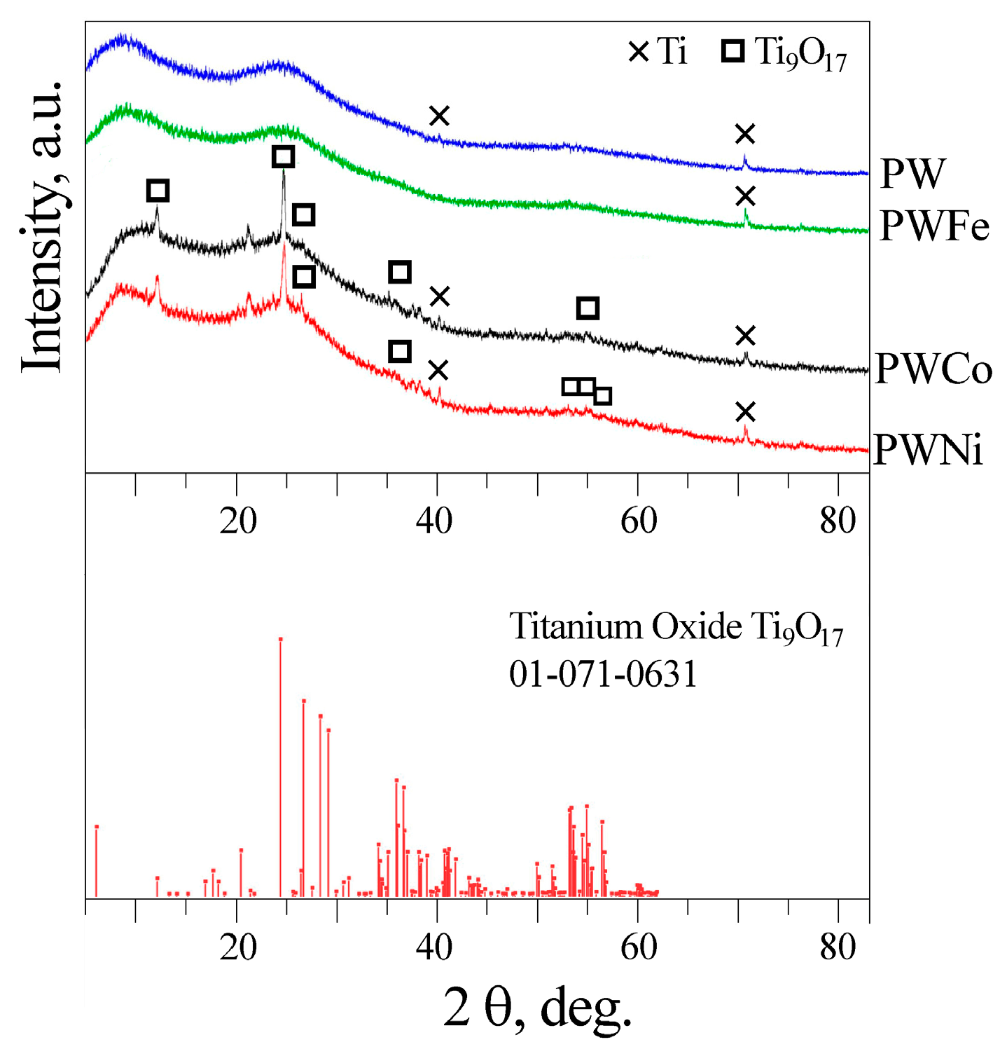
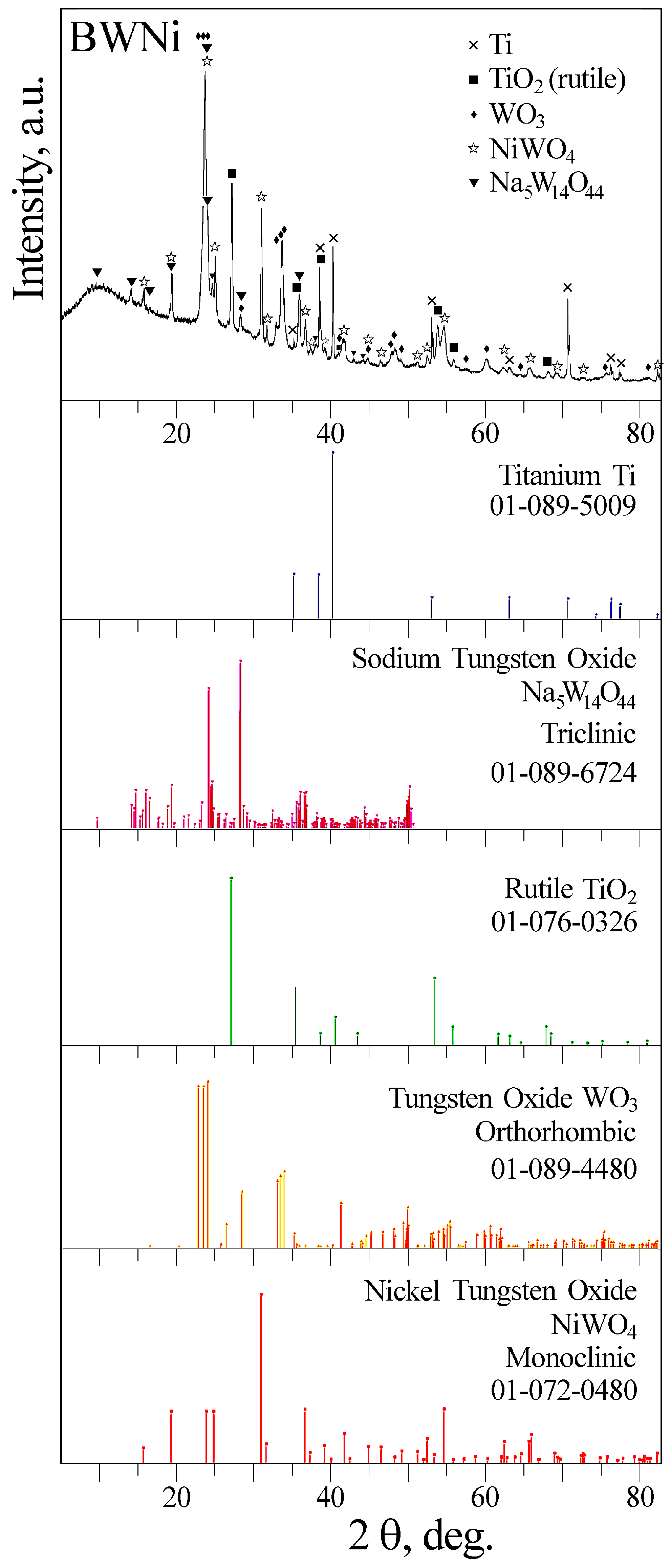
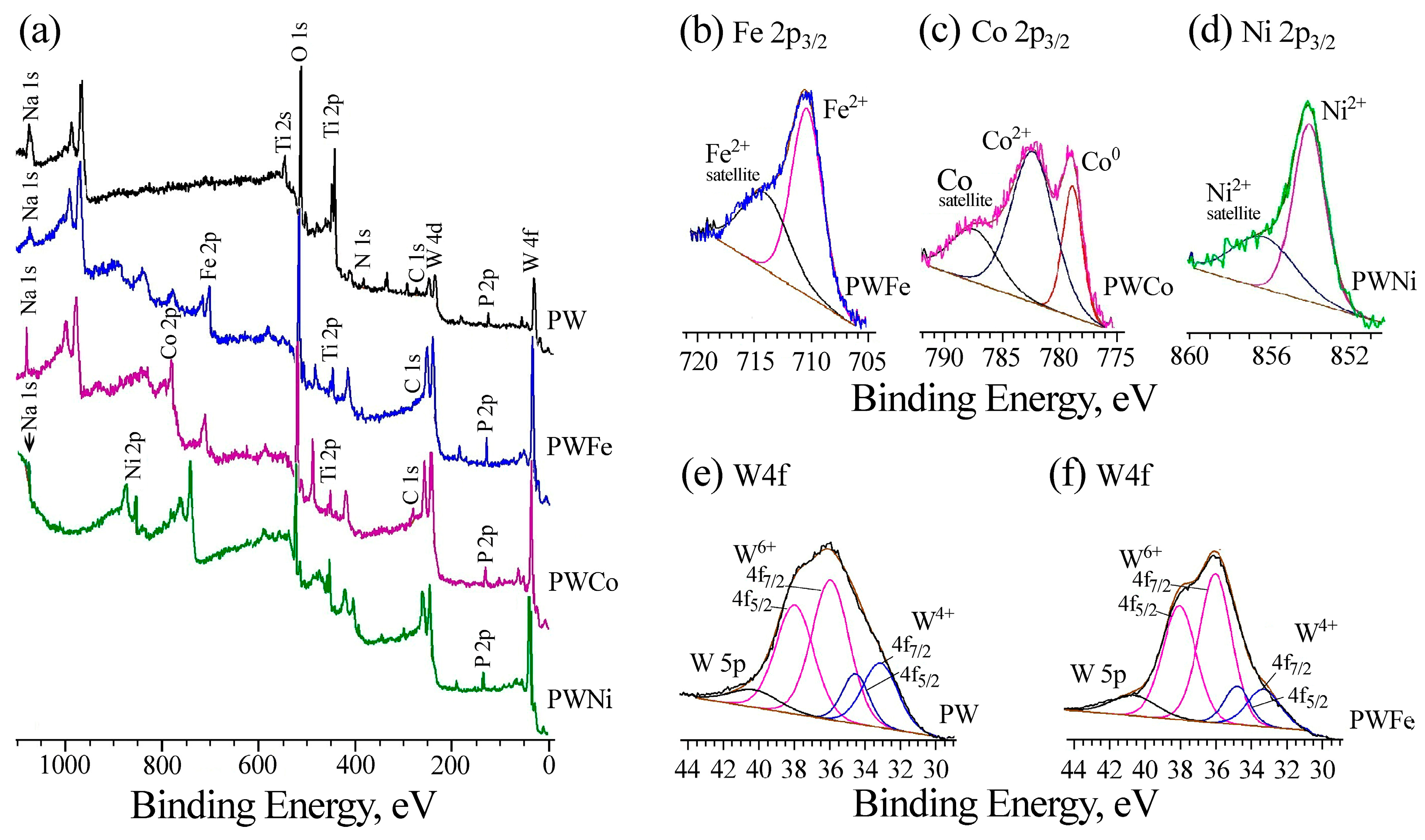
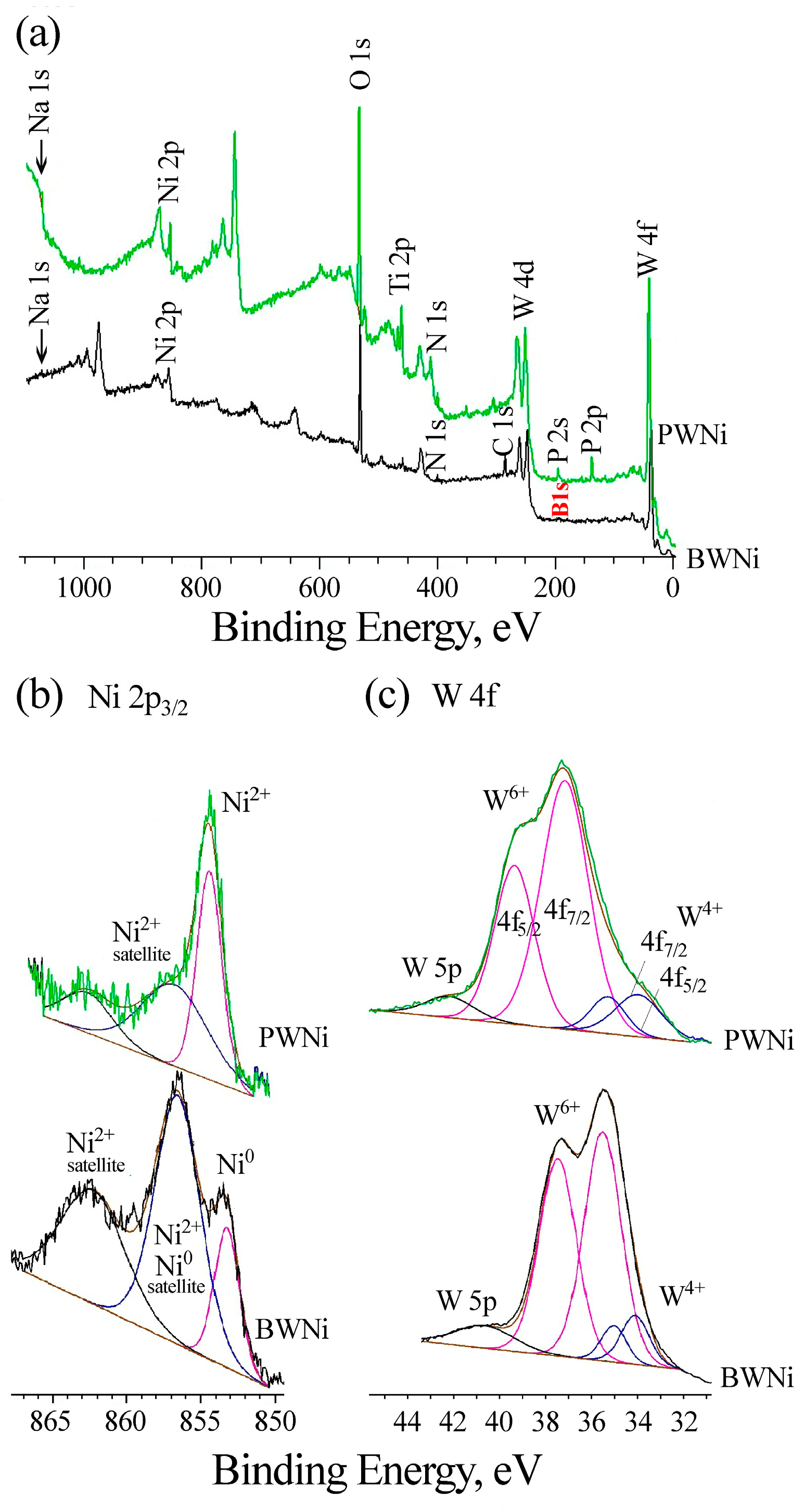
2.1. Preparation and Characterization of Catalysts

The Ti-supported catalysts were synthesized by the PEO technique. The formation curves are given in Figure S1 (Supplementary File). The thickness of the coatings formed in the PW-based electrolytes is about 30 μm. The formation voltage in the BWNi electrolyte is reduced compared to the PWNi electrolyte, which is accompanied by a twofold decrease in the coating thickness (Table 1).
The influence of the electrolyte on the surface morphology can be seen in the SEM images in Figure 1. All coatings obtained in phosphate–tungstate electrolytes have a similar surface morphology, with melted areas formed by the rapid cooling of the coating material heated by electrical discharges upon contact with the cold electrolyte, and cracks. The surface is permeated with pores of submicron (up to 1 μm) and micron sizes (1–12 μm). Large pores are obviously caused by powerful electrical discharges, while small ones are traces of gas bubbles, which corresponds to the classification of electrical discharges in Ref. [44].
Replacing the PWNi electrolyte with BWNi results in the disappearance of large pores and cavities (Figure 1g,h). Comparing the surface morphology of the PWNi and BWNi samples in high-magnification images (Figure 2), one can see the difference in the surface formations. These are regularly faceted crystals on the surface of the PWNi sample (Figure 2a) and a completely textured surface in the case of the BWNi sample (Figure 2b).
It should be noted that all the studied coatings have a two-layer structure with a dense fine-pored inner layer adjacent to titanium and a loose outer layer. Examples are shown in Figure 1a,b,h. According to EDX data, the inner layers contain more titanium, while the outer layers are enriched with electrolyte elements (Table 2).
The introduction of EDTA complexes of transition metals into the base PW electrolyte did not reduce the concentration of tungsten in the formed coatings. Comparing the elemental compositions of the PEO coatings obtained in PWNi and BWNi electrolytes, it can be noted that the latter contain less titanium, more tungsten and nickel, and boron instead of phosphorus.
The XRD patterns of the PW and PWM (M = Fe, Co, Ni) samples are shown in Figure 3. In all cases, peaks of titanium from the substrate are visible. The XRD patterns of the PWNi and PWCo samples contain peaks that can be attributed to partially reduced titanium dioxide Ti9O17. Since TiO2 is always formed at the initial stage of PEO treatment of titanium [18], it should be present in the other two samples. In addition, all XRD patterns show two amorphous halos in the regions of 2θ = 5–17° and 20–32°. At the same time, crystalline compounds of the tungsten and iron triad metals were not detected. In Ref. [45], the broad peak near 2θ = 20–35° observed in the samples processed at low current densities in an electrolyte containing 0.01 mol/L K4P2O7 and 0.02 mol/L KOH was explained by the formation of an amorphous P-containing phase. Considering the high concentrations of phosphorus in the coatings and the possibility of glass formation in the WO3-P2O5 [46] and WO3-TiO2-P2O5 [47] systems, the presence of amorphous phosphates and tungstates of iron triad metals in our samples can be assumed.
Replacing phosphate with borate in the base electrolyte (BWNi) resulted in crystallized coatings containing rutile, tungsten trioxide, nickel tungstate, and sodium tungsten bronze-like compound (Figure 4, Figures S3 and S4). The fact that borate in the BW electrolyte promotes the crystallization of tungsten compounds in PEO coatings was previously reported in Ref. [22].
The chemical composition of the subsurface layers of the samples was determined based on the XPS data (Figure 5, Table 3). Since the surface layers are heavily contaminated with carbon (18–41 at. % C, Table S1 in Supplementary Materials), the samples were bombarded with argon ions, which resulted in a decrease in the carbon concentration (to 2.5–7.2 at.% for PWM samples and to 19.4 at.% for PWNi) and etching of the surface layers of the PEO coatings to a depth of ~30 Å.
The C1s band is contributed by oxidized (Eb~288 eV), aliphatic (C=C, C-H, Eb = 285 eV) and carbide carbon (Eb~283 eV). The formation of carbide carbon in PEO coatings on titanium after etching was noted in [48]. The O1s bands are contributed by the P-O and C-O structures with binding energies in the range of 532–533 eV and the M-O state (Eb = 530.6–531.5 eV). Titanium is predominantly in the Ti4+ state. In the region of lower binding energies, a contribution from the Ti-N state is observed, which is confirmed by the presence of the N 1s peak with a binding energy in the range of 400 eV. Phosphorus is in the P5+ state, which corresponds to our assumptions about the presence of phosphates or phosphate glasses in the coatings. All coatings are characterized by a large contribution of tungsten, which is in the W6+ and W4+ states (Table 3), while only W6+ is present in the surface layers (Table S1). When iron triad metals are introduced into the coatings, the proportion of W6+ increases slightly, and the W 4f band itself becomes narrower (Figure 5e,f). The oxidation state of 3d metals is traditional for such systems. Iron and nickel are in the oxidation state +2, although Fe3+ is also present in the surface layers of the PWFe sample (Table S1). In the Co 2p spectrum after etching, both Co2+ and Co0 are observed with Eb of 782.0 and 778.5 eV, respectively.
Comparison of the XPS spectra of PWNi and BWNi samples (Figure 6) shows that when phosphate is replaced by borate in the electrolyte, B3+ is incorporated into the coating composition instead of P5+, the W4f spectrum narrows, and Ni0 appears along with Ni2+ after etching the samples. A decrease in the width of the W4f spectrum is accompanied by the crystallization of nickel tungstates in the coating composition, according to XRD data (Figure 4).
A decrease in the oxidation degree of metals during their incorporation from the electrolyte into the PEO coatings was also noted in Refs. [49,50]. The reason for the appearance of reduced (Ni0, Co0) or partially reduced metals (W4+) in the composition of anodic coatings may be the action of hydrogen released at the anode during the thermolysis of water molecules [51], thermal decomposition of M−EDTA complexes [52], and also bombardment of the surface with high-energy argon ions [53].

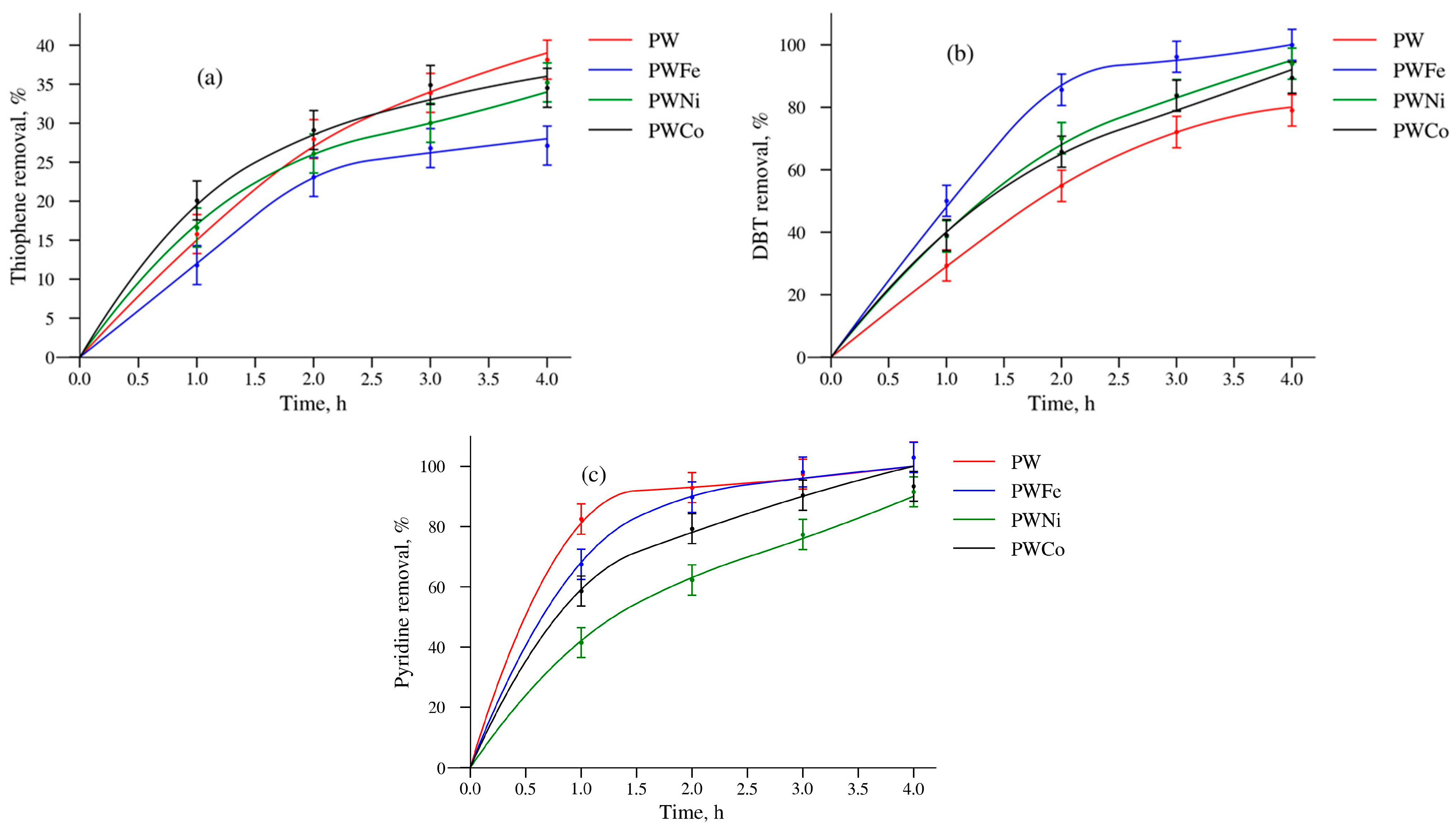
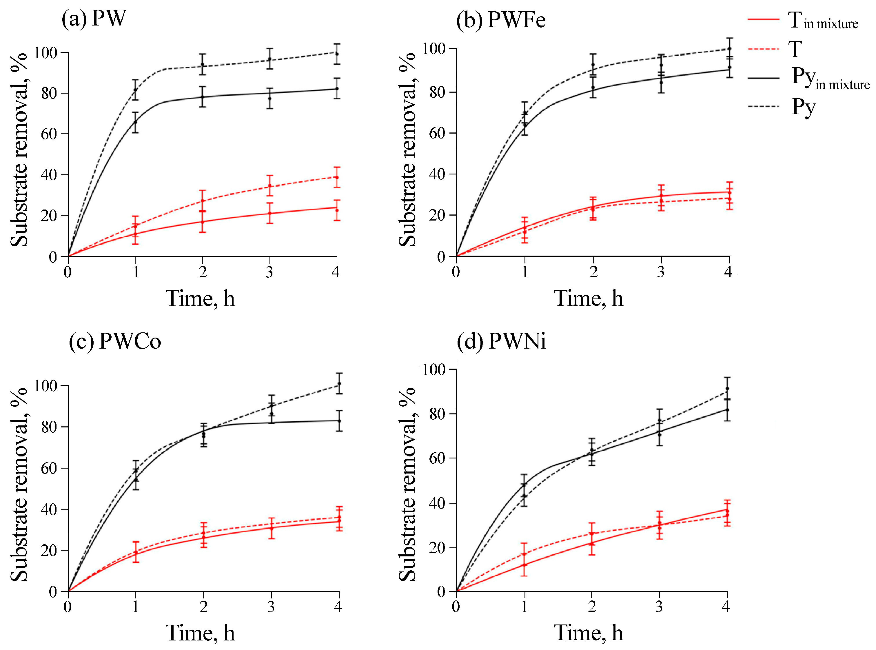
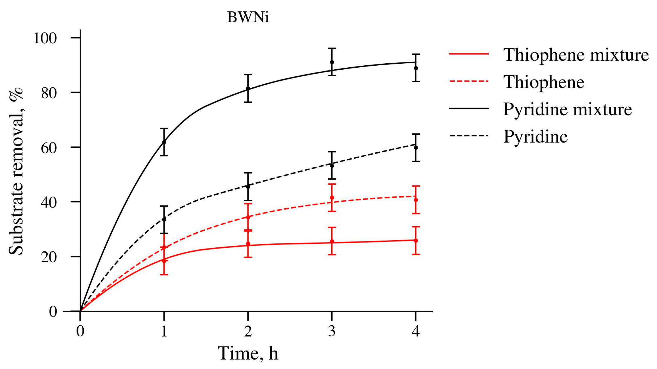
2.2. Catalytic Properties

The dosage of oxidant was marked as O/S (the molar ratio of H2O2 to sulfur). When the O/S molar ratio reached up to 4 or 8, the desulfurization rate significantly increased; this was because of the increasing production quantity of catalytic activity species [4]. However, the sulfur removal slightly decreased when the O/S molar ratio was increased to 12. The catalyst deactivation could be attributed to the occupation of catalyst surface by excessive water in the ODS process [19]. Taking the desulfurization efficiency into account, an O/S molar ratio of 4 was selected as the optimal conditions.
The conditions for the catalysis were chosen based on the analysis of our previous studies and literature data [54,55]. A temperature of 60 °C is optimal since it ensures a sufficiently high rate of the target oxidation reaction, while its increase leads to an acceleration of the side reaction of peroxide decomposition and the destruction of metal peroxo complexes responsible for catalysis [56]. According to Ref. [57], the optimal peroxide to substrate ratio ranges from 4:1 to 8:1, depending on the reactivity of the substrate and the nature of the reaction products. It is known that the oxidation of thiophene can proceed up to the formation of SO42− and CO2, with thiophene being one of the most difficult-to-oxidize heterocycles [34,58]. Therefore, in the case of our reaction involving thiophene, the smallest amount of peroxide was used in order to prevent deep oxidation and reduce the contribution of the side reaction of peroxide decomposition.
The catalytic properties of the PW and PWM samples in the oxidation of T, DBT and Py with hydrogen peroxide are presented in Figure 7. The catalytic properties of the BWNi sample will be presented later.
It is evident that the activity of the samples depends on the nature of the substrate. In the reaction with thiophene, the PWCo sample was the most active at the initial stage, but after 4 h, the PW sample showed the best results. The PWFe sample turned out to be the most stable: a high degree of thiophene removal was maintained for five cycles. Such regularities can be explained by the greater stability of the PWFe oxide layer on the surface of the titanium support leading to minimal weight loss (Table 4).
As demonstrated by the analysis of the data in Table 4, the activity of Ni- or Co-containing catalysts in the oxidation of all substrates can be associated with the leaching of the active phase components into the solution and the appearance of soluble catalytic complexes. On the other hand, in the reaction with DBT and pyridine, the PWFe catalyst was the most active both at the initial stage and at the end of the reaction, although its weight loss was minimal (Table 4). Thus, the leaching of the active substance into the solution is not a necessary condition for high activity from the PEO catalyst.
From the analysis of the data in Table 4, it follows that the stability of samples with amorphous MWO4 increases in the following series: PWNi < PWCo < PW < PWFe, with the PWNi catalyst being the least stable. At the same time, in the absence of phosphorus oxide, mixed oxide layers based on WO3 + NiWO4 were quite effective in the ODS and ODN reactions [59]. To increase the stability of the Ni-, W-containing PEO catalyst, Na3PO4 was replaced by Na2B4O7 in the electrolyte. Indeed, in this case, we obtained a BWNi sample that was active in the reactions of oxidation of T, DBT and Py and more stable compared to the PWNi sample (Table 4 and Table 5).
The oxidation of thiophene on heterogeneous catalysts can be described using the first-order kinetic equation (ln C0/C = kt) [60]. Table 5 shows the rate constants of substrate oxidation under optimal conditions for the most stable samples.
Taking into account that thiophene is converted to SO42− [34], the highest H2O2 efficiency (more than 45%) was observed for its oxidation on PW and BWNi catalysts. The BWNi sample exhibited greater oxidation activity with thiophene and dibenzothiophene with the least leaching.
All the catalysts were tested in co-oxidation reactions of thiophene and pyridine (Figure 8). As demonstrated by the analysis in Figure 8, the presence of pyridine affects the oxidation of thiophene only over the PW catalyst. Seemingly, in this case, the oxidation of pyridine occurs mainly on the surface of the composite (see Table 4), and the products of its transformation block the active centers and inhibit the oxidation of thiophene.
To confirm this assumption, the surface of the PW catalyst after the reaction with thiophene and its mixture with pyridine was analyzed by XPS. The data are presented in Table 6 and Figures S5 and S6.
The analysis in Table 6 shows that after the reaction with T, oxygen derivatives of sulfur (~0.8 at.% S as SO42−) were present on the surface of the PW catalyst. In addition, the surface contained the products of the transformation of nitrogen compounds of the catalyst: 0.3 at.% N in the form of oxidation derivatives (O-NR3) and 3.0 at.% N in the form of quaternary ammonium derivatives arising due to the interaction with sulfuric acid. After the reaction with the mixture of substrates (T + Py), the concentrations of NR4+ and oxygen derivatives of sulfur decreased to 1.5 at.% and 0.2 at.%, respectively, but the amount of oxygen derivatives of nitrogen increased to 1.8 at.%. Thus, it can be concluded that the surface was covered mainly with nitrogen derivatives, which hindered the reaction of thiophene.
On the contrary, an insignificant influence of thiophene on pyridine oxidation was observed for another leaching-resistant catalyst, PWFe, as well as for PWCo. When using the most unstable catalyst, PWNi, a complete absence of the influence of both substrates was observed: seemingly, the release of ions into the solution and the formation of homogeneous active complexes allow the oxidation reactions of thiophene and pyridine to proceed independently of each other.
Compared with the PWNi sample, the BWNi sample containing crystalline nickel and tungsten compounds was quite active in oxidation reactions and was more stable (Table 4 and Table 5). Analysis of Figure 9 confirms the earlier conclusion that, for a stable catalyst, the mutual influence of substrates in their simultaneous oxidation is very significant and is seemingly related to the blocking of active centers on the surface.
As with the PW catalyst, the decrease in thiophene conversion in the mixture on BWNi can be explained by the strong binding of pyridine or the products of its oxidation with the sample surface. The nature of such a strong acceleration of the pyridine reaction in the presence of thiophene can be related to the appearance of sulfonic acid that binds basic pyridine and exhibits activity in catalysis.
Thus, the formation of crystalline coatings containing NiWO4 and WO3 and the appearance of metallic nickel (Ni0) in the BWNi subsurface layers increased the stability of the catalyst (Table 4) and led to a selectivity for pyridine oxidation in the presence of thiophene (Figure 9).

3. Materials and Methods

3.1. Pre-Treatment of Titanium Samples and Preparation of Catalysts

The supports for applying catalytic coatings were made of sheet titanium grade VT1–0 (wt. %: 0.7 Al, 0.25 Fe, 0.10 Si, 0.07 C, 0.04 N, 0.2 O, 0.01 H; other impurities—0.30 and Ti—the rest). The dimensions of the plates were 2.0 × 2.0 × 0.05 mm. The titanium plates were subjected to mechanical grinding, chemical polishing in a mixture of concentrated acids (HF:HNO3 = 1:3 in volume ratio) at 60−80 °C, washing with distilled water, and drying in air at 70 °C.
To apply catalytically active compositions to the surface of the titanium samples, anodic treatment in the spark and microarc electric discharge mode was used. The PEO treatment was carried out in an electrochemical cell—a 1 L polypropylene beaker with the electrolyte, into which the titanium sample being treated and a counter electrode were placed. The sample was connected to the positive pole of the current source—a PC-controlled TER4–100/460N–2–2UKhL4 thyristor unit (Russia) operating in the unipolar mode. A hollow nickel coil served as a counter electrode. Tap water was passed through this coil to cool the electrolyte, which was magnetically stirred so that the temperature did not exceed 35 °C during the PEO process. After PEO treatment, the samples were washed with distilled water and dried in air.
The parameters of PEO treatment and electrolyte formulas are given in Table 1. The electrolytes were prepared using distilled water and commercially available reagent-grade chemicals: Na3PO4·12H2O, Na2B4O7·10H2O, Na2WO4·2H2O, (NH4)2Fe(SO4)2·6H2O, Co(CH3COO)2·4H2O, Ni(CH3COO)2·4H2O, and C10H14N2Na2·2H2O. A solution of 0.05 M Na3PO4 + 0.1 M Na2WO4 (in a special case, 0.05 M Na2B4O7 + 0.1 M Na2WO4) was used as the base electrolyte, into which EDTA complexes of iron triad metals were introduced. Acetates of cobalt and nickel were used as sources of Co(II) and Ni(II), and Mohr’s salt served as a source of Fe(II).

3.2. Characterization of Catalyst Surfaces

The Ti-supported catalysts were characterized by X-ray diffraction (XRD), energy-dispersive X-ray (EDX) analysis, scanning electron microscopy (SEM), and X-ray photoelectron spectroscopy (XPS).
X-ray diffraction patterns of PEO-coated samples were recorded on a STADI P diffractometer (STOE & Cie GmbH, Darmstadt, Germany) in the range of 2θ angles from 5 to 80° with a step of 0.5° (Ni filter). Phase identification was performed based on the PDF-2 database.
The morphology and elemental composition of sample surfaces were investigated using high-resolution scanning electron microscopy (SEM) and energy-dispersive X-ray (EDX) microanalysis. Experiments were carried out using a ZEISS ULTRA 55+ scanning electron microscope (Carl Zeiss AG, Oberkochen, Germany) equipped with an Oxford X-MAX EDX detector (Oxford Instruments PLC, Abingdon, Oxfordshire, UK). Images were acquired at an accelerating voltage of 5 kV, and the edges were observed at a 45-degree angle. Elemental analysis was performed at an accelerating voltage of 20 kV. The scanning beam penetration depth was approximately 1 µm, and the sizes of the analyzed areas for determining the overall composition of the coatings were at least 50 × 50 µm. Preliminary intensity calibration was performed using a cobalt standard.
The X-ray photoelectron spectra were recorded on a Specs ultra-high vacuum photoelectron spectrometer (SPECS GmbH—Surface Analysis and Computer Technology, Berlin, Germany) with a hemispherical electrostatic analyzer (radius of curvature—150 mm) and AlKα radiation source (source energy—1456.6 eV) at pressures in the analysis chamber of 10−6–10−7 Pa. Survey spectra were recorded in the range of 1100−0 eV. The spectra were processed using the CasaXPS Version 2.3.12 program. The calibration of the electron binding energy scale was performed using the internal standard technique for which C1s level (285.0 eV) was chosen. The spread function of the spectrometer in the mode of characteristic atomic level registration, which was determined by the shape of the Ag 3d5/2 band, had a half-width of 1.2 eV. To remove carbon contamination, each sample was bombarded with high-energy Ar+ ions, etching the surface to a depth of 30 Å. The composition of the subsurface layers was then analyzed.
The thickness of the formed PEO coatings was measured 10–12 times on both sides of each sample using a VT-201 eddy current thickness gauge (Control, Measurement, Diagnostics LLC, Khimki, Russia). The obtained data were averaged.

3.3. Catalytic Testing and Reaction Product Analysis

For catalytic testing, the PEO-coated titanium samples were cut into 0.1 g pieces. These plates and 5 mL of model solution (1 wt. % thiophene, dibenzothiophene, or pyridine in isooctane) were placed into a jacketed glass reactor. To carry out the reaction with T and Py, the corresponding solutions (2.5 mL + 2.5 mL) were simultaneously poured into the reactor. The reaction mixture was magnetically stirred then heated to 60 °C, after which 0.2 mL of 30% H2O2 solutions was added. After the completion of the reaction, the liquid phase was decanted, and the catalyst was washed with isooctane. Next, a new portion of the reagents was placed in the reactor, and the tests were carried out in the same way for 5 cycles.
Samples of the organic phase were taken from the reaction mixture every hour and analyzed by gas–liquid chromatography on a Crystal 4000 instrument (Meta-Chrome LLC, Yoshkar-Ola, Russia, the measurement error was ±3.0%) equipped with a 30 m long Zebron ZB-1 capillary column (Phenomenex Inc., Torrance, CA, USA, 100% dimethylpolysiloxane as the liquid phase) and a flame ionization detector (FID) using an internal standard (n-nonane or n-dodecane).

4. Conclusions

1. Ti-supported catalysts with amorphous tungstates of iron triad metals were successfully synthesized by the PEO technique in phosphate–tungstate electrolytes with chelate complexes of iron, cobalt or nickel. The obtained catalysts showed activity in both separate and combined oxidation of S- and N-containing organic substrates (thiophene, dibenzothiophene, pyridine).
2. Replacing the phosphate–tungstate electrolyte with a borate–tungstate electrolyte resulted in the production of crystalline PEO coatings containing NiWO4 and WO3, the appearance of metallic nickel (Ni0) in the subsurface layers, an increase in the stability of the catalyst oxide layer, and the appearance of selectivity towards pyridine in the simultaneous oxidation of thiophene and pyridine. The resulting BWNi sample exhibited greater oxidation activity with thiophene (H2O2 efficiency more than 45%) and dibenzothiophene with the least leaching.

Supplementary Materials

The following supporting information can be downloaded at: https://www.mdpi.com/article/10.3390/molecules30091998/s1, Figure S1: Voltage–time responses during PEO treatment of titanium samples in PW, PWM (M = Fe, Co, Ni) and BWNi electrolytes. The formation curves were obtained by averaging 3–5 scans in each electrolyte. Figure S2: An example of determining the elemental composition of BWNi sample on the outer and inner surface areas. Spectrum 1 refers to the outer layer, while spectra 2 and 3 characterize the delamination areas (the surface of the inner layer). Figure S3: XRD pattern of PWNi sample. Figure S4: XRD pattern of BWNi sample. Figure S5: Survey and regional S2p XPS spectra of sample PW after the thiophene oxidation reaction. Figure S6: Survey and regional N1s XPS spectra of sample PW after the oxidation of the thiophene—pyridine mixture. Table S1: Binding energies Eb and element concentrations C for surface and subsurface layers of PEO composites.

Author Contributions

I.G.T.: Investigation, conceptualization, validation, writing—original draft, writing—review and editing. V.M.Z.: investigation, visualization. I.V.L.: investigation, validation, project administration, conceptualization, writing—original draft, writing—review and editing. M.S.V.: investigation, formal analysis, writing—original draft, writing—review and editing. V.V.T.: methodology, investigation. V.V.K.: investigation, validation, writing—original draft. D.H.S.: investigation, visualization. All authors have read and agreed to the published version of the manuscript.

Funding

The catalyst synthesis was performed within the framework of the Institute of Chemistry FEB RAS State Order (project no. FWFN (0205)-2025-0001). A comparative analysis of the catalytic properties of samples in oxidative reactions were carried out within the framework of the State Assignment of Lomonosov Moscow State University (project No. AAAA-A21-121011590090-7).

Informed Consent Statement

Not applicable.

Data Availability Statement

Data will be made available on request.

Acknowledgments

The study of the morphology and elemental composition of the samples by SEM and EDX methods was carried out using the equipment of the Center for Collective Use of the Far Eastern Federal University No. 200556 (Vladivostok). The phase and chemical composition and catalysts were determined using the equipment of the Far Eastern Center for Structural Research’s Center for Collective Use, created on the basis of the Institute of Chemistry of FEB RAS.

Conflicts of Interest

The authors declare no conflicts of interest.

Abbreviations

The following abbreviations are used in this manuscript:
PEOplasma electrolytic oxidation
ODSoxidative desulfurization
ODNoxidative denitrogenation
EDXenergy-dispersive X-ray spectroscopy
XPSX-ray photoelectron spectroscopy
XRDX-ray diffraction analysis

References

  1. Rudnev, V.S. Multiphase anodic layers and prospects of their application. Prot. Met. 2008, 44, 263–272. [Google Scholar] [CrossRef]
  2. Famiyeh, L.; Huang, X. Plasma electrolytic oxidation coatings on aluminum alloys: Microstructures, properties, and applications. Mod. Concept. Mater. Sci. 2019, 2, 000526. [Google Scholar] [CrossRef]
  3. Aliofkhazraei, M.; Macdonald, D.D.; Matykina, E.; Parfenov, E.V.; Egorkin, V.S.; Curran, J.A.; Troughton, S.C.; Sinebryukhov, S.L.; Gnedenkov, S.V.; Lampke, T.; et al. Review of plasma electrolytic oxidation of titanium substrates: Mechanism, properties, applications, and limitations. Appl. Surf. Sci. Adv. 2021, 5, 100121. [Google Scholar] [CrossRef]
  4. Fattah-alhosseini, A.; Chaharmahali, R.; Dikici, B.; Kaseem, M. A comprehensive review of plasma electrolytic oxidation (PEO) of tantalum (Ta): Mechanisms, properties, and applications. Int. J. Refract. Met. Hard Mater. 2025, 128, 107059. [Google Scholar] [CrossRef]
  5. Darband, G.B.; Aliofkhazraei, M.; Hamghalam, P.; Valizade, N. Plasma electrolytic oxidation of magnesium and its alloys: Mechanism, properties and applications. J. Magnes. Alloys 2017, 5, 74–132. [Google Scholar] [CrossRef]
  6. Hou, F.; Gorthy, R.; Mardon, I.; Tang, D.; Goode, C. Protecting light metal alloys using a sustainable plasma electrolytic oxidation process. ACS Omega 2022, 7, 8570–8580. [Google Scholar] [CrossRef] [PubMed]
  7. Pourshadloo, M.; Rezaei, H.A.; Saeidnia, M.; Alkokab, H.; Bathaei, M.S. Effect of g-family incorporation on corrosion behavior of PEO-treated titanium alloys: A review. Surf. Innov. 2023, 11, 5–14. [Google Scholar] [CrossRef]
  8. Ming, X.; Wu, Y.; Zhang, Z.; Li, Y. Micro-arc oxidation in titanium and its alloys: Development and potential of implants. Coatings 2023, 13, 2064. [Google Scholar] [CrossRef]
  9. Karbasi, M.; Nikoomanzari, E.; Hosseini, R.; Bahramian, H.; Chaharmahali, R.; Giannakis, S.; Kaseem, M.; Fattah-alhosseini, A. A review on plasma electrolytic oxidation coatings for organic pollutant degradation: How to prepare them and what to expect of them? J. Environ. Chem. Eng. 2023, 11, 110027. [Google Scholar] [CrossRef]
  10. Ogur, E.; Alves, A.C.; Toptan, F. Advancing titanium-based surfaces via micro-arc oxidation with solid substance incorporation: A systematic review. Mater. Today Commun. 2024, 41, 110343. [Google Scholar] [CrossRef]
  11. Samadi, P.; Witonska, I.A. Plasma electrolytic oxidation layers as alternative supports for metallic catalysts used in oxidation reaction for environmental application. Catal. Commun. 2023, 181, 106722. [Google Scholar] [CrossRef]
  12. Borisov, V.A.; Sigaeva, S.S.; Anoshkina, E.A.; Ivanov, A.L.; Litvinov, P.V.; Vedruchenko, V.R.; Temerev, V.L.; Arbuzov, A.B.; Kuznetsov, A.A.; Mukhin, V.A.; et al. Plasma electrolytic oxide coatings on silumin for oxidation CO. AIP Conf. Proc. 2017, 1876, 020001. [Google Scholar] [CrossRef]
  13. Karakurkchi, A.; Sakhnenko, M.; Ved, M.; Gorokhyvskiy, A. Nanostructured PEO coatings on silumin as environmental catalysts. Mater. Today Proc. 2022, 50, 502–506. [Google Scholar] [CrossRef]
  14. Quintero, D.; Galvis, O.; Calderón, J.A.; Castaño, J.G.; Echeverría, F. Effect of electrochemical parameters on the formation of anodic films on commercially pure titanium by plasma electrolytic oxidation. Surf. Coat. Technol. 2014, 258, 1223–1231. [Google Scholar] [CrossRef]
  15. Adelinia, A.; Yerokhin, A.; Matthews, D.T.A.; de Rooij, M.B.; Zanjani, J.S.M. Pore formation and pore inter-connectivity in plasma electrolytic oxidation coatings on aluminium alloy. Surf. Coat. Technol. 2025, 496, 131597. [Google Scholar] [CrossRef]
  16. Sharifi, H.; Aliofkhazraei, M.; Darband, G.B.; Shrestha, S. A review on adhesion strength of PEO coatings by scratch test method. Surf. Rev. Lett. 2018, 25, 1830004. [Google Scholar] [CrossRef]
  17. Patcas, F.; Krysmann, W. Efficient catalysts with controlled porous structure obtained by anodic oxidation under spark-discharge. Appl. Catal. A Gen. 2007, 316, 240–249. [Google Scholar] [CrossRef]
  18. Zhang, X.; Cai, G.; Lv, Y.; Wu, Y.; Dong, Z. Growth mechanism of titania on titanium substrate during the early stage of plasma electrolytic oxidation. Surf. Coat. Technol. 2020, 400, 126202. [Google Scholar] [CrossRef]
  19. Xu, J.; Holthaus, P.; Yang, N.; Jiang, S.; Heupel, A.; Schönherr, H.; Yang, B.; Krumm, W.; Jiang, X. Catalytic tar removal using TiO2/NiWO4-Ni5TiO7 films. Appl. Catal. B Environ. 2019, 249, 155–162. [Google Scholar] [CrossRef]
  20. Wu, Z.; Wang, J.; Chen, C.; Xia, Q.; Yao, Z. Enhanced Fenton-like degradation of phenol by sulfur modified α-Fe2O3/Fe3O4/R-TiO2 composite coating on Ti alloy prepared by plasma electrolytic oxidation. Mater. Res. Express 2019, 6, 095532. [Google Scholar] [CrossRef]
  21. Vasilyeva, M.S.; Lukiyanchuk, I.V.; Sergeev, A.A.; Sergeeva, K.A.; Ustinov, A.Y.; Tkachev, V.V.; Arefieva, O.D. Plasma electrolytic synthesis and characterization of oxide coatings with MWO4 (M =Co, Ni, Cu) as photo-Fenton heterogeneous catalysts. Surf. Coat. Technol. 2021, 424, 127640. [Google Scholar] [CrossRef]
  22. Budnikova, Y.B.; Vasilyeva, M.S.; Lukiyanchuk, I.V.; Egorkin, V.S.; Tkachev, V.V.; Korochentsev, V.V.; Shlyk, D.H.; Arefieva, O.D.; Marchenko, A.V.; Myagchilov, A.V. Plasma electrolytic preparation of film CoWO4/WO3 p-n heterostructures and their photocatalytic and electrochemical properties. J. Photochem. Photobiol. A Chem. 2025, 467, 116414. [Google Scholar] [CrossRef]
  23. Lukiyanchuk, I.V.; Tarkhanova, I.G.; Vasilyeva, M.S.; Yarovaya, T.P.; Ustinov, A.Y.; Vyaliy, I.E.; Kuryavyi, V.G. Plasma electrolytic formation of TiO2-VOx-MoOy-P2O5 coatings on titanium and their application as catalysts for the oxidation of S- and N-containing substances. Mater. Chem. Phys. 2024, 311, 128520. [Google Scholar] [CrossRef]
  24. Said, S.; Mikhail, S.; Riad, M. Recent trends for clean fuel using environmental protecting oxidative desulfurization process. Clean. Chem. Eng. 2025, 11, 100140. [Google Scholar] [CrossRef]
  25. Shafiq, I.; Shafique, S.; Akhter, P.; Ishaq, M.; Yang, W.; Hussain, M. Recent breakthroughs in deep aerobic oxidative desulfurization of petroleum refinery products. J. Clean. Prod. 2021, 294, 125731. [Google Scholar] [CrossRef]
  26. Haruna, A.; Merican, Z.M.A.; Musa, S.G. Recent advances in catalytic oxidative desulfurization of fuel oil—A review. J. Ind. Eng. Chem. 2022, 112, 20–36. [Google Scholar] [CrossRef]
  27. Taghizadeh, M.; Mehrvarz, E.; Taghipour, A. Polyoxometalate as an effective catalyst for the oxidative desulfurization of liquid fuels: A critical review. Rev. Chem. Eng. 2020, 36, 831–858. [Google Scholar] [CrossRef]
  28. Saladino, R.; Botta, G.; Crucianelli, M. Advances in Nanostrostructured Transition Metal Catalysis Applied to Oxidative Desulfurization. In Applying Nanotechnology to the Desulfurization Process in Petroleum Engineering; Tawfik, A.S., Ed.; IGI Global: Hershey, PA, USA, 2016; pp. 180–215. [Google Scholar]
  29. Mohammed, A.E.; Mohammed, W.T.; Gheni, S.A. Scale-up of oxidative desulfurization for sour diesel fuel: Modeling, simulation, and reactor design using Fe/AC catalyst. Case Stud. Chem. Environ. Eng. 2025, 11, 101024. [Google Scholar] [CrossRef]
  30. Saeed, M.; Munir, M.; Intisar, A.; Waseem, A. Facile synthesis of a novel Ni-WO3@g-C3N4 nanocomposite for efficient oxidative desulfurization of both model and real fuel. ACS Omega 2022, 7, 15809–15820. [Google Scholar] [CrossRef] [PubMed]
  31. Ma, X.L.; Sprague, M.; Song, C.S. Deep desulfurization of gasoline by selective adsorption over nickel-based adsorbent for fuel cell applications. Ind. Eng. Chem. Res. 2005, 44, 5768–5775. [Google Scholar] [CrossRef]
  32. Rezvani, M.A.; Hemmatzadeh, A.; Oroumi, G.; Miri, O.F. Enhanced catalytic activity of PMo11V/NiO/PAN nanosphere composite for real fuel oxidation desulfurization: Synthesis and characterization. Mater. Chem. Phys. 2024, 311, 128504. [Google Scholar] [CrossRef]
  33. Rezvani, M.; Bakhtiyari, A.; Rahmani, P. Synthesis and characterization of new nanocomposite PW11Mn@CuO@PAN as an efficient nanocatalyst for deep oxidative desulfurization of real/model fuel. Mater. Sci. Eng. B 2024, 303, 117314. [Google Scholar] [CrossRef]
  34. Rudnev, V.S.; Lukiyanchuk, I.V.; Vasilyeva, M.S.; Morozova, V.P.; Zelikman, V.M.; Tarkhanova, I.G. W-containing oxide layers obtained on aluminum and titanium by PEO as catalysts in thiophene oxidation. Appl. Surf. Sci. 2017, 422, 1007–1014. [Google Scholar] [CrossRef]
  35. Faria, R.G.; Silva, D.; Mirante, F.; Gago, S.; Cunha-Silva, L.; Balula, S.S. Advanced technologies conciliating desulfurization and denitrogenation to prepare clean fuels. Catalysts 2024, 14, 137. [Google Scholar] [CrossRef]
  36. Tochtermann, J.; Tietze, F.; Huber, M.; Korth, W.; Albert, J.; Jess, A. Extraction-coupled oxidative desulfurization (ECODS) and denitrogenation (ECODN) of real fuels under mild conditions using a polyoxometalate catalyst and molecular oxygen. Energy Fuels 2025, 39, 781–797. [Google Scholar] [CrossRef]
  37. Silva, D.F.; Viana, A.M.; Mirante, F.; de Castro, B.; Cunha-Silva, L.; Balula, S.S. Removing simultaneously sulfur and nitrogen from fuel under a sustainable oxidative catalytic system. Sustain. Chem. 2021, 2, 382–391. [Google Scholar] [CrossRef]
  38. Palomeque-Santiago, J.F.; López-Medina, R.; Oviedo-Roa, R.; Navarrete-Bolaños, J.; Mora-Vallejo, R.; Montoya-de la Fuente, J.A.; Martínez-Magadán, J.M. Deep oxidative desulfurization with simultaneous oxidative denitrogenation of diesel fuel and straight run gas oil. Appl. Catal. B Environ. 2018, 236, 326–337. [Google Scholar] [CrossRef]
  39. Prado, G.H.C.; Rao, Y.; de Klerk, A. Nitrogen removal from oil: A review. Energy Fuels 2017, 31, 14–36. [Google Scholar] [CrossRef]
  40. Kumari, S.; Sengupta, S. Non-hydrogen processes for simultaneous desulfurization and denitrogenation of light petroleum fuels—An elaborative review. Environ. Sci. Pollut. Res. 2021, 28, 61873–61907. [Google Scholar] [CrossRef]
  41. Lokeshkumar, E.; Premchand, C.; Manojkumar, P.; Shishir, R.; Krishna, L.R.; Prashanth, K.G.; Rameshbabu, N. Effect of electrolyte composition on the surface characteristics of plasma electrolytic oxidation coatings over Ti–40Nb alloy. Surf. Coat. Technol. 2023, 465, 129591. [Google Scholar] [CrossRef]
  42. Li, Y.; Wang, W.; Liu, H.; Lei, J.; Zhang, J.; Zhou, H.; Qi, M. Formation and in vitro/in vivo performance of “cortex-like” micro/nano-structured TiO2 coatings on titanium by micro-arc oxidation. Mater. Sci. Eng. C 2018, 87, 90–103. [Google Scholar] [CrossRef] [PubMed]
  43. Wang, W.; Zheng, X.; Yu, F.; Li, Y.; Xue, X.; Qi, M.; Li, Y. Formation and cytocompatibility of a hierarchical porous coating on Ti-20Zr-10Nb-4Ta alloy by micro-arc oxidation. Surf. Coat. Technol. 2020, 404, 126471. [Google Scholar] [CrossRef]
  44. Hussein, R.O.; Nie, X.; Northwood, D.O.; Yerokhin, A.; Matthews, A. Spectroscopic study of electrolytic plasma and discharging behaviour during the plasma electrolytic oxidation (PEO) process. J. Phys. D Appl. Phys. 2010, 43, 105203. [Google Scholar] [CrossRef]
  45. Mortazavi, G.; Jiang, J.; Meletis, E.I. Investigation of the plasma electrolytic oxidation mechanism of titanium. Appl. Surf. Sci. 2019, 488, 370–382. [Google Scholar] [CrossRef]
  46. Pershina, S.V. Conductivity studies of glasses in the system WO3–P2O5. Russ. J. Appl. Chem. 2019, 92, 482–489. [Google Scholar] [CrossRef]
  47. Moore, L.; Dutta, I.; Wheaton, B.; Stapleton, E.; Parysek, R.; Aitken, B. A new identification of the conducting phase in tungsten-titanium-phosphate glass-ceramics. J. Am. Ceram. Soc. 2020, 103, 3552–3561. [Google Scholar] [CrossRef]
  48. Vovna, V.I.; Gnedenkov, S.V.; Gordienko, P.S.; Kuznetsov, M.V.; Sinebryukhov, S.L.; Cherednichenko, A.I.; Khrisanfova, O.A. Surface layers produced on titanium by the microarc oxidation: An X-ray diffractometry study. Russ. J. Electrochem. 1998, 34, 1090–1093. [Google Scholar]
  49. Tu, W.; Cheng, Y.; Wang, X.; Zhan, T.; Han, J.; Cheng, Y. Plasma electrolytic oxidation of AZ31 magnesium alloy in aluminate-tungstate electrolytes and the coating formation mechanism. J. Alloys Compd. 2017, 725, 199–216. [Google Scholar] [CrossRef]
  50. Zhu, Z.; Tu, W.; Cheng, Y.; Cheng, Y. The formation of metallic W and amorphous phase in the plasma electrolytic oxidation coatings on an Al alloy from tungstate-containing electrolyte. Surf. Coat. Technol. 2019, 361, 176–187. [Google Scholar] [CrossRef]
  51. Snizhko, L.O. The nature of anodic gas at plasma electrolytic oxidation. Prot. Met. Phys. Chem. Surf. 2014, 50, 705–708. [Google Scholar] [CrossRef]
  52. Motekaitis, R.J.; Cox III, X.B.; Taylor, P.; Martell, A.E.; Miles, B.; Tvedt, T.J., Jr. Thermal degradation of EDTA chelates in aqueous solution. Can. J. Chem. 1982, 60, 1207–1213. [Google Scholar] [CrossRef]
  53. Biesinger, M.C.; Payne, B.P.; Grosvenor, A.P.; Lau, L.W.M.; Gerson, A.R.; Smart, R.S.C. Resolving surface chemical states in XPS analysis of first row transition metals, oxides and hydroxides: Cr, Mn, Fe, Co and Ni. Appl. Surf. Sci. 2011, 257, 2717–2730. [Google Scholar] [CrossRef]
  54. Akopyan, A.; Eseva, E.; Polikarpova, P.; Kedalo, A.; Vutolkina, A.; Glotov, A. Deep oxidative desulfurization of fuels in the presence of brönsted acidic polyoxometalate-based ionic liquids. Molecules 2020, 25, 536. [Google Scholar] [CrossRef]
  55. Polikarpova, P.; Akopyan, A.; Shigapova, A.; Glotov, A.; Anisimov, A.; Karakhanov, E. Oxidative desulfurization of fuels using heterogeneous catalysts based on MCM-41. Energy Fuels 2018, 32, 10898–10903. [Google Scholar] [CrossRef]
  56. Gao, H.; Wu, X.; Sun, D.; Niu, G.; Guan, J.; Meng, X.; Liu, C.; Xia, W.; Song, X. Preparation of core–shell PW12@TiO2 microspheres and oxidative desulfurization performance. Dalton Trans. 2019, 48, 5749–5755. [Google Scholar] [CrossRef] [PubMed]
  57. Yue, D.; Jiaheng, L.; Lina, Z.; Ran, G.Z.; Xiaodi, D.; Junsheng, L. Highly efficient deep desulfurization of fuels by meso/macroporous H3PW12O40/TiO2 at room temperature. Mater. Res. Bull. 2018, 105, 210–219. [Google Scholar] [CrossRef]
  58. Zhang, B.Y.; Jiang, Z.X.; Li, J.; Zhang, Y.N.; Lin, F.; Liu, Y.; Li, C. Catalytic oxidation of thiophene and its derivatives via dual activation for ultra-deep desulfurization of fuels. J. Catal. 2012, 287, 5–12. [Google Scholar] [CrossRef]
  59. Lukiyanchuk, I.V.; Vasilyeva, M.S.; Ustinov, A.Y.; Bryzhin, A.A.; Tarkhanova, I.G. Ti/TiO2/NiWO4 +WO3 composites for oxidative desulfurization and denitrogenation. Surf. Coat. Technol. 2022, 434, 128200. [Google Scholar] [CrossRef]
  60. Saha, B.; Sengupta, S. Influence of different hydrocarbon components in fuel on the oxidative desulfurisation of thiophene: Deactivation of catalyst. Fuel 2015, 150, 679–686. [Google Scholar] [CrossRef]
Figure 1. SEM images of the surface of PEO coatings: view at 45° (a,b,h) and top view (cg).
Molecules 30 01998 g001
Figure 2. Crystals on the surface of the PWNi sample (a) and the textured surface of the BWNi sample (b).
Molecules 30 01998 g002
Figure 3. XRD patterns of PEO-coated samples PW and PWM, where M = Fe, Co, Ni.
Molecules 30 01998 g003
Figure 4. XRD pattern of BWNi sample.
Molecules 30 01998 g004
Figure 5. Survey (a) XPS spectra and regional spectra of Fe 2p3/2 (b), Co 2p3/2 (c), Ni 2p3/2 (d), and W 4f (e,f) electrons for subsurface layers of PW (a,e), PWFe (a,b,f), PWCo (a,c), and PWNi (a,d) samples.
Molecules 30 01998 g005
Figure 6. Comparison of XPS spectra of PWNi and BWNi samples: (a) survey spectra, (b) Ni 2p3/2 spectra, (c) W4f spectra.
Molecules 30 01998 g006
Figure 7. Removal of thiophene (a), DBT (b) and pyridine (c) on PW, PWFe, PWNi and PWCo catalysts in oxidation reactions.
Molecules 30 01998 g007
Figure 8. Separate and simultaneous oxidation of thiophene and pyridine oxidation by hydrogen peroxide on (a) PW, (b) PWFe, (c) PWCo and (d) PWNi catalysts.
Molecules 30 01998 g008
Figure 9. Separate and simultaneous oxidation of thiophene and pyridine by hydrogen peroxide on BWNi catalyst.
Molecules 30 01998 g009
Table 1. Sample and electrolyte designations and coating thicknesses, electrolyte formulas, and electric modes.
LabelBase SolutionAdditivesi [A/cm2]t [min]Umax [V]Uf [V]h [μm]
PW0.05 M Na3PO4 +
0.1 M Na2WO4
No0.1 10106 ± 294 ± 229 ± 3
PWFe0.05 M Na3PO4 +
0.1 M Na2WO4
0.05 M Na2H2EDTA + 0.05 M Fe(NH4)2(SO4)20.05 1098 ± 192 ± 236 ± 3
PWCo0.05 M Na3PO4 +
0.1 M Na2WO4
0.05 M Na2H2EDTA + 0.05 M Co(CH3COO)20.1 10145 ± 3141 ± 535 ± 4
PWNi0.05 M Na3PO4 +
0.1 M Na2WO4
0.05 M Na2H2EDTA + 0.05 M Ni(CH3COO)20.110150 ± 2144 ± 332 ±3
BWNi0.05 M Na2B4O7 +
0.1 M Na2WO4
0.05 M Na2H2EDTA + 0.05 M Ni(CH3COO)20.11090 ± 289 ± 217 ± 3
Notes: Umax—maximum voltage achieved during PEO process, Uf—final voltage of coating formation.
Table 2. Elemental composition of outer and inner layers of PEO coatings according to EDX data.
CatalystLayerElemental Composition [at. %]
CONaPBTiWM
PWOuter8.269.22.25.3-9.75.4-
Inner3.468.20.11.5-25.11.7-
PWFeOuter7.968.81.96.0-6.15.53.8 Fe
Inner4.367.80.22.3-22.12.50.8 Fe
PWCoOuter7.666.23.24.8-5.68.14.5 Co
Inner3.168.90.22.1-20.24.70.8 Co
PWNiOuter7.466.43.34.9-5.48.54.1 Ni
Inner3.168.70.72.4-19.25.00.9 Ni
BWNiOuter12.359.40.5-8.11.910.67.3 Ni
Inner3.866.30.3-0.026.23.10.3 Ni
Notes: M = Fe, Co or Ni; “-” element is absent.
Table 3. Binding energies Eb [eV] and concentrations of elements C [at. %] in the subsurface layers of the samples according to the XPS data.
LinePWPWFePWCoPWNiBWNiGroup
CEbCEbCEbCEbCEb
Na1s3.61071.80.71072.04.61072.31.21072.00.61072.0Na+
Fe 2p3/2 6.6710.4 Fe2+
Co 2p3/2 7.6782.0 Co2+
1.9778.5 Co0
Ni 2p3/2 3.2854.26.6856.5Ni2+
2.0853.2Ni0
O 1s14.6532.19.6532.715.2532.69.7532.012.7531.9POx, COx, BOx
46.3530.648.0531.437.2531.550.7530.836.3530.9MOx
Ti 2p3/213.2459.03.6459.53.4459.24.2458.91.7459.2Ti4+
2.1457.81.2458.10.5457.91.1457.70.3458.1Ti−N
N 1s0.9399.81.2400.21.0399.70.7399.52.9400.0N−Ti
2.3397.23.0397.71.2397.43.0397.40.9397.0N−N, N−H
C 1s1.3288.50.8287.11.7287.0 3.6289.0O=C(H)−O, COC
4.7285.01.1285.05.1284.92.6285.015.0285.0CC, CH
1.2281.50.6283.61.0283.6 0.8283.4CW, CTi
P 2p5.9133.610.53134.06.7133.56.7134.8 P5+ (P2O5)
B 1s 3.5191.0B3+ (B2O3)
W 4f7/22.736.110.636.19.035.713.336.111.035.4W6+
1.233.12.733.43.933.33.533.42.034.0W4+
Total100 100.2 100.0 99.9 99.9
Table 4. Weight loss (%) of samples after five oxidation cycles.
CatalystsThiopheneDBTPyridine
PW 654
PWFe 1.524
PWCo 11135
PWNi 161414
BWNi 242
Table 5. Rate constants [×103 1/c] of substrate oxidation under optimal conditions.
CatalystsThiopheneDBTPyridine
PW 0.0450.0730.34
PWFe 0.0360.180.36
BWNi 0.0480.20.13
Table 6. Binding energies Eb [eV] and concentrations of elements C [at. %] in the surface layers of PW after its interaction with thiophene and its mixture with pyridine according to the XPS data.
LineAfter Interaction with ThiopheneAfter Interaction with Thiophene + Pyridine MixtureGroup
CEbCEb
O 1s4.4532.84.0533.0C-O
15.8531.720.9531.6POx, COx, BOx
29.4530.523.2530.4O2− (M-O)
Ti 2p3/24.4458.86.7458.8Ti4+
N 1s0.3402.81.8402.8O-NR3
3.0401.61.5401.5NR4+
0.9399.71.2399.8N-Ti
2.3288.33.9288.5O-C=O
C 1s7.9286.09.9286.2C-O, C-N
23.9284.421.6284.7C-C
S 2p3/20.8167.70.2167.7SO42−
P 2p2.5133.32.7133.3P5+
W 4f7/24.435.52.435.5W6+
Disclaimer/Publisher’s Note: The statements, opinions and data contained in all publications are solely those of the individual author(s) and contributor(s) and not of MDPI and/or the editor(s). MDPI and/or the editor(s) disclaim responsibility for any injury to people or property resulting from any ideas, methods, instructions or products referred to in the content.

