2.1. Combustion Performance
The experiment ran successfully as designed and expected. The powder-fueled ramjet completed ignition and a 10 s self-sustaining combustion-independent operation stage.
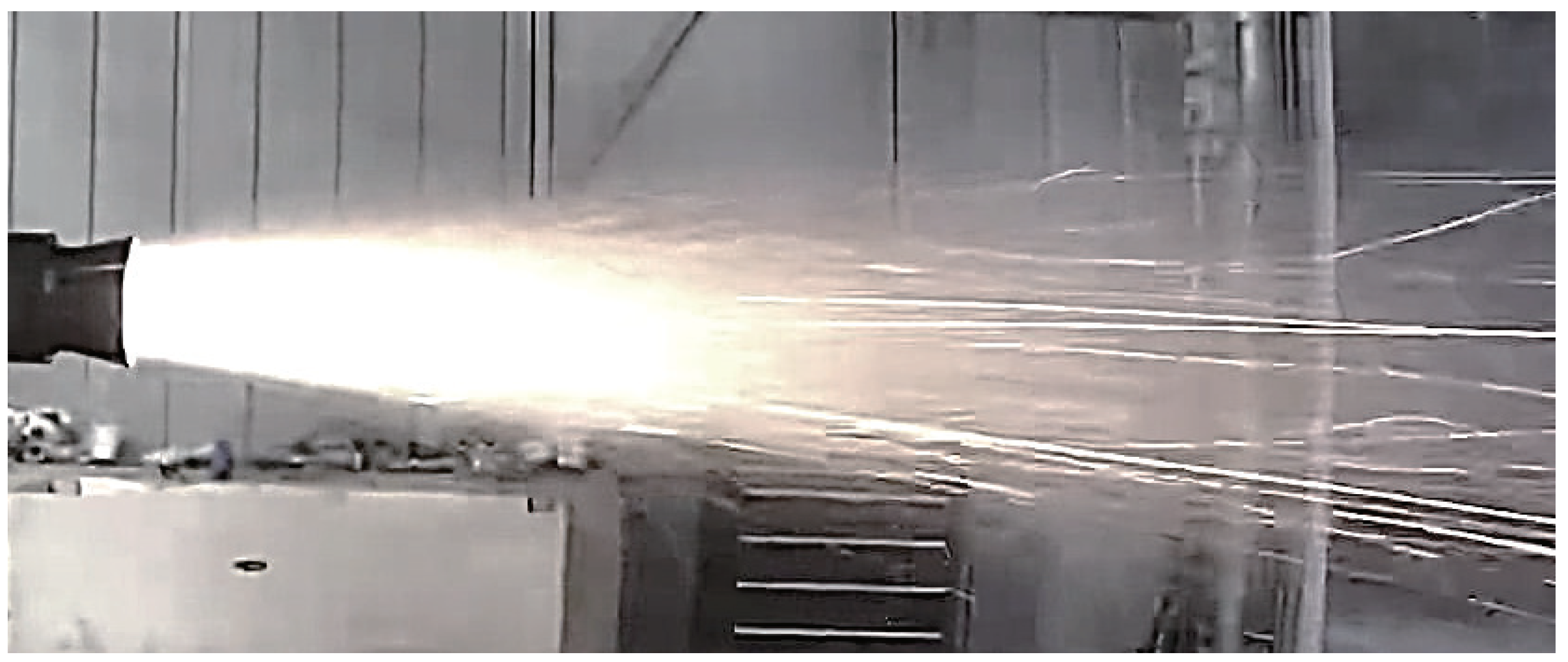
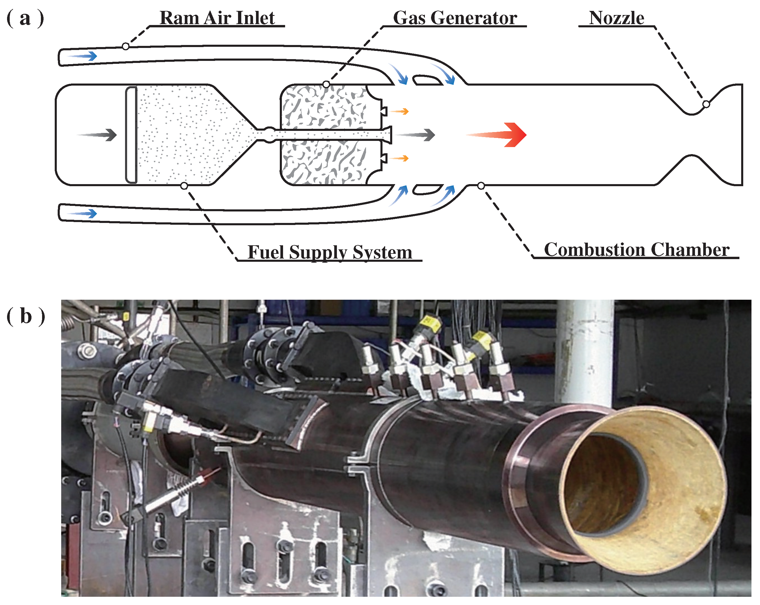
Figure 1 shows a photo of the flame from the nozzle taken during the experiment.
The flame was generally bright white, with orange-yellow edges and a small amount of white smoke. The flame color was uniform and symmetric, and the edges were regular. Thus, the combustion in the combustion chamber could be considered smooth. Some bright white streaks were observed farther away from the nozzle exit. These streaks were considered large droplets or particles that had not been wholly reacted or cooled in the combustion chamber. Due to their smaller specific surface area, these large aggregates cooled more slowly, leading to prolonged combustion reactions or cooling processes. These bright white streaks were more likely to be Al droplets in reaction,
droplets, or
particles at high temperatures [
26,
27,
28]. However, without appropriate temperature measurement methods or sampling analysis, it was impossible to identify and confirm the specific composition of these particles or droplets.
The main parameters obtained are presented in
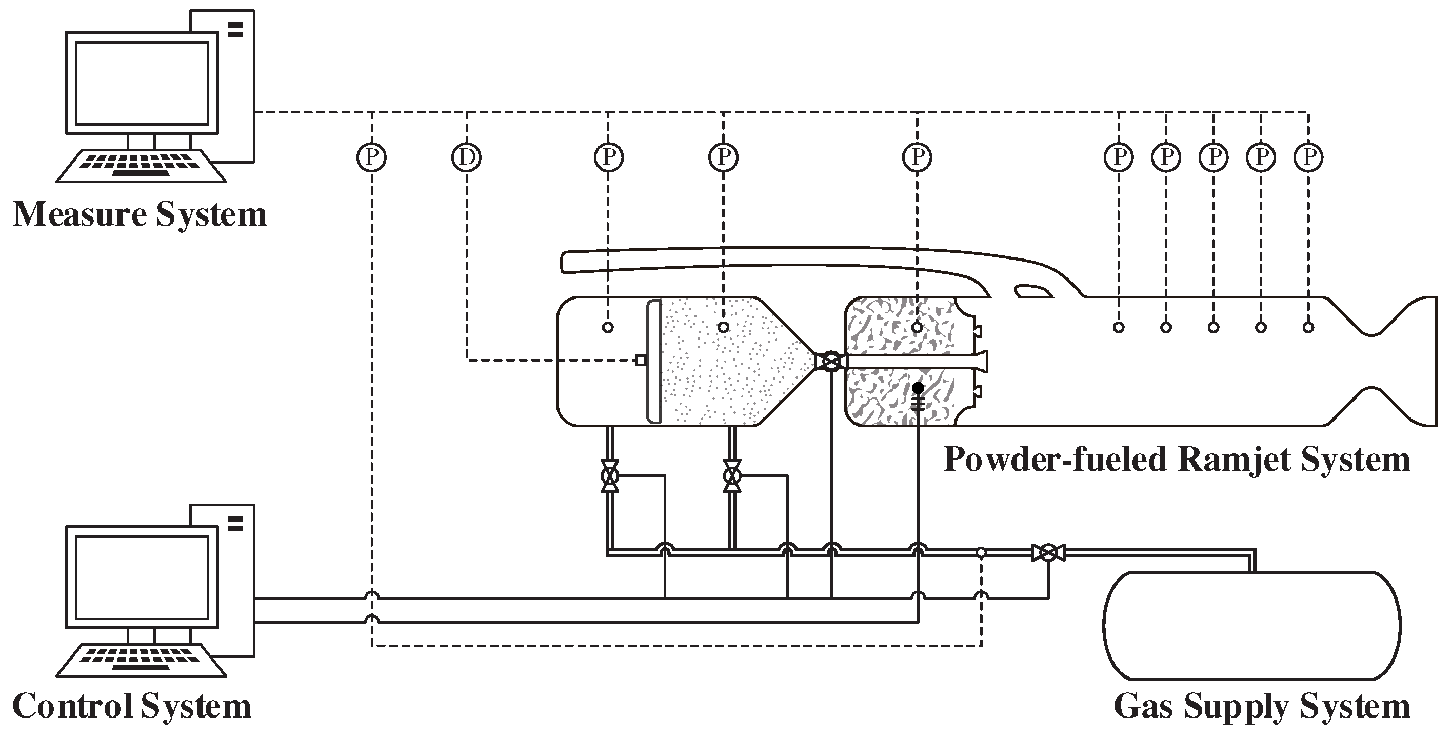
Table 1. These results were acquired using the measurement system and calculation methods mentioned earlier. The measured total pressure of the ram air was 0.40 MPa, and the total temperature was 606 K, which perfectly matches the design conditions. By measuring the static pressure within the gas generator, the gas flow rate during the operation of the gas generator was calculated. The fuel-rich gas flow rate was calculated to be 67 g/s, which also perfectly meets the design conditions.
The flow rate of the powder fuel calculated from the experiment was 87.70 g/s. This value showed a deviation of only 0.80% from the designed condition of 87.00 g/s. Consequently, the experimental air–fuel ratio of the powder-fueled ramjet was 19.39. The static pressure measurements at different axial positions in the combustion chamber indicated that the evolution of static pressure at various axial distances was almost identical. Within a range of 400 mm, the delay time of pressure evolution was less than 1 ms. Therefore, the measurement methods used in the experiment could not effectively distinguish the propagation of combustion signals. During the 10 s of self-sustaining combustion operation of the ramjet, the average static pressure in the combustion chamber was 0.2199 MPa. Based on these data, the performance of the powder-fueled ramjet and B–Al composite powder fuel could be calculated.
The combustion efficiency of the ramjet during operation could be evaluated using the characteristic exhaust velocity efficiency
, which was calculated using the following equation
Here,
is the experimental characteristic exhaust velocity of the ramjet.
is the theoretical characteristic exhaust velocity of the ramjet, representing its theoretical performance under complete combustion. This study calculated
using thermodynamic methods based on local conditions by CEA [
29,
30]. The equation for
is
where
is the static pressure of the combustion chamber, and
is the throat area of the ramjet’s nozzle.
is the mass flow rate of ram air, while
is defined to calculate the mass flow rate of the fuel and other components with fuel. The equation for
is
and are the mass flow rates of the powder fuel, fuel-rich gas, and fluidization gas, respectively. These components also contribute to the thrust of the powder-fueled ramjet.
The relevant performance metrics for the experiment could be calculated using the equations above. The results are shown in
Table 2. The characteristic exhaust velocity efficiency of this experiment reached 81.84%, which was higher than the experimental studies shown in
Table 3.
Overall, the experimental results demonstrate not only the feasibility and good performance of B–Al composite powder fuel, but also the advantages of the optimized powder-fueled ramjet configuration. This achievement also provides a new reference direction for the subsequent development and research of powder-fueled ramjets.
2.2. Deposit Analysis
In order to have a more detailed understanding of the combustion state of the B–Al composite powder fuel in the powder-fueled ramjet, this study conducted a series of analyses on the wall deposits in the combustion chamber after the ground test. This section will discuss the surface morphology, elemental composition, chemical state, and other information of two wall deposits located at the head (Sample 01) and the middle (Sample 02) of the combustion chamber. Sample 01 was located upstream of the ram air inlet, while Sample 02 was located downstream of the ram air inlet. The two samples represent deposits in the combustion chamber’s two typical reaction environments: the head environment upstream of the ram air inlet, and the mid-downstream environment after the ram air is supplemented. Thus, this study could comprehensively understand the state of deposits in the combustion chamber. To ensure the reliability of the sampling position, the sampling process selected deposits that were firmly attached to the wall, excluding any naturally peeled and movable parts.
In this study, the microstructure, elemental distribution, and chemical state of wall deposits in the ramjet combustion chamber were systematically studied using scanning electron microscopy combined with energy dispersive X-ray spectroscopy (SEM-EDS), X-ray diffraction (XRD), and X-ray photoelectron spectroscopy (XPS). A MIRA3 TESCAN model field emission scanning electron microscope (SEM) combined with an energy dispersive X-ray spectrometer (EDS) was used for morphological characterization. The sample preparation process glued the sample on a conductive adhesive. The probe for surface morphology characterization was a secondary electron detector (SE). The typical acceleration voltage was set to 20 kV, and the magnification was 50 kx. The EDS area scanning mode performed elemental mapping to resolve the surface composition heterogeneity. The study of crystalline phase composition used a Rigaku SmartLab model XRD instrument equipped with Cu K radiation ( Å). Diffraction patterns were recorded in the range 5–90° with a step size of 0.02° and a scan rate of 5° . Chemical state analysis was performed on a ThermoFisher ESCALAB Xi+ model XPS instrument equipped with a monochromatic Al K source ( eV). Survey spectra (0–1350 eV) were acquired with a 1 eV step size, while high-resolution spectra used a 0.05 eV step size. XPS curves were charge compensated by calibrating the C 1s peak (accidental carbon at 284.8 eV), and spectral deconvolution was performed using Shirley background subtraction.
2.2.1. SEM-EDS Analysis
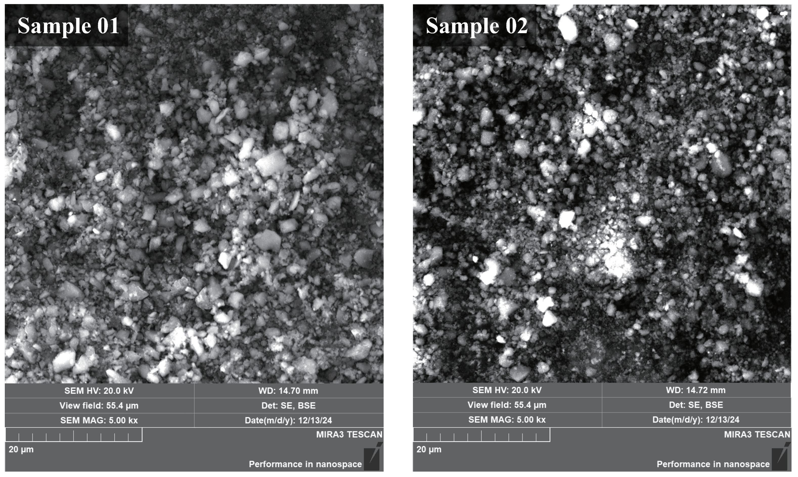
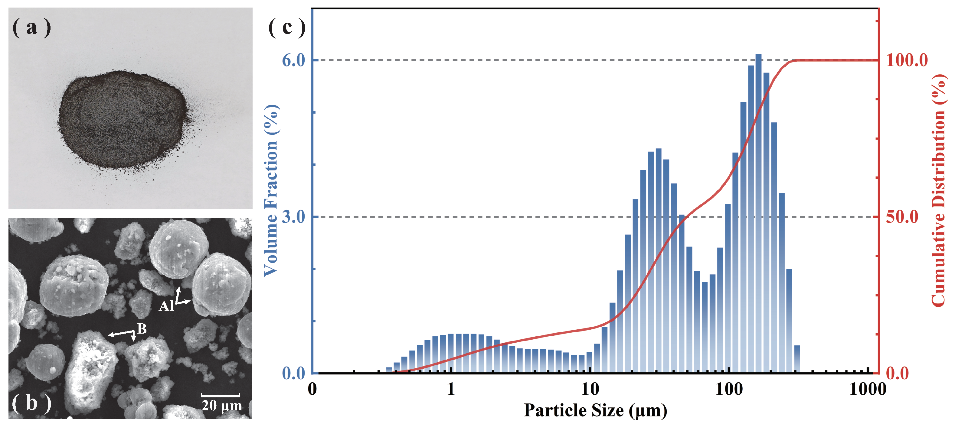
From the SEM images in
Figure 2, the surface morphology of Sample 01 and Sample 02 was similar overall. The surface particle size of the wall deposits was mostly distributed at 4
m and below. This particle size is significantly smaller than the characteristic particle size of the fuel itself. This indicates that the actual combustion reaction was carried out in basic units of smaller size. There may be two factors behind this phenomenon. One factor is that the B fuel itself is agglomerated nano-sized B powder. These agglomerated B powders are significantly dispersed in the combustion chamber. Another factor is the introduction of AP into the B–Al composite fuel. AP has a micro-explosion effect during combustion. The micro-explosion effect will reduce the particle size of the particles and increase the specific surface area of the solid particles, thereby improving the combustion performance. Judging from the particle size distribution on the surface of the deposit, the aim of reducing the basic size of the reaction unit and thus improving the fuel combustion performance was achieved.
The EDS results showed the element distribution of the samples, and the results are shown in
Table 4. From the difference between Sample 01 and Sample 02, Sample 01 had less B element and more O element, while N element and Al element accounted for a higher proportion. However, from the perspective of atomic ratio, it is not difficult to see that a considerable proportion of B element may not exist in the form of oxide, but in the form of a single substance. Assume that Al completely generates
and O only reacts with Al and B. In addition, assume that B only exhibits the two situations of generating
and not reacting. Then, the proportion of unreacted B in Sample 01 reached 75%. In Sample 02, this proportion reached 80%. This indicates that there was a large amount of unreacted B in the wall deposits. This may be because of the deposition of B that was not ignited, or it may be due to the deposition of B that had terminated combustion.
2.2.2. XRD Analysis
XRD can effectively analyze the composition of the crystalline phase materials in a sample.
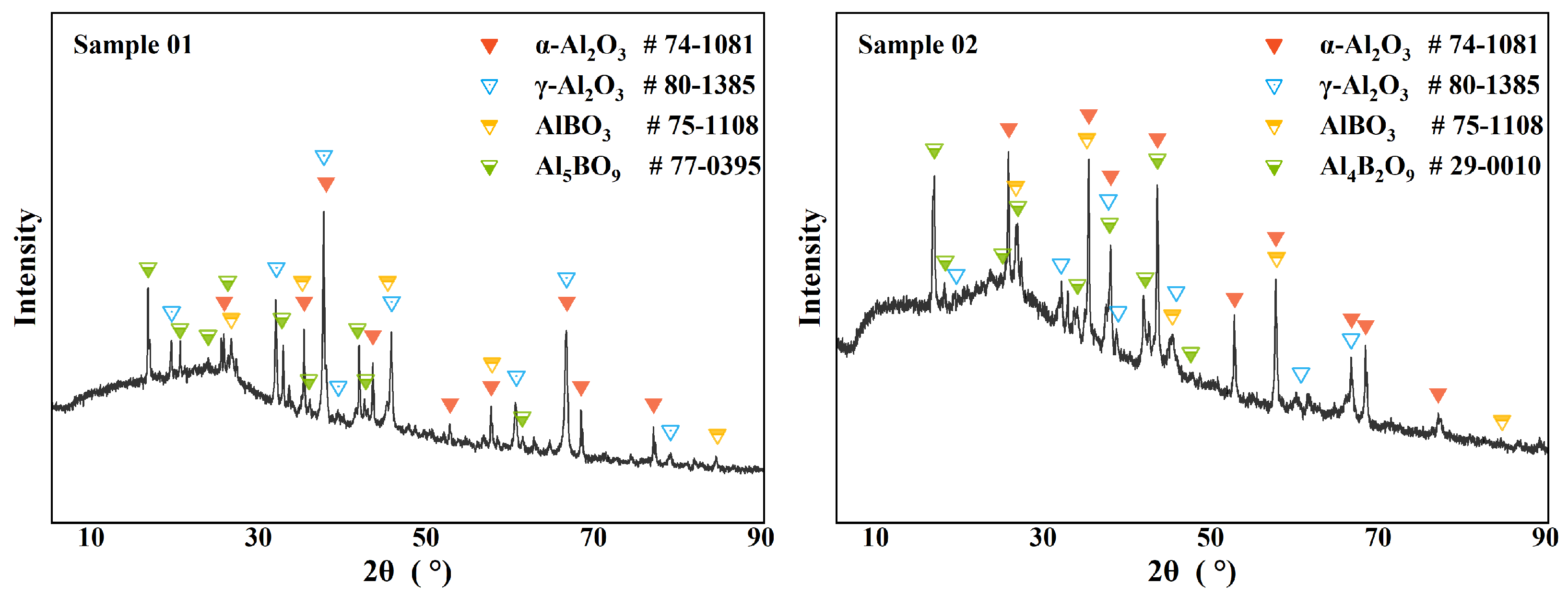
Figure 3 shows the XRD analysis results of the two samples. Previous studies have shown that the condensed phase products in the B-Al-N-O system usually include metal oxides, metal nitrides, and aluminoborates [
21,
22]. In this paper, the crystalline phase components obtained from the XRD analysis mainly included
,
,
,
, and
. Overall, the composition of the crystalline components of the two samples was similar, but the signal strength of different compositions was different. In Sample 01, the
signal was significantly stronger than the
signal. In Sample 02, the more stable
phase had a stronger signal. Considering the properties of the two alumina phases, the strong signal of
indicated a larger temperature gradient at the head of the combustion chamber, which allowed the unstable crystal phase to be preserved.
As for the borate, the crystals present in Sample 01 were mainly
, while the crystals present in Sample 02 were mainly
. Two pieces of information can be obtained from this. First, the ratio of
to
at the head and the middle of the combustion chamber was inconsistent, thus obtaining Al borates with different atomic ratios. Second, the wall temperature at the head and the middle of the combustion chamber was inconsistent, which affected the final stable crystals formed [
34,
35]. From the mutual conversion reaction, the wall temperature at the head of the combustion chamber was much higher than the wall temperature in the middle of the combustion chamber. On the other hand,
was analyzed in both samples. The formation temperature of this crystal was lower, and the required ratio of
to
was also very different from the two Al borate crystals mentioned above. This shows that the reaction inside the combustion chamber was not uniform. This uneven reaction has two aspects. On the one hand, the enrichment area where B and Al react was not uniform, and on the other hand, the intensity of the reaction was uneven. In addition, the appearance of these aluminoborates indicates that in most wall environments, the amount of
was always greater than or much greater than
. This difference in distribution density indicates that the oxidation reaction of Al was faster and had a higher reaction priority.
2.2.3. XPS Analysis
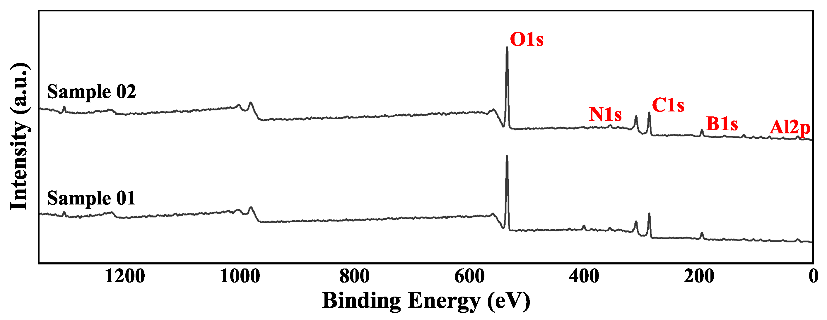
XPS is used to analyze the surface chemical state of a substance. Unlike XRD, it can analyze amorphous phase substances. But at the same time, XPS can only analyze shallow surface substances. The XPS total spectrum of the two samples is shown in
Figure 4. The parts for fine spectrum scanning were mainly Al 2p and B 1s. This section analyzes the high-resolution spectrum of these two parts.
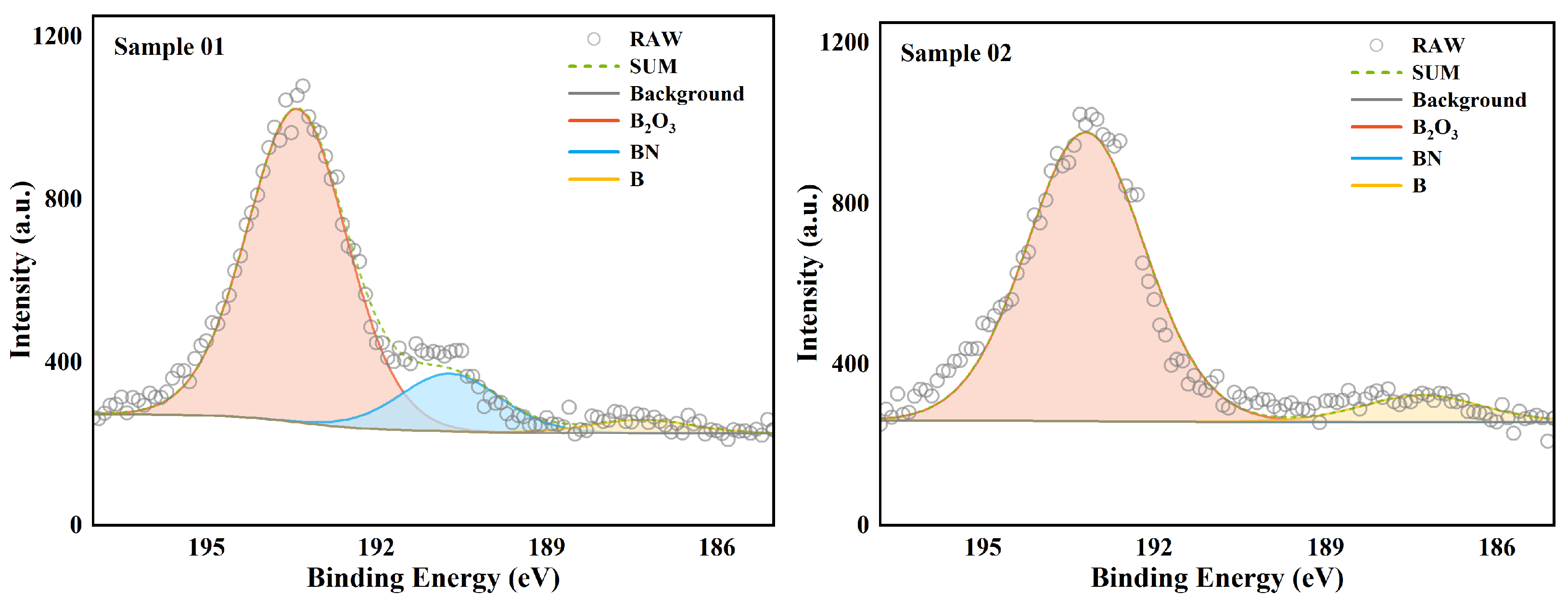
The high-resolution spectrum analysis of the 1s orbital of the B element is shown in
Figure 5. The data of the compounds with different valence states are listed in detail in
Table 5. Overall, the peak intensities of samples 01 and 02 were similar, and the main material composition of the surface was
. The difference was that there was a clear presence of BN in Sample 01. In Sample 02, there was no BN. This indicates that there was a local oxygen-poor high-temperature environment at the head of the combustion chamber. This caused some B and nitrogen elements to combine to form BN substances. Since the combustion chamber temperature does not reach the melting point of BN [
36], these BN stay in the wall deposits for a long time. In the middle of the combustion chamber, due to the supplementation of oxygen from the intake duct, the oxygen-poor environment no longer appears [
37]. Therefore, there was no BN peak in the XPS analysis of Sample 02. This phenomenon is consistent with the analysis results of EDS. As for B elementary substance, there was a clear distribution in both Sample 01 and Sample 02. This is very different from the analysis results of EDS in terms of area ratio. This difference shows that the distribution of B elementary substance in the sediment was uneven. Compared with the very small amount of B elementary substance on the surface, the proportion of B elementary substance inside the wall sediment was very high. These B elementary substances inside the wall sediment were wrapped by other substances and had difficultly in contacting oxygen and heat. The internal B elementary substance basically had no chance to participate in the combustion reaction again. From the perspective of surface chemical state, B existed mainly in the form of complete oxide on the surface of the wall sediment. This shows that the oxidation reaction of B could continue under the condition of sufficient oxygen.
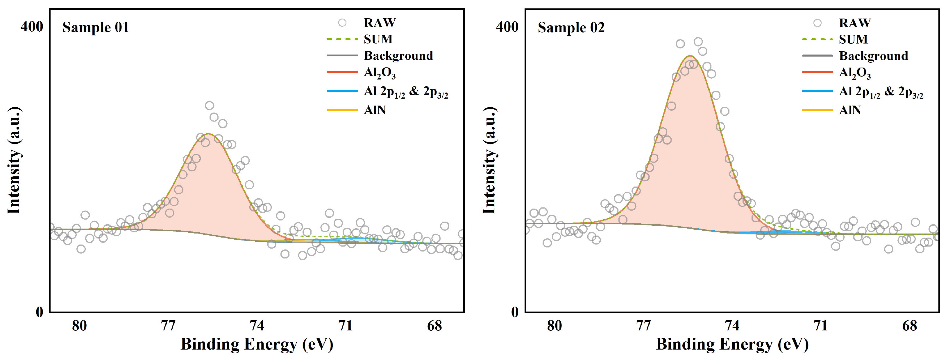
Similarly, the high-resolution spectrum analysis of the 2p orbital of Al is shown in
Figure 6. The data of compounds with different valence states are listed in detail in
Table 6. Unlike element B, Al element existed in both samples in the form of
as the absolute main form. In addition, a very small amount of Al elementary substance was detected. This weak signal indicates the existence of a local thin
film. The Al nitride AlN almost completely disappeared in the XPS analysis. This shows that under the same environmental conditions, the oxidation reaction priority and reaction rate of Al were higher than those of B. Therefore, in an oxygen-poor environment, AlN will appear later than BN. This conclusion is consistent with the conclusion obtained by XRD.
Through the analysis of the morphology and components of the wall deposits in this section, the combustion behavior of the B–Al composite powder fuel in the ramjet was clarified. First, the composite fuel could form smaller basic reaction units with a larger specific surface area, more favorable for the combustion reaction during the combustion process. Second, there were significant differences in the reaction rates, reaction priorities, and reaction enrichment areas of Al and B, which require further optimization. Third, B could achieve complete oxidation reaction under the condition of sufficient oxygen, but at the same time, how to solve the problem of B particles not reacting or the reaction being terminated due to the encapsulation effect blocking oxygen contact remains an important issue. In addition, the differences and changes in the combustion environment in the head and middle of the combustion chamber require more in-depth and comprehensive research.
