Abstract
Polysulfide-ferricyanide redox flow batteries (PFRFBs) are gaining significant attention in long-duration energy storage for their abundant availability and environmental benignity. However, the sluggish kinetics of the polysulfide redox reactions have tremendously constrained their performances. To address this issue, we developed a NiMoS catalyst-modified carbon felt (NiMoS-CF) electrode, which significantly accelerates the electrochemical reaction rates and enhances the cycling stability of PFRFB. Our PFRFB system, integrated with the NiMoS-CF electrode, exhibited an energy efficiency of 70% and a voltage efficiency of 87%, with a remarkable doubling of its cycle life as opposed to the pristine carbon felt (CF) electrode at a current density of 40 mA cm−2. Notably, during 2500 cycles of charge–discharge testing, we achieved an average coulombic efficiency exceeding 99%. These improvements in PFRFB performance can be attributed to the NiMoS-CF electrode’s large surface area, low resistance, and robust redox activity. This study offerings a novel approach for enhancing the electrochemical reaction kinetics and cycling stability in PFRFBs, laying a scientific foundation in the applications of practical PFRFBs for next-generation energy storage.
1. Introduction
As environmental pollution escalates and fossil fuel reserves diminish, there is a growing focus on harnessing eco-friendly and sustainable energy alternatives, such as solar and wind energy. To achieve the successful adoption of these intermittent resources, developing the long-duration energy storage systems is critically important [1]. Redox flow batteries (RFBs) have become an ideal solution for long-term energy storage due to their versatile design, high efficiency, durable cycle life, and excellent deep discharge abilities [2,3,4]. The current widely used flow battery is all-vanadium redox flow batteries (VRFBs), it still faces low energy density and cost fluctuations due to low vanadium solubility and limited resources [5,6,7,8]. Optimizing electrochemical performance, increasing energy and power density, lowering internal resistance, and improving electrolyte cycle stability are all critical for the development of RFBs for long-term energy storage.
Current research and development focuses on low-cost, high-energy density, and long-term RFBs [9]. Emerging neutral polysulfide-ferricyanide redox flow batteries (PFRFBs) are gaining popularity because of their high energy density (260 Wh L−1) and inexpensive cost (<19.26 $ kW h−1). Iron is abundant and affordable for large-scale energy storage [10,11,12]; Sulfur’s multielectron redox reaction and high theoretical energy density, when paired with iron, boost active ingredient usage and electrochemical performance [13,14], especially in S/Fe RFBs [15,16]. However, the battery performances of S/Fe RFBs including the voltage efficiency, energy efficiency, power density, and cycle life, are constrained by the sluggish kinetics of the polysulfide redox reactions. In the charging process, the large overpotential (>500 mV) and low energy efficiency (<50%) are resulted from the electrochemical reduction of polysulfide even with the moderate current densities (10–20 mA cm−2). This is a common challenge in polysulfide-based battery systems, which can be found in other sodium and lithium-sulfur batteries.
To facilitate the reduction of polysulfide, adding chemicals [17,18,19,20], electrolytes [21,22,23], etc. can increase its electrochemical characteristics and stability. Notably, redox processes that involve electrochemically active couples predominantly occur at the electrodes of RFBs. The dynamics of these redox reactions, which directly affect the performance of the battery, are affected by various factors associated with the physical and chemical characteristics of the electrodes, as well as their electrochemical behavior. These factors include surface roughness, wettability, durability, surface area, electrical conductivity, and the electrochemical activity. Several approaches have been investigated to enhance the kinetics of polysulfide ions. For example, Lan [13] improved the mass transfer and redox behavior of aqueous polysulfides by employing a nanostructured, self-assembled, hierarchically porous Co and N dual-doped carbon (OHP-Co/NC) as an electrocatalyst in an electrocatalytic reactor, resulting in a high power density of 110 mW cm−2 and 99.7% capacity retention, but the interfacial force between the carbon carrier and the active center in the catalyst is weak, which may result in the loss or inactivation of its active components, compromising the catalyst’s long-term stability. Sulfides have higher electrical conductivity than oxides, which allows for more efficient charge transfer [24], hance various metal sulfides like mesocrystalline NiS2 [25], CoS2/CoS [26,27], CuS [28] have been employed to boost the kinetics of polysulfide ions. Motivated by these pioneered studies, this work aims to develop novel S/Fe RFB system with accelerated kinetics of polysulfide redox reactions and long cycling life. It has not been reported, though, that NiMoS—a catalyst with strong stability and activity in electrocatalytic water splitting and catalytic hydrogenation and oxidation reactions [26,29,30]—is used in polysulfide-ferricyanide redox flow batteries. Here, we introduce NiMoS catalysts modified carbon felt (NiMoS-CF) as an anode electrode, capitalizing on the catalytic properties of metal sulfides to enhance polysulfide redox processes. NiMoS-CF demonstrated good charge transfer and catalytic performance for polysulfide redox processes. By directly growing electrocatalytic materials on carbon felt (CF), we created modified electrodes without binders, avoiding the negative impacts of adhesives. The PFRFB, equipped with the NiMoS-CF electrode, exhibited improved electrochemical reaction rates, energy density and cycling stability, with a 70% energy efficiency, a coulombic efficiency of over 99% and the cycle life of 2500 cycles at 40 mA cm−2. In contrast, the PFRFB with pristine CF as the negative electrode ended after 1300 cycles, leading to a faster capacity decline.
2. Results and Discussion
Figure 1a illustrates the configuration of S/Fe redox flow battery, in which K2S and K3[Fe(CN)]6 are utilized as the anolyte and catholyte, respectively. The catholyte and anolyte are composed of the redox couples [Fe(CN)6]4−/3− and S22−/S2−, respectively, with KCl as the supporting electrolyte. As demonstrated in the preparation process of the NiMoS-CF electrode, a one-step hydrothermal process was employed to synthesize the NiMoS catalyst on the CF, avoiding the negative impacts of the adhesive nafion which is commonly used. It is hypothesized that the catalyst can significantly extend the surface area of the original CF, provide new reaction sites, and improve the conductivity of the electrode [31]. The electrochemical reversibility of the species involved in the redox reactions. was assessed using CV tests. The following redox reactions are represented by one pair of redox peaks in the respective positive and negative electrolyte. As shown in Figure 1b,c, the reversibility of the reaction is usually judged by the symmetry of the curve [32], the redox couples [Fe(CN)6]4−/3− and S22−/S2− show good reversibility and exhibit well-defined redox peak.
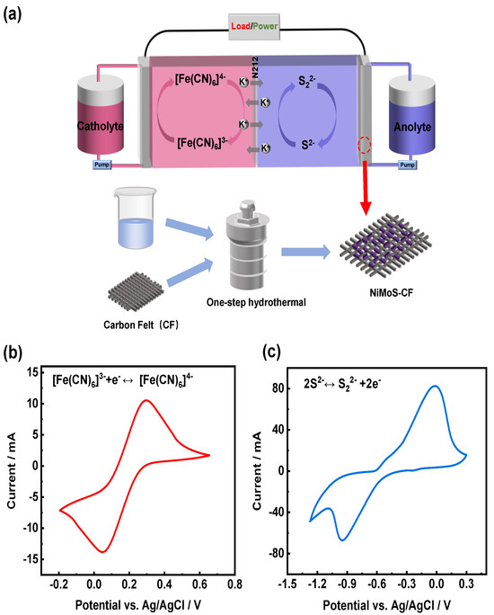
Figure 1.
(a) Schematic illustration of the S/Fe redox flow battery system; CV curves of (b) ferricyanide/ferrocyanide and (c) sulfide/polysulfide in 1.0 M KCl electrolyte at 10 mV s−1.
2.1. Structure and Morphology of NiMoS-CF Electrode
The SEM photographs reveal significant morphological distinctions between pristine CF and NiMoS-CF, indicating effective nucleation and growth of NiMoS on the surface. Specifically, the pristine CF (Figure 2a) exhibits a clean and smooth surface, whereas the NiMoS-CF (Figure 2b,c), after 12 h of hydrothermal treatment, displays a rough surface. Consequently, the electrode surface becomes relatively rough and this morphology not only provides additional active sites for redox reactions but promotes close contact with the electrolyte, thereby accelerating the kinetics of these reactions [33,34]. In the TEM image shown in Figure 2d, the distinct nanorods were observed. The spatially uniform distribution of Ni, Mo, and S elements can be revealed by HAADF-STEM analysis coupled with EDS mapping (Figure 2e–h). In Figure 2i, the HR-TEM image exhibits obvious lattice fringes with interplanar distances of 2.65 Å and 2.43 Å, aligning with the d-spacing of (269) and (140) planes of NiMoS. These crystalline planes are evident from the XRD patterns. Compared with the pristine CF and the standard NiMoS patterns, not only the diffraction peak from CF, but also the main peak of NiMoS can be obviously observed in the prepared NiMoS-CF, which confirms that the NiMoS catalyst is successfully grown on the CF (Figure 2j).

Figure 2.
SEM images of the (a) pristine CF and (b,c) NiMoS-CF; (d) TEM image of NiMoS-CF; (e) HAADF-STEM image of NiMoS-CF; (f–h) EDS mapping of Ni, Mo and S; (i) HR-TEM image of NiMoS-CF; (j) XRD patterns of pristine CF and NiMoS-CF.
Also, significant differences in hydrophilicity were identified before and after the NiMoS modification on the CF. The contact angle of the pristine CF was 140° (Figure 3a), indicating that the surface of the material was lyophobic, while NiMoS-CF rapidly absorbed droplets during the test, showing hydrophilicity (Figure 3b). Specifically, the increased wettability facilitates better electrolyte accessibility and more efficient mass transport of reactants to the active sites, reduced the charge transfer resistance.
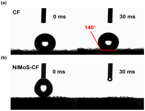
Figure 3.
Contact angle measurements of (a) pristine CF and (b) NiMoS-CF.
The XRD patterns and XPS survey spectrum of NiMoS catalyst can be found in Figures S2 and S3. The unindexed peaks in the XRD pattern are attributed to the presence of minor secondary phases and impurities in the catalyst such as MoS2 [35]. These phases likely arise from incomplete crystallization or residual precursors during the synthesis process. XPS analysis confirmed the presence of Ni, Mo, and S elements within the catalyst. The Ni 2p XPS spectra display two shakeup satellites (labeled Sat.) at 859.9 and 877.6 eV, along with two spin-orbit doublets, corresponding to Ni 2p3/2 (Ni2+ at 853.5 and Ni3+ at 855.2 eV) and Ni 2p1/2 (Ni2+ at 871.3 and Ni3+ at 873.3 eV) [36,37,38]. The Mo 3d XPS spectra are shown in Figure S3c, with peaks at 232.2 eV and 235.2 eV corresponding to Mo 3d5/2 and Mo 3d3/2, respectively [39]. The spectra of S 2p is illustrated in Figure S3d. Figure S3d illustrates the S 2p XPS spectra, where the peaks at 163.5 eV and 162.3 eV are assigned to 2p1/2 and 2p3/2 of S2−, and the peak at 168.6 eV is indicative of sulfate species [40,41].
2.2. Catalytic Performance of NiMoS-CF Electrode for Sulfur Ions
2.2.1. Electrochemistry Tests
The electrochemical response of CF and NiMoS-CF to the redox reaction of K2S was investigated in Figure 4a,b, detailed CV data are shown in Table S1, respectively. At the equilibrium potential of −0.455 V, the major redox reaction is attributed to the S22−/S2− pairs [42]. At all test rates, the current densities of the main redox peaks on NiMoS-CF are higher than those on pristine CF. With a sweep rate of 10 mV s−1, both pristine CF and NiMoS-CF present distinct redox peaks (Figure 4c). These findings suggest that the surface coverage of NiMoS enhances the electrochemical activity. The catalyst surface area is a key determinant of electrochemical performance, as indicated in previous studies [28,43,44,45]. The glassy carbon electrode (GCE) provides a flat, well-defined surface area that allows precise evaluation of the intrinsic catalytic activity of NiMoS. To minimize confounding factors such as substrate porosity, mass transport limitations, or uneven catalyst distribution that may arise when directly coating fibrous substrates like CF, replacing a glassy carbon electrode (GCE) for the working electrode (Figure S4), which is less susceptible to external factors and exhibits enhanced conductivity, multiple polysulfide redox peaks were observed (Figure S5). The NiMoS-GCE shows a significant peak-to-peak separation in the CV, this observation can be attributed to the intrinsic limitations of CV in capturing subtle kinetic improvements, especially in systems where substrate effects dominate. The GCE data and carbon felt-based results collectively provide a comprehensive understanding of both catalyst efficiency and scalability. According to the result, a more complex electrochemical reaction occurred among the polysulfides, and the valence states of S ions not only include S22−/S2− but may also involve additional polysulfide species, such as Sx2− (x = 2–8). These redox reactions are directly linked to the energy conversion efficiency of the battery, as demonstrated in various sulfur-based batteries [26,31].

Figure 4.
CV profiles for (a) pristine CF and (b) NiMoS−CF at various scan rates; (c) CV curves of pristine CF and NiMoS−CF at a scan rate of 10 mV s−1; (d) peak currents fitting lines for the S22−/S2− redox pair on pristine CF and NiMoS−CF plotted against the square root of the scan rates; (e) Nyquist plots from the resulting EIS of pristine CF and NiMoS−CF with fitting curves; (f) comparison of resistance values derived from the Nyquist plots.
Since the diffusion constant of the active ion is proportional to the ratio of and , the linear lines developed for NiMoS-CF exhibit steeper slopes (Figure 4d), suggesting that the transfer process of active ions on CF and NiMoS-CF is controlled by diffusion, and the catalyst changes the diffusion rate rather than the mode of control. The resistance of both pristine CF and NiMoS-CF were characterized through electrochemical impedance spectroscopy (EIS) tests, as illustrated in Figure 4e. Furthermore, the measured charge transfer resistance (Rct) of the NiMoS-CF (524 mΩ) was lower than that of the pristine CF (3768 mΩ), showing that the redox kinetics of the S22−/S2− pair are enhanced on the NiMoS-CF and significantly accelerates the redox reaction (Figure 4f, Table S2). In addition, in Figure 4e, the fitting curve of the high frequency region is added for better comparison.
ECSA refers to the Electrochemical Active Surface Area: a higher ECSA value implies that the effective area of the electrode is greater. Furthermore, the Tafel slope was quantitatively evaluated. The lower Tafel slope implies that the kinetics of the electrode are faster and its catalytic activity is higher. In the non-Faraday region, non-faraday capacitance of electrode is positively correlated with ESCA. If the measured capacitance is significantly lower than the theoretical value, it may indicate pore blockage, poor electrical conductivity, or low ion accessibility. In addition, the high double layer capacitance means that charge storage achieves a fast response through the adsorption/desorption of electrolyte ions on the electrode surface. CV curves were obtained by CV testing at different sweep speeds (Figure 5a,b), which were subsequently analyzed to determine the double-layer capacitance () for the different electrodes (Figure 5c). The results of the calculations for (), ECSA, and Tafel slopeare summarized in Table 1. These findings demonstrate that NiMoS-CF possesses a larger double-layer capacitance, and the electrochemical area estimated from () is greater than that of pristine CF. The decreased Tafel slope (Figure 5d) also indicates that NiMoS-CF exhibits faster reaction kinetics.
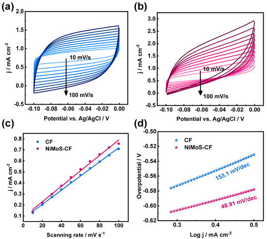
Figure 5.
CV profiles for (a) pristine CF and (b) NiMoS−CF in non-Faraday intervals; (c) the corresponding comparison of different electrodes; (d) Tafel slopes for different electrodes.

Table 1.
Diffusion rates of different electrodes.
Furthermore, the structural properties of NiMoS catalyst, such as abundant edge active sites, provide excellent catalytic sites that enhance the adsorption and dissociation of sulfur ions, thereby accelerating the rate of redox reactions. During the reaction, sulfur is removed off the catalyst surface at a lower level, and the active metals Mo and Ni become unsaturated with ligands, generating vacant sites and enhancing the diffusion rate of sulfur ions [46].
To further investigate proliferation, the Randles–Sevcik equation was used to quantitatively calculate the diffusion coefficients of different electrodes. The data in Table 1 indicate that the NiMoS catalyst enhances transport capacity of ions, and the ions in the solution exhibit a greater diffusion capacity when utilizing the NiMoS-CF.
The standard rate constants can be used to determine the redox reaction’s kinetics. Higher values indicate faster kinetics, reduced energy requirements, and lower overpotential, which are critical for the high-performance RFBs [47]. Reversible electrochemical reactions exhibit high charge transfer rates ( > 10−1 cm s−1). Although Nicholson approach is the preferred method for calculating standard rate constants in reversible systems, the Lavagnini modification of Nicholson method in Equation (5) is more suitable for peak-to-peak separation over 200 mV in this experiment. Table 1 presents the results derived from the CV test. The higher redox kinetic parameters suggest that chemical reactions between the redox pairs are more likely to occur, allowing the system to reach equilibrium in a shorter amount of time with NiMoS-CF electrodes [47].
2.2.2. Flow Battery Tests
To assess the impact of electrodes on battery performance, PFRFBs were constructed with pristine CF and NiMoS-CF electrode, respectively. According to Figure 6a, NiMoS-CF cell exhibited significantly greater energy efficiency than pristine CF cell in the current density ranging from 20 to 100 mA cm−2. At higher current densities, NiMoS-CF has a more pronounced positive effect compared to pristine CF serves as an anode. Specifically, the polarization of NiMoS-CF is lower than that of pristine CF RFBs. The energy efficiency is approximately equivalent to that of pristine CF cells when the current density above 100 mA cm−2, and a similar trend is observed in the cells’ voltage efficiency (Figure 6b). Consequently, the voltage loss in NiMoS-CF-based PFRFB is reduced as the polarization effect diminishes.

Figure 6.
(a,b) The rate performances of PFRFBs with pristine CF and NiMoS−CF as anode, respectively; (c) polarization curves of PFRFBs with pristine CF and NiMoS−CF; (d) charge/discharge voltage curves of PFRFBs with pristine CF and NiMoS−CF; (e) cell performance of PFRFBs with pristine CF and NiMoS−CF.
This assumption was supported by the polarization curve test conducted at 50% SOC (Figure 6c). The cell equipped with NiMoS-CF demonstrated lower charge voltage and higher discharge voltage in polarization tests, and the reduction of overpotential will lead to the improvement of EE.
The charging and discharging voltage curves in Figure 6d determine that the charging curve of the pristine CF electrode differs from that of the NiMoS-CF electrode, where the voltage initially decreases and then rises. It is believed that this behavior results from the electrochemical process that occurs when redox ions of various valence states diffuse to the electrode surface. A concentration gradient is created when the concentration difference of ions in the spatial domain decreases because the diffusion rate of ions on the electrode surface is less than the reaction rate. Concentration polarization and related losses are caused by this gradient [48]. At a current density of 100 mA cm−2, battery based on NiMoS-CF exhibit lower charge and higher discharge plateaus compared to that based on pristine CF, verifying the battery with NiMoS-CF as the anode has reduced polarization. The curves confirm that NiMoS-CF electrode perform significantly better than pristine CF electrode; Specifically, the electrocatalytic activity of the pristine CF electrode is markedly improved following modification with NiMoS catalyst.
To further assess and compared the characteristics of NiMoS-CF and pristine CF as negative electrodes, the CE and EE of the cells were measured at 40 mA cm−2 in Figure 6e. The data revealed that the battery equipped with NiMoS-CF electrode had an energy efficiency (EE) of 71% during the first cycle and 40% after 2500 cycles. That was higher than that of the battery with pristine CF electrode, which had an EE of 64% at the beginning of the cycle and 40% when it became inoperative due to severe capacity degradation after 1300 cycles. It is evident that the battery is capable of maintaining a stable voltage plateau and capacity output over numerous cycles of usage and is not prone to rapid performance degradation.
It is worth noting that the NiMoS-CF electrode’s EE declined after 2500 cycles, owing primarily to CF degradation and electrolyte contamination. During the extended cycle, the CF may corrode or wear mechanically. As the cycle advances, the accumulation of chemical byproducts or impurities in the electrolyte can impede mass transfer, increase overpotential, and result in decreasing efficiency.
When compared to other representative batteries, the PFRFB with NiMoS-CF reported in this paper demonstrates exceptional performance, the capacity retention rate is as high as 99.9%, as illustrated in Table S3. In conclusion, following the modification of the NiMoS catalyst on the pristine CF electrode and subsequent battery testing, the cycle life, EE, and VE values of the battery are significantly enhanced.
3. Experimental
3.1. Materials
Nickel chloride hexahydrate (NiCl2·6H2O, AR > 98.0%) was obtained from Shanghai McLean Biochemical Science and Technology Company (Shanghai, China). Sodium molybdate dihydrate (Na2MoO4·2H2O, AR > 98.0%), thiourea (CH4N2S, AR > 99.0%), ethanol absolute (C2H6O, AR > 99.5%), potassium ferricyanide (K3[Fe(CN)6], AR > 99.5%), potassium polysulfide (K2S, AR ≥ 40%), and potassium chloride (KCl, AR > 99.0%) were ordered from Sinopharm Chemical Reagent Company (Shanghai, China). The above chemicals were used directly for experiments without any purification. Nafion 212 membrane was provided by Jiangsu Kerun Membrane Materials Company (Suzhou, China). Prior to use, the commercial Nafion 212 was subjected to boiling in a 1.0 M KOH solution at 80 °C for 1 h. This process facilitated the transformation of the membrane from a proton (H+) to a potassium (K+) form of cation-exchange membrane. Before using, the treated Nafion 212 was soaked in deionized (DI) water.
3.2. Preparation of NiMoS Catalyst and NiMoS-CF
The one-step hydrothermal method was used to prepared the NiMoS catalyst and NiMoS-CF electrode. 0.3 mmol L−1 NiCl2·6H2O, 0.3 mmol L−1 Na2MoO4·2H2O, and 0.25 mmol L−1 of CH4N2S were added to 100 mL of deionized water. The solution was magnetically agitated at room temperature (~25 °C) until dissolved. Different sizes of carbon felts (1.5 × 1.5 cm2 and 2.0 × 2.0 cm2) with the above solution were transferred to a 100-mL Teflon-lined autoclave. The reactor was kept in an oven at 180 °C for 24 h. Finally, the NiMoS catalyst and NiMoS-CF were collected, rinsed with DI water, and dried at 60 °C for 10 h before using.
3.3. Material Characterizations
The morphologies of pristine CF and NiMoS-CF electrodes were investigated by scanning electron microscopy (SEM, Zeiss GeminiSEM 300, Zeiss, Oberkochen, Germany). The structural and chemical information of the NiMoS-CF electrode were elucidated using high-resolution transmission electron microscopy (HR-TEM, model JEOL F200, JEOL, Tokyo, Japan) at an operating voltage of 200 kV. This analysis included high-angle annular dark-field scanning transmission electron microscopy (HAADF-STEM, JEOL) for imaging, companied by energy-dispersive X-ray spectroscopy (EDS) for elemental mapping. The characteristic diffraction peaks of pristine CF and NiMoS-CF were employed by X-ray diffraction (XRD, D8 ADVANCE and DAVINCI DESIGN, Karlsruhe, Germany) in the range of 3–90° with Cu Kα (λ = 1.5418 Å) radiation, an accelerating voltage of 40 kV and a current of 40 mA. The X-ray photoelectron spectrometer (XPS, ESCALAB250Xi, Thermo Fisher Scientific, Waltham, MA, USA) was performed for high-resolution XPS measurements equipped with Al Kα source. Hydrophilicity of pristine CF and NiMoS-CF were measured by contact angle test (CA, Dataphysics-OCA20, Stuttgart, Germany).
3.4. Electrochemical Measurements
Cyclic voltammetry (CV) experiments were conducted within a three-electrode configuration using an electrolyte solution composed of 50 mmol L−1 K2S and 1.0 mol L−1 KCl. The setup included either pristine CF or NiMoS-CF (with dimensions of 1.5 × 1.5 cm2) as the working electrode, pristine CF (2 × 2 cm2) as the counter electrode, a Ag/AgCl electrode as the reference electrode, with test voltages in the range of −1.3 to 0.3 V and scanning rates between 5 and 50 mV s−1 on Chenhua Chi660e Electrochemical Workstation (CH Instrument, Shanghai, China). The electrochemical impedance spectroscopy (EIS) measurements were done in the amplitude of 15 mV and the frequency range of 10 MHz to 100 kHz. The glassy carbon electrode (GCE) was used in the same electrolyte system as working electrode, which was drop-coated with a catalyst ink of 3 mg NiMoS + 2 mg carbon powder + 80 µL Nafion + 900 µL anhydrous ethanol. S/Fe RFB cells (Figure S1) were fabricated using pristine CF or NiMoS-CF as the anode (2 × 2 cm2) and pristine CF (2 × 2 cm2) as the cathode, separated by a Nafion 212 ion-exchange membrane. The anolyte was prepared as a 40 mL aqueous solution containing 2.0 mol L−1 K2S and 2.0 mol L−1 KCl, while the catholyte consisted of 40 mL of 1.0 mol L−1 K3[Fe(CN)6] and 2.0 mol L−1 KCl. Both electrolytes were circulated through the cell at a constant flow rate of 70 mL min−1 during electrochemical testing. Tests of rate performance and long-term charge/discharge cycle were conducted on LAND battery test system (CT3002K, LAND Electronics, Wuhan, China).
At current densities ranging from 20 to 100 mA cm−2, the rate performance at 50% State of Charge (SOC) was determined. For each specified current density, a series of eight charge/discharge cycles were executed to record the values of Coulombic Efficiency (CE), Voltage Efficiency (VE) and Energy Efficiency (EE). In constant current mode, long-term charge/discharge cycling experiments were conducted at 40 mA cm−2 within the voltage in the range of 0.3 to 1.8 V. Polarization curves were obtained on the same device.
3.5. Electrochemical Calculation
The diffusion coefficients for different electrodes were quantified according to the Randles-Sevcik equation [49]:
Or if the solution is at 25 °C [50]:
where represents the peak current in amperes, denotes the number of electrons involved in the redox process (commonly 1), is the diffusion coefficient (cm2 s−1), is the scan rate (V s−1), is the electrode area (cm2), and is the concentration of the substance to be measured (mol cm−3).
The Nicholson approach [51] was used to calculate standard rate constants k0 for various electrodes.
The dimensionless kinetic parameter, denoted as , is derived from [52], where is the transfer coefficient, is the number of electrons transferred in the redox process, is the Faraday constant. and have their usual meanings. Typically, it is reasonable to assume that the diffusion coefficients for both the oxidized () and reduced () forms of the mediator are nearly identical, and the reduction and oxidation kinetics are relatively symmetrical ( ∼ 0.5) [53].
From Equation (3), the slope of a plot of versus can be used to determine . The values of at different peak separations can be estimated practically using Equation (4).
where is the redox peak current potential difference (V).
The Lavagnini method [54] is an improvement on the Nicholson method and can achieve peak-to-peak separation above 200 mV which is more suitable for this experiment:
where is the transfer coefficient for the electrode process [55].
ECSA is the Electrochemical Active Surface Area, a higher ECSA value implies that the electrode’s effective area is greater.
where is the double capacitive electric layer, is the differential capacitance of the smooth metal, which is taken at 0.04 mF cm−2 in this research [56], and is the geometric surface area of the electrode.
In this experiment, all currents in non-faradic region were assumed to be non-faradic currents. The region for non-faradic is −0.1–0 V (vs. KCl saturated Ag/AgCl). The current is obtained at the middle point of potential range from CV curves at 0.01–0.1 V s−1. And of the system is taken as the average of absolute value of charging current. The electrolyte used in ECSA tests is 0.05 M K2S with 1.0 M KCl.
4. Conclusions
In summary, we have successfully fabricated NiMoS catalyst on the carbon felt electrode via a one-step hydrothermal method. The electrochemical reaction kinetics and charge transfer behaviors of the obtained NiMoS-CF electrode were improved by the NiMoS modification, resulting in the accelerated kinetics of polysulfide redox reactions. The integrated PFRFB with NiMoS-modified carbon felt electrode as the anode, exhibited a significant improvement in the energy density and cycle stability, including an energy efficiency of 70%, voltage efficiency of 87%, outperforming the pristine CF-based battery with corresponding values of 64% and 84%, respectively. Furthermore, the cycle life of the PFRFB was extended to 2500 cycles with a coulombic efficiency consistently maintained above 99% at 40 mA cm−2. This research provides a strategy for enhancing the performance of the S/Fe RFBs by employing sulfide bimetallic catalyst as the electrode booster, offering a promising direction for developing the cost-effective and high-performance energy storage systems.
Furthermore, while the three-electrode test described in this study can be utilized for high-precision electrochemical measurements, it is susceptible to effects from solution resistance, voltage window, and temperature. To avoid such impacts in future work, the test error will be addressed to the greatest extent possible.
Supplementary Materials
The following supporting information can be downloaded at: https://www.mdpi.com/article/10.3390/molecules30061219/s1; Figure S1: Photograph of the NiMoS-S/Fe cell stack; Figure S2: XRD pattern of NiMoS catalyst; Figure S3: (a) XPS survey spectrum of NiMoS catalyst; high-resolution spectra for (b) Ni 2p, (c) Mo 3d and (d) S 2p spectra of NiMoS catalyst; Figure S4: Glassy carbon electrode with NiMoS catalyst; Figure S5: CV curves of the original GCE and NiMoS modified GCE at 10 mV s−1; Table S1: Kinetic parameters of S22−/S2− from CF and NiMoS-CF’s CV data. Related to Figure 4a,b; Table S2: Fitting results for the as-prepared samples from the Nyquist plots; Table S3: An overall comparison with other representative RFBs. References [10,13,16,27,31,32,42,46,57,58,59,60,61] are cited in the Supplementary Materials.
Author Contributions
Conceptualization, D.M.; writing—original draft preparation, B.L.; writing—review and editing, H.M.; visualization, Z.Z.; visualization, F.W.; funding acquisition, project administration, Y.C.; funding acquisition, supervision, J.A.; resources, supervision, F.X.; funding acquisition, L.X. All authors have read and agreed to the published version of the manuscript.
Funding
This study received financial support from the National Natural Science Foundation of China (Grant No. W2432038), the special fund of Advantageous characteristic disciplines (Group) of Hubei Province, the Excellent Young and Middle-aged Scientific and Technological Innovation Team Project of Colleges and Universities in Hubei Province (Grant No. T2023041), China Postdoctoral Science Foundation (Grant No. 2023M730399), the Guangdong Foundation of Basic and Applied Foundation (2024A1515012826) and Guangdong Province Key Construction Discipline Research Ability Improvement Project (2024ZDJS027).
Institutional Review Board Statement
Not applicable.
Informed Consent Statement
Not applicable.
Data Availability Statement
Data will be made available on request.
Conflicts of Interest
The authors declare no known competing financial interests or personal relationships that could have appeared to influence the work reported in this paper.
References
- Twitchell, J.; DeSomber, K.; Bhatnagar, D. Defining long duration energy storage. J. Energy Storage 2023, 60, 105787. [Google Scholar] [CrossRef]
- Yuan, Z.; Liang, L.; Dai, Q.; Li, T.; Song, Q.; Zhang, H.; Hou, G.; Li, X. Low-cost hydrocarbon membrane enables commercial-scale flow batteries for long-duration energy storage. Joule 2022, 6, 884–905. [Google Scholar] [CrossRef]
- Zuo, P.; Ye, C.; Jiao, Z.; Luo, J.; Fang, J.; Schubert, U.S.; McKeown, N.B.; Liu, T.L.; Yang, Z.; Xu, T. Near-frictionless ion transport within triazine framework membranes. Nature 2023, 617, 299–305. [Google Scholar] [CrossRef]
- Yang, M.; Xu, Z.; Xiang, W.; Xu, H.; Ding, M.; Li, L.; Tang, A.; Gao, R.; Zhou, G.; Jia, C. High performance and long cycle life neutral zinc-iron flow batteries enabled by zinc-bromide complexation. Energy Storage Mater. 2022, 44, 433–440. [Google Scholar] [CrossRef]
- Xing, F.; Liu, T.; Yin, Y.; Bi, R.; Zhang, Q.; Yin, L.; Li, X. Highly Active Hollow Porous Carbon Spheres@Graphite Felt Composite Electrode for High Power Density Vanadium Flow Batteries. Adv. Funct. Mater. 2022, 32, 2111267. [Google Scholar] [CrossRef]
- Yu, Z.; Jia, X.; Cai, Y.; Su, R.; Zhu, Q.; Zhao, T.; Jiang, H. Electrolyte engineering for efficient and stable vanadium redox flow batteries. Energy Storage Mater. 2024, 69, 103404. [Google Scholar] [CrossRef]
- Bui, T.T.; Shin, M.; Abbas, S.; Ikhsan, M.M.; Do, X.H.; Dayan, A.; Almind, M.R.; Park, S.; Aili, D.; Hjelm, J.; et al. Sulfonated para-Polybenzimidazole Membranes for Use in Vanadium Redox Flow Batteries. Adv. Energy Mater. 2024; early view. [Google Scholar] [CrossRef]
- Jiang, Y.; Wang, Y.; Cheng, G.; Li, Y.; Dai, L.; Zhu, J.; Meng, W.; Xi, J.; Wang, L.; He, Z. Multiple-dimensioned defect engineering for graphite felt electrode of vanadium redox flow battery. Carbon Energy 2024, 6, e537. [Google Scholar] [CrossRef]
- Li, X.; Yao, Y.; Liu, C.; Jia, X.; Jian, J.; Guo, B.; Lu, S.; Qin, W.; Wang, Q.; Wu, X. Lithium Ferrocyanide Catholyte for High-Energy and Low-cost Aqueous Redox Flow Batteries. Angew. Chem. 2023, 135, e202304667. [Google Scholar] [CrossRef]
- Cheng, X.; Xuan, T.; Wang, L. A low-cost all-iron hybrid redox flow batteries enabled by deep eutectic solvents. Chem. Eng. J. 2024, 491, 151936. [Google Scholar] [CrossRef]
- Gao, J.; Lee, K.; Amini, K.; Gordon, R.G.; Betley, T.A.; Aziz, M.J. A Highly Soluble Iron-Based Posolyte Species with High Redox Potential for Aqueous Redox Flow Batteries. Adv. Funct. Mater. 2024, 34, 2310140. [Google Scholar] [CrossRef]
- Song, Y.; Zhang, K.; Li, X.; Yan, C.; Liu, Q.; Tang, A. Tuning the ferrous coordination structure enables a highly reversible Fe anode for long-life all-iron flow batteries. J. Mater. Chem. A 2021, 9, 26354–26361. [Google Scholar] [CrossRef]
- Lan, J.; Li, K.; Yang, L.; Lin, Q.; Duan, J.; Zhang, S.; Wang, X.; Chen, J. Hierarchical Nano-Electrocatalytic Reactor for High Performance Polysulfides Redox Flow Batteries. ACS Nano 2023, 17, 20492–20501. [Google Scholar] [CrossRef]
- Wang, B.; Zhou, W.; Zhang, Y.; Zhang, T.; Li, X.; Feng, Y.; Zhao, R.; Li, W.; Elzatahry, A.; Hassan, Y.; et al. An energetic K+-S aqueous battery with 96% sulfur redox utilization. Joule 2024, 8, 2033–2048. [Google Scholar] [CrossRef]
- Yan, S.; Huang, S.; Xu, H.; Li, L.; Zou, H.; Ding, M.; Jia, C.; Wang, Q. Redox Targeting-based Neutral Aqueous Flow Battery with High Energy Density and Low Cost. ChemSusChem 2023, 16, e202300710. [Google Scholar] [CrossRef]
- Sreenath, S.; Nayanthara, P.S.; Pawar, C.M.; Ash, A.; Bhatt, B.; Verma, V.; Nagarale, R.K. An aqueous polysulfide redox flow battery with a semi-fluorinated cation exchange membrane. Energy Adv. 2024, 3, 203–214. [Google Scholar] [CrossRef]
- Ortiz-Martínez, V.M.; Gómez-Coma, L.; Pérez, G.; Ortiz, A.; Ortiz, I. The roles of ionic liquids as new electrolytes in redox flow batteries. Sep. Purif. Technol. 2020, 252, 117436. [Google Scholar] [CrossRef]
- Song, X.; Wang, C.; Shen, Z.; Guo, K.; Wu, J.; Guo, Z.; Liu, X.; Zhao, Y. Solvated metal complexes for balancing stability and activity of sulfur free radicals. eScience 2023, 4, 100225. [Google Scholar] [CrossRef]
- Liang, H.; Kumar, P.; Ma, Z.; Zhao, F.; Cheng, H.; Xie, H.; Cao, Z.; Cavallo, L.; Li, Q.; Ming, J. Electrolyte Intermolecular Interaction Mediated Nonflammable Potassium-Ion Sulfur Batteries. ACS Energy Lett. 2024, 9, 3536–3546. [Google Scholar] [CrossRef]
- Shin, M.; Noh, C.; Kwon, Y. Electrolyte optimization of alkaline aqueous redox flow battery using iron-2,2-bis(hydroxymethyl)-2,2′,2′-nitrilotriethanol complex as active material for anolyte. Chem. Eng. J. 2023, 453, 139738. [Google Scholar] [CrossRef]
- Rahimi, M.; Molaei Dehkordi, A.; Roberts, E.P.L. Magnetic nanofluidic electrolyte for enhancing the performance of polysulfide/iodide redox flow batteries. Electrochim. Acta 2021, 369, 137687. [Google Scholar] [CrossRef]
- Ahmad, A.; Aldawood, T.A.; Mansha, M.; Ali, S.; Tahir, M.N.; Khan, M.; Khan, I.A.; Khan, S.A. Optimized and cost-effective elemental-sulfur sodium polysulfide/sodium bromide aqueous electrolytes for redox flow batteries. J. Power Sources 2024, 614, 235013. [Google Scholar] [CrossRef]
- Ding, M.; Fu, H.; Lou, X.; He, M.; Chen, B.; Han, Z.; Chu, S.; Lu, B.; Zhou, G.; Jia, C. A Stable and Energy-Dense Polysulfide/Permanganate Flow Battery. ACS Nano 2023, 17, 16252–16263. [Google Scholar] [CrossRef] [PubMed]
- Amin, H.M.A.; Apfel, U.-P. Metal-Rich Chalcogenides as Sustainable Electrocatalysts for Oxygen Evolution and Reduction: State of the Art and Future Perspectives. Eur. J. Inorg. Chem. 2020, 2020, 2679–2690. [Google Scholar] [CrossRef]
- Yang, Z.; Wang, B.; Chen, Y.; Zhou, W.; Li, H.; Zhao, R.; Li, X.; Zhang, T.; Bu, F.; Zhao, Z.; et al. Activating sulfur oxidation reaction via six-electron redox mesocrystal NiS2 for sulfur-based aqueous batteries. Natl. Sci. Rev. 2023, 10, nwac268. [Google Scholar] [CrossRef]
- Ma, D.; Hu, B.; Wu, W.; Liu, X.; Zai, J.; Shu, C.; Tadesse Tsega, T.; Chen, L.; Qian, X.; Liu, T.L. Highly active nanostructured CoS2/CoS heterojunction electrocatalysts for aqueous polysulfide/iodide redox flow batteries. Nat. Commun. 2019, 10, 3367. [Google Scholar] [CrossRef]
- Wei, X.; Xia, G.-G.; Kirby, B.; Thomsen, E.; Li, B.; Nie, Z.; Graff, G.G.; Liu, J.; Sprenkle, V.; Wang, W. An Aqueous Redox Flow Battery Based on Neutral Alkali Metal Ferri/ferrocyanide and Polysulfide Electrolytes. J. Electrochem. Soc. 2016, 163, A5150–A5153. [Google Scholar] [CrossRef]
- Gao, M.; Huang, S.; Zhang, F.; Lee, Y.M.; Huang, S.; Wang, Q. Successive ionic layer adsorption and reaction–deposited copper sulfide electrocatalyst for high-power polysulfide-based aqueous flow batteries. Mater. Today Energy 2020, 18, 100540. [Google Scholar] [CrossRef]
- Li, Z.; Lu, Y.-C. Polysulfide-based redox flow batteries with long life and low levelized cost enabled by charge-reinforced ion-selective membranes. Nat. Energy 2021, 6, 517–528. [Google Scholar] [CrossRef]
- Radich, E.J.; Dwyer, R.; Kamat, P.V. Cu2S Reduced Graphene Oxide Composite for High-Efficiency Quantum Dot Solar Cells. Overcoming the Redox Limitations of S2−/Sn2− at the Counter Electrode. J. Phys. Chem. Lett. 2011, 2, 2453–2460. [Google Scholar] [CrossRef]
- Astruc, D. Inorganic Electrochemistry. Theory, Practice and Application. By Piero Zanello. Angew. Chem. Int. Ed. 2004, 43, 3752–3753. [Google Scholar] [CrossRef]
- Bard, A.J.; Faulkner, L.R. Electrochemical Methods: Fundamentals and Applications, 2nd ed.; Wiley: New York, NY, USA, 2001; ISBN 978-0-471-04372-0. [Google Scholar]
- Nicholson, R.S. Theory and Application of Cyclic Voltammetry for Measurement of Electrode Reaction Kinetics. Anal. Chem. 1965, 37, 1351–1355. [Google Scholar] [CrossRef]
- Amin, H.M.A.; Uchida, Y.; Kätelhön, E.; Compton, R.G. Determination of standard electrochemical rate constants from semi-circular sweep voltammetry: A combined theoretical and experimental study. J. Electroanal. Chem. 2021, 880, 114891. [Google Scholar] [CrossRef]
- Velický, M.; Bradley, D.F.; Cooper, A.J.; Hill, E.W.; Kinloch, I.A.; Mishchenko, A.; Novoselov, K.S.; Patten, H.V.; Toth, P.S.; Valota, A.T.; et al. Electron Transfer Kinetics on Mono- and Multilayer Graphene. ACS Nano 2014, 8, 10089–10100. [Google Scholar] [CrossRef] [PubMed]
- Lavagnini, I.; Antiochia, R.; Magno, F. An Extended Method for the Practical Evaluation of the Standard Rate Constant from Cyclic Voltammetric Data. Electroanalysis 2004, 16, 505–506. [Google Scholar] [CrossRef]
- Klingler, R.J.; Kochi, J.K. Electron-transfer kinetics from cyclic voltammetry. Quantitative description of electrochemical reversibility. J. Phys. Chem. 1981, 85, 1731–1741. [Google Scholar] [CrossRef]
- Yang, Y.; Shao, Z. Boron and nitrogen co-doped carbon nanospheres for supercapacitor electrode with excellent specific capacitance. Nanotechnology 2022, 33, 185403. [Google Scholar] [CrossRef]
- Lou, X.; Fu, H.; Xu, J.; Long, Y.; Yan, S.; Zou, H.; Lu, B.; He, M.; Ding, M.; Zhu, X.; et al. Cost-Effective Membrane and Advanced Electrode for Stable Polysulfide-Ferricyanide Flow Battery. Energy Mater. Adv. 2022, 2022, 9865618. [Google Scholar] [CrossRef]
- Long, Y.; Xu, Z.; Wang, G.; Xu, H.; Yang, M.; Ding, M.; Yuan, D.; Yan, C.; Sun, Q.; Liu, M.; et al. A neutral polysulfide/ferricyanide redox flow battery. iScience 2021, 24, 103157. [Google Scholar] [CrossRef]
- Zhou, J.; Yu, L.; Zhu, Q.; Huang, C.; Yu, Y. Defective and ultrathin NiFe LDH nanosheets decorated on V-doped Ni3S2 nanorod arrays: A 3D core–shell electrocatalyst for efficient water oxidation. J. Mater. Chem. A 2019, 7, 18118–18125. [Google Scholar] [CrossRef]
- Yu, L.; Zhou, H.; Sun, J.; Qin, F.; Yu, F.; Bao, J.; Yu, Y.; Chen, S.; Ren, Z. Cu nanowires shelled with NiFe layered double hydroxide nanosheets as bifunctional electrocatalysts for overall water splitting. Energy Environ. Sci. 2017, 10, 1820–1827. [Google Scholar] [CrossRef]
- Xie, J.; Zhu, K.; Min, J.; Yang, L.; Luo, J.; Liu, J.; Lei, M.; Zhang, R.; Ren, L.; Wang, Z. In-situ grown ultrathin MoS2 nanosheets on MoO2 hollow nanospheres to synthesize hierarchical nanostructures and its application in lithium-ion batteries. Ionics 2019, 25, 1487–1494. [Google Scholar] [CrossRef]
- Yang, D.; Cao, L.; Feng, L.; Huang, J.; Kajiyoshi, K.; Feng, Y.; Liu, Q.; Li, W.; Feng, L.; Hai, G. Formation of hierarchical Ni3S2 nanohorn arrays driven by in-situ generation of VS4 nanocrystals for boosting alkaline water splitting. Appl. Catal. B Environ. 2019, 257, 117911. [Google Scholar] [CrossRef]
- Liu, M.; Kong, L.; Wang, X.; He, J.; Bu, X.-H. Engineering Bimetal Synergistic Electrocatalysts Based on Metal–Organic Frameworks for Efficient Oxygen Evolution. Small 2019, 15, 1903410. [Google Scholar] [CrossRef] [PubMed]
- Amin, H.M.A.; Attia, M.; Tetzlaff, D.; Apfel, U.-P. Tailoring the Electrocatalytic Activity of Pentlandite FexNi9–XS8 Nanoparticles via Variation of the Fe:Ni Ratio for Enhanced Water Oxidation. ChemElectroChem 2021, 8, 3863–3874. [Google Scholar] [CrossRef]
- Chen, H.; Zou, Y.; Li, J.; Zhang, K.; Xia, Y.; Hui, B.; Yang, D. Wood aerogel-derived sandwich-like layered nanoelectrodes for alkaline overall seawater electrosplitting. Appl. Catal. B Environ. 2021, 293, 120215. [Google Scholar] [CrossRef]
- Liu, C.; Jia, D.; Hao, Q.; Zheng, X.; Li, Y.; Tang, C.; Liu, H.; Zhang, J.; Zheng, X. P-Doped Iron–Nickel Sulfide Nanosheet Arrays for Highly Efficient Overall Water Splitting. ACS Appl. Mater. Interfaces 2019, 11, 27667–27676. [Google Scholar] [CrossRef]
- Han, W.; Liu, Z.; Pan, Y.; Guo, G.; Zou, J.; Xia, Y.; Peng, Z.; Li, W.; Dong, A. Designing Champion Nanostructures of Tungsten Dichalcogenides for Electrocatalytic Hydrogen Evolution. Adv. Mater. 2020, 32, 2002584. [Google Scholar] [CrossRef]
- Li, L.-Y.; Yan, S.; Huang, Y.-J.; Zhong, F.-F.; Cao, J.-C.; Ding, M.; Jia, C.-K. Carbon felt electrode coated with WS2 enables a high-performance polysulfide/ferricyanide flow battery. Rare Met. 2024, 43, 5039–5047. [Google Scholar] [CrossRef]
- Khan, N.A.; Rashid, N.; Junaid, M.; Zafar, M.N.; Faheem, M.; Ahmad, I. NiO/NiS Heterostructures: An Efficient and Stable Electrocatalyst for Oxygen Evolution Reaction. ACS Appl. Energy Mater. 2019, 2, 3587–3594. [Google Scholar] [CrossRef]
- Xu, J.; Zhang, W.; Fan, H.; Cheng, F.; Su, D.; Wang, G. Promoting lithium polysulfide/sulfide redox kinetics by the catalyzing of zinc sulfide for high performance lithium-sulfur battery. Nano Energy 2018, 51, 73–82. [Google Scholar] [CrossRef]
- Luo, P.; Sun, F.; Deng, J.; Xu, H.; Zhang, H.; Wang, Y. China Tree-Like NiS-Ni3S2/NF Heterostructure Array and Its Application in Oxygen Evolution Reaction. Acta Phys.-Chim. Sin. 2018, 34, 1397–1404. [Google Scholar] [CrossRef]
- Yuan, S.; Li, W.; Wei, J.; Zheng, J.; Fang, W.; Yi, X.; Lai, W. Preparation of nanosheets-assembled flower-like NiMoS catalyst and its hydrodesulfurization performance. Acta Pet. Sin. Pet. Process. Sect. 2023, 39, 1349–1360. [Google Scholar]
- Wang, H.; Sayed, S.Y.; Luber, E.J.; Olsen, B.C.; Shirurkar, S.M.; Venkatakrishnan, S.; Tefashe, U.M.; Farquhar, A.K.; Smotkin, E.S.; McCreery, R.L.; et al. Redox Flow Batteries: How to Determine Electrochemical Kinetic Parameters. ACS Nano 2020, 14, 2575–2584. [Google Scholar] [CrossRef] [PubMed]
- Ni, J.; Li, M. Optimized operation method of vanadium redox flow batteries based on microgrid load response. J. Glob. Energy Interconnect. 2019, 2, 608–616. [Google Scholar] [CrossRef]
- Ma, Q. A Double-Layer Electrode for the Negative Side of Deep Eutectic Solvent Electrolyte-Based Vanadium-Iron Redox Flow Battery. Energy 2023, 265, 126291. [Google Scholar] [CrossRef]
- Mushtaq, K. In-Situ Crossover Diagnostics to Assess Membrane Efficacy for Non-Aqueous Redox Flow Battery. J. Energy Storage 2021, 40, 102713. [Google Scholar] [CrossRef]
- Jung, J. Highly Selective Composite Membranes Using Ladder-like Structured Polysilsesquioxane for a Non-Aqueous Redox Flow Battery. J. Membr. Sci. 2020, 595, 117520. [Google Scholar] [CrossRef]
- Li, Y.; Geysens, P.; Zhang, X.; Sniekers, J.; Fransaer, J.; Binnemans, K.; Vankelecom, I.F.J. Cerium-Containing Complexes for Low-Cost, Non-Aqueous Redox Flow Batteries (RFBs). J. Power Sources 2020, 450, 227634. [Google Scholar] [CrossRef]
- Zou, H.; Xu, Z.; Xiong, L.; Wang, J.; Fu, H.; Cao, J.; Ding, M.; Wang, X.; Jia, C. An Alkaline S/Fe Redox Flow Battery Endowed with High Volumetric-Capacity and Long Cycle-Life. J. Power Sources 2024, 591, 233856. [Google Scholar] [CrossRef]
Disclaimer/Publisher’s Note: The statements, opinions and data contained in all publications are solely those of the individual author(s) and contributor(s) and not of MDPI and/or the editor(s). MDPI and/or the editor(s) disclaim responsibility for any injury to people or property resulting from any ideas, methods, instructions or products referred to in the content. |
© 2025 by the authors. Licensee MDPI, Basel, Switzerland. This article is an open access article distributed under the terms and conditions of the Creative Commons Attribution (CC BY) license (https://creativecommons.org/licenses/by/4.0/).