Article

Theoretical Study on Photocatalytic Reduction of CO2 on Anatase/Rutile Mixed-Phase TiO2

1
Henan Engineering Center of New Energy Battery Materials, College of Chemistry and Chemical Engineering, Shangqiu Normal University, Shangqiu 476000, China
2
Henan Key Laboratory of Protection and Safety Energy Storage of Light Metal Materials, Henan University, Kaifeng 475004, China
*
Authors to whom correspondence should be addressed.
Molecules 2024, 29(17), 4105; https://doi.org/10.3390/molecules29174105
Submission received: 23 July 2024 / Revised: 26 August 2024 / Accepted: 28 August 2024 / Published: 29 August 2024

Abstract

:
The construction of anatase/rutile heterojunctions in TiO2 is an effective way of improving the CO2 photoreduction activity. Yet, the origin of the superior photocatalytic performance is still unclear. To solve this issue, the band edges between anatase and rutile phases were theoretically determined based on the three-phase atomic model of (112)A/II/(101)R, and simultaneously the CO2 reduction processes were meticulously investigated. Our calculations show that photogenerated holes can move readily from anatase to rutile via the thin intermediated II phase, while photoelectrons flowing in the opposite direction may be impeded due to the electron trapping sites at the II phase. However, the large potential drop across the anatase/rutile interface and the strong built-in electric field can provide an effective driving force for photoelectrons’ migration to anatase. In addition, the II phase can better enhance the solar light utilization of (112)A/(100)II, including a wide light response range and an intensive optical absorption coefficient. Meanwhile, the mixed-phase TiO2 possesses negligible hydrogenation energy (CO2 to COOH*) and lower rate-limiting energy (HCOOH* to HCO*), which greatly facilitate CH3OH generation. The efficient charge separation, strengthened light absorption, and facile CO2 reduction successfully demonstrate that the anatase/rutile mixed-phase TiO2 is an efficient photocatalyst utilized for CO2 conversion.

Graphical Abstract

1. Introduction

The photocatalytic reduction of CO2 into high-value-added chemicals and fuels on semiconductors is an efficient and clean energy conversion technology which has been considered to be a promising approach to simultaneously solving energy and environmental issues [1,2,3]. Among the various semiconductor materials, TiO2 is usually taken as a prototypical photocatalyst for CO2 conversion owing to its merits including environmentally friendliness, low cost, and long-term photochemical stability [4,5,6]. At present, enormous efforts have been devoted to enhance the photocatalytic activity of CO2 reduction on TiO2 [7]. For instance, Liu et al. [8] have pointed out that introducing oxygen vacancies, which can act as active sites, is beneficial to CO2 binding, activation, and dissociation. In addition, Umezawa et al. [9] have demonstrated that loading Pt clusters on TiO2’s surface can promote the photocatalytic performance of CO2 reduction by facilitating the ionization of HCOO- and OH- on the surface. In addition, fabrication of heterogeneous semiconductors is also regarded as an effective strategy to increase the photocatalytic activity due to the efficient charge separation and migration across the junction interface, such as the design of anatase (100)/(001) surface heterojunctions [10] and TiO2/ZnIn2S4 phase heterojunctions [11]. Alternatively, anatase/rutile mixed-phase TiO2 has been demonstrated to be a good photocatalyst with remarkable photocatalytic CO2 reduction capabilities due to the synergistic effect between anatase and rutile phases [12,13,14].
Although the anatase/rutile mixed-phase TiO2 as a photocatalyst for CO2 reduction has been extensively studied, a profound understanding of the detailed reaction pathways from CO2 to the reduced products is lacking, both experimentally and theoretically. Consequently, the origin of the superior photocatalytic performance on mixed-phase TiO2 is still obscure. This is largely attributed to the fact that the fundamental mechanism of charge separation and transport, i.e., how the photogenerated electrons and holes transfer across the anatase/rutile phase junctions, is still in dispute. Some hold the view that the photogenerated electrons preferentially move from anatase to rutile [15,16]. Meanwhile, Li et al. found a built-in electric field across the anatase/rutile interface with a upward band bending from anatase to rutile, which can facilitate the photogenerated electrons’ transport from rutile to anatase [17]. These inconsistent results cause the crystal phase for the CO2 reduction reaction being confusing. Generally, the charge migration direction across the interface is closely related to the band alignment between phases. Therefore, clarifying the band edge positions of anatase and rutile in mixed-phase TiO2 is helpful to understanding the charge migration mechanism. Theoretical simulations can provide valuable insights into the electronic band structures of photocatalysts at the atomic level. However, because no atom-resolved anatase/rutile phase junctions have been reported experimentally, constructing a realistic structural model for anatase/rutile TiO2 heterophase junctions is a challenging task.
At present, the commonly used theoretical models of the anatase/rutile interface are direct interface models with a two-phase junction, i.e., direct contact between anatase and rutile atomic surfaces. For instance, Deskins et al. established the anatase/rutile interface by connecting the anatase (101) with rutile (110) [18], which are the thermodynamically most stable surfaces for anatase and rutile, respectively. However, the combination of (101)A/(110)R may generate a large interfacial strain and induce a disordered interfacial structure, which is unfavorable for the transport of photogenerated charge carriers at the interface. Instead, some researchers have proposed constructing interfacial models using TiO2 surfaces with relatively high energies. These researchers believed that the highly active surfaces may have a stronger tendency to form the heterojunction interfaces than the stable surfaces. However, a variety of combinations have been reported, including (001)A/(101)R [19], (100)A/(100)R [20] and (101)A/(111)R [21]. Later, Liu et al. built an indirect interface model for anatase/rutile with a structurally ordered three-phase junction, i.e., involving an intermediate phase (TiO2-II ( α -PbO2-like form)) between anatase and rutile ((112)A/II/(101)R) [22]. The intermediate II phase, despite having thin atomic layers, is essential to alleviate the interfacial strain energy and stabilize the anatase/rutile interface, thus promoting the electron and hole migration and separation and enhancing the photoactivity. Importantly, this indirect interface model is consistent with the macroscopic structure of anatase/rutile crystals synthesized by Hosono et al. [23]. Although Liu et al. have predicted the charge migration direction across the anatase/rutile heterophase junction, the transport mechanism is a rough estimation, which is obtained on the basis of the computed energetics of charge carriers and the experimental band gaps for anatase and rutile.
Hence, to unravel the mechanism of charge separation and transport across the anatase/rutile interface and explore the influence of the phase junction on the electron–hole migration, in this study we presented an ab initio calculation on the band edge positions of the indirect three-phase junction model of (112)A/II/(101)R. In addition, the detailed mechanistic pathways of CO2 photoreduction on the anatase/rutile mixed-phase TiO2 were meticulously investigated to propose an optimal reduction reaction route. It is anticipated that this work can help us to deeply understand the role of phase junctions in semiconductor photocatalysis and provide a theoretical guidance for experimental researchers to design efficient TiO2-based heterostructures.

2. Results and Discussion

2.1. Structural Modeling

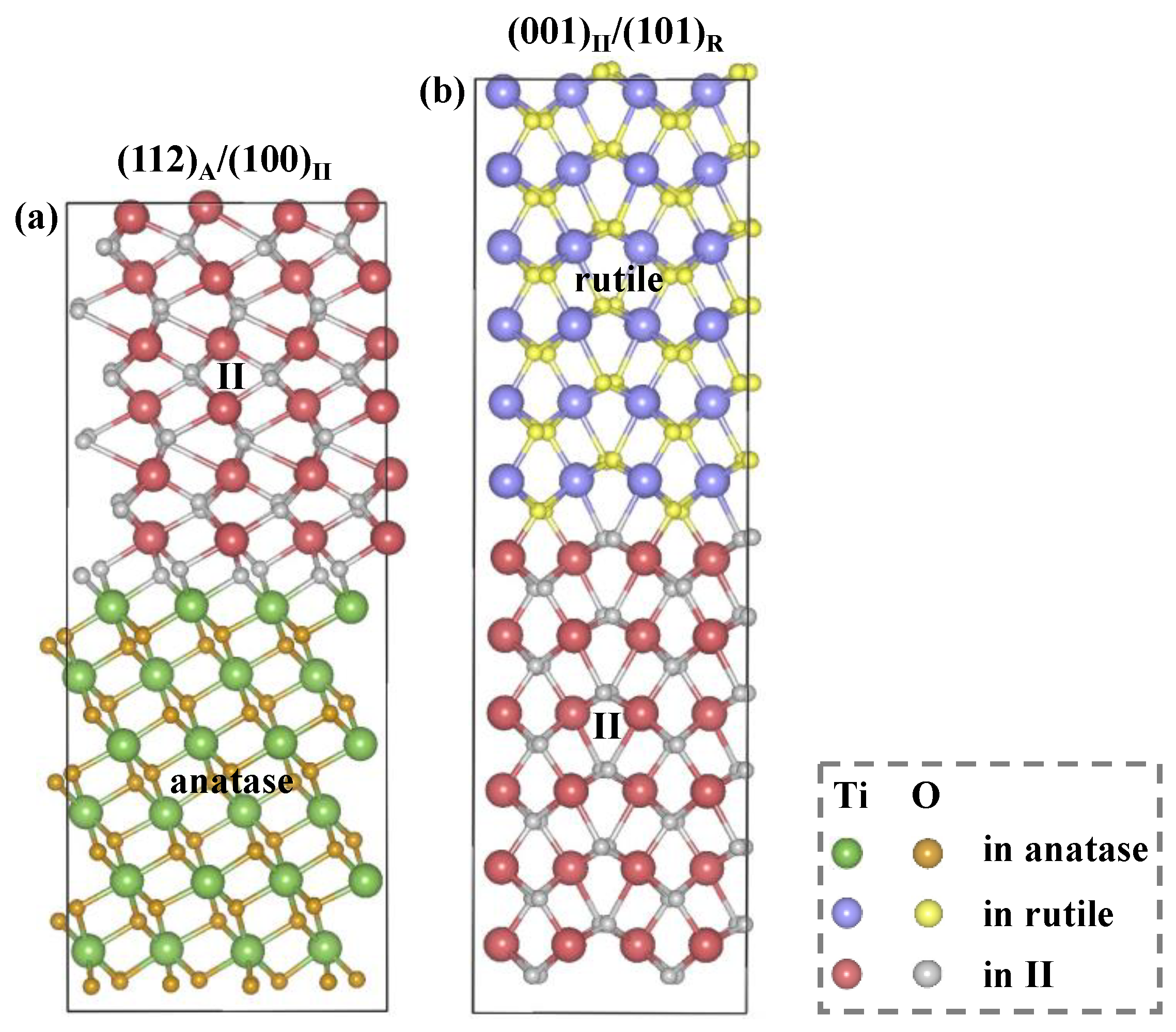
To clarify the charge migration mechanism in anatase/rutile mixed-phase TiO2, a reasonable structural model of the heterophase junction is initially required. According to Liu et al.’s work [22], the three-phase junction model of (112)A/II/(101)R is a nanopin-like structure, i.e., an aperiodic system. Due to the limitations of periodic boundary conditions, this indirect model could not be constructed directly. Therefore, we divided the entire three-phase model ((112)A/II/(101)R) into two separate biphase models, namely (112)A/II and II/(101)R. The indirect three-phase junction model can be obtained by rotating the II/(101)R junction by 90° with respect to the (112)A/II junction and then attaching it to the (112)A/II structure via the intermediate II phase. Based on the structural information from SSW sampling pathways [24,25,26], the intermediate phases in the (112)A/II and II/(101)R models correspond to two different crystal facets, namely the (100) surface (i.e., (112)A/(100)II) and the (001) surface (i.e., (001)II/(101)R).
Prior to the contact, the lattice parameters of anatase (112) and II (100) in the xy dimensions are a = 5.44 Å, b = 5.34 Å and a = 4.93 Å, b = 5.60 Å, respectively (a = 4.63 Å, b = 5.45 Å for rutile (101) and a = 4.59 Å, b = 5.60 Å for II (001)). It can be seen that there is a lattice mismatch between anatase (or rutile) and the intermediate II phases, especially between anatase (112) and II (100) (9.4% and 4.9% along a and b directions, respectively). This large lattice mismatch (>3.0%) will lead to a significant strain and a poor Ti–O match at the interface. Liu et al. suggested that the lattice-misfit strain can be released by reducing the number of atomic layers in the intermediate II phase [22], contributing to a good cation–anion match in the contact region. Therefore, we assume that the lattice parameters of II (100) and II (001) in the biphase models are determined by anatase and rutile phases, respectively, which are consistent with those of anatase (112) and rutile (101). Meanwhile, because II (001) attaches to II (100) by rotating 90°, the lattice of II (001) in the c direction corresponds to that of II (100) in the a direction. Similarly for II (100), its lattice parameter in the c axis is equal to that of II (001) in the a axis.
In addition to the lattice parameters, another important aspect to be taken into account in the construction of interfacial structures is the thickness of TiO2 slabs. We first studied the pure-phase TiO2 of anatase (112) and rutile (101) in vacuum, which were both modeled with 2 × 2 supercells in the xy dimensions. Then, the electrostatic potentials of these two TiO2 surfaces with different atomic layers were calculated (see Tables S1 and S2). By analyzing the convergence of electrostatic potential difference ( V , the difference in average electrostatic potentials between TiO2 and vacuum phases) with the slab thickness (see Figure 1), it is found that the V of both anatase (112) and rutile (101) displays fast convergence at six atomic layers with small oscillations not exceeding 0.02 eV from six- to eight-layer slabs. Therefore, we deemed that the appropriate TiO2 slabs for anatase (112) and rutile (101) are both six atomic layers thick. Regarding the intermediate phases of II (100) and II (001), we evaluated their atomic thickness using the biphase junction models of (112)A/(100)II and (001)II/(101)R. Based on the computed electrostatic potentials (see Tables S3 and S4) and the dependence of V (the difference in average electrostatic potentials between anatase (or rutile) and intermediate II phases) on slab thickness (see Figure 1), a six-layer slab was also chosen for both II (100) and II (001) to ensure the convergence of the TiO2 slab. Following the above analysis, the reasonable heterojunction models of (112)A/(100)II and (001)II/(101)R were established, as illustrated in Figure 2.

2.2. Electronic Properties

Due to the disequilibrium in the electrochemical potentials of electrons, when two semiconductors are in contact, charge transfer will occur at the interface until a unified Fermi level is reached. Work function ( ϕ ) is a key quantity for determining the behavior of charge transfer and can be defined as [27]
ϕ = E v a c E F
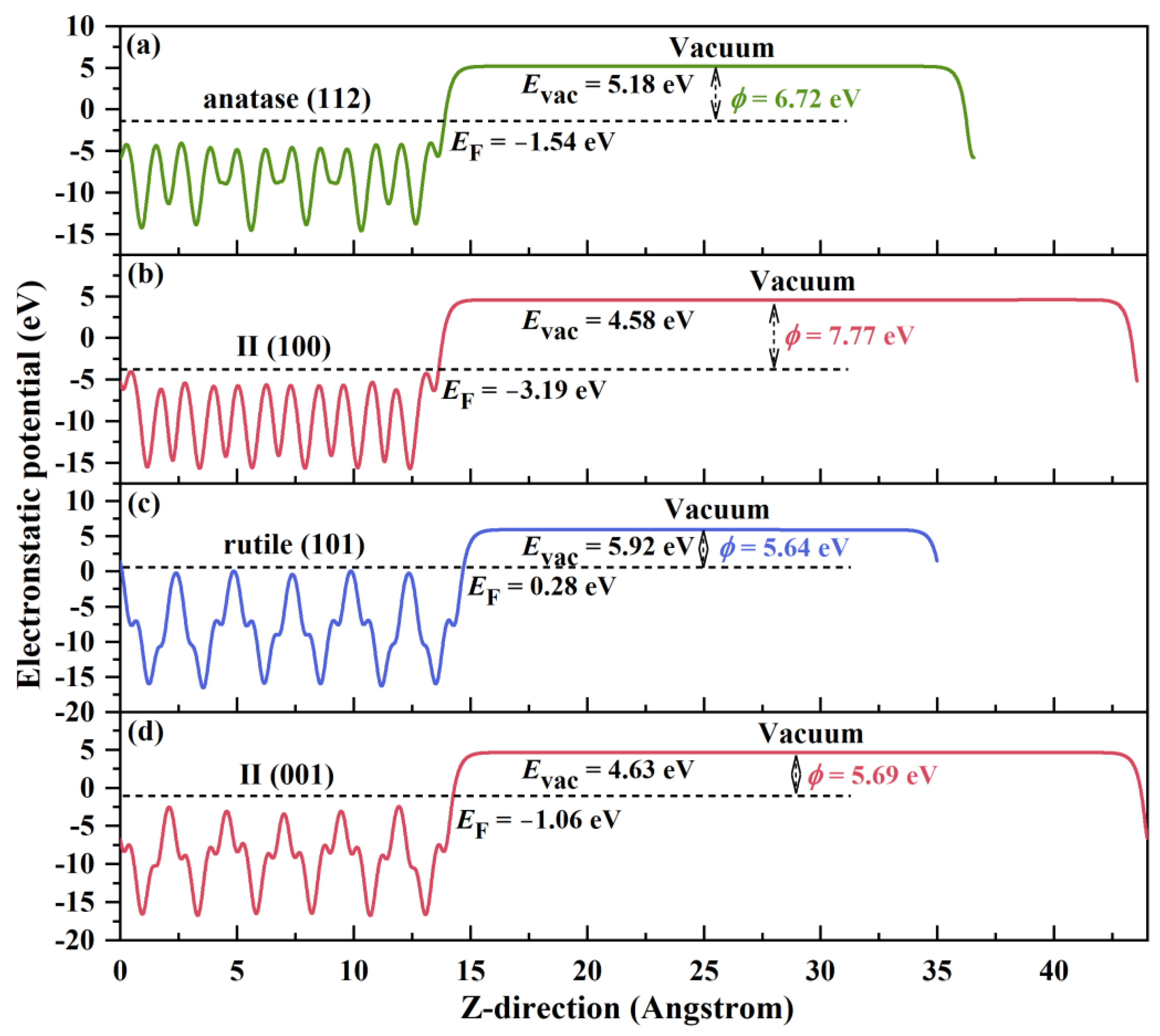
where E v a c and E F are the vacuum level and Fermi level, respectively. Figure 3 displays the profiles of electrostatic potential along the Z direction normal to the TiO2 surfaces. As shown in Figure 3a,b, the work function of II (100) is 7.77 eV, which is higher than that of anatase (112), with 6.72 eV. This indicates that electrons will transfer from anatase (112) to II (100) until the Fermi levels achieve equilibrium. Meanwhile, rutile (101) and II (001) have approximately equivalent work functions (5.64 eV for rutile (101) and 5.69 eV for II (001), see Figure 3c,d). The comparable ϕ values will provide a weak driving force for electron transfer.
To gain a clear understanding of the charge transfer process at the phase junction, the charge density difference ( ρ e ) was further calculated as follows:
ρ e = ρ e i / i i ρ e i ρ e ( i i )
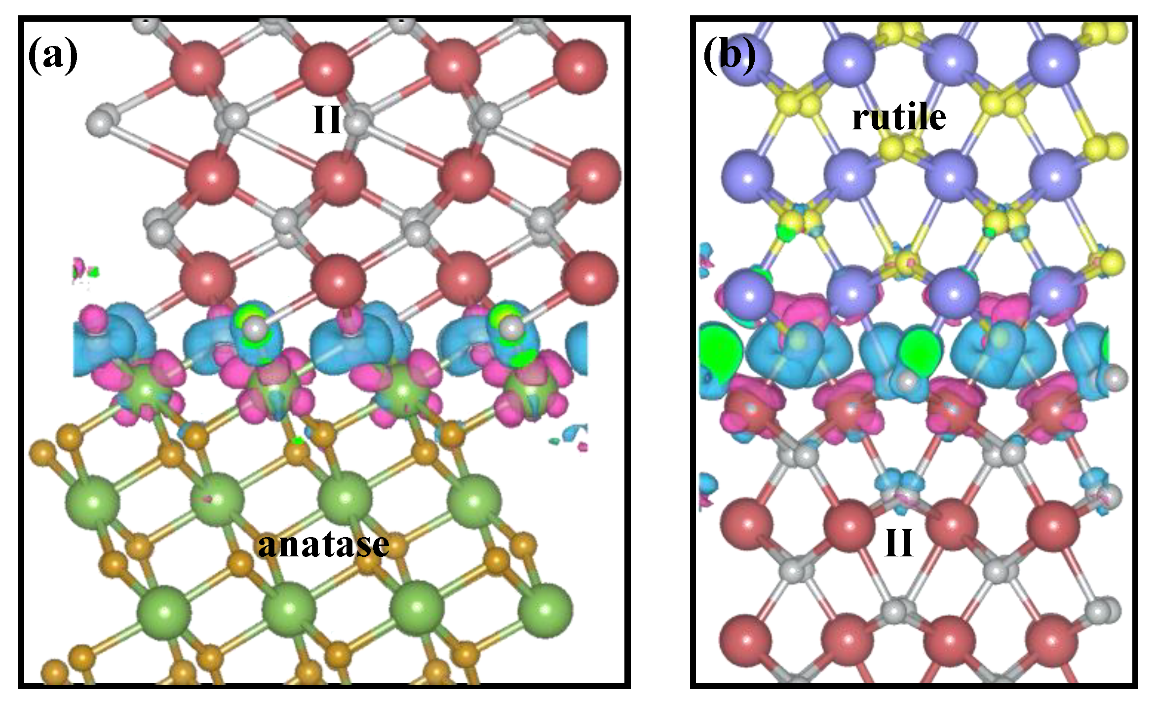
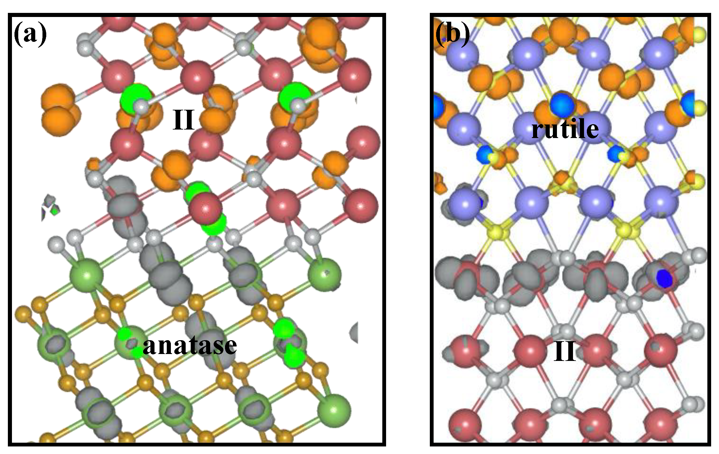
where ρ e i / i i , ρ e i , and ρ e ( i i ) are the electron densities of the i / i i biphase junction, pure phase i, and pure phase ii, respectively. The three-dimensional charge density difference maps for (112)A/(100)II and (001)II/(101)R are plotted in Figure 4. The pink- and blue-colored isosurfaces represent the charge depletion and accumulation regions, respectively. It can clearly be seen that the main charge density changes are localized at the interface. For (112)A/(100)II, the pink isosurfaces appear around the Ti atoms in the anatase phase, while the blue isosurfaces distribute in the O atoms in the intermediate II phase (see Figure 4a). This suggests that there is a charge transfer from anatase (112) to II (100), which is in accordance with the results for the work functions. In the case of (001)II/(101)R, although the charge transfer also occurs between Ti and O atoms, it happens within the respective phase of rutile (101) and II (001) rather than between the two phases (see Figure 4b). This observation provides direct evidence for the aforementioned conclusion that there is less charge transfer across the (001)II/(101)R interface when they are in contact.
The strong charge transfer can cause a distinct charge redistribution at the (112)A/(100)II interface, leading to the creation of an internal built-in electric field and an upward band bending from anatase (112) to II (100) across the phase junction. Upon light illumination, the built-in electric field can provide a direct driving force for the photoelectrons’ transfer from II (100) to anatase (112). However, almost no charge transfer between rutile (101) and II (001) may induce a weak built-in electric field and a negligible band bending. These deductions offer a good explanation for the experimental finding that to achieve good photocatalytic performance for water oxidation, the concentration of the anatase phase in an anatase/rutile heterostructure catalyst should be much higher than that of rutile, i.e., anatase (80%)/rutile (20%) [28,29]. The abundance of the anatase phase is required to form a high concentration of the (112)A/(100)II interface, which is responsible for creating a strong built-in electric field, thereby accelerating the separation and transport of photogenerated charge carriers.

2.3. Charge Migration Mechanism

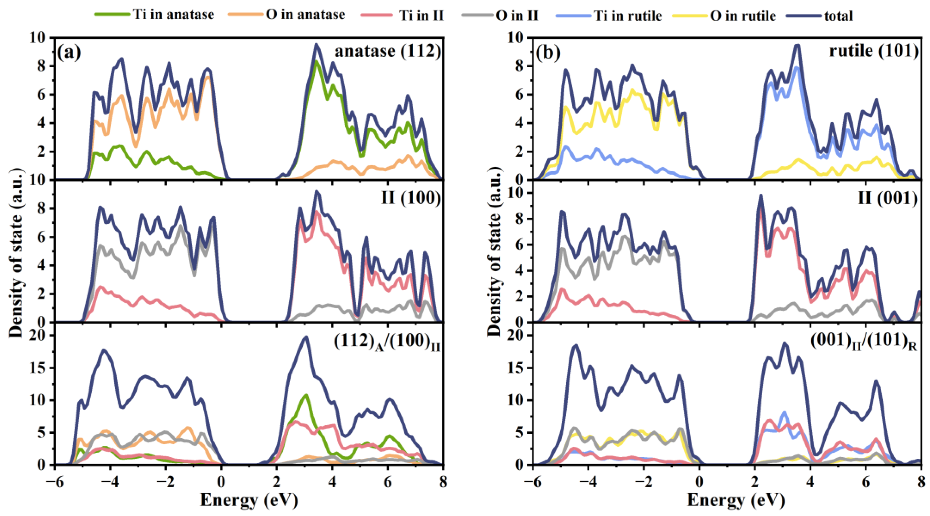
Based on the optimized biphase junction models, the projected density of states (PDOS) and the band edge positions of (112)A/(100)II and (001)II/(101)R with respect to the vacuum level were calculated using the hybrid HSE06 functional, as shown in Figure 5 and Figure 6, respectively. It is noteworthy that for both pure-phase TiO2 (anatase (112), II (100), II (001), and rutile (101)) and mixed-phase TiO2 ((112)A/(100)II and (001)II/(101)R), the CBM positions are primarily derived from the Ti-3d orbitals, while the VBM positions are mainly contributed by the O-2p orbitals. Additionally, the formation of (112)A/(100)II heterojunctions moves the CBM to a lower-energy position, resulting in an obvious reduction in the band gap compared to those of anatase (112) and II (100) (see Figure 5a). Meanwhile, the band gap of the (001)II/(101)R heterojunction remains almost unchanged (see Figure 5b). In Figure 6a, it can be seen that for (112)A/(100)II, the valence and conduction band edges of anatase (112) straddle those of II (100), which is unfavorable for the separation of electron–hole pairs. For (001)II/(101)R, the VBM positions of rutile (101) and II (001) are −6.71 and −7.69 eV, respectively, while the CBM positions are −3.65 and −4.64 eV, respectively. Both the VBM and CBM positions of rutile (101) are obviously higher than those of II (001), leading to a staggered type II heterojunction. Accordingly, the (001)II/(101)R interface is beneficial for electron and hole accumulation on II (001) and rutile (101), respectively. The relative band levels are in agreement with Liu et al.’s results obtained by calculating the energy difference for the electrons and holes [22].
Arranging the band edge positions of (112)A/(100)II and (001)II/(101)R together, we can summarize the overall band alignment of the indirect three-phase junction in anatase/rutile mixed-phase TiO2 (see Figure 6b). This figure shows that the VBM positions of the three phases decrease following the order of rutile > II > anatase. The VBM of rutile is much higher than that of anatase, by 1.24 eV. Consequently, the photogenerated holes can transfer easily from anatase to rutile via the intermediate II phase without a barrier. By contrast, due to the slightly higher conduction band edge of anatase than II, after the photogenerated electrons flow from rutile to II, the electrons may be trapped at the intermediate phase. However, the CBO between the anatase and II phases is only 0.09 eV. Taking into account the computational errors, such a small energy difference can almost be ignored. In addition, the thickness of the intermediate II phase is relatively thin. Thus, the trapped electrons can readily reach saturation and then be driven to the anatase side by the large potential drop between the anatase and rutile phases (0.90 eV). Furthermore, as mentioned above, there is a built-in electric field at the (112)A/(100)II interface directed from anatase (112) to II (100), which is conducive to the photogenerated electrons’ transfer from intermediate II to the anatase phase. To give an intuitive picture about the charge migration direction upon light excitation, the spatial distributions of electrons and holes (gray and orange, respectively) corresponding to the strongest absorptions of (112)A/(100)II (580 nm) and (001)II/(101)R (614 nm) are depicted in Figure 7, which originate from the S0 → S40 and S0 → S41 excitations, respectively. The electron–hole analysis was performed using the Multiwfn software package (version 3.7) [30]. It can clearly be seen that for (112)A/(100)II, the electrons and holes generated upon photoexcitation are mainly localized at the anatase and intermediate II phases, respectively, while for (001)II/(101)R, the photogenerated electrons and holes are distributed in the intermediate II and rutile phases, respectively. Driven by the combined effect of various factors, it can be concluded that in anatase/rutile mixed-phase TiO2, the three-phase junction can prompt the photogenerated electrons to flow to the anatase phase while the holes transfer to the rutile phase, leading to an efficient spatial separation of electron–hole pairs. This charge migration mechanism is consistent with the observation by Li et al. [31]. Experimentally, they showed that the mixed-phase TiO2 exhibiting superior photoelectrochemical water splitting is the TiO2–AR electrode with rutile as the external layer, which possesses an appropriate phase alignment for forward electron migration from rutile to anatase.
In addition to the efficient charge separation and transfer, high-performance semiconductor photocatalysts also require effective solar light utilization. Therefore, the optical absorption spectra of biphase TiO2 ((112)A/(100)II and (001)II/(101)R) were investigated, as illustrated in Figure 8. For comparison, the optical absorption properties for pure-phase TiO2 (anatase (112), II (100), II (001) and rutile (101)) were also included. One can see that the maximum absorption peaks for pure anatase (112) and II (100) are both located at about 500 nm. After the formation of heterojunctions, the (112)A/(100)II heterostructure shows an obvious redshift (about 800 nm) and possesses a larger optical absorption coefficient (see Figure 8a). The redshift is attributed to its reduced band gap (see Figure 5a). The broad and strong optical absorption can promote the photoexcitation of electrons and holes. For (001)II/(101)R, the maximum absorption peak slightly shifts to the red light region and the optical absorption coefficient mildly increases in comparison with those of rutile (101) and II (001) (see Figure 8b). The above findings indicate that the interfacial interaction between anatase (112) and II (100) plays a more significant role in the light absorption than that between rutile (101) and II (001). In addition, in anatase/rutile mixed-phase TiO2, anatase phase should act as a photon adsorption agent, which is in accordance with previous experimental and theoretical studies [22,32].

2.4. CO2 Photoreduction Mechanism

Driven by the spatial charge separation, the photogenerated holes and electrons will preferentially accumulate on rutile and anatase phases, respectively. The photogenerated electrons in the conduction band of anatase can trigger CO2 conversion. Therefore, the CO2 reduction reaction prefers to proceed on the anatase phase. Moreover, (112)A/(100)II heterostructure possesses superior light absorption ability, which is conductive to enhancing its photocatalytic activity. Therefore, the anatase/rutile mixed-phase TiO2 is regarded as a preferable photocatalyst for CO2 conversion. Next, the CO2 reaction processes on the anatase side of (112)A/(100)II heterostructure were systematically explored. In order to reveal the influence of heterojunctions on CO2 reduction, we also took into account the reaction pathways on pure-phase anatase for comparison.
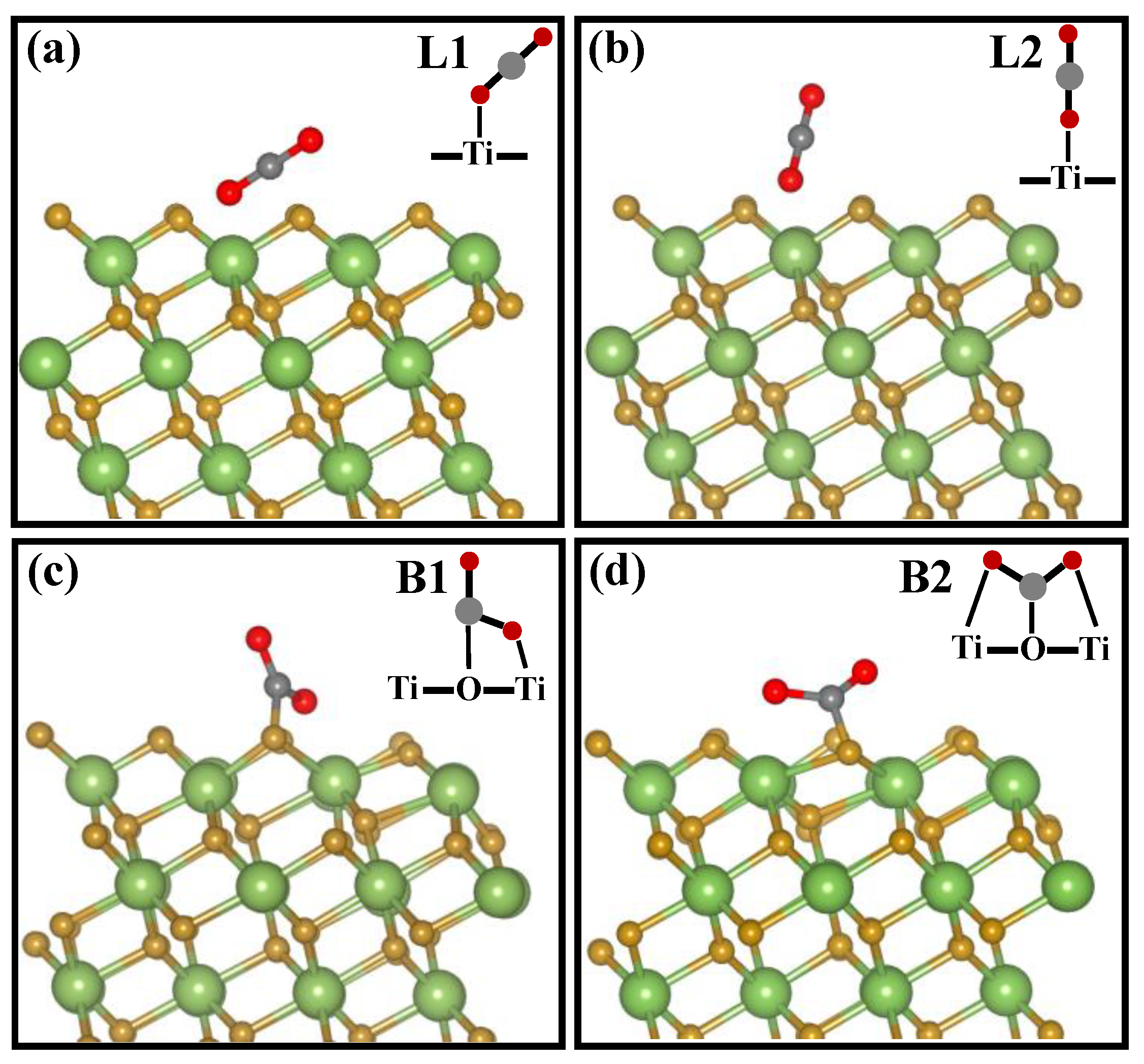
The adsorption of CO2 on the catalyst surface is the initial and most vital step in the CO2 reduction reaction [7]. The CO2 adsorption configurations have a significant influence on the selectivity of catalytic reactions in the following steps [33,34]. Therefore, our study started by investigating the adsorption behaviors of CO2 on the anatase surface. In this simulation, four possible configurations for the CO2 adsorption were explored and the corresponding optimized geometries are shown in Figure 9. According to the calculated adsorption energies ( E a d = E T i O 2 / C O 2 E T i O 2 E ( C O 2 ) ) (see Table 1), it is found that in all adsorption configurations, the Ead,A/II values are more positive than Ead,A, indicating a weaker adsorption capacity of CO2 adsorbed on the (112)A/(100)II heterostructure compared to that on the pure-phase anatase surface. This may be attributed to the fact that the formation of a (112)A/(100)II heterostructure can induce the charge transfer between anatase (112) and II (100) surfaces. The charge redistribution may break the original stability of the anatase (112) surface and thus cause a slight local deformation on the anatase surface, which is unfavorable for CO2 adsorption on the (112)A/(100)II heterostructure. In addition, the most stable adsorption configuration of CO2 on both pure-phase anatase and the (112)A/(100)II heterojunction is a nearly linear configuration (L1), slightly tilted relative to the surface normal through the interaction of the O atom in CO2 with surface five-fold-coordinated Ti5c (d(Ti5cO) = 2.62 and 2.71 Å, respectively) and the C atom in CO2 with surface-bridging O2c (d(O2cC) = 2.70 and 2.78 Å, respectively). The metastable structure also displays a linear configuration (L2), in which the CO2 molecule is nearly vertically adsorbed on the top of surface Ti5c atoms through relatively weak interactions with an adsorption energy of −0.02 and 0.21 eV, respectively. In bidentate carbonate (B1, one side of CO2 laying along the Ti5c–O2c bond) and bridged carbonate (B2, two O atoms in CO2 bridging two surface Ti5c and the C atom in CO2 pointing downward) adsorption configurations, the CO2 molecules are largely deformed with respect to the linear shape and exhibit bent structures. Both of these configurations are unstable and the energy of the B2 structure is even higher than that of B1 by 0.53 and 0.30 eV, respectively. The stability order of the adsorption structures, L1 > L2 > B1 > B2, is similar to the CO2 adsorption on anatase (101) surfaces [35,36,37]. Meanwhile, on anatase (001) [33] and rutile (001) surfaces [38], the most stable CO2 adsorption structure displays a bent configuration, suggesting that the CO2 adsorption behavior is related to both the adsorbed crystal phases and the crystal facets. Based on the above analyses, the L1 configuration is chosen for the following mechanism study of CO2 photoreduction on both pure-phase anatase and a (112)A/(100)II heterostructure.
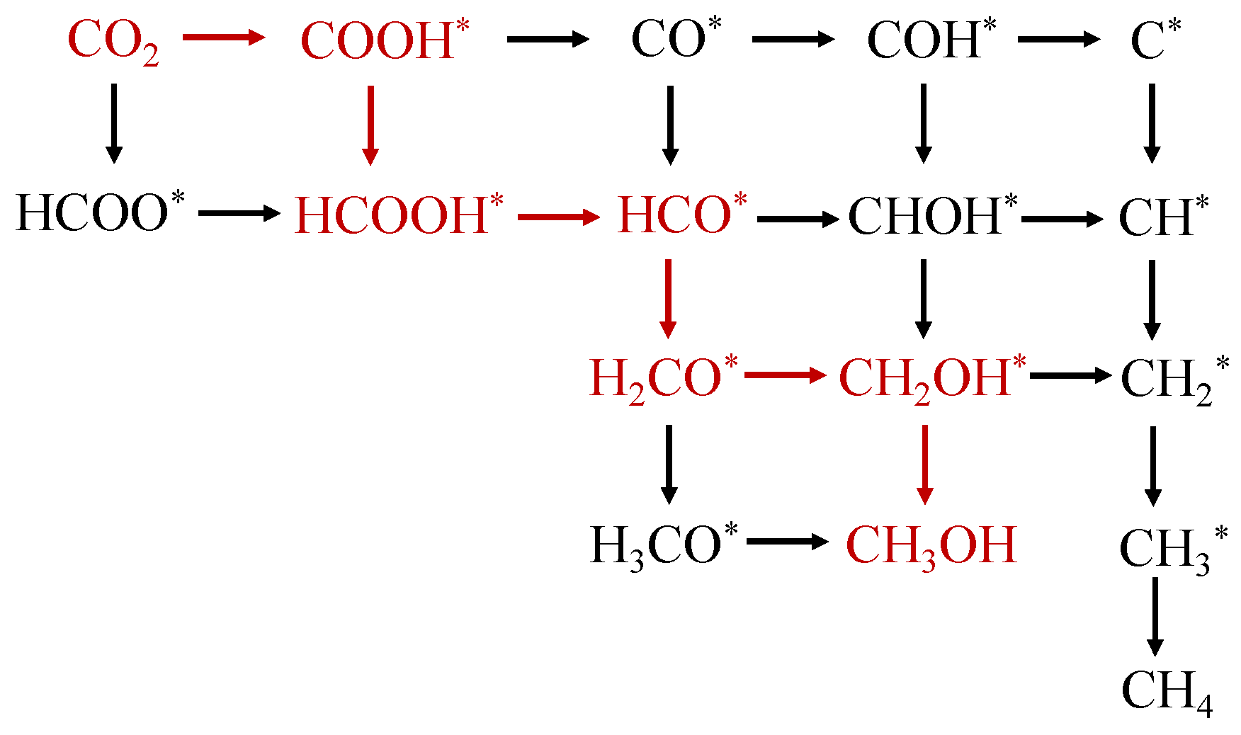
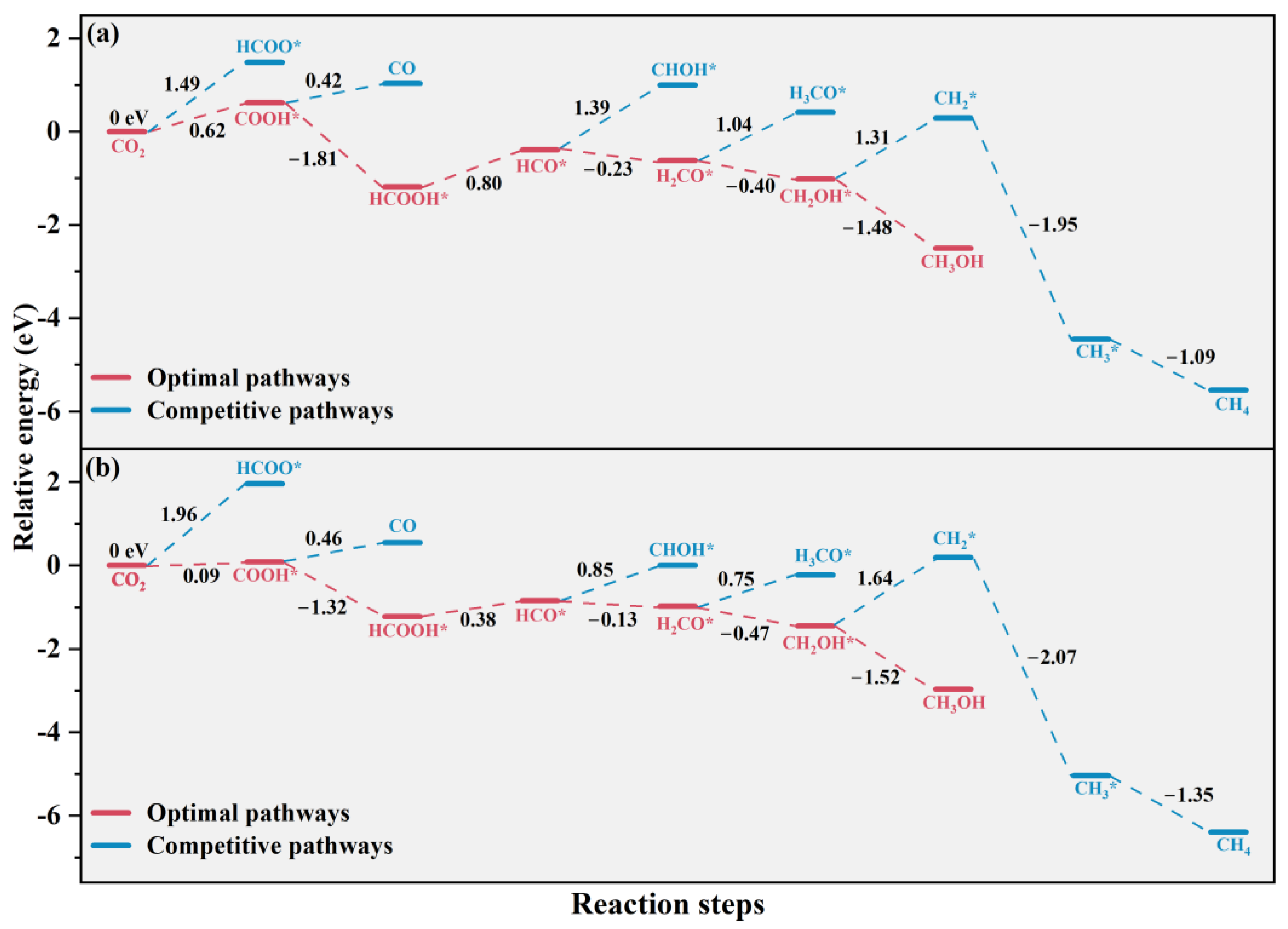
Possible reaction pathways and intermediates of CO2 reduction are listed in Scheme 1 and the potential-energy-change profiles of various possible reaction pathways are displayed in Figure 10. Our investigations show that for the first hydrogenation step on pure-phase anatase, the reaction energy of the formation of COOH* by connecting the H atom to the O atom of CO2 is 0.62 eV, which is more thermodynamically favorable by 0.87 eV than the generation of HCOO* through the H atom’s addition to the C atom (see Figure 10a). This is mainly because due to the higher electronegativity of the O atom, as the C and O atoms of CO2 are positively and negatively charged, respectively. Hence, the O atom of CO2 is more easily hydrogenated to COOH*. COOH* subsequently undergoes hydrogenation to HCOOH or dehydroxylation to CO. The acquisition of HCOOH is an exothermic reaction with an energy decrease of −1.81 eV, whereas the transformation to CO is an endothermic process (0.42 eV). Therefore, CO2 is more likely to undergo a two-step hydrogenation mechanism to HCOOH. In addition, the adsorption energy for HCOOH and CO are −1.57 and −0.33 eV, respectively. This suggests that the interaction between HCOOH and anatase is stronger than that of CO, which further confirms that HCOOH is the preferential intermediate product. Then, HCOOH* is hydrogenated and dehydrated to form HCO*, and this step is considered to be the rate-limiting step with the highest energy barrier of 0.80 eV. The next step of HCO* hydrogenation contains two possible pathways—one to H2CO* and the other one to CHOH*. The production of H2CO* has an exothermic reaction energy of −0.23 eV, while the formation of CHOH* is an endothermic process with a distinct energy increase of 1.39 eV, indicating that the generation of H2CO* is more favorable than CHOH*. Subsequently, H2CO is more easily reduced to CH2OH* intermediate (−0.40 eV), rather than undergoing hydrogenation to form CH3O* (1.04 eV). In the following step, there are considerable differences in the reaction energies for the formation of CH3OH (−1.48 eV) and CH2* (1.31 eV). The significantly negative energy barrier implies that CH2OH*’s reduction to CH3OH is more competitive relative to CH2*. In addition, it is noted that CH2OH* → CH2* is the rate-limiting step for CH4 formation, and its corresponding energy barrier (1.31 eV) is much higher than the rate-limiting energy for CH3OH generation (HCOOH* → HCO* with 0.80 eV). Therefore, the final product is more likely to be CH3OH. In brief, the optimal route of CO2 reduction on pure-phase anatase is CO2 → COOH* → HCOOH* → HCO* → H2CO* → CH2OH* → CH3OH, which is similar to the reaction mechanism of CO2 reduction on g-C3N4-based photocatalysts [39,40].
Figure 10b presents the potential energy diagram of CO2 reduction reaction pathways on the (112)A/(100)II heterostructure. It can be seen that the reaction pathways of CO2’s transformation to CO, CH3OH, and CH4 on the (112)A/(100)II heterostructure are the same as those on pure-phase anatase, but the corresponding reaction energy for each step is quite different. On the (112)A/(100)II heterostructure, the calculated reaction energy of the initial step of CO2’s hydrogenation to the COOH* intermediate is 0.09 eV, which is much smaller than that on pure-phase anatase, at 0.62 eV, indicating that the (112)A/(100)II heterostructure is more conductive to the formation of COOH* through a barrierless pathway. This is mainly because when anatase (112) and II (100) surfaces are in contact, there will be charge transfer between the two phases. The charge rearrangement may induce more negative charges around the O atoms of CO2 on the (112)A/(100)II heterostructure (−0.19 and −0.27 e) compared to those on pure-phase anatase (−0.14 and −0.20 e). Consequently, the H atom is preferably bound to the O atom of CO2 on the (112)A/(100)II heterostructure to generate the COOH* intermediate. In addition, although the rate-limiting step of generating CH3OH on the (112)A/(100)II heterostructure is also the hydrogenation and dehydration of HCOOH* to HCO*, it possesses a lower energy barrier than the pure-phase anatase by 0.42 eV. Moreover, the reaction energy of CH2OH*’s reduction to CH2* on the (112)A/(100)II heterostructure is 1.64 eV, much higher than that on pure-phase anatase (1.31 eV), which suggests that the selectivity of CO2 reduction to form CH3OH might be enhanced on mixed-phase TiO2. In summary, the (112)A/(100)II heterostructure is more favorable for the generation of CH3OH compared to pure-phase anatase. It is known that commercial P25 is also a mixed-phase TiO2. However, many experimental studies have shown that the P25 photocatalyst exhibited excellent photoreduction activity in reducing CO2 into CH4 [41,42,43], which is different from the main product generated by our constructed anatase/rutile heterostructure model. This distinction may originate from the differences in the exposed surface for the CO2 reaction process, proceeding on the anatase (112) surface in our model and the anatase (101) surface in P25 [41,42,43].

3. Methods

3.1. Calculations of Band Edges

In the heterojunction model, the band information that we could directly obtain was the valence band maximum (VBM) and the conduction band minimum (CBM) positions of the overall system. Then, the valence band offset (VBO) and conduction band offset (CBO) at the mixed-phase junctions were calculated to evaluate how the remaining two band edges were shifted relative to the VBM and CBM. Based on the viewpoint proposed by Ceder et al. that the difference between energy level and Hartree potential remains unchanged everywhere in space [44], the valence band offset value ( E V B O ) can be computed as
E V B O = H O M O i b u l k V i b u l k H O M O i i b u l k V i i b u l k + ( V i i n t V i i i n t )
where i and ii stand for the semiconductors of phase i and phase ii, respectively. H O M O s c b u l k is the highest occupied molecular orbital (HOMO) energy of the bulk semiconductor. V s c b u l k is the electrostatic potential of the bulk semiconductor. Under the periodic boundary condition (PBC), the V s c b u l k value is zero. V s c i n t is the averaged electrostatic potential in the bulk-like region of the heterojunction interface for a semiconductor, which is obtained by nanosmoothing the original electrostatic potential profile with the MACROAVE code [45]. E V B O > 0 suggests that the photogenerated holes tend to flow from phase ii to phase i.
In the same way, the conduction band offset value ( E C B O ) is given by
E C B O = L U M O i b u l k V i b u l k L U M O i i b u l k V i i b u l k + ( V i i n t V i i i n t )
where L U M O s c b u l k is the lowest unoccupied molecular orbital (LUMO) energy of the bulk semiconductor. E C B O > 0 indicates that the photogenerated electrons are likely to transfer from phase i to phase ii.

3.2. Computational Setup

All density functional theory (DFT) simulations were performed using the freely available program package CP2K/Quickstep [46]. The Perdew–Burke–Ernzerhof (PBE) functional [47] was employed for ab initio calculations. The basis sets for valence electrons were double-ζ basis functions with one set of polarization functions (DZVP) [48]. The core electrons were represented using analytic Goedecker–Teter–Hutter (GTH) pseudopotentials [49]. The dispersion correction of the Grimme method D3 [50] was adopted to describe the van der Waals interactions. For geometry optimizations, the wave function optimization was carried out using an orbital transformation minimizer, which can give the optimal convergence control [51]. Meanwhile, for absorption spectra calculations, the matrix diagonalization method was applied to obtain the wave function information of unoccupied molecular orbitals for data analysis. The convergence criterion for wave function optimization was set at a maximum electronic gradient of 3 × 10⁻⁷ a.u. and the plane wave cutoff for the electron density expansion was 400 Ry. It is known that when employing the pure generalized gradient approximation (GGA) functional to estimate the solid electronic structures, there is a delocalization error leading to an underestimation of the band gap. Therefore, to more accurately describe the alignment of electronic energy levels across the heterojunction interface, the band edge positions were computed using the Heyd–Scuseria–Ernzerhof (HSE06) screened hybrid functional [52,53] based on the structures from the PBE functional calculations.

4. Conclusions

In this work, the band edges of three-phase junctions in the anatase/rutile mixed-phase TiO2 were successfully determined and the mechanism of charge separation and transport across the anatase/rutile interface was revealed based on ab initio simulations. Our results show that the VBM positions decrease in the order of rutile > II > anatase, facilitating the holes’ transfer from anatase to rutile phases under sunlight irradiation. Meanwhile, the CBM position of anatase is slightly higher than that of intermediate II phase, and thus the II will act as an electron trapping site and impede the electrons’ flow from rutile to anatase. However, the potential drop across the anatase/rutile interface is so large that it can provide a relatively high driving force for the photoelectrons’ migration to anatase via the very thin layer of II. Moreover, the work function of II is higher than that of anatase, leading to the formation of a built-in electric field and an upward band bending from anatase to II, which is also favorable for the electrons’ accumulation on the anatase phase. Briefly, electron transfer from rutile to anatase is energetically permitted, as indicated experimentally [17,31]. In addition, it is found that after the construction of the (112)A/(100)II heterostructure, its optical absorption capacity is significantly enhanced compared to the pure-phase anatase. The effective utilization of solar light is conductive to promoting the photocatalytic activity.
Simultaneously, the CO2 photoreduction mechanism on an anatase (112) surface was systematically investigated. It is confirmed that the most stable CO2 adsorption configuration is a nearly linear configuration (L1), slightly tilted with respect to the surface normal, which is similar to the adsorption behavior on an anatase (101) surface [35]. The calculated potential energies suggest that on both pure-phase anatase and the (112)A/(100)II heterostructure, CH3OH is more liable to be the final product and the corresponding optimal route is CO2 → COOH* → HCOOH* → HCO* → H2CO* → CH2OH* → CH3OH. During the whole reaction process, the rate-limiting step is the hydrogenation and dehydration of HCOOH to HCO*. The rate-limiting energy on the (112)A/(100)II heterostructure is obviously lower than that on pure-phase anatase, and the first hydrogenation step of CO2 to COOH* on the (112)A/(100)II heterostructure is thermodynamically spontaneous with a barrierless pathway, demonstrating that anatase/rutile mixed-phase TiO2 is an excellent photocatalyst for CO2 reduction.

Supplementary Materials

The following supporting information can be downloaded at: https://www.mdpi.com/article/10.3390/molecules29174105/s1, Table S1: The average electrostatic potentials of the anatase phase ( V a n a t a s e , eV), vacuum phase ( V v a c , eV), and the electrostatic potential difference ( V , eV) for the anatase (112) surface; Table S2: The average electrostatic potentials of the rutile phase ( V r u t i l e , eV), vacuum phase ( V v a c , eV), and the electrostatic potential difference ( V , eV) for the rutile (101) surface; Table S3: The average electrostatic potentials of the anatase phase ( V a n a t a s e , eV), intermediate II phase ( V I I , eV), and the electrostatic potential difference ( V , eV) for the (112)A/(100)II heterojunction; Table S4: The average electrostatic potentials of the intermediate II phase ( V I I , eV), rutile phase ( V r u t i l e , eV), and the electrostatic potential difference ( V , eV) for the (001)II/(101)R heterojunction.

Author Contributions

J.L.: conceptualization, methodology, investigation, validation, formal analysis, writing—original draft; S.W. and Y.D.: data curation; Y.Z.: writing—review and editing, supervision, funding acquisition; L.W.: project administration, resources, writing—review and editing. All authors have read and agreed to the published version of the manuscript.

Funding

The project was supported by the National Natural Science Foundation of China (Grant Nos. 22103051 and 22301172), the Natural Science Foundation of Henan for Excellent Young Scholars (Grant No. 242300421140) and the Program for Science & Technology Innovative Research Team in University of Henan Province (Grant No. 20IRTSTHN007).

Institutional Review Board Statement

Not applicable.

Informed Consent Statement

Not applicable.

Data Availability Statement

The data presented in this study are available in this article and the Supplementary Materials.

Acknowledgments

We gratefully acknowledge Beijing super cloud computing center for providing computer facilities and the research start-up foundation of Shangqiu Normal University.

Conflicts of Interest

The authors declare no conflicts of interest.

References

  1. Khan, M.D.; Fareed, I.; ul Hassan Farooq, M.; Akram, M.; ur Rehman, S.; Ali, Z.; Tariq, Z.; Irshad, M.; Li, C.; Butt, F.K. Methodologies for enriched photocatalytic CO2 reduction: An overview. Int. J. Environ. Sci. Technol. 2024, 21, 3489–35269. [Google Scholar] [CrossRef]
  2. Li, X.; Xiong, J.; Tang, Z.; He, W.; Wang, Y.; Wang, X.; Zhao, Z.; Wei, Y. Recent progress in metal oxide-based photocatalysts for CO2 reduction to solar fuels: A Review. Molecules 2023, 28, 1653. [Google Scholar] [CrossRef] [PubMed]
  3. Ran, J.; Jaroniec, M.; Qiao, S.Z. Cocatalysts in semiconductor-based photocatalytic CO2 reduction: Achievements, challenges, and opportunities. Adv. Mater. 2018, 30, 1704649. [Google Scholar] [CrossRef]
  4. Rehman, Z.U.; Bilal, M.; Hou, J.; Butt, F.K.; Ahmad, J.; Ali, S.; Hussain, A. Photocatalytic CO2 reduction using TiO2-based photocatalysts and TiO2 Z-scheme heterojunction composites: A review. Molecules 2022, 27, 2069. [Google Scholar] [CrossRef]
  5. Kreft, S.; Wei, D.; Junge, H.; Beller, M. Recent advances on TiO2-based photocatalytic CO2 reduction. EnergyChem 2020, 2, 100044. [Google Scholar] [CrossRef]
  6. Schneider, J.; Matsuoka, M.; Takeuchi, M.; Zhang, J.; Horiuchi, Y.; Anpo, M.; Bahnemann, D.W. Understanding TiO2 photocatalysis: Mechanisms and materials. Chem. Rev. 2014, 114, 9919–9986. [Google Scholar] [CrossRef]
  7. Gong, E.; Ali, S.; Hiragond, C.B.; Kim, H.S.; Powar, N.S.; Kim, D.; Kim, H.; In, S. Solar fuels: Research and development strategies to accelerate photocatalytic CO2 conversion into hydrocarbon fuels. Energy Environ. Sci. 2021, 15, 880–937. [Google Scholar] [CrossRef]
  8. Liu, J.Y.; Gong, X.Q.; Alexandrova, A.N. Mechanism of CO2 photocatalytic reduction to methane and methanol on defected anatase TiO2 (101): A density functional theory study. J. Phys. Chem. C 2019, 123, 3505–3511. [Google Scholar] [CrossRef]
  9. Umezawa, N.; Kristoffersen, H.H.; Vilhelmsen, L.B.; Hammer, B. Reduction of CO2 with water on Pt-loaded rutile TiO2(110) modeled with density functional theory. J. Phys. Chem. C 2016, 120, 9160–9164. [Google Scholar] [CrossRef]
  10. Xu, Q.; Yu, J.; Zhang, J.; Zhang, J.; Liu, G. Cubic anatase TiO2 nanocrystals with enhanced photocatalytic CO2 reduction activity. Chem. Commun. 2015, 51, 7950–7953. [Google Scholar] [CrossRef]
  11. Du, J.; Shi, H.; Wu, J.; Li, K.; Song, C. Interface and defect engineering of a hollow TiO2@ ZnIn2S4 heterojunction for highly enhanced CO2 photoreduction activity. ACS Sustain. Chem. Eng. 2023, 11, 2531–2540. [Google Scholar] [CrossRef]
  12. Hwang, H.M.; Oh, S.; Shim, J.H.; Kim, Y.M.; Kim, A.; Kim, D.; Kim, J.; Bak, S.; Cho, Y.; Bui, V.Q.; et al. Phase-selective disordered anatase/ordered rutile interface system for visible-light-driven, metal-free CO2 reduction. ACS Appl. Mater. Interfaces 2019, 11, 35693–35701. [Google Scholar] [CrossRef]
  13. Xiong, J.; Zhang, M.; Cheng, G. Facile polyol-triggered anatase–rutile heterophase TiO2-x nanoparticles for enhancing photocatalytic CO2 reduction. J. Colloid Interface Sci. 2020, 579, 872–877. [Google Scholar] [CrossRef]
  14. Qu, J.; He, J.; Li, H.; Jiang, Q.; Li, M.; Kong, Q.; Shi, M.; Li, R.; Li, C. Unraveling the role of interface in photogenerated charge separation at the anatase/rutile heterophase junction. J. Phys. Chem. C 2023, 127, 768–775. [Google Scholar] [CrossRef]
  15. Komaguchi, K.; Nakano, H.; Araki, A.; Harima, Y. Photoinduced electron transfer from anatase to rutile in partially reduced TiO2 (P-25) nanoparticles: An ESR study. Chem. Phys. Lett. 2006, 428, 338–342. [Google Scholar] [CrossRef]
  16. Kawahara, T.; Konishi, Y.; Tada, H.; Tohge, N.; Nishii, J.; Ito, S. A patterned TiO2(anatase)/TiO2(rutile) bilayer-type photocatalyst: Effect of the anatase/rutile junction on the photocatalytic activity. Angew. Chem. 2002, 114, 2935–2937. [Google Scholar] [CrossRef]
  17. Gao, Y.; Zhu, J.; An, H.; Yan, P.; Huang, B.; Chen, R.; Fan, F.; Li, C. Directly probing charge separation at interface of TiO2 phase junction. J. Phys. Chem. Lett. 2017, 8, 1419–1423. [Google Scholar] [CrossRef]
  18. Deskins, N.A.; Kerisit, S.; Rosso, K.M.; Dupuis, M. Molecular dynamics characterization of rutile-anatase interfaces. J. Phys. Chem. C 2007, 111, 9290–9298. [Google Scholar] [CrossRef]
  19. Xia, T.; Li, N.; Zhang, Y.; Kruger, M.B.; Murowchick, J.; Selloni, A.; Chen, X. Directional heat dissipation across the interface in anatase-rutile nanocomposites. ACS Appl. Mater. Interfaces 2013, 5, 9883–9890. [Google Scholar] [CrossRef]
  20. Kullgren, J.; Huy, H.A.; Aradi, B.; Frauenheim, T.; Deák, P. Theoretical study of charge separation at the rutile-anatase interface. Phys. Status Solidi Rapid Res. Lett. 2014, 8, 566–570. [Google Scholar] [CrossRef]
  21. Ju, M.G.; Sun, G.; Wang, J.; Meng, Q.; Liang, W. Origin of high photocatalytic properties in the mixed-phase TiO2: A first-principles theoretical study. ACS Appl. Mater. Interfaces 2014, 6, 12885–12892. [Google Scholar] [CrossRef] [PubMed]
  22. Zhao, W.N.; Zhu, S.C.; Li, Y.F.; Liu, Z.P. Three-phase junction for modulating electron-hole migration in anatase-rutile photocatalysts. Chem. Sci. 2015, 6, 3483–3494. [Google Scholar] [CrossRef] [PubMed]
  23. Hosono, E.; Fujihara, S.; Imai, H.; Honma, I.; Masaki, I.; Zhou, H. One-step synthesis of nano—Micro chestnut TiO2 with rutile nanopins on the microanatase octahedron. ACS Nano 2007, 1, 273–278. [Google Scholar] [CrossRef]
  24. Shang, C.; Zhang, X.J.; Liu, Z.P. Stochastic surface walking method for crystal structure and phase transition pathway prediction. Phys. Chem. Chem. Phys. 2014, 16, 17845–17856. [Google Scholar] [CrossRef]
  25. Zhu, S.C.; Xie, S.H.; Liu, Z.P. Design and observation of biphase TiO2 crystal with perfect junction. J. Phys. Chem. Lett. 2014, 5, 3162–3168. [Google Scholar] [CrossRef]
  26. Shang, C.; Liu, Z.P. Stochastic surface walking method for structure prediction and pathway searching. J. Chem. Theory Comput. 2013, 9, 1838–1845. [Google Scholar] [CrossRef]
  27. Kahn, A. Fermi Level, Work function and vacuum level. Mater. Horizons 2016, 3, 7–10. [Google Scholar] [CrossRef]
  28. Lopez, T.; Sanchez, E.; Bosch, P.; Meas, Y.; Gomez, R. FTIR and UV-Vis (diffuse reflectance) spectroscopic characterization of TiO2 sol-gel. Mater. Chem. Phys. 1992, 32, 141–152. [Google Scholar] [CrossRef]
  29. Sanchez, E.; Lopez, T. Effect of the preparation method on the band gap of titania and platinum-titania sol-gel materials. Mater. Lett. 1995, 25, 271–275. [Google Scholar] [CrossRef]
  30. Lu, T.; Chen, F. Multiwfn: A multifunctional wavefunction analyzer. J. Comput. Chem. 2012, 33, 580–592. [Google Scholar] [CrossRef] [PubMed]
  31. Li, A.; Wang, Z.; Yin, H.; Wang, S.; Yan, P.; Huang, B.; Wang, X.; Li, R.; Zong, X.; Han, H.; et al. Understanding the anatase-rutile phase junction in charge separation and transfer in a TiO2 electrode for photoelectrochemical water splitting. Chem. Sci. 2016, 7, 6076–6082. [Google Scholar] [CrossRef]
  32. Bickley, R.I.; Gonzalez-Carreno, T.; Lees, J.S.; Palmisano, L.; Tilley, R.J.D. A structural investigation of titanium dioxide photocatalysts. J. Solid State Chem. 1991, 92, 178–190. [Google Scholar] [CrossRef]
  33. Ma, S.; Song, W.; Liu, B.; Zhong, W.; Deng, J.; Zheng, H.; Liu, J.; Gong, X.Q.; Zhao, Z. Facet-dependent photocatalytic performance of TiO2: A DFT study. Appl. Catal. B Environ. 2016, 198, 1–8. [Google Scholar] [CrossRef]
  34. He, H.; Zapol, P.; Curtiss, L.A. Computational screening of dopants for photocatalytic two-electron reduction of CO2 on anatase (101) surfaces. Energy Environ. Sci. 2012, 5, 6196–6205. [Google Scholar] [CrossRef]
  35. Mino, L.; Spoto, G.; Ferrari, A.M. CO2 capture by TiO2 anatase surfaces: A combined DFT and FTIR study. J. Phys. Chem. C 2014, 118, 25016–25026. [Google Scholar] [CrossRef]
  36. He, H.; Zapol, P.; Curtiss, L.A. A theoretical study of CO2 anions on anatase (101) surface. J. Phys. Chem. C 2010, 114, 21474–21481. [Google Scholar] [CrossRef]
  37. Sorescu, D.C.; Al-Saidi, W.A.; Jordan, K.D. CO2 adsorption on TiO2(101) anatase: A dispersion-corrected density functional theory study. J. Chem. Phys. 2011, 135, 124701. [Google Scholar] [CrossRef] [PubMed]
  38. Kovačič, Ž.; Likozar, B.; Huš, M. Electronic properties of rutile and anatase TiO2 and their effect on CO2 adsorption: A comparison of first principle approaches. Fuel 2022, 328, 125322. [Google Scholar] [CrossRef]
  39. Fei, X.; Tan, H.; Cheng, B.; Zhu, B.; Zhang, L. 2D/2D black phosphorus/G-C3N4 S-scheme heterojunction photocatalysts for CO2 reduction investigated using DFT calculations. Acta Phys. Chim. Sin. 2021, 37, 2010027. [Google Scholar]
  40. Fei, X.; Zhang, L.; Yu, J.; Zhu, B. DFT study on regulating the electronic structure and CO2 reduction reaction in BiOBr/sulphur-doped G-C3N4 S-scheme heterojunctions. Front. Nanotechnol. 2021, 3, 698351. [Google Scholar] [CrossRef]
  41. Ye, M.; Wang, X.; Liu, E.; Ye, J.; Wang, D. Boosting the photocatalytic activity of P25 for carbon dioxide reduction by using a surface-alkalinized titanium carbide MXene as cocatalyst. ChemSusChem 2018, 11, 1606–1611. [Google Scholar] [CrossRef] [PubMed]
  42. Collado, L.; García-Tecedor, M.; Gomez-Mendoza, M.; Pizarro, A.H.; Oropeza, F.E.; Liras, M.; de la Peña O’Shea, V.A. Unravelling charge dynamic effects in photocatalytic CO2 reduction over TiO2: Anatase vs P25. Catal. Today 2023, 423, 114279. [Google Scholar] [CrossRef]
  43. Hiragond, C.B.; Biswas, S.; Powar, N.S.; Lee, J.; Gong, E.; Kim, H.; Kim, H.S.; Jung, J.W.; Cho, C.H.; Wong, B.M.; et al. Surface-modified Ag@Ru-P25 for photocatalytic CO2 conversion with high selectivity over CH4 formation at the solid–gas interface. Carbon Energy 2024, 6, e386. [Google Scholar] [CrossRef]
  44. Wu, Y.; Chan, M.K.Y.; Ceder, G. Prediction of semiconductor band edge positions in aqueous environments from first principles. Phys. Rev. B Condens. Matter Mater. Phys. 2011, 83, 235301. [Google Scholar] [CrossRef]
  45. Junquera, J.; Cohen, M.H.; Rabe, K.M. Nanoscale smoothing and the analysis of interfacial charge and dipolar densities. J. Phys. Condens. Matter 2007, 19, 213203. [Google Scholar] [CrossRef]
  46. Vandevondele, J.; Krack, M.; Mohamed, F.; Parrinello, M.; Chassaing, T.; Hutter, J. Quickstep: Fast and accurate density functional calculations using a mixed Gaussian and plane waves approach. Comput. Phys. Commun. 2005, 167, 103–128. [Google Scholar] [CrossRef]
  47. Perdew, J.P.; Burke, K.; Ernzerhof, M. Generalized gradient approximation made simple. Phys. Rev. Lett. 1996, 77, 3865–3868. [Google Scholar] [CrossRef]
  48. VandeVondele, J.; Hutter, J. Gaussian basis sets for accurate calculations on molecular systems in gas and condensed phases. J. Chem. Phys. 2007, 127, 114105. [Google Scholar] [CrossRef] [PubMed]
  49. Hartwigsen, C.; Goedecker, S.; Hutter, J. Relativistic separable dual-space Gaussian pseudopotentials from H to Rn. Phys. Rev. B 1998, 58, 3641–3662. [Google Scholar] [CrossRef]
  50. Grimme, S.; Antony, J.; Ehrlich, S.; Krieg, H. A consistent and accurate ab initio parametrization of density functional dispersion correction (DFT-D) for the 94 elements H-Pu. J. Chem. Phys. 2010, 132, 154104. [Google Scholar] [CrossRef] [PubMed]
  51. VandeVondele, J.; Hutter, J. An efficient orbital transformation method for electronic structure calculations. J. Chem. Phys. 2003, 118, 4365–4369. [Google Scholar] [CrossRef]
  52. Heyd, J.; Scuseria, G.E.; Ernzerhof, M. Hybrid functionals based on a screened Coulomb potential. J. Chem. Phys. 2003, 118, 8207–8215. [Google Scholar] [CrossRef]
  53. Krukau, A.V.; Vydrov, O.A.; Izmaylov, A.F.; Scuseria, G.E. Influence of the exchange screening parameter on the performance of screened hybrid functionals. J. Chem. Phys. 2006, 125, 224106. [Google Scholar] [CrossRef] [PubMed]
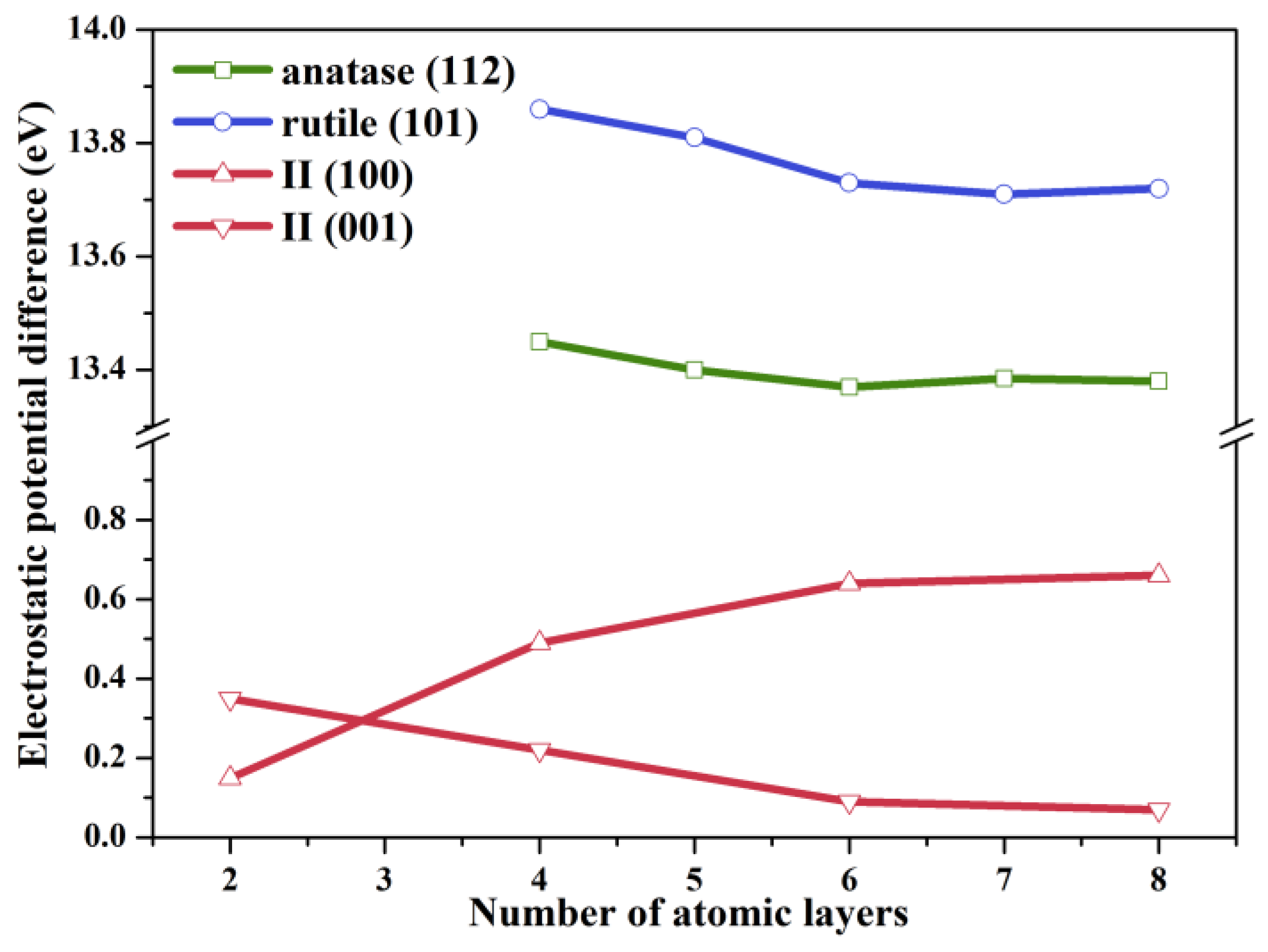
Figure 1. The average electrostatic potential difference plotted against the TiO2 slab thickness of anatase (112), rutile (101), II (100), and II (001) surfaces.
Molecules 29 04105 g001
Figure 2. Optimized geometric heterostructures of (a) (112)A/(100)II and (b) (001)II/(101)R. The “II” stands for the intermediate phase (TiO2-II).
Molecules 29 04105 g002
Figure 3. Calculated work functions of an (a) anatase (112) surface, (b) II (100) surface, (c) rutile (101) surface, and (d) II (001) surface.
Molecules 29 04105 g003
Figure 4. Planar-averaged electron density difference in the Z direction for (a) (112)A/(100)II and (b) (001)II/(101)R heterostructures. The pink and blue isosurfaces represent the electron depletion and accumulation, respectively. The “II” stands for the intermediate phase (TiO2-II).
Molecules 29 04105 g004
Figure 5. Projected density of states (PDOS) of (a) (112)A/(100)II before and after contact and (b) (001)II/(101)R before and after contact. The Fermi level is set at 0 eV.
Molecules 29 04105 g005
Figure 6. (a) Band edge positions relative to the vacuum level of (112)A/(100)II and (001)II/(101)R heterostructures. (b) Illustrations of the proposed band alignment and the charge transfer mechanism in anatase/rutile mixed-phase TiO2. The “II” stands for the intermediate phase (TiO2-II).
Molecules 29 04105 g006
Figure 7. Spatial representations of electron and hole distributions of (a) (112)A/(100)II and (b) (001)II/(101)R heterostructures. Gray and orange areas represent the electron and hole distributions, respectively. The “II” stands for the intermediate phase (TiO2-II).
Molecules 29 04105 g007
Figure 8. Simulated optical absorption spectra of (a) (112)A/(100)II before and after contact and (b) (001)II/(101)R before and after contact.
Molecules 29 04105 g008
Figure 9. Optimized CO2 adsorption geometries on both a pure-phase anatase (112) surface and a (112)A/(100)II heterostructure: (a) tilted linear; (b) perpendicular linear; (c) bidentate carbonate; (d) bridged carbonate. The inserted images show the corresponding CO2 adsorption configurations.
Molecules 29 04105 g009
Scheme 1. Possible reaction pathways and intermediates of the CO2 reduction reaction. The asterisk (*) indicates that the intermediate is adsorbed on the active site. The red parts correspond to the optimal reaction pathways.
Molecules 29 04105 sch001
Figure 10. Potential-energy-change profiles of various possible reaction pathways for photocatalytic CO2 reduction on (a) pure-phase anatase and (b) the (112)A/(100)II heterostructure. The sum of energies of the CO2 molecule and anatase TiO2 is the zero reference for energy. The asterisk (*) indicates that the intermediate is adsorbed on the active site.
Molecules 29 04105 g010
Table 1. Calculated adsorption energies (eV) of CO2 on the pure-phase anatase (Ead,A) and the (112)A/(100)II heterostructure (Ead,A/II).
Adsorption ConfigurationEad,AEad,A/II
L1tilted linear −0.41−0.39
L2perpendicular linear −0.020.21
B1bidentate carbonate0.340.72
B2bridged carbonate0.871.02
Disclaimer/Publisher’s Note: The statements, opinions and data contained in all publications are solely those of the individual author(s) and contributor(s) and not of MDPI and/or the editor(s). MDPI and/or the editor(s) disclaim responsibility for any injury to people or property resulting from any ideas, methods, instructions or products referred to in the content.