


Sodium β-Diketonate Glyme Adducts as Precursors for Fluoride Phases: Synthesis, Characterization and Functional Validation

 ,
,  , ,
, ,  ,
,  and
and 
Abstract
1. Introduction
2. Results and Discussion
- 1
- [Na(hfa)]n
- 1a
- “Na(hfa)•monoglyme”
- 2
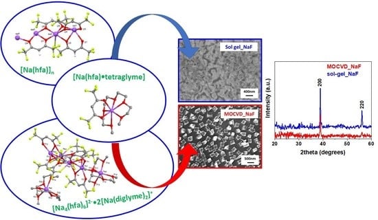
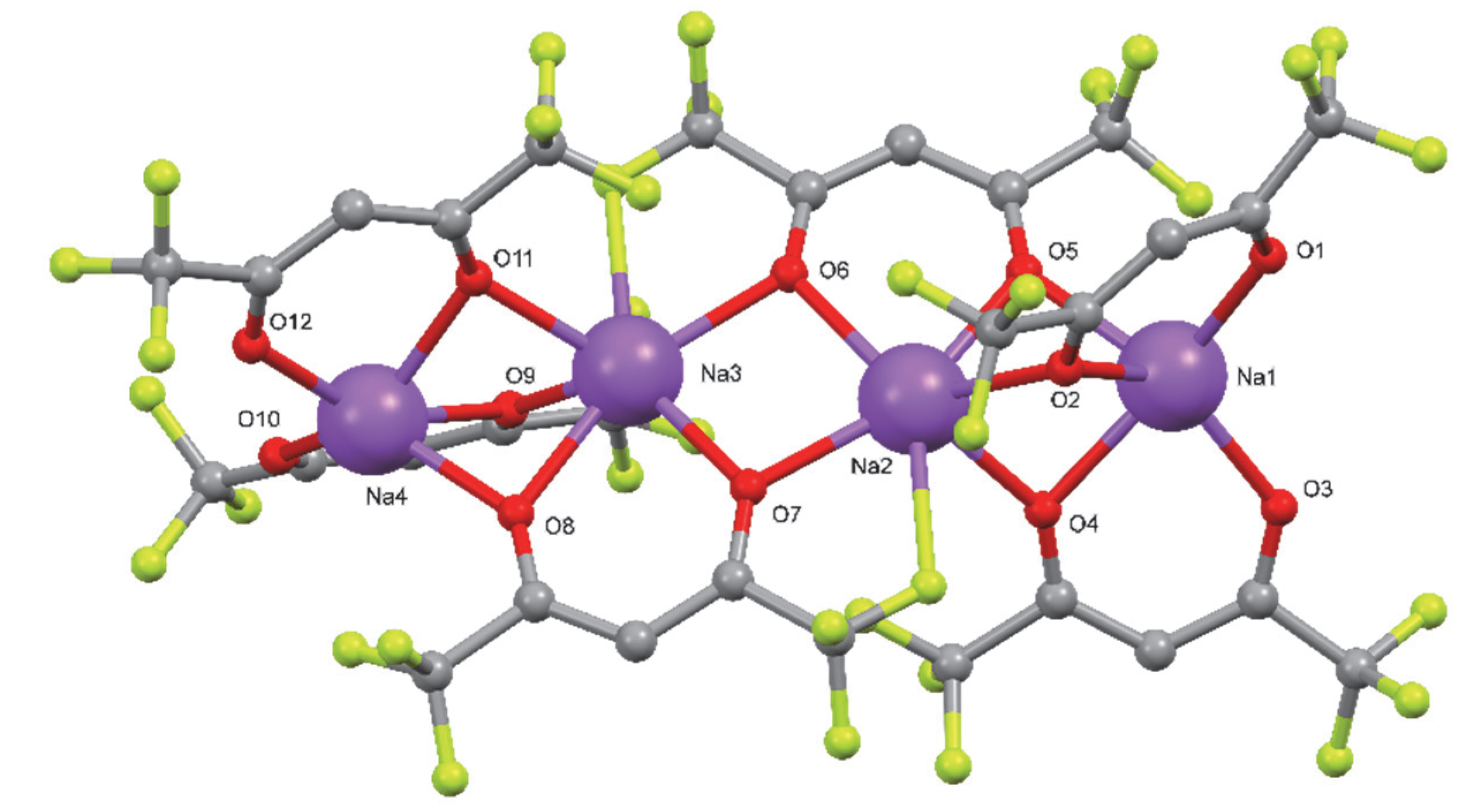
- [Na4(hfa)6]2−•2[Na(diglyme)2]+
- 3
- Na(hfa)•triglyme•H2O
- 4
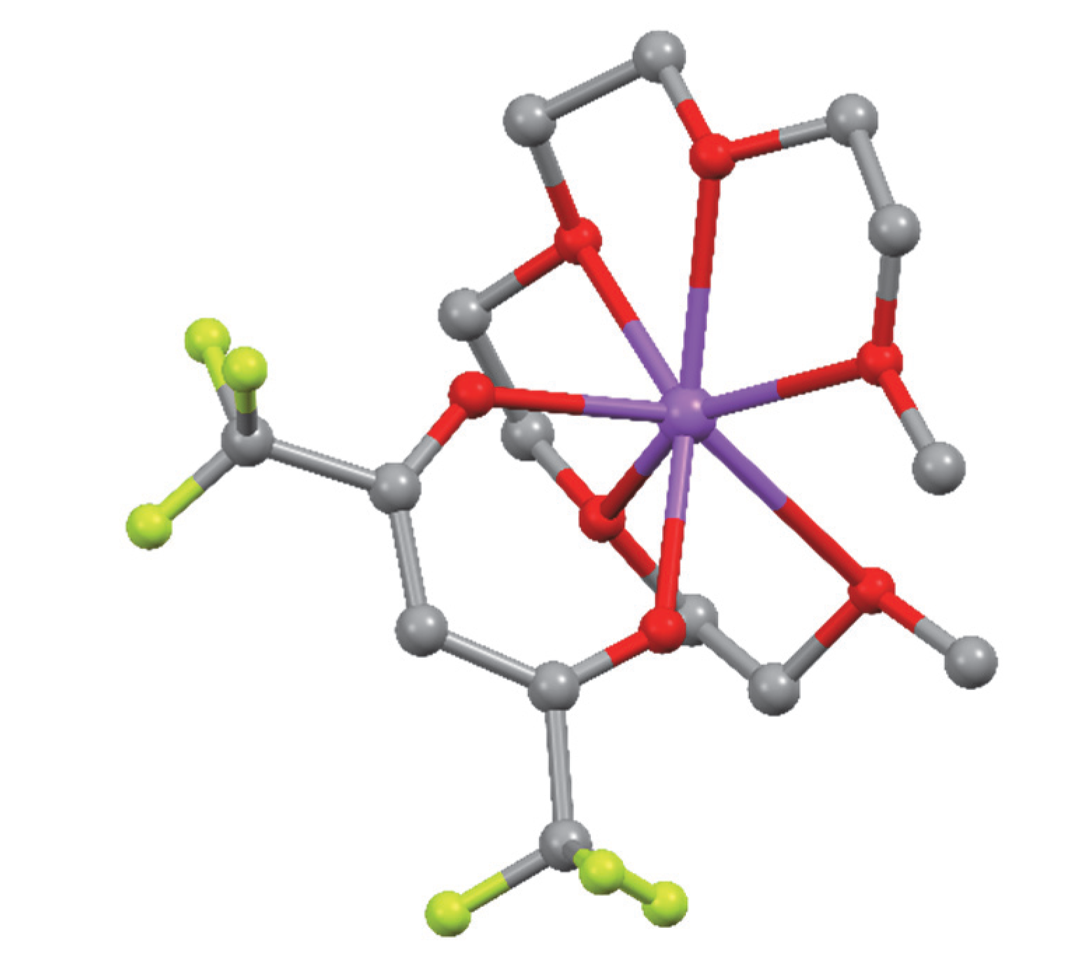
- Na(hfa)•tetraglyme
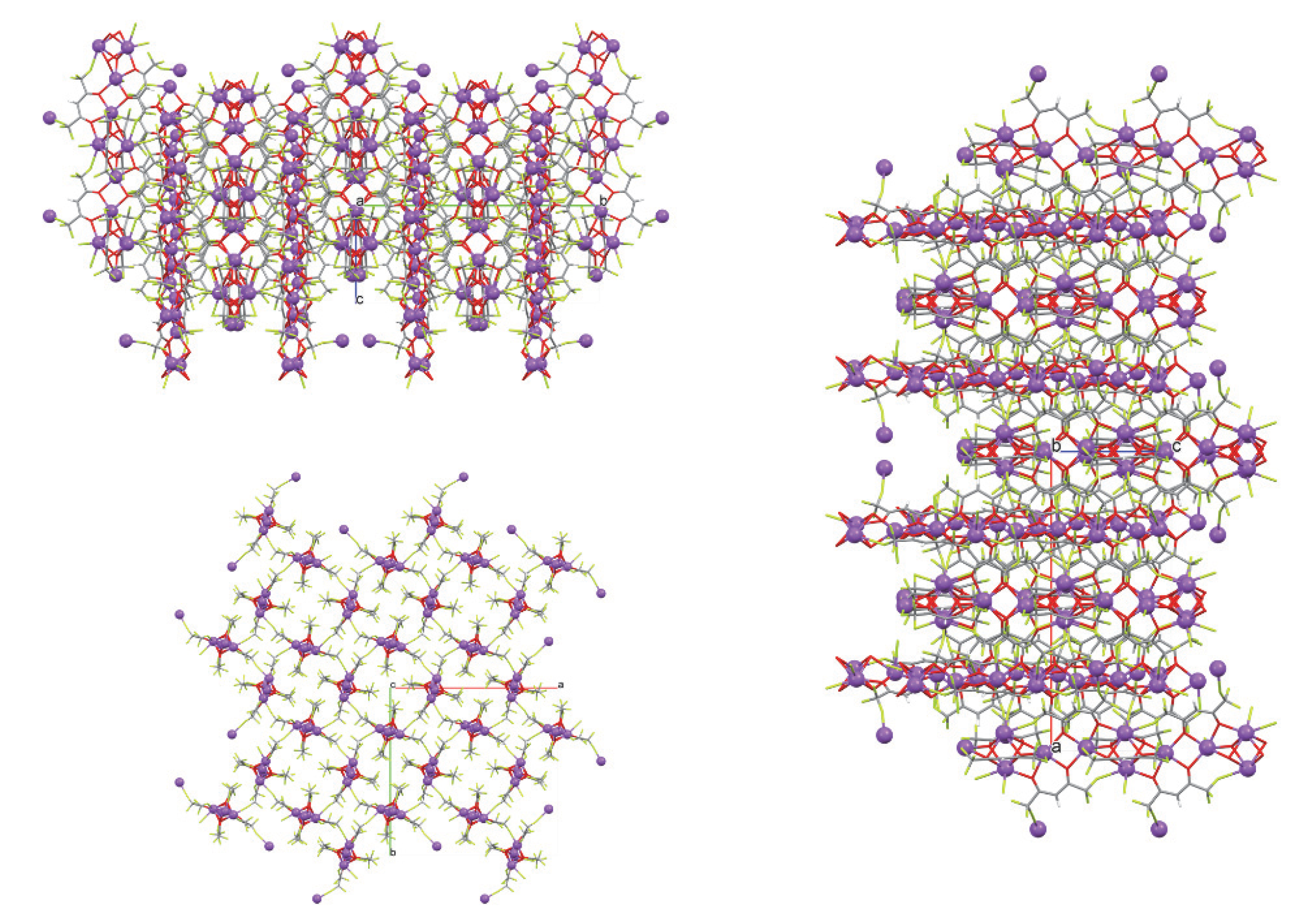
2.1. Single-Crystal Structures
2.2. NMR Characterization
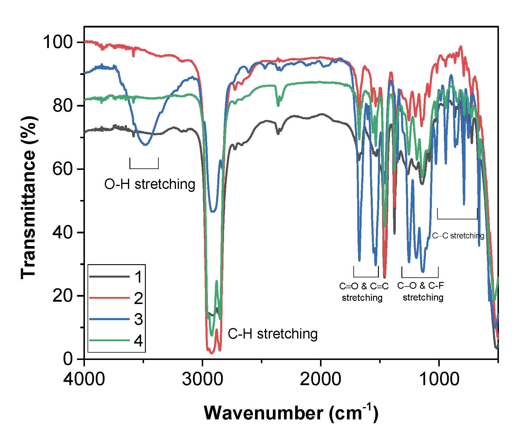
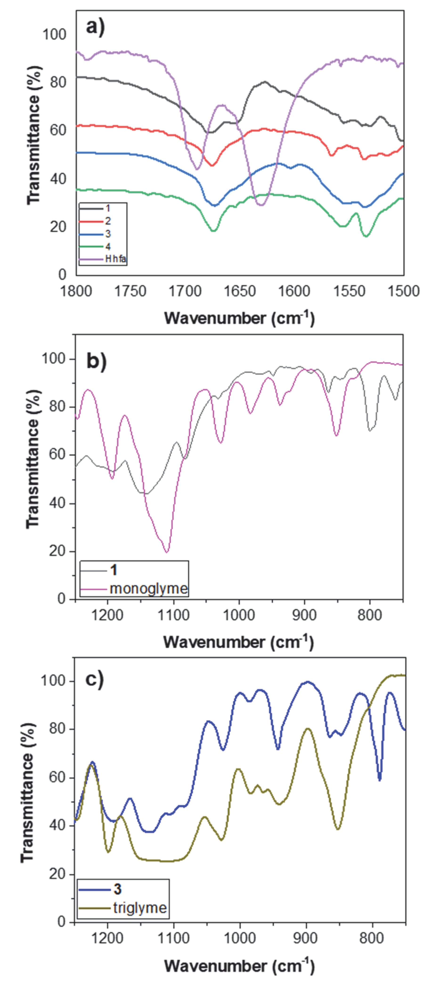
2.3. FT-IR Characterization
2.4. Thermal Analysis
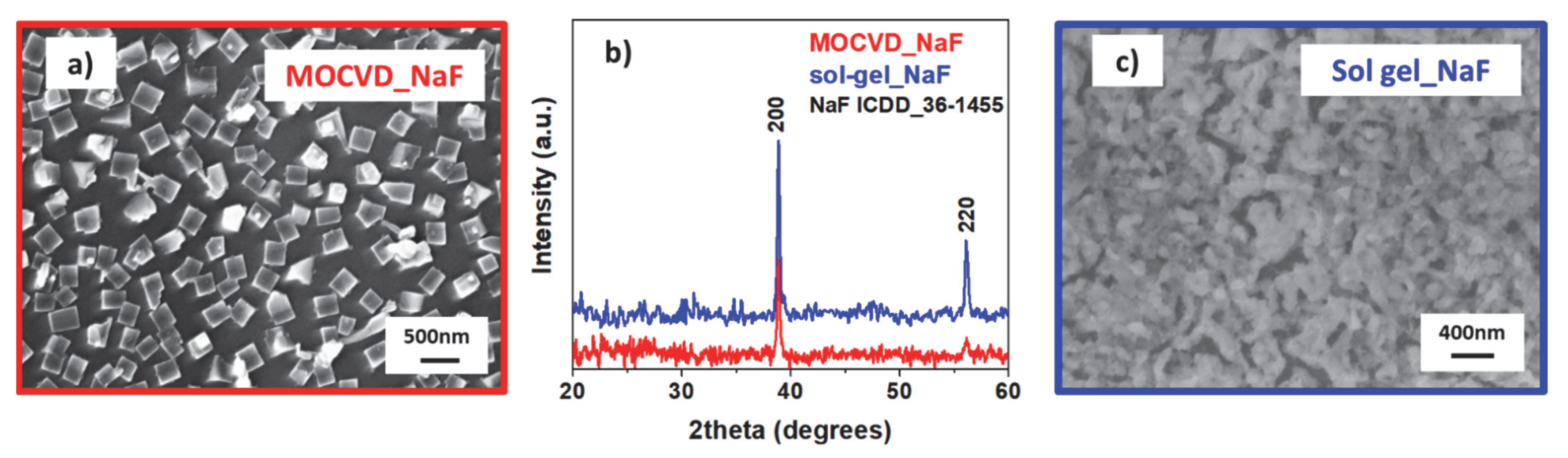
2.5. Growth of NaF Nanostructures
3. Materials and Methods
3.1. Chemical Reagents
3.2. Synthesis and Analytical Data
3.2.1. Synthesis of Na(hfa) (1)
3.2.2. Synthesis of “Na(hfa)•Monoglyme” (1a)
3.2.3. Synthesis of [Na4(hfa)6]2−•2[Na(Diglyme)2]+ (2)
3.2.4. Synthesis of Na(hfa)•Triglyme•H2O (3)
3.2.5. Synthesis of Na(hfa)•Tetraglyme (4)
3.3. Methods
3.3.1. H and 13C NMR Spectroscopy
3.3.2. FT-IR Spectroscopy
3.3.3. Thermogravimetric Analyses
3.3.4. Differential Scanning Calorimetry Analyses
3.3.5. X-ray Crystallographic Procedures
3.4. Synthesis of NaF Nanostructures
4. Conclusions
Supplementary Materials
Author Contributions
Funding
Data Availability Statement
Acknowledgments
Conflicts of Interest
References
- Bittner, M.; Kanas, N.; Hinterding, R.; Steinbach, F.; Räthel, J.; Schrade, M.; Wiik, K.; Einarsrud, M.-A.; Feldhoff, A. A comprehensive study on improved power materials for high-temperature thermoelectric generators. J. Power Sources 2018, 410–411, 143–151. [Google Scholar] [CrossRef]
- Fujii, S.; Yoshiya, M.; Fisher, C.A.J. Quantifying Anharmonic Vibrations in Thermoelectric Layered Cobaltites and Their Role in Suppressing Thermal Conductivity. Sci. Rep. 2018, 8, 11152. [Google Scholar] [CrossRef] [PubMed]
- Medina, E.A.; Aleksandrova, I.; Karppinen, M. Proton intercalation into different CoO2 layer matrices. J. Solid State Chem. 2019, 278, 120899. [Google Scholar] [CrossRef]
- Duk, A.; Schmidbauer, M.; Schwarzkopf, J. Anisotropic one-dimensional domain pattern in NaNbO3 epitaxial thin films grown on (110) TbScO3. Appl. Phys. Lett. 2013, 102, 091903. [Google Scholar] [CrossRef]
- Schwarzkopf, J.; Schmidbauer, M.; Remmele, T.; Duk, A.; Kwasniewski, A.; Bin Anooz, S.; Devi, A.; Fornari, R. Strain-induced phase transitions in epitaxial NaNbO3 thin films grown by metal-organic chemical vapor deposition. J. Appl. Crystallogr. 2012, 45, 1015–1023. [Google Scholar] [CrossRef]
- Cen, Z.; Xu, Z.; Li, L.; Wang, X. Improving the piezoelectric strain and anti-reduction properties of K0.5Na0.5NbO3-based ceramics sintered in a reducing atmosphere. Dalton Trans. 2021, 50, 8851–8862. [Google Scholar] [CrossRef]
- Rajagopalan, R.; Tang, Y.; Jia, C.; Ji, X.; Wang, H. Understanding the sodium storage mechanisms of organic electrodes in sodium ion batteries: Issues and solutions. Energy Environ. Sci. 2020, 13, 1568–1592. [Google Scholar] [CrossRef]
- Slater, M.D.; Kim, D.; Lee, E.; Johnson, C.S. Sodium-Ion Batteries. Adv. Funct. Mater. 2013, 23, 947–958. [Google Scholar] [CrossRef]
- Ezura, Y.; Ishizawa, H. Fluorescent Film, Film-Forming Method Therefor, Multilayer Dielectric Film, Optical Element, Optical System, Imaging Unit, Instrument for Measuring Optical Characteristics, Method of Measuring Optical Characteristics, Exposure Apparatus, Exposure Method, and Device Manufacturing Method. PCT International Application. WO 2009113544A1, 17 September 2009. [Google Scholar]
- Shalav, A.; Richards, B.S.; Green, M.A. Luminescent layers for enhanced silicon solar cell performance: Up-conversion. Sol. Energy Mater. Sol. Cells 2007, 91, 829–842. [Google Scholar] [CrossRef]
- Huang, X.; Han, S.; Huang, W.; Liu, X. Enhancing solar cell efficiency: The search for luminescent materials as spectral converters. Chem. Soc. Rev. 2013, 42, 173–201. [Google Scholar] [CrossRef]
- Tao, F.; Zhang, Z.; Chen, J.; Wang, Z.; Sun, Y. Synthesis and enhancement luminescence of 3D NaReF4 (Re = Eu, Sm) hierarchical microstructures assembled by nanosheets. CrystEngComm 2018, 20, 512–519. [Google Scholar] [CrossRef]
- Wang, Y.; Lu, W.; Yue, D.; Wang, M.; Tian, B.; Li, Q.; Hu, B.; Wang, Z.; Zhang, Y. A strategy to enhance the up-conversion luminescence of nanospherical, rod-like and tube-like NaYF4: Yb3+, Er3+ (Tm3+) by combining with carbon dots. CrystEngComm 2021, 23, 935–943. [Google Scholar] [CrossRef]
- Bond, C.W.; Leonard, R.L.; Erck, R.A.; Terekhov, A.Y.; Petford-Long, A.K.; Johnson, J.A. Pulsed laser deposition of transparent fluoride glass. J. Non-Cryst. Solids 2018, 488, 19–23. [Google Scholar] [CrossRef]
- Akcay, N.; Baskose, U.C.; Ozcelik, S.; Gremenok, V.F.; Zaretskaya, E.P. Na incorporation into Cu2ZnSnS4 thin film absorbers from RF-sputtered NaF precursors. Sol. Energy 2021, 217, 280–291. [Google Scholar] [CrossRef]
- Lingg, L.J.; Berry, A.D.; Purdy, A.P.; Ewing, K.J. Sodium fluoride thin films by chemical vapor deposition. Thin Solid Films 1992, 209, 9–16. [Google Scholar] [CrossRef]
- Samuels, J.A.; Chiang, W.-C.; Yu, C.-P.; Apen, E.; Smith, D.C.; Baxter, D.V.; Caulton, K.G. Chemical Vapor Deposition of Metal Fluorides Using Sodium and Zirconium Fluoroalkoxides. Chem. Mater. 1994, 6, 1684–1692. [Google Scholar] [CrossRef]
- Binions, R.; Carmalt, C.J.; Parkin, I.P. Aerosol-assisted chemical vapour deposition of sodium fluoride thin films. Thin Solid Films 2004, 469, 416–419. [Google Scholar] [CrossRef]
- Kuraitis, S.; Kang, D.; Mane, A.U.; Zhou, H.; Soares, J.; Elam, J.W.; Graugnard, E. Atomic layer deposition of sodium fluoride thin films. J. Vac. Sci. Technol. A 2021, 39, 032405. [Google Scholar] [CrossRef]
- Malik, M.A.; O’brien, P. Basic Chemistry of CVD and ALD Precursors in Chemical Vapor Deposition: Precursors, Processes and Applications; Jones, A.C., Hitchman, M.L., Eds.; Royal Society of Chemistry: Cambridge, UK, 2009. [Google Scholar]
- Bradley, D.C. Volatile metallo-organic precursors for depositing inorganic electronic materials. Polyhedron 1994, 13, 1111–1121. [Google Scholar] [CrossRef]
- Devi, A. ‘Old Chemistries’ for new applications: Perspectives for development of precursors for MOCVD and ALD applications. Coord. Chem. Rev. 2013, 257, 3332–3384. [Google Scholar] [CrossRef]
- Condorelli, G.G.; Malandrino, G.; Fragala, I.L. Engineering of molecular architectures of β-diketonate precursors toward new advanced materials. Coord. Chem. Rev. 2007, 251, 1931–1950. [Google Scholar] [CrossRef]
- Vahlas, C. Chemical Vapor Deposition of Metals: From Unary Systems to Complex Metallic Alloys. In Book Series on Complex Metallic Alloys—Surface Properties and Engineering of Complex Intermetallics; Belin-Ferré, E., Ed.; World Scientific Publishing Co., Pte. Ltd.: Singapore, 2010; Volume 3, pp. 49–81. [Google Scholar]
- Mathur, S.; Singh, A.P.; Mueller, R.; Leuning, T.; Lehnen, T.; Shen, H. Metal-organic chemical vapor deposition of metal oxide films and nanostructures. In Ceramics Science and Technology; Riedel, R., Chen, I.-W., Eds.; Wiley-VCH Verlag GmbH & Co. KGaA: Weinheim, Germany, 2012; Volume 3, pp. 291–336. [Google Scholar]
- Song, X.; Guo, Z.; Zhang, Q.; Zhou, P.; Bao, W.; Zhang, D.W. Progress of Large-Scale Synthesis and Electronic Device Application of Two-Dimensional Transition Metal Dichalcogenides. Small 2017, 13, 1700098. [Google Scholar] [CrossRef]
- Pellegrino, A.L.; Lucchini, G.; Speghini, A.; Malandrino, G. Energy conversion systems: Molecular architecture engineering of metal precursors and their applications to vapor phase and solution routes. J. Mater. Res. 2020, 35, 2950–2966. [Google Scholar] [CrossRef]
- Malandrino, G.; Fragalà, I.L. Lanthanide “second-generation” precursors for MOCVD applications: Effects of the metal ionic radius and polyether length on coordination spheres and mass-transport properties. Coord. Chem. Rev. 2006, 250, 1605–1620. [Google Scholar] [CrossRef]
- Galle Kankanamge, S.R.; Kuroda, D.G. Molecular structure and ultrafast dynamics of sodium thiocyanate ion pairs formed in glymes of different lengths. Phys. Chem. Chem. Phys. 2019, 21, 833–841. [Google Scholar] [CrossRef] [PubMed]
- Terada, S.; Susa, H.; Tsuzuki, S.; Mandai, T.; Ueno, K.; Dokko, K.; Watanabe, M. Glyme-Sodium Bis(fluorosulfonyl)amide Complex Electrolytes for Sodium Ion Batteries. J. Phys. Chem. C 2018, 122, 16589–16599. [Google Scholar] [CrossRef]
- Gotoh, K.; Maruyama, H.; Miyatou, T.; Mizuno, M.; Urita, K.; Ishida, H. Structure and Dynamic Behavior of Sodium-Diglyme Complex in the Graphite Anode of Sodium Ion Battery by 2H Nuclear Magnetic Resonance. J. Phys. Chem. C 2016, 120, 28152–28156. [Google Scholar] [CrossRef]
- Jache, B.; Binder, J.O.; Abe, T.; Adelhelm, P. A comparative study on the impact of different glymes and their derivatives as electrolyte solvents for graphite co-intercalation electrodes in lithium-ion and sodium-ion batteries. Phys. Chem. Chem. Phys. 2016, 18, 14299–14316. [Google Scholar] [CrossRef]
- Fragala, M.E.; Toro, R.G.; Privitera, S.; Malandrino, G. MOCVD fabrication of magnesium fluoride films: Effects of deposition parameters on structure and morphology. Chem. Vap. Depos. 2011, 17, 80–87. [Google Scholar] [CrossRef]
- Fragalà, M.E.; Toro, R.G.; Rossi, P.; Dapporto, P.; Malandrino, G. Synthesis, Characterization, and Mass Transport Properties of a Self-Generating Single-Source Magnesium Precursor for MOCVD of MgF2 Films. Chem. Mater. 2009, 21, 2062–2069. [Google Scholar] [CrossRef]
- Pellegrino, A.L.; La Manna, S.; Bartasyte, A.; Cortelletti, P.; Lucchini, G.; Speghini, A.; Malandrino, G. Upconverting tri-doped calcium fluoride-based thin films: A comparison of the MOCVD and sol-gel preparation methods. J. Mater. Chem. C 2020, 8, 3865–3877. [Google Scholar] [CrossRef]
- Malandrino, G.; Perdicaro, L.M.S.; Fragalà, I.L. Effects of processing parameters in the MOCVD growth of nanostructured lanthanum trifluoride and oxyfluoride thin films. Chem. Vap. Depos. 2006, 12, 736–741. [Google Scholar] [CrossRef]
- Lo Nigro, R.; Malandrino, G.; Fragalà, I.L.; Bettinelli, M.; Speghini, A. MOCVD of CeF3 films on Si(100) substrates: Synthesis, characterization and luminescence spectroscopy. J. Mater. Chem. 2002, 12, 2816–2819. [Google Scholar] [CrossRef]
- Malandrino, G.; Incontro, O.; Castelli, F.; Fragalà, I.L.; Benelli, C. Synthesis, Characterization, and Mass-Transport Properties of Two Novel Gadolinium(III) Hexafluoroacetylacetonate Polyether Adducts: Promising Precursors for MOCVD of GdF3. Films Chem. Mater. 1996, 8, 1292–1297. [Google Scholar] [CrossRef]
- Schueler, P.; Goerls, H.; Westerhausen, M.; Krieck, S. Bis(trimethylsilyl)amide complexes of s-block metals with bidentate ether and amine ligands. Dalton Trans. 2019, 48, 8966–8975. [Google Scholar] [CrossRef] [PubMed]
- Devaine-Pressing, K.; Oldenburg, F.J.; Menzel, J.P.; Springer, M.; Dawe, L.N.; Kozak, C.M. Lithium, sodium, potassium and calcium amine-bis(phenolate) complexes in the ring-opening polymerization of rac-lactide. Dalton Trans. 2020, 49, 1531–1544. [Google Scholar] [CrossRef] [PubMed]
- Tsymbarenko, D.; Korsakov, I.; Mankevich, A.; Girichev, G.; Pelevina, E.; Kaul, A. New complexes of alkali-metals as precursors for MOCVD of ferroelectric (K,Na)NbO3 thin films. ECS Trans. 2009, 25, 633–638. [Google Scholar] [CrossRef]
- Catalano, M.R.; Pellegrino, A.L.; Rossi, P.; Paoli, P.; Cortelletti, P.; Pedroni, M.; Speghini, A.; Malandrino, G. Upconverting Er3+, Yb3+ activated β-NaYF4 thin films: A solution route using a novel sodium β-diketonate polyether adduct. New J. Chem. 2017, 41, 4771–4775. [Google Scholar] [CrossRef]
- Peddagopu, N.; Rossi, P.; Bonaccorso, C.; Bartasyte, A.; Paoli, P.; Malandrino, G. Facile synthesis of novel lithium β-diketonate glyme adducts: The effect of molecular engineering on the thermal properties. Dalton Trans. 2020, 49, 1002–1006. [Google Scholar] [CrossRef]
- Peddagopu, N.; Sanzaro, S.; Rossi, P.; Paoli, P.; Malandrino, G. A One-Pot Synthesis of “K(hfa) glyme” Adducts: Effect of the Polyether Length on the Ion Coordination Sphere. Eur. J. Inorg. Chem. 2021, 2021, 3776–3780. [Google Scholar] [CrossRef]
- Pellegrino, A.L.; Catalano, M.R.; Cortelletti, P.; Lucchini, G.; Speghini, A.; Malandrino, G. Novel sol-gel fabrication of Yb3+/Tm3+ co-doped β-NaYF4 thin films and investigation of their upconversion properties. Photochem. Photobiol. Sci. 2018, 17, 1239–1246. [Google Scholar] [CrossRef] [PubMed]
- CrysAlisPro; Agilent Technologies: Santa Clara, CA, USA, 2011.
- Burla, M.C.; Caliandro, R.; Camalli, M.; Carrozzini, B.; Cascarano, G.L.; Da Caro, L.; Giacovazzo, C.; Polidori, G.; Spagna, R. SIR2004: An improved tool for crystal structure determination and refinement. J. Appl. Cryst. 2005, 38, 381–388. [Google Scholar] [CrossRef]
- Gruene, T.; Hahn, H.W.M.; Luebben, A.V.; Meilleur, F.; Sheldrick, G.M. Refinement of macromolecular structures against neutron data with SHELXL2013. J. Appl. Cryst. 2014, 47, 462–466. [Google Scholar] [CrossRef] [PubMed]
- Nardelli, M. PARST95—An update to PARST: A system of Fortran routines for calculating molecular structure parameters from the results of crystal structure analyses. J. Appl. Cryst. 1995, 28, 659. [Google Scholar] [CrossRef]
- Macrae, C.F.; Bruno, I.J.; Chisholm, J.A.; Edgington, P.R.; McCabe, P.; Pidcock, E.; Rodriguez-Monge, E.; Taylor, R.; van de Streek, J.; Wood, P.A. Mercury CSD 2.0—New Features for the Visualization and Investigation of Crystal Structures. J. Appl. Cryst. 2008, 41, 466–470. [Google Scholar] [CrossRef]


| 1H NMR | 13C NMR | |||||
|---|---|---|---|---|---|---|
| Complex | CO-CH=C-O− | Polyether a | CO-CH=C-O− | CO-CH=C-O− | CF3 | Polyether a |
| 1 | 5.62 (s) | - | 85.50 | 175.35 (q, 2JCF = 30.7 Hz) | 119.16 (q, 1JCF = 290.3 Hz) | - |
| 2 | 5.65 (s, 6H) | a: 3.33 (s, 24H) b, 3.50 (m, 16H) c: 3.58 (m, 16 H) | 85.44 | 175.28 (q, 2JCF = 30.6 Hz) | 119.17 (q, 1JCF = 290.1 Hz) | a: 58.83 b: 70.79 c: 72.45 |
| 3 | 5.65 (s, 1H) | a: 3.33 (s, 6H) b: 3.51(m, 4H) c, d: 3.59 (m, 8H) | 84.54 | 174.35 (q, 2JCF = 30.7 Hz) | 118.25 (q, 1JCF = 290.1 Hz) | a: 57.99 b, c: 69.58 d: 71.22 |
| 4 | 5.63 (s, 1H) | a: 3.3a (s, 6H) b: 3.51 (m, 4H) c, d, e: 3.59 (m, 12H) | 85.43 | 175.22 (q, 2JCF = 30.7 Hz) | 119.19 (q, 1JCF = 290.2 Hz) | a: 58.96 b: 70.32 c, d: 70.38 e: 72.13 |
Publisher’s Note: MDPI stays neutral with regard to jurisdictional claims in published maps and institutional affiliations. |
© 2022 by the authors. Licensee MDPI, Basel, Switzerland. This article is an open access article distributed under the terms and conditions of the Creative Commons Attribution (CC BY) license (https://creativecommons.org/licenses/by/4.0/).
Share and Cite
Peddagopu, N.; Pellegrino, A.L.; Bonaccorso, C.; Rossi, P.; Paoli, P.; Malandrino, G. Sodium β-Diketonate Glyme Adducts as Precursors for Fluoride Phases: Synthesis, Characterization and Functional Validation. Molecules 2022, 27, 6282. https://doi.org/10.3390/molecules27196282
Peddagopu N, Pellegrino AL, Bonaccorso C, Rossi P, Paoli P, Malandrino G. Sodium β-Diketonate Glyme Adducts as Precursors for Fluoride Phases: Synthesis, Characterization and Functional Validation. Molecules. 2022; 27(19):6282. https://doi.org/10.3390/molecules27196282
Chicago/Turabian StylePeddagopu, Nishant, Anna L. Pellegrino, Carmela Bonaccorso, Patrizia Rossi, Paola Paoli, and Graziella Malandrino. 2022. "Sodium β-Diketonate Glyme Adducts as Precursors for Fluoride Phases: Synthesis, Characterization and Functional Validation" Molecules 27, no. 19: 6282. https://doi.org/10.3390/molecules27196282
APA StylePeddagopu, N., Pellegrino, A. L., Bonaccorso, C., Rossi, P., Paoli, P., & Malandrino, G. (2022). Sodium β-Diketonate Glyme Adducts as Precursors for Fluoride Phases: Synthesis, Characterization and Functional Validation. Molecules, 27(19), 6282. https://doi.org/10.3390/molecules27196282