In electrochemistry, cyclic voltammetry (CV), Tafel polarization, and electrochemical impedance spectra (EIS) measurements are usually used to determine electro-catalytic performance. CV precisely quantifies the overall electro-catalytic ability and kinetic reduction capability of an electro-catalyst by two parameters: (1) the cathodic peak current density (
Jpc) and (2) the peak potential separation (Δ
Ep). The
Jpc is defined as the net peak current density from the cathodic current peak to the background curve. The Δ
Ep is defined as the potential difference between the anodic and cathodic current peaks. Generally, a larger
Jpc presents a better overall electrocatalytic ability. On the other hand, a lower Δ
Ep indicates a lower overpotential to trigger redox reaction [
29,
33].
EIS is used to acquire ohmic series resistance (
RS) and the charge-transfer resistance (
Rct-EIS) of electro-catalytic film in the Nyquist plot. Usually, EIS measurement is applied to the dummy cell system, which is a two-electrode system. It is also used for the study of electro-catalyst materials and their Nyquist plot, which shows two semicircles. In the high-frequency zone, the onset point of the first semicircle is ohmic series resistance (
RS), which relates to the resistance between the substrate and electro-catalytic material. In the middle-frequency zone, the radius of the first semicircle is the charge transfer resistance (
Rct-EIS), which refers to the charge transfer resistance between the electro-catalytic film and the electrolyte [
5,
34].
In photoelectric conversion, there are the overall solar-to-electrical energy conversion efficiency (
η), the short-circuit current (
JSC), open-circuit photovoltage (
VOC), and the fill factor of the cell (
FF). Commonly, electrocatalytic ability positively relates to the
JSC, i.e., the better electrocatalytic ability shows larger
JSC. The film formation and properties of electro-catalytic materials also obviously influence the values of
η,
JSC,
VOC, and
FF [
3,
35].
Next, we will discuss the various strategies and characteristics of carbon materials, conductive polymer materials, metal compound materials, and hybrids compound materials step-by-step.
2.1. Carbon Electro-Catalysts
Carbon materials have high electrical conductivity, good corrosion resistance, strong thermal stability, and adjustable energy levels. They are broadly classified into the following two types: (1) sp
3-hybridization (e.g., amorphous porous carbon, carbon nanotube, carbon black, and activated carbon) and (2) sp
2-hybridization (e.g., graphite, carbon nanotube, graphene, and fullerenes) [
21,
25,
36,
37,
38,
39]. However, carbon materials possess a smaller number of defective sites. To overcome this issue, the following three strategies are usually employed: (1) increasing the reaction surface area of carbon materials; (2) embedding the heteroatoms into the basal layers; (3) designing the specific electron pathway of electro-catalysts. Here, we list several pieces of literature with strategies for promoting the efficiency of DSSCs [
2,
21,
23,
37,
40,
41,
42,
43,
44,
45,
46,
47].
Younas et al. obtained highly mesoporous carbon (HMC) through the adoption of the template method [
48]. HMC2021 was grown with a 2:1 ratio of carbon precursor, and 20 nm colloidal silica shows mesoporosity and the greatest BET (Brunauer–Emmett–Teller) surface area among HMC412 (747 m
2 g
−1), HMC411 (947 m
2 g
−1), HMC1211 (628 m
2 g
−1), and HMC2021 (1037 m
2 g
−1). As shown in
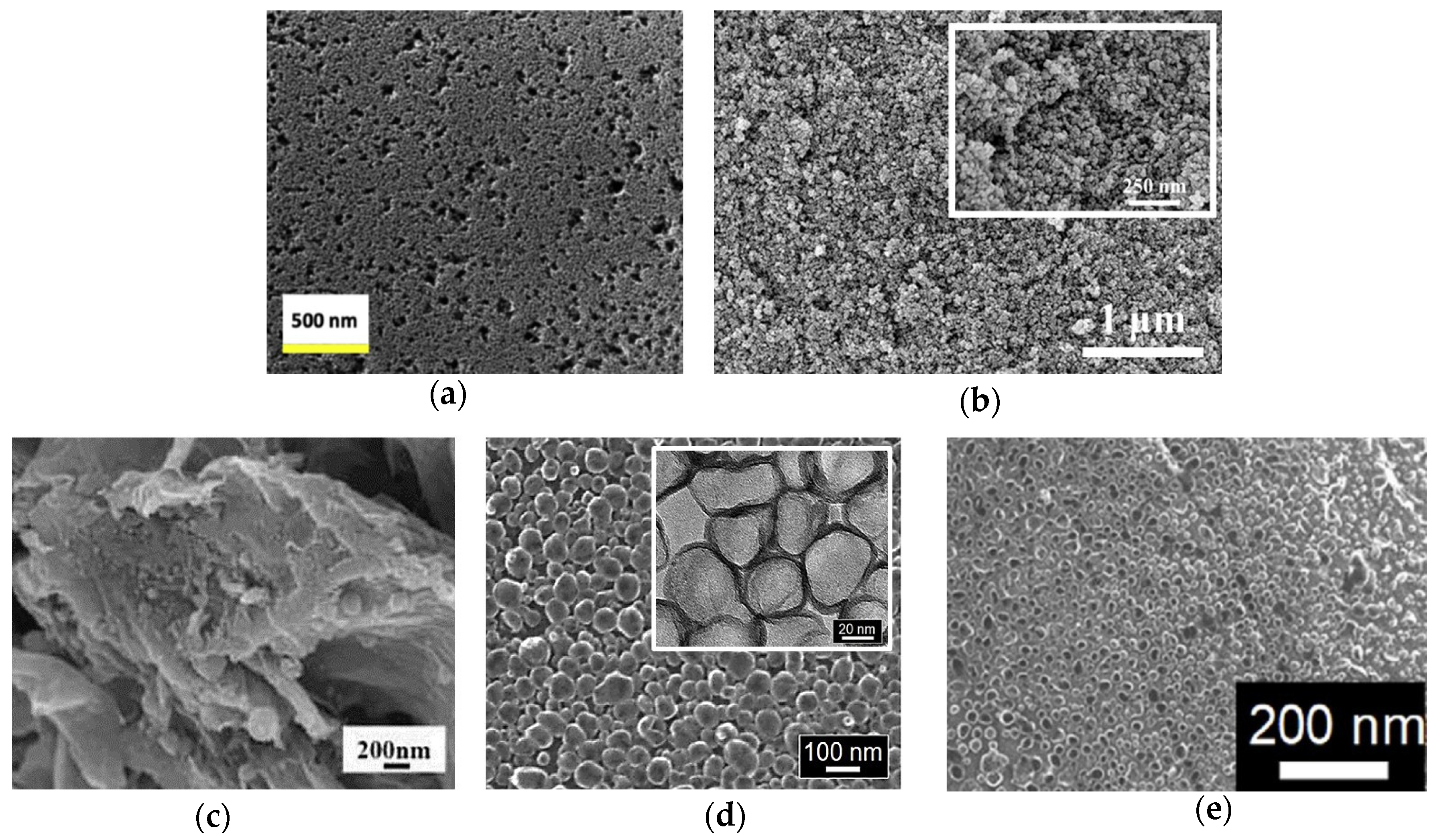
Figure 3a, the pore size and the diameter of the HMC2021 nanoparticles were 30–60 nm and ~20 nm, respectively. HMC2021 displayed the best
η of 8.77% and the lowest
Rct-EIS of 9 Ω cm
2, which can be attributed to the large enhancement of electrocatalytic activity, as shown in
Table 1 and
Table 2. According to the results, the mesopore size and the surface area had a great correlation with electrocatalytic activity.
Table 1.
The photovoltaic parameters of various carbon electrocatalysts in the DSSCs with an I−/I3− redox couple and N719 dye are compared under 1.0 sun (AM 1.5G, 100 mW cm−2).
Table 1.
The photovoltaic parameters of various carbon electrocatalysts in the DSSCs with an I−/I3− redox couple and N719 dye are compared under 1.0 sun (AM 1.5G, 100 mW cm−2).
| Sample | η (%) | η of Pt (%) | JSC (mA cm−2) | VOC (V) | FF | Surface Area (m2 g−1) | Ref. |
|---|
| HMC2021 | 8.77 | 7.57 | 16.10 | 0.81 | 0.68 | 1037 | [48] |
| CA-C | 9.08 | 7.92 | 16.59 | 0.77 | 0.71 | 724 | [49] |
| N-CNOs/mGr | 10.28 | 6.54 | 23.19 | 0.76 | 0.58 | N/A | [50] |
| GD-1@hGO | 9.10 | 8.80 | 16.00 | 0.74 | 0.78 | 353 | [51] |
| N-GHBs/CC | 7.53 | 7.70 | 16.09 | 0.70 | 0.67 | N/A | [52] |
| N,S-GHBs/CC | 9.02 | 8.90 | 15.71 | 0.80 | 0.72 | N/A | [53] |
Table 2.
The electrochemical parameters of various carbon materials CEs under I−/I3− redox couple.
Table 2.
The electrochemical parameters of various carbon materials CEs under I−/I3− redox couple.
| Sample | Jpc (mA cm−2) | ΔEp (V) | Rct-EIS (Ω cm2) | Ref. |
|---|
| HMC2021 | N/A | N/A | 9.00 | [48] |
| CA-C | 1.40 | N/A | 3.96 | [49] |
| N-CNOs/mGr | 1.61 | 0.56 | 2.30 | [50] |
| GD-1@hGO | 3.00 | 0.34 | 1.30 | [51] |
| N-GHBs/CC | 1.68 | 0.55 | 10.73 | [52] |
| N,S-GHBs/CC | 2.22 | 0.46 | 0.15 | [53] |
Figure 3.
The SEM images of (
a) HMC2021 [
48], (
b) CA-C [
49], (
c) N-CNOs/mGr [
50], (
d) N-GHBs (inset shows their TEM images) [
52], and (
e) N,S-GHBs [
53].
Figure 3.
The SEM images of (
a) HMC2021 [
48], (
b) CA-C [
49], (
c) N-CNOs/mGr [
50], (
d) N-GHBs (inset shows their TEM images) [
52], and (
e) N,S-GHBs [
53].
Huang et al. synthesized pristine mesoporous carbon aerogels (CA) by means of various resorcinol (R)/formaldehyde (F) and resorcinol (R)/sodium carbonate (C) molar ratios, as shown in
Figure 4a [
49]. The R/F molar ratio and R/C ratio of CA-C was 377 and 0.76, respectively. Moreover, its specific surface area was up to 724 m
2 g
−1 and showed the smallest particle size of approximately 50 nm in diameter in the study (
Figure 3b). The CA-C had the best
η of 9.08%, the largest
Jpc of 1.40 mA cm
−2, the lowest
Rct-EIS of 3.18 Ω cm
2, and the smallest
Rct-EIS of 3.96 Ω cm
2 among the various CAs in the study, as shown in
Table 1 and
Table 2. Furthermore, the DSSC with the CA-C exhibitrf an impressive
η of 20.1 ± 0.60% under a T5 lamp with 7000 lux (2.18 mW cm
−2). Here, the specific surface areas could be increased by tuning the precursor ratio to enhance the electrocatalytic ability. Moreover, the DSSC with the CA-C demonstrates that the carbon electro-catalysts could be used in indoor solar cell applications.
Pang et al. synthesized N-doped carbon nano-onion (N-CNO) with modified graphene (mGr). The diameter of N-CNO and the thickness of mGr were 40–60 nm and 10–30 nm, respectively, as shown in
Figure 3c [
50]. The N-CNOs/mGr showed the best
η of the 10.28% among the mGr (5.11%), and the Pt (6.54%), as shown in
Table 1. In
Table 2, N-CNOs/mGr shows an
Jpc of 1.61 mA cm
−2 and a
Rct-EIS of 2.30 Ω cm
2, which are of better electrocatalytic ability than mGr (
Jpc of 1.61 mA cm
−2 and
Rct-EIS of 8.96 Ω cm
2) and the Pt (
Jpc of 1.61 mA cm
−2 and
Rct-EIS of 0.15 Ω cm
2). In the N-CNOs/mGr CEs, the N-CNOs could offer extra active sits for the reduction, and the mGr network benefitted intrinsic charge transfer.
Ali et al. acquired nitrogen-doped graphene quantum dots (NGQDs) from the hydrothermal cutting method with DMA adjustment (antisolvent) [
51]. The GD-1@hGO morphology consisted of GD-1 (nanorod with 1 μm length and 3 μm width) and holey graphene oxide (hGO, nanosheet with irregular porous). In BET measurement, the GD-1@hGO, the hGO, and the rGO exhibited BET areas of 353, 135, and 60 m
2 g
−1, respectively. The GD-1@hGO presents the best
η of 9.10% compared to the hGO (6.70%), the rGO (5.10%), and Pt (8.80%), as shown in
Table 1. In electrochemical performance, the GD-1@hGO exhibited the largest
Jpc of 3.00 mA cm
−2 and the lowest
Rct-EIS of 1.30 Ω cm
2 compared to the hGO (
Jpc of 1.61 mA cm
−2 and
Rct-EIS of 8.96 Ω cm
2), the rGO (
Jpc of 1.61 mA cm
−2 and
Rct-EIS of 8.96 Ω cm
2), and the Pt (
Jpc of 1.61 mA cm
−2 and
Rct-EIS of 8.96 Ω cm
2), as shown in
Table 2. The GD-1@hGO demonstrated more electrocatalytic activity, good electrolyte diffusion, and multidimensional charge transport channels.
Tseng et al. had grown nitrogen-doped graphene hollow nanoballs on carbon cloth (CC) (named N-GHBs) via the chemical vapor deposition (CVD) method, as shown in
Figure 4b [
52]. From SEM (
Figure 3d) and TEM (inset of
Figure 3d) images, the nanoball diameter of the N-GHBs was shown to be around 50–100 nm, and the thickness of the nanoball shell was about 3.5 nm, corresponding to approximately 10 layers of graphene. The catalytic activity of CC, GHBs, N-GHBs, and Pt were investigated along with photovoltaic parameters and IV curves in DSSCs; they are shown in
Table 1. The N-GHBs reveals the best
η among the CC (0.48%), the GHBs (6.20%), the N-GHBs (7.53%), and the Pt (7.70%). Moreover, the N-GHBs exhibited close electrocatalytic performance to Pt based on CV and EIS measurements, as shown in
Table 2. These good results are contributed to by GHBs, which offer an increase of the specific surface area and the N-doped states in graphene to significantly enhance electrocatalytic activity.
Chang et al. grew heteroatoms-doped graphene hollow nanoballs (GHBs) on flexible carbon cloth (CC) by means of a CVD reaction with nitrogen (N) and sulfur (S) atoms, as shown in
Figure 4c [
53]. As seen in the SEM images (
Figure 3e), the thickness and the diameter of the hollow nanoballs of N,S-GHBs were about 3.5 nm and 20–50 nm, respectively. Compared to various CEs in a DSSC, the N,S-GHBs showed the best
η of 9.02% among the GHBs (6.47%), the N-GHBs (7.48%), the S-GHBs (8.15%), N,S-GHBs, and the Pt (8.90%), as shown in
Table 1. In electrochemical performance, the N,S-GHBs still revealed the best electrocatalytic ability (
Jpc of 2.22 mA cm
−2 and
Rct-EIS of 0.15 Ω cm
2), as shown in
Table 2. In this study, the electrocatalytic ability of carbon electro-catalysts was the N,S-GHBs > the S-GHBs > the N-GHBs > the GHBs. These results indicate that the heteroatoms-doped strategy could be used to obviously boost the electrocatalytic ability.
In this carbon electro-catalyst section, there are three major strategies to enhance the DSSC performance: (1) creating active sites (e.g., N-doped carbon, S-doped carbon, etc.), (2) increasing specific surface areas via controlling precursors and template methods, and (3) constructing specific electron pathways using the specific structures and multidimensional structures. Accordingly, the disadvantages of the carbon electro-catalysts have been sufficiently overcome for holding a promising means to replace Pt in the future.
A brief summary of this section follows: Younas et al. developed a high-performance CE material (i.e., highly mesoporous carbon) by greatly enhancing the specific surface area for the electro-catalytic reaction. Additionally, Huang et al. utilized the same concept to boost the electro-catalytic ability of their Pt-free CE using mesoporous carbon aerogels. On the other hand, Pang et al. introduced the heteroatom-doped technology to increase the active sites of their carbon catalyst (i.e., N-doped carbon nano-onion) in conjunction with 2D-layered graphene (i.e., modified graphene) to facilitate the intrinsic charge transfer property. Further, Ali et al. used the same approach of heteroatom-doped technology to prepare nitrogen-doped graphene quantum dots composited with holey graphene oxide sheets for the use of Pt-free CE in DSSCs; where, the edge-site rich graphene quantum dots could provide more active site area for the electro-catalytic reaction compared to pristine 2D graphene materials (note: the basal plane of pristine graphene usually has poor activity for a electro-catalytic reaction). To address the issue of poor activity on the basal plane of pristine graphene, both the insertion of heteroatom into the basal plane of graphene and the structural engineering of 2D graphene to 3D shape/morphology approaches were adopted by Tseng et al. to effectively enhance the electro-catalytic ability of their graphene-based CE (i.e., N-doped graphene hollow nanoballs). Meanwhile, Chang et al. further improved the performance of the graphene-based CE based on the report of Tseng et al. via diatomic doping (N,S-doped graphene hollow nanoballs). Finally, the DSSCs with above carbon-based CEs almost exhibited superior cell performance than those of the cells with a Pt electrode.
2.2. Conductive Polymer Electro-Catalysts
Due to the flexible properties, good electrical conductivity, good adhesion to the substrates, and easy integration with roll-to-roll processes [
31,
54,
55,
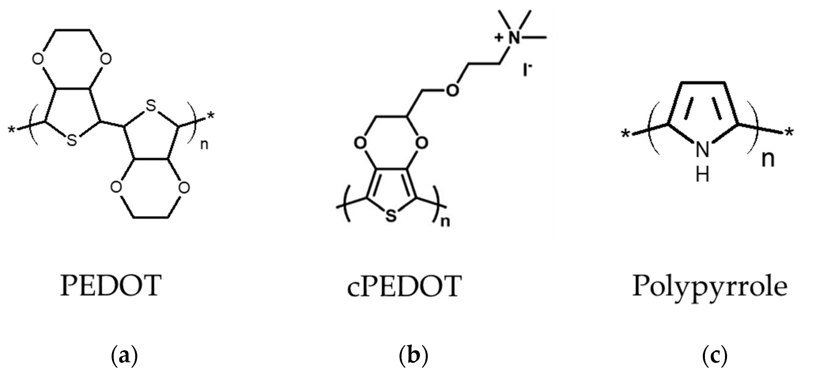
56], several conductive polymer electro-catalysts such as PEDOT:PSS, PEDOT-MeOH, cPEDOT, PEDOT, PProDOT, PANI, and PPy are used in DSSCs. In this section, the PEDOT, cPEDOT, and PPPy (
Figure 5) are chosen for further discussion because they have been demonstrated to perform well in various redox couples (Cu
2+/Cu
+ and I
−/I
3−), dyes (Y123, D35/XY1, XY1b/Y123, D149, and N719), light sources, and irradiation powers (10, 12, 50, 100 mW cm
−2) [
28,
35,
54,
57,
58,
59,
60,
61,
62,
63,
64,
65,
66,
67]. Here, three strategies are listed to improve the performance of DSSCs with conductive polymer electro-catalysts: (1) the different dyes or electrolytes are allocated the DSSC with the conductive polymers; (2) the conductive polymers are linked to the specific functional group; (3) the reaction surface areas are increased in the conductive polymers.
Cao et al. synthesized the PEDOT on FTO glass, incorporating it with Y123 dye and solid-state Cu
+/Cu
2+ electrolytes for solid-state DSSC [
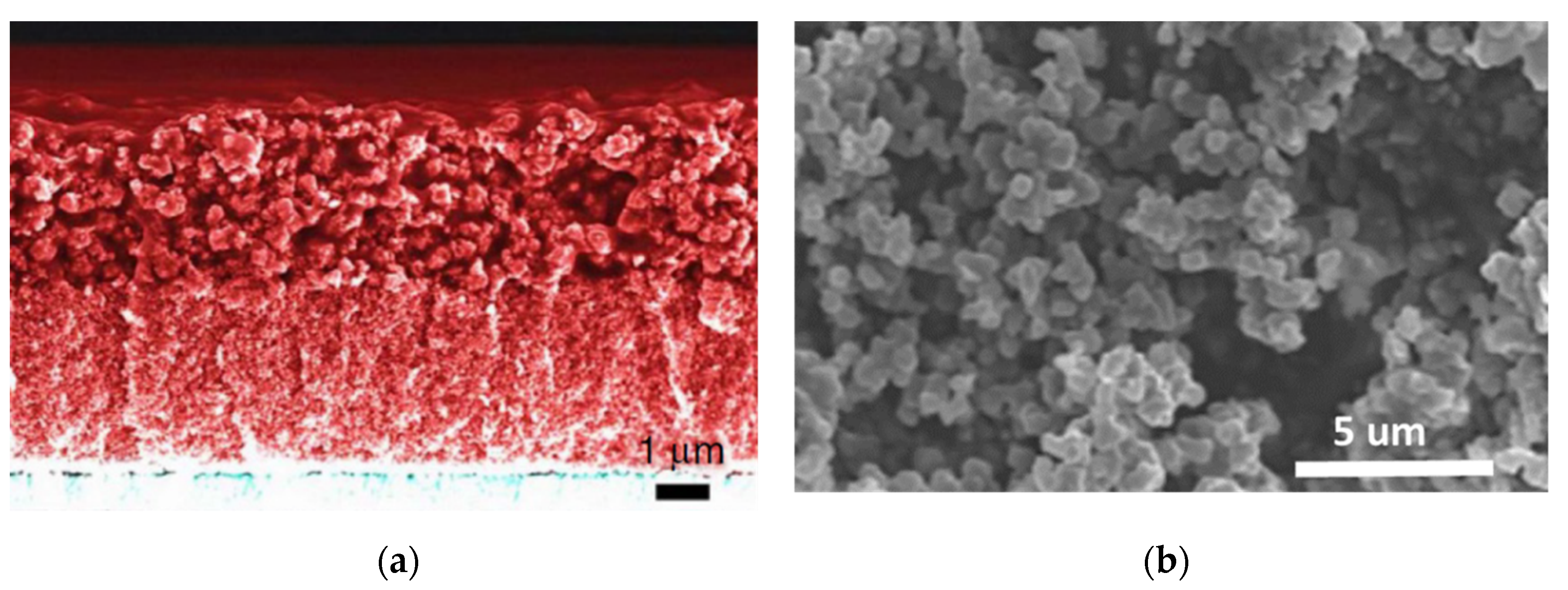
35]. The PEDOT molecular structure and the solid-state DSSC cross section are shown in
Figure 5a and
Figure 6a, respectively. The solid-state DSSC shows the
η of 11.00%, 11.30%, and 10.05% at the irradiation powers of 100, 50, and 10 mW cm
−2, respectively, as shown in
Table 3. For long-term stability testing, the
η of solid-state DSSCs with the PEDOT is still up to 9.50%, even after a 35-day testing period. Due to the incorporation of Cu
+/Cu
2+ electrolytes and Y123 dye, the disadvantages of PEDOT CEs, such as instability and low electrocatalytic ability, could be eliminated, promising future for DSSC.
Freitag et al. obtained PEDOT films via the electrochemically deposited method, incorporating with D35/XY1 co-sensitizing dye and copper complex Cu(II/I)(tmby) electrolyte for fabricating DSSCs [
63]. The DSSC reveals the
η of 11.40% and 13.20% at an irradiation power of 100 and 12 mW cm
−2, respectively, as shown in
Table 3. The DSSC performance is increased with decreasing irradiation power, indicating that DSSC can be well used in various weather conditions such as on sunny, cloudy, and rainy days. Furthermore, the
η of the DSSCs are 28.90% and 25.50% under indoor-light illumination at a power of 0.306 and 0.061 mW cm
−2. These results support the DSSC for use in various irradiation conditions with different light sources.
Cao et al. deposited PEDOT on FTO glass through the electrochemical deposition method to prepare a solid-state DSSC [
65]. The solid-state DSSC consisted of working electrodes with XY1b and Y123 dyes, solid-state Cu
+/Cu
2+ electrolytes, and PEDOT CE, as shown in
Figure 7. The DSSC shows the
η of 13.10% at solar simulation power of 100 mW cm
−2 in
Table 3. Moreover, the
η of the DSSC are 31.80%, 30.80%, and 27.50% under indoor-light illumination with irradiation powers of 0.318, 0.159, and 0.063 mW cm
−2.
Bella et al. synthesized the poly(3,4-ethylenedioxythiophene) derivative bearing a cationic ammonium moiety with an iodide counter-anion (cPEDOT) through a wet chemical method; the cPEDOT CE was fabricated via spin coating on the FTO substrate [
66]. The DSSC using cPEDOT CE and a 100% aqueous electrolyte based on the I
−/I
3− redox couple presents the
η of 7.02%, which is better than the
η of
Pt (5.38%) and PEDOT:PSS (3.91%), as shown in
Table 3. In terms of electrochemical performance, cPEDOT shows a larger
Jpc of 0.76 mA cm
−2 and a lower
Rct-EIS of 3.29 Ω cm
2, which is lower than that of Pt (
Jpc of 0.61 mA cm
−2 and lower
Rct-EIS of 5.33 Ω cm
2), as shown in
Table 4. In addition, the cPEDOT and Pt could still maintain 96% and 94% of their initial efficiency after 1200 h under simulated sunlight, indicating the long-term stability. The outstanding stability and performance of DSSC are contributed by the conductive polymers electro-catalyst bonded to specific functional groups, e.g.
, the ammonium group, hydroxyl group, poly(styrene sulfonate), etc.
Khan et al. acquired porous polypyrrole (PPPy) by using the hydrothermal method with ZIF-8 at different temperatures (60, 80, 100, and 120 °C), and then the ZIF8 could be removed using a HCl solution (pH = 4) [
67]. The nanoparticle diameter of porous polypyrrole @100 °C was around 50–70 nm, as shown in
Figure 6b. Moreover, the specific surface area of the porous polypyrrole @60 °C, @80 °C, @100 °C, and @120 °C are 125.04, 268.64, 323.12, and 30.64 m
2 g
−1, respectively. The porous polypyrrole @ 100 °C shows the best
η of 8.63% compared to Pt (9.05%), the CPPy (5.20%), the porous polypyrrole @60 °C (7.18%), the porous polypyrrole @80 °C (8.13%), and the porous polypyrrole @120 °C (6.72%), as shown in
Table 3. Furthermore, the porous polypyrrole @100 °C exhibits the larger
Jpc (0.76 mA cm
−2) and lower
Rct-EIS (3.29 Ω cm
2) than Pt (
Jpc of 0.76 mA cm
−2 and
Rct-EIS of 3.29 Ω cm
2), the CPPy (
Jpc of 0.76 mA cm
−2 and
Rct-EIS of 3.29 Ω cm
2), the porous polypyrrole @60 °C (
Jpc of 0.76 mA cm
−2 and
Rct-EIS of 3.29 Ω cm
2), the porous polypyrrole @80 °C (
Jpc of 0.76 mA cm
−2 and
Rct-EIS of 3.29 Ω cm
2), and the porous polypyrrole 120 °C (
Jpc of 0.76 mA cm
−2 and
Rct-EIS of 3.29 Ω cm
2), as shown in
Table 4. According to these results, DSSC performance could be enhanced effectively by increasing the specific surface area.
Accordingly, DSSC performance could be improved by the following strategies: (1) collocating the various dye and redox couples, (2) the polymers electro-catalysts bonding functional groups, and (3) increasing the specific surface area, leading to the applications of DSSCs under various light sources and light intensities.
A brief summary of this section follows: Freitag et al. used an electro-deposited PEDOT CE in conjunction with home-made sensitizers and copper complex Cu(II/I)(tmby) electrolytes for the fabrication of DSSCs, which reached an efficiency record of 11.40% for the Pt-free DSSCs without using the traditional I−/I3−—based electrolytes. In the same group, Cao et al. developed a highly efficient solid-state DSSC exhibiting an impressive efficiency record of 13.10% by using an electro-deposited PEDOT CE in conjunction with home-made sensitizers and solid-state Cu+/Cu2+ electrolyte. Their solid-state DSSC even showed an amazing efficiency of 31.80% under indoor-light illumination (0.318 mW cm−2) and a unfailing long-term stability. Bella et al. developed a Pt-free DSSC using a cPEDOT (i.e., poly(3,4-ethylenedioxythiophene) derivative bearing a cationic ammonium moiety with an iodide counter-anion) CE and a 100% aqueous electrolyte based on the I−/I3− redox couple, which presented a cell efficiency higher than that of a cell with Pt CE. Most importantly, this report is the first example of a DSSC device able to avoid the use of organic solvent-based electrolytes, platinum, cobalt, and ruthenium while outperforming the devices assembled with one or more of these heavy/rare metals. Another type of conductive polymer, i e., polypyrrole (PPy), was also employed as an electro-catalyst in the CE of the DSSCs; the PPy CE possesses a porous structure, which was constructed using zeolitic imidazolate framework-8 (ZIF-8) as template via the simple hydrothermal method.
2.3. Transition Metallic Compound Electro-Catalysts
Metal compound electro-catalysts fascinate scientists because their electron orbitals are similar to Pt [
16,
68,
69]. In other words, metal compound electro-catalysts show a lot of potential for replacing Pt as the electro-catalysts. The metal compound electro-catalysts include carbides, nitrides, chalcogenides, oxides, phosphides, and so on [
69,
70,
71]. In this section, the partial reports also studied the performance of DSSCs using metal compound electro-catalysts under lower solar irradiation power and indoor-light sources. The metal compound electro-catalysts could improve the performance of the DSSCs by (1) using the various compounds, (2) incorporating with different redox couples, (3) increasing the reaction surface areas, and (4) creating specific electron pathways [
16,
20,
22,
24,
72,
73,
74,
75,
76,
77]. Here, several pieces of literature about the efficiency improvement of DSSC by metal compound electro-catalysts will be briefly introduced.
Li et al. synthesized the TiO
1.1Se
0.9/CC by means of the wet chemical method [
78]. The TiO
1.1Se
0.9/CC composites of nanospheres (500 nm diameter) and nanorod (2 μm length and 50 nm diameter) are as shown in
Figure 8a. The DSSC with the TiO
1.1Se
0.9/CC presented the
η of 9.47%, which is better than the Pt/CC (7.75%) and the TiO
2/CC (4.90%), as shown in
Table 5. Furthermore, the
η of TiO
1.1Se
0.9/CC using the I
−/I
3− and Cu
+/Cu
2+ electrolytes are measured at 1.0 sun (100 mW cm
−2), 0.5 sun (50 mW cm
−2), and 0.1 sun (10 mW cm
−2). Using the iodide-based electrolyte, the
η of TiO
1.1Se
0.9/CC are 9.47% at full sunlight (1.0 sun), 10.00% at medium light (0.5 sun), and 10.39% (the best one) at dim light (0.1 sun). Using the Co
+/Co
2+ electrolyte, the
η of TiO
1.1Se
0.9/CC are 10.32% at 1.0 sun, 10.47% (the best one) at 0.5 sun, and 10.20% at 0.1 sun. In
Table 6, the TiO
1.1Se
0.9/CC exhibits the larger
Jpc (8.16 mA cm
−2) and lower
Rct-EIS (1.21 Ω cm
2) than the Pt/CC (
Jpc of 5.67 mA cm
−2 and
Rct-EIS of 3.28 Ω cm
2) and the TiO
2/CC (
Jpc of 1.25 mA cm
−2 and
Rct-EIS of 9.38 Ω cm
2). The DSSC performance is enhanced by hierarchical structure (offering a hierarchical electron transfer route) and using the cobalt redox couples, as shown in
Figure 9a, leading to the high potential of TiO
1.1Se
0.9/CC in the dim light applications.
Huang et al. obtained the hierarchical urchin-like CoSe
2/CoSeO
3-UL (CoSe
2/CoSeO
3-UL) via the hydrothermal method [
79].
Figure 8b reveals the assemble nanoparticles (50 nm diameter) and extended nanorods (1–3 mm length and about 100–500 nm diameter) of the CoSe
2/CoSeO
3-UL. The CoSe
2/CoSeO
3-UL exhibits a
η of 9.29%, which is better than the Pt (8.33%) and the CoSe
2/CoSeO
3-NP (8.81%), as shown in
Table 5. In the dim light environment, the CoSe
2/CoSeO
3-UL CE shows impressive
η of 19.88%, 18.24%, and 16.00% at 7000 lux (2.21 mW cm
−2), 6000 lux (1.89 mW cm
−2), and 4800 lux (1.55 mW cm
−2), respectively. For electrochemical performance, the CoSe
2/CoSeO
3-UL expresses the largest
Jpc of 1.90 mA cm
−2 and the lowest
Rct-EIS of 0.99 Ω cm
2 compared to Pt (
Jpc of 1.10 mA cm
−2 and
Rct-EIS of 2.02 Ω cm
2), CoSe
2/CoSeO
3-UL, and CoSe
2/CoSeO
3-NP (
Jpc of 1.51 mA cm
−2 and
Rct-EIS of 1.88 Ω cm
2), as shown in
Table 6. In this case, the hierarchical UL structure provides a high surface area for catalytic reactions and a one-dimensional (1D) charge transport route, as shown in
Figure 9b.
Hudie et al. acquired a semi-metallic Mo
xW
1−xTe
2 nanosheet on CC (T
d-Mo
0.29W
0.72Te
1.99/CC) by means of the CVD method [
80].
Figure 8c shows the vertical nanosheet (300–400 nm) structures of the T
d-Mo
0.29W
0.72Te
1.99/CC. The
η (8.85%) of T
d-Mo
0.29W
0.72Te
1.99/CC is better than the Pt/CC (
η of 8.01%), as shown in
Table 5. Furthermore, the T
d-Mo
0.29W
0.72Te
1.99/CC shows larger
Jpc (2.72 mA cm
−2) and lower
Rct-EIS (0.21 Ω cm
2) than the Pt/CC (
Jpc of 2.03 mA cm
−2 and
Rct-EIS of 0.49 Ω cm
2), as shown in
Table 6. The emerging Weyl semi-metals with robust topological surface states and vertical nanosheet structures could offer the low charge-transfer resistance (
Figure 9c) and vertical electron pathways, leading to the higher electrocatalytic ability of the T
d-Mo
0.29W
0.72Te
1.99/CC.
Xu et al. synthesized CuInS
2 (CIS) films by means of the electrospray method with different electrospray times (5, 10, and 15 min) and heat treatment, as shown in
Figure 9d [
81]. The SEM images reveal the porous network structures of CuInS
2 with 10 min electrospray (CIS-10) (
Figure 8d), which is the continuity of nanoparticles and the interconnectivity of the pore channels. DSSC with CIS-10 exhibits a
η of 8.81%, which is better than CIS-5 (
η of 7.72%), CIS-15 (
η of 6.02%), and Pt (
η of 7.77%), as shown in
Table 5. For the electrochemical measurements, CIS-10 presents the highest
Jpc and the smallest
Rct-EIS compared to CIS-5 (
Jpc of 1.98 mA cm
−2 and
Rct-EIS of 9.16 Ω cm
2), CIS-10 (
Jpc of 2.33 mA cm
−2 and
Rct-EIS of 5.18 Ω cm
2), CIS-15 (
Jpc of 1.61 mA cm
−2 and
Rct-EIS of 8.81 Ω cm
2), and Pt (
Jpc of 2.29 mA cm
−2 and
Rct-EIS of 6.22 Ω cm
2), as shown in
Table 6. In this case, the more active sites and diffusion channels are provided by the bimetal and the porous morphology, respectively.
Baptayev et al. synthesized CuCo
2S
4 nanoflowers via the solvothermal method at a low temperature [
82]. The CuCo
2S
4 nanoflowers show a diameter of 8–9 μm and a height of around 5 μm. Furthermore, the BET surface area of CuCo
2S
4 nanoflowers is about 36.99 m
2 g
−1 with dominating pore sizes of 3.72 nm, indicating the mesoporous nature of CuCo
2S
4 nanostructures. The CuCo
2S
4 reveals the
η (7.56%), which is comparable to Pt (7.42%), as shown in
Table 5. The CuCo
2S
4 also exhibits
Rct-EIS (24.2 Ω cm
2) that is comparable to Pt (32.1 Ω cm
2), as shown in
Table 6. Here, the multiple transition metal compounds and the remarkably high surface areas of the nanoflowers are employed to enhance the DSSC’s electrocatalytic ability and performance.
In this metal compound’s electro-catalyst section, the four strategies used to increase the performance of the DSSCs are briefly introduced: (1) using different redox couples, (2) combining multiple transition metal compounds, (3) increasing high surface areas, and (4) offering more sufficient electron pathways. The above results demonstrate that the metal compound electro-catalysts hold promise for next-generation solar cells for operation in low solar power and indoor dim light conditions.
A brief summary on this section follows: Both Li et al. and Huang et al. (the same group) developed transition metal oxide/chalcogenide composite electro-catalysts (i.e., TiO1.1Se0.9 and CoSe2/CoSeO3, respectively) with hierarchical nanostructures as highly efficient CEs for Pt-free DSSCs, where the hierarchical nanostructure consisted of nanoparticles and nanorods providing a high surface area and a 1D route for the electro-catalytic reaction and charge transport, respectively. Different to above two reports, Hudie et al., Xu et al., and Baptayev et al. synthesized bimetal chalcogenides as highly efficient electro-catalysts (i.e., Td-Mo0.29W0.72Te1.99 nanosheet, CuInS2 (CIS) film, and CuCo2S4 nanoflower, respectively) for Pt-free DSSCs. Notably, among them, the Td-Mo0.29W0.72Te1.99 nanosheet possessed the characterization of a topological Weyl semi-metal, which would greatly promote the rapid charge transfers as well as the high electro-catalytic activity. Finally, the DSSCs with the above transition metallic compound-based CEs almost exhibited superior cell performance than that of the cells with a Pt electrode.
2.4. Hybrid Compounds Electro-Catalysts
Hybrid compound electro-catalysts based on carbon, conductive polymer, and metal compound electro-catalysts could offer some advantages such as good electrocatalytic ability, good corrosion resistance, adjustable energy levels, good electrical conductivity, good adhesion to the substrate, and high possibility of roll-to-roll processing [
3,
13,
17,
18,
19,
23,
83,
84,
85]. Here, some literature about the hybrid compounds in DSSC improvements based on the following four concepts are briefly introduced: (1) combining different material compounds, (2) increasing the reaction surface areas, (3) embedding heteroatoms into basal layers, and (4) increasing specific electron pathways (
Figure 10).
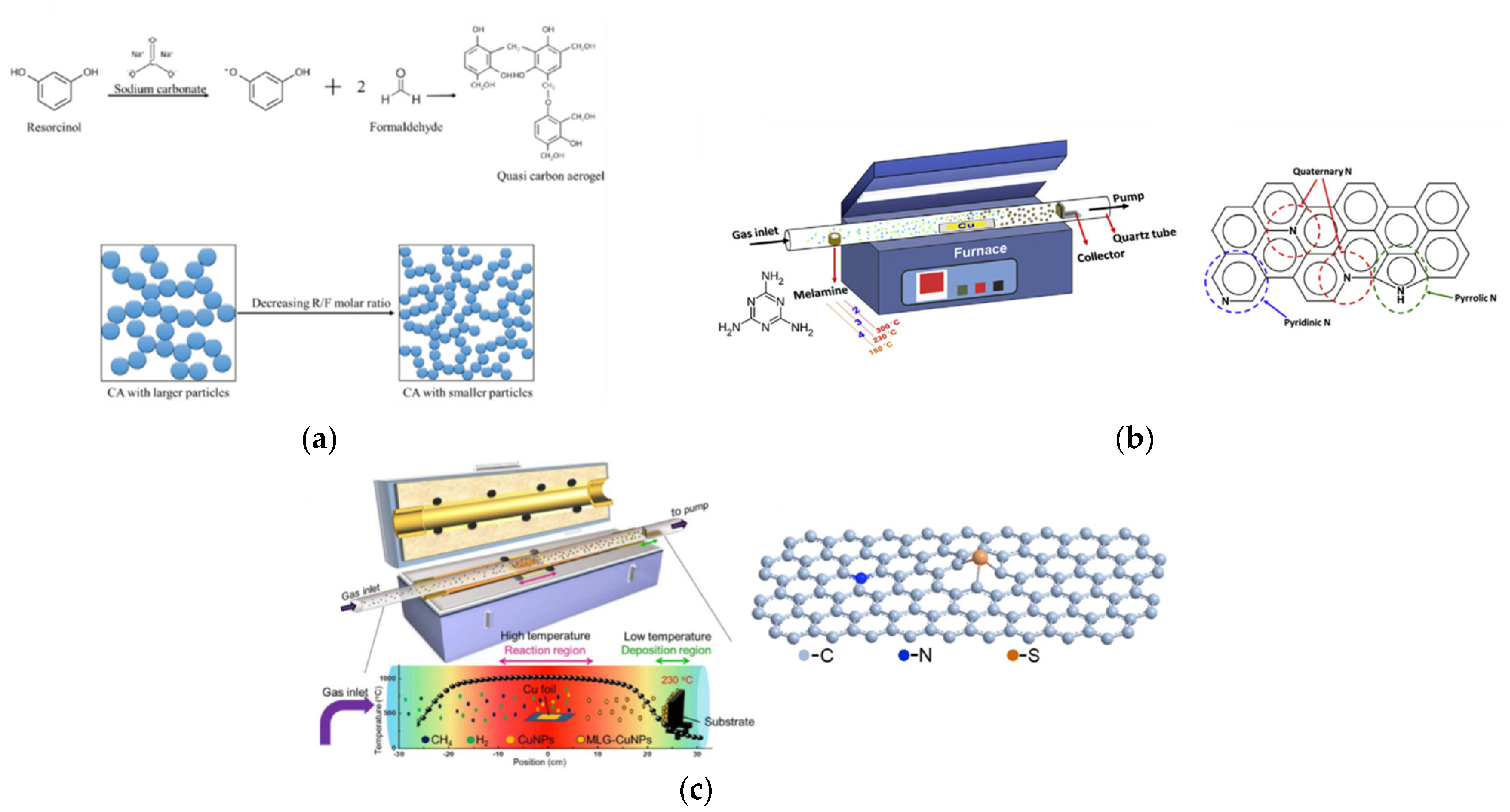
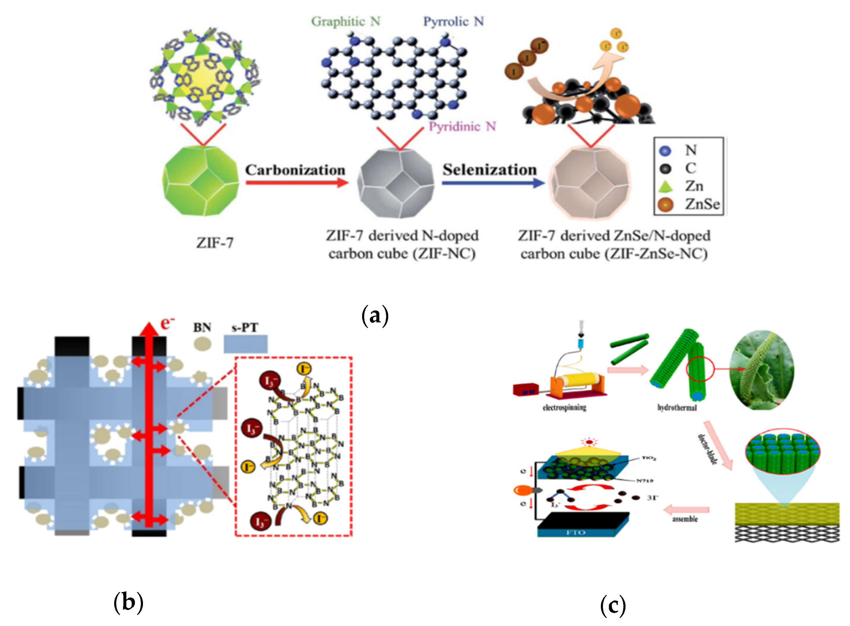
Jian et al. produced the ZnSe/N doped carbon (ZIF-ZnSe-NC) cube hybrid electrocatalyst derived from zeolitic imidazolate framework by carbonization and selenization, as shown in
Figure 10a [
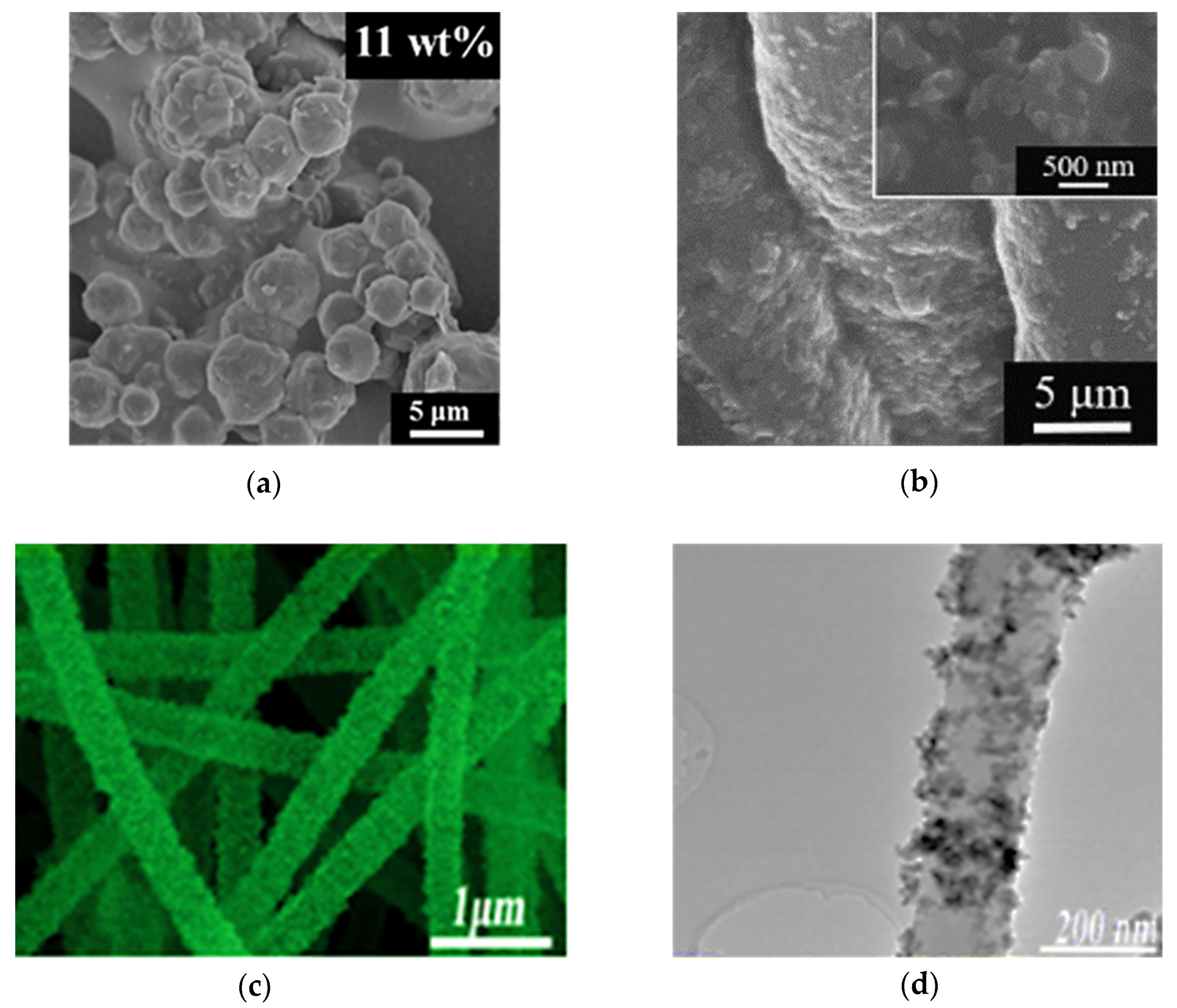
86]. The particle size of the ZIF-ZnSe-NC-11 wt% was ~3–6 μm, as shown in
Figure 11a. ZIF-ZnSe-NC-11 wt% had the best performance compared to the ZIF-7 (5.27%), the ZIF-7-NC (6.02%), the ZIF-ZnSe-NC-11 wt% (8.69%), and the Pt (8.26%), as shown in
Table 7. Furthermore, the ZIF-ZnSe-NC-11 wt% showed
η of 7.99%, 8.02%, and 8.69% under 10, 50 and 100 mW cm
−2 illumination, respectively, as shown in
Table 7. For electrochemical properties (
Table 8), the ZIF-ZnSe-NC-11 wt% could offer a
Jpc that was larger (0.91 mA cm
−2) and a
Rct-EIS that was lower (1.26 Ω cm
2) than the Pt (
Jpc of 0.85 mA cm
−2 and
Rct-EIS of 1.71 Ω cm
2). In this study, the good performance of the DSSCs is contributed to (1) the excellent electrocatalytic properties of ZnSe, (2) more active sites induced by N-doped carbons, and (3) the electrocatalytic ability enhanced by ZIF-7.
Table 7.
The photovoltaic parameters of various conductive polymer material-based CEs in the DSSC with an I−/I3− redox couple and N719 dye are compared under simulated solar light conditions.
Table 7.
The photovoltaic parameters of various conductive polymer material-based CEs in the DSSC with an I−/I3− redox couple and N719 dye are compared under simulated solar light conditions.
| Sample | η (%) | η of Pt (%) | JSC (mA cm−2) | VOC (V) | FF | Pin (mW cm−2) | Ref. |
|---|
| ZIF-ZnSe-NC-11 wt% | 8.69 | 8.26 | 16.40 | 0.77 | 0.69 | 100 | [86] |
| 8.02 | 7.87 | 7.60 | 0.73 | 0.72 | 50 |
| 7.99 | 7.41 | 1.63 | 0.68 | 0.72 | 10 |
| BN/s-PT-50 | 9.21 | 8.11 | 16.59 | 0.78 | 0.71 | 100 | [87] |
| Fe3O4/Ni@N-RGO | 8.96 | 7.87 | 16.50 | 0.78 | 0.70 | 100 | [88] |
| Bi2MoO6/CNFs | 9.02 | 7.47 | 14.78 | 0.84 | 0.73 | 100 | [89] |
Table 8.
The electrochemical parameters of various hybrid compound electrocatalysts measured in the I−/I3−-based electrolyte.
Table 8.
The electrochemical parameters of various hybrid compound electrocatalysts measured in the I−/I3−-based electrolyte.
| Sample | Jpc (mA cm−2) | ΔEp (V) | Rct-EIS (Ω cm2) | Ref. |
|---|
| MOF-525/s-PT-3 | 2.03 | 0.61 | 1.42 | [29] |
| ZIF-ZnSe-NC-11 wt% | 0.91 | 0.52 | 1.26 | [86] |
| BN/s-PT-50 | 6.88 | 0.68 | 1.06 | [87] |
| Fe3O4/Ni@N-RGO | 4.44 | 0.19 | 0.16 | [88] |
| Bi2MoO6/CNFs | 3.03 | 0.44 | 0.61 | [89] |
Figure 10.
(
a) The sketch of the process from ZIF-7 to ZIF-derived materials [
86]. (
b) Sketch of the electron transfer phenomenon in BN/s-PT-50 electrode [
87]. (
c) The fabrication process of a dye-sensitized solar cells with the Bi
2MoO
6/CNFs composite [
89].
Figure 10.
(
a) The sketch of the process from ZIF-7 to ZIF-derived materials [
86]. (
b) Sketch of the electron transfer phenomenon in BN/s-PT-50 electrode [
87]. (
c) The fabrication process of a dye-sensitized solar cells with the Bi
2MoO
6/CNFs composite [
89].
Figure 11.
SEM images of (
a) ZIF-ZnSe-NC-11 wt% [
86], (
b) BN/s-PT-50 [
87], and (
c) Bi
2MoO6/CNFs [
89]. (
d) The TEM image of Bi
2MoO
6/CNFs [
89].
Figure 11.
SEM images of (
a) ZIF-ZnSe-NC-11 wt% [
86], (
b) BN/s-PT-50 [
87], and (
c) Bi
2MoO6/CNFs [
89]. (
d) The TEM image of Bi
2MoO
6/CNFs [
89].
Chen et al. obtained a boron nitride/sulfonated poly(thiophene-3-[2-(2-methoxyethoxy)ethoxy]-2,5-diyl) (denoted as BN/s-PT) composite electrocatalyst by means of physical mixing [
87]. The BN/s-PT-30, BN/s-PT-40, BN/s-PT-50, BN/s-PT-60, and BN/s-PT-70 contained the BN/s-PT with a weight percentage of 30, 40, 50, 60, and 70, respectively. The SEM images (
Figure 11b) of the BN/s-PT-50 show the BN nanoparticles (500 nm) covered by the s-PT polymer. BN/s-PT-50 shows the best
η of 9.21% compared to the BN/s-PT-30 (7.46%), the BN/s-PT-40 (8.26%), the BN/s-PT-60 (8.22%), the BN/s-PT-70 (7.02%) and the Pt (8.11%), as shown in
Table 7. Moreover, as the BN/s-PT-50 was operated in an indoor environment, the
η was 21.02%, 19.52%, and 17.48% at 1.94 (6000), 0.98 (3000), and 0.33 mW cm
−2 (1000 lux), respectively. As shown in
Table 8, BN/s-PT-50 exhibited the best electrocatalytic properties (
Jpc of 6.88 mA cm
−2 and
Rct-EIS of 1.06 Ω cm
2). In this study, BN offered more active sites for electrochemical reactions, and s-PT supported adhesion and conducting, as shown in
Figure 10b.
Xu et al. acquired Fe
3O
4/Ni@N-RGO nanoflowers from the hydrothermal method [
88]. The Fe
3O
4/Ni@N-RGO nanoflowers show an average size of about 2 μm and thin nanoflakes with numerous pores. The
η (8.96%) of Fe
3O
4/Ni@N-RGO was better than Fe
3O
4 (7.92%), Fe
3O
4/Ni (8.25%), Fe
3O
4/Ni@RGO (8.53%), and Pt (7.87%), as shown in
Table 7. For electrochemical properties, the
Jpc (4.44 mA cm
−2 )and
Rct-EIS (0.16 Ω cm
2) of Fe
3O
4/Ni@N-RGO were also better than Fe
3O
4 (3.02 mA cm
−2 and
Rct-EIS of 0.49 Ω cm
2), Fe
3O
4/Ni (3.23 mA cm
−2 and
Rct-EIS of 0.21 Ω cm
2), Fe
3O
4/Ni@RGO (4.02 mA cm
−2 and
Rct-EIS of 0.17 Ω cm
2), and Pt (2.81 mA cm
−2 and
Rct-EIS of 0.51 Ω cm
2), as shown in
Table 8, indicating the better electrocatalytic properties. The DSSC performance could be improved by (1) the more reaction areas and electron pathways offered by hierarchical porous Fe
3O
4 nanoflowers decorated with Ni nanoparticles and RGO nanosheets, (2) more active sites provided by heteroatoms embedded into graphene oxide, and (3) the excellent electrocatalytic properties of Fe
3O
4, Ni, and RGO.
Li et al. prepared the carbon nanofibers supported Bi
2MoO
6 nanosheets (Bi
2MoO
6/CNFs) by electrospinning and hydrothermal methods, as shown in
Figure 10c [
89]. The thickness of Bi
2MoO
6 nanosheets was 10–20 nm, and the diameter of the CNFs was 400–500 nm, as shown in
Figure 11c,d. Moreover, the specific surface of Bi
2MoO
6/CNFs and the CNFs were 32.81 and 18.82 m
2 g
−1, respectively. The Bi
2MoO
6/CNFs exhibited the best performance compared to the Bi
2MoO
6/CNFs (9.02%), the CNFs (7.48%), and the Pt (7.487%), as shown in
Table 7. According to
Table 8, the
Jpc (3.03 mA cm
−2) and
Rct-EIS (0.61 Ω cm
2) of Bi
2MoO
6/CNFs are better than the CNFs (2.76 mA cm
−2 and
Rct-EIS of 1.31 Ω cm
2), and the Pt (2.00 mA cm
−2 and
Rct-EIS of 2.32 Ω cm
2). These results reveal that Bi
2MoO
6 provides more active sites and that CNFs support better electrical conductivity for better DSSC performance.
In this hybrid compound electro-catalyst section, the strategies for improving DSSC performance can be summarized as follows: (1) selecting large surface area materials, (2) using a facilitating conducting material, (3) assembling composite materials, and (4) designing specific morphology. Accordingly, the as-fabricated DSSCs could hold promise for applications under dim light or various weather conditions as well as in indoor environments.
A brief summary of this section follows: Jian et al. proposed a new concept for preparing a ZnSe/N-doped carbon cube hybrid electrocatalyst via the carbonization and selenization of ZIF-7 (i.e., zeolitic imidazolate framework) for the first time, where the N-doped carbon cube is beneficial to the electrocatalytic performance and the electrical conductivity, and the embedded ZnSe in the carbon matrix serves as the additional active site for facilitating I3− reduction. Chen et al. prepared the BN/s-PT composite electrocatalyst for a Pt-free DSSC, obtaining a significantly enhanced cell efficiency. This achievement is due to the synergetic effect of the BN nanoparticle and the s-PT binder; the former offered a large active surface area and a high intrinsic heterogeneous rate constant, and the latter formed fast electron transfer matrices. Xu et al. designed and synthesized a novel nanostructured composite electro-catalyst (i.e., three-component composite) that consisted of hierarchical porous Fe3O4 nanoflowers decorated with Ni nanoparticles and wrapped with N-doped reduced graphene oxide nanosheets (denoted Fe3O4/Ni@N-RGO), where the hierarchically nanostructure of flower-like Fe3O4 could offer a 3D porous scaffold with a large specific surface area for loading Ni nanoparticles and N-doped graphene nanosheets; thus, the as-obtained Fe3O4/Ni@N-RGO composite can afford high catalytic activity, excellent electrical conductivity, and abundant nanopores to interact with the I3− ions. Li et al. successfully prepared Bi2MoO6/CNFs composites by electrospinning and hydrothermal methods, where the carbon material (i.e., CNFs) had good electrical conductivity and where the transition metal oxides (i.e., Bi2MoO6) could provide more active sites for better catalytic performance. Finally, the DSSCs with the above hybrid compound-based CEs exhibited superior cell performance than that of the cell with a Pt electrode.


