
Multi-Walled Carbon Nanotube-Assisted Encapsulation Approach for Stable Perovskite Solar Cells


 ,
,  and
and
Abstract
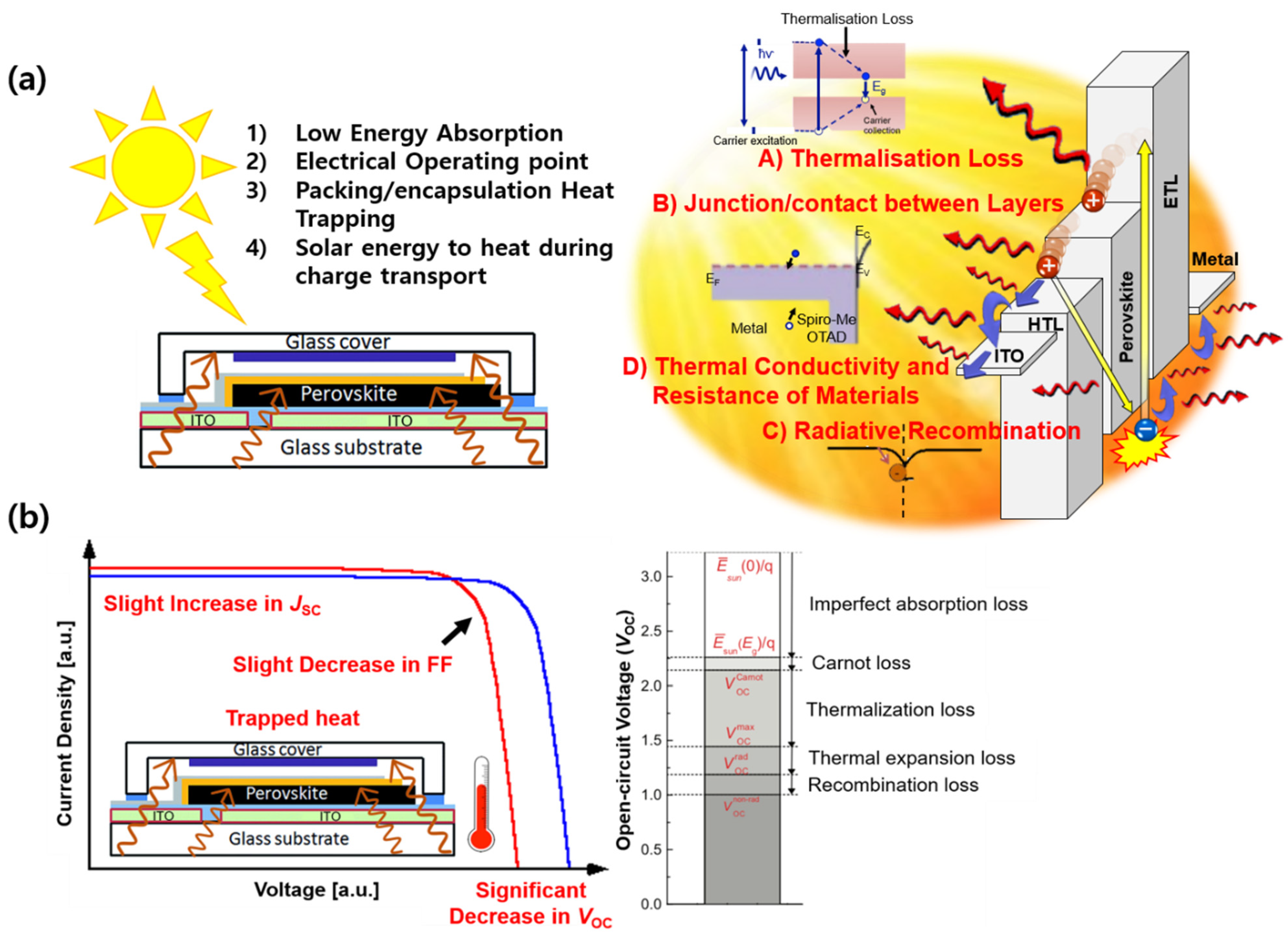
:1. Introduction
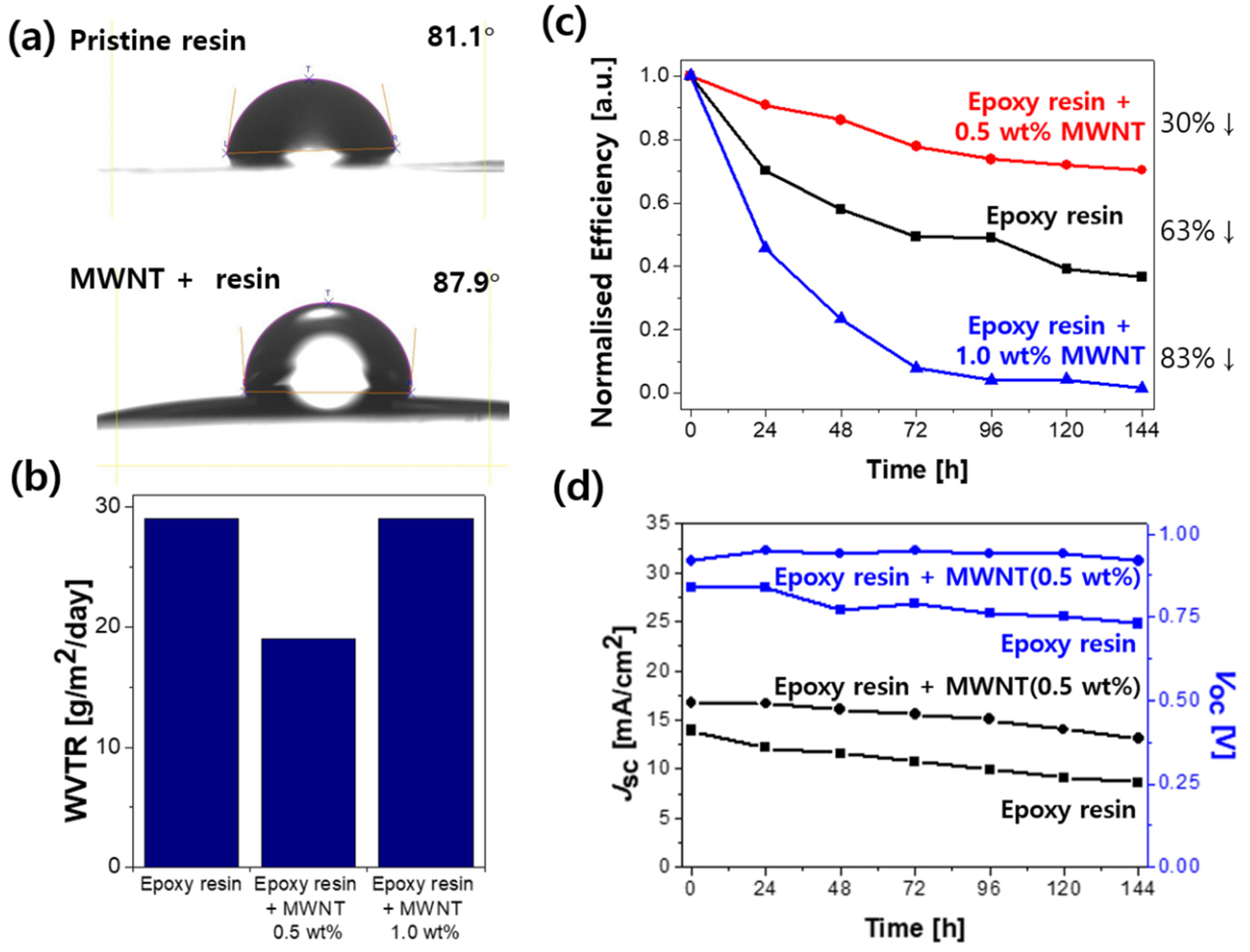
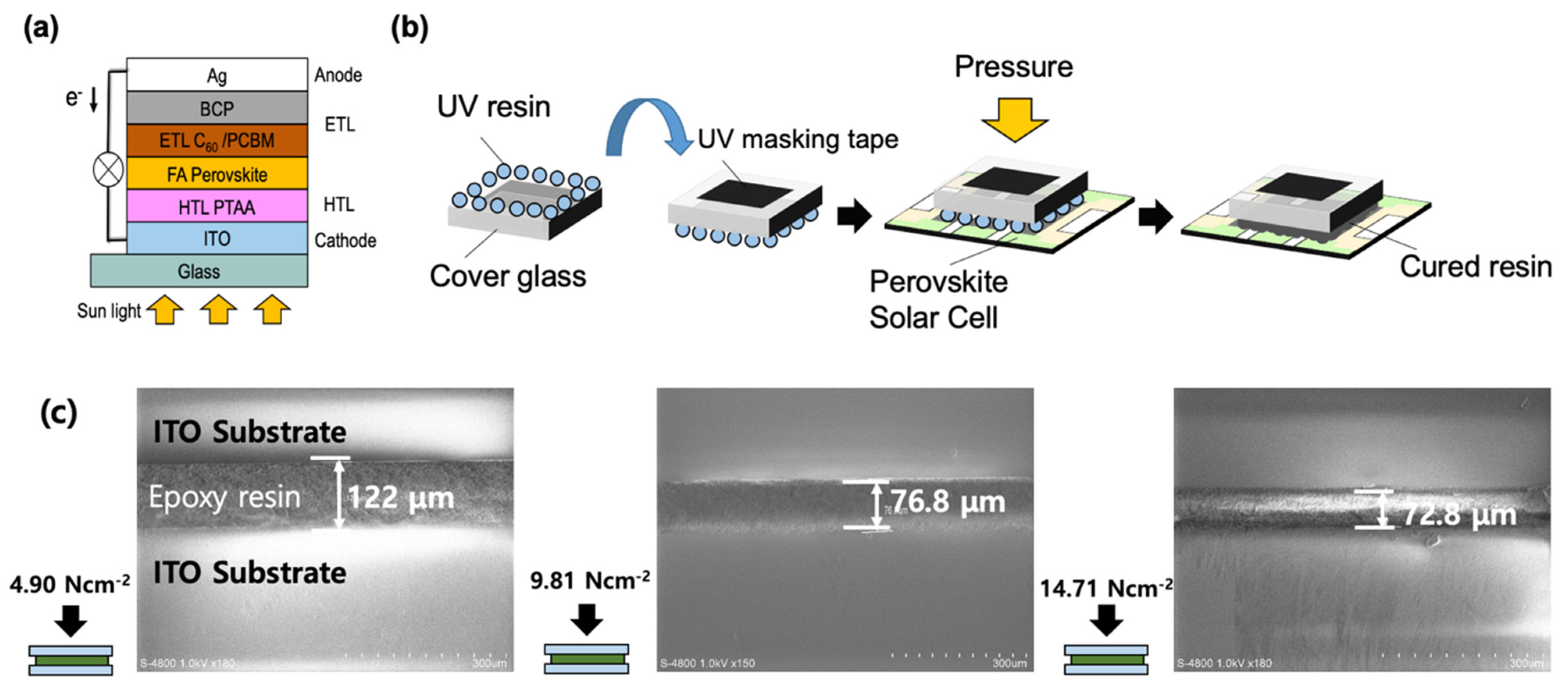
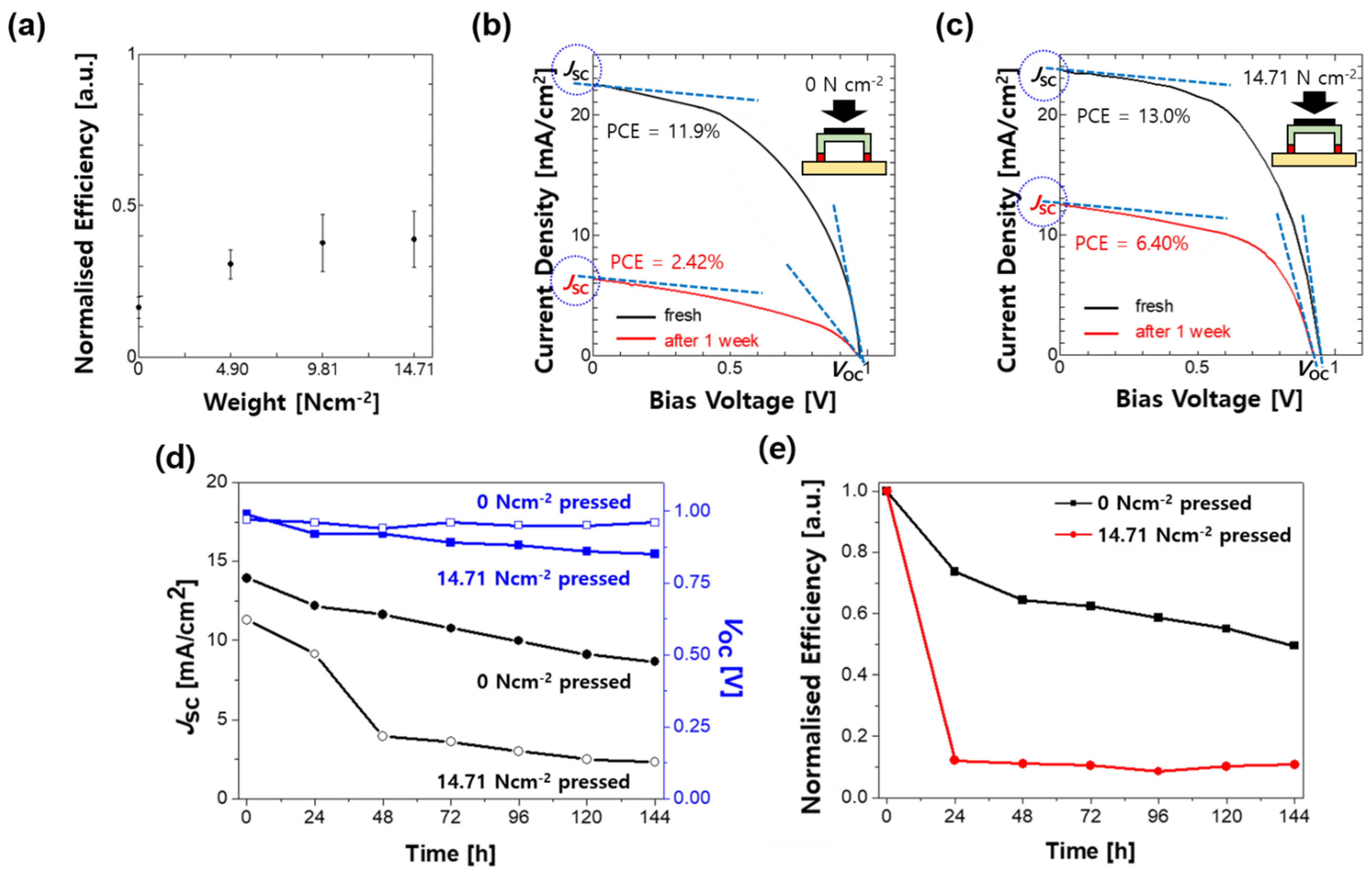
2. Results and Discussion
3. Materials and Methods
3.1. PSC Fabrication
3.2. Encapsulant
3.3. Characterisations
4. Conclusions
Supplementary Materials
Author Contributions
Funding
Institutional Review Board Statement
Informed Consent Statement
Data Availability Statement
Acknowledgments
Conflicts of Interest
Sample Availability
References
- Boix, P.P.; Nonomura, K.; Mathews, N.; Mhaisalkar, S.G. Current progress and future perspectives for organic/inorganic perovskite solar cells. Mater. Today 2014, 17, 16–23. [Google Scholar] [CrossRef]
- Yang, Q.; Dettori, R.; Yuan, G.; Anderson, L.R. A perovskite solar cell owing very high stabilities and power conversion efficiencies. Sol. Energy 2020, 201, 541–546. [Google Scholar] [CrossRef]
- Lee, C.; Lee, S.W.; Bae, S.; Shawky, A.; Devaraj, V.; Anisimov, A.; Kauppinen, E.I.; Oh, J.W.; Kang, Y.; Kim, D.; et al. Carbon Nanotube Electrode-Based Perovskite–Silicon Tandem Solar Cells. Sol. RRL 2020, 4, 2000353. [Google Scholar] [CrossRef]
- Xing, G.; Mathews, N.; Lim, S.S.; Lam, Y.M.; Mhaisalkar, S.; Sum, T.C. Long-Range Balanced Electron- and Hole-Transport Lengths in Organic-Inorganic CH3NH3PbI3. Science 2013, 342, 344–347. [Google Scholar] [CrossRef]
- Thote, A.; Jeon, I.; Lin, H.S.; Manzhos, S.; Nakagawa, T.; Suh, D.; Hwang, J.; Kashiwagi, M.; Shiomi, J.; Maruyama, S.; et al. High-Working-Pressure Sputtering of ZnO for Stable and Efficient Perovskite Solar Cells. ACS Appl. Electron. Mater. 2019, 1, 389–396. [Google Scholar] [CrossRef]
- Jeon, I.; Shawky, A.; Lin, H.S.; Seo, S.; Okada, H.; Lee, J.W.; Pal, A.; Tan, S.; Anisimov, A.; Kauppinen, E.I.; et al. Controlled Redox of Lithium-Ion Endohedral Fullerene for Efficient and Stable Metal Electrode-Free Perovskite Solar Cells. J. Am. Chem. Soc. 2019, 141, 16553–16558. [Google Scholar] [CrossRef] [PubMed]
- Jeon, I.; Ueno, H.; Seo, S.; Aitola, K.; Nishikubo, R.; Saeki, A.; Okada, H.; Boschloo, G.; Maruyama, S.; Matsuo, Y. Lithium-Ion Endohedral Fullerene (Li+@C60) Dopants in Stable Perovskite Solar Cells Induce Instant Doping and Anti-Oxidation. Angew. Chem. Int. Ed. 2018, 57, 4607–4611. [Google Scholar] [CrossRef] [PubMed]
- Ahn, N.; Kwak, K.; Jang, M.S.; Yoon, H.; Lee, B.Y.; Lee, J.K.; Pikhitsa, P.V.; Byun, J.; Choi, M. Trapped charge-driven degradation of perovskite solar cells. Nat. Commun. 2016, 7, 13422. [Google Scholar] [CrossRef] [PubMed] [Green Version]
- Ahn, N.; Jeon, I.; Yoon, J.; Kauppinen, E.I.; Matsuo, Y.; Maruyama, S.; Choi, M. Carbon-sandwiched perovskite solar cell. J. Mater. Chem. A 2018, 6, 1382–1389. [Google Scholar] [CrossRef]
- Jena, A.K.; Numata, Y.; Ikegami, M.; Miyasaka, T. Role of spiro-OMeTAD in performance deterioration of perovskite solar cells at high temperature and reuse of the perovskite films to avoid Pb-waste. J. Mater. Chem. A 2018, 6, 2219–2230. [Google Scholar] [CrossRef]
- Lin, H.S.; Jeon, I.; Xiang, R.; Seo, S.; Lee, J.W.; Li, C.; Pal, A.; Manzhos, S.; Goorsky, M.S.; Yang, Y.; et al. Achieving High Efficiency in Solution-Processed Perovskite Solar Cells Using C60/C70 Mixed Fullerenes. ACS Appl. Mater. Interfaces 2018, 10, 39590–39598. [Google Scholar] [CrossRef] [PubMed]
- Conings, B.; Drijkoningen, J.; Gauquelin, N.; Babayigit, A.; D’Haen, J.; D’Olieslaeger, L.; Ethirajan, A.; Verbeeck, J.; Manca, J.; Mosconi, E.; et al. Intrinsic Thermal Instability of Methylammonium Lead Trihalide Perovskite. Adv. Energy Mater. 2015, 5, 1500477. [Google Scholar] [CrossRef]
- Norrman, K.; Madsen, M.V.; Gevorgyan, S.A.; Krebs, F.C. Degradation patterns in water and oxygen of an inverted polymer solar cell. J. Am. Chem. Soc. 2010, 132, 16883–16892. [Google Scholar] [CrossRef] [PubMed]
- Adams, J.; Spyropoulos, G.D.; Salvador, M.; Li, N.; Strohm, S.; Lucera, L.; Langner, S.; MacHui, F.; Zhang, H.; Ameri, T.; et al. Air-processed organic tandem solar cells on glass: Toward competitive operating lifetimes. Energy Environ. Sci. 2015, 8, 169–176. [Google Scholar] [CrossRef] [Green Version]
- Adams, J.; Salvador, M.; Lucera, L.; Langner, S.; Spyropoulos, G.D.; Fecher, F.W.; Voigt, M.M.; Dowland, S.A.; Osvet, A.; Egelhaaf, H.J.; et al. Water ingress in encapsulated inverted organic solar cells: Correlating infrared imaging and photovoltaic performance. Adv. Energy Mater. 2015, 5, 1501065. [Google Scholar] [CrossRef]
- Burrows, P.E.; Bulovic, V.; Forrest, S.R.; Sapochak, L.S.; McCarty, D.M.; Thompson, M.E. Reliability and degradation of organic light emitting devices. Appl. Phys. Lett. 1994, 65, 2922–2924. [Google Scholar] [CrossRef]
- Roesch, R.; Eberhardt, K.R.; Engmann, S.; Gobsch, G.; Hoppe, H. Polymer solar cells with enhanced lifetime by improved electrode stability and sealing. Sol. Energy Mater. Sol. Cells 2013, 117, 59–66. [Google Scholar] [CrossRef]
- Hösel, M.; Søndergaard, R.R.; Jørgensen, M.; Krebs, F.C. Comparison of UV-curing, hotmelt, and pressure sensitive adhesive as roll-to-roll encapsulation methods for polymer solar cells. Adv. Eng. Mater. 2013, 15, 1068–1075. [Google Scholar] [CrossRef]
- Roppolo, I.; Shahzad, N.; Sacco, A.; Tresso, E.; Sangermano, M. Multifunctional NIR-reflective and self-cleaning UV-cured coating for solar cell applications based on cycloaliphatic epoxy resin. Prog. Org. Coat. 2014, 77, 458–462. [Google Scholar] [CrossRef]
- Abd-Elnaiem, A.M.; Hussein, S.I.; Assaedi, H.S.; Mebed, A.M. Fabrication and evaluation of structural, thermal, mechanical and optical behavior of epoxy–TEOS/MWCNTs composites for solar cell covering. Polym. Bull. 2021, 78, 3995–4017. [Google Scholar] [CrossRef]
- Iijima, S. Helical microtubules of graphitic carbon. Nature 1991, 354, 56–58. [Google Scholar] [CrossRef]
- Jeon, I.; Matsuo, Y.; Maruyama, S. Single-Walled Carbon Nanotubes in Solar Cells. Top. Curr. Chem. 2018, 376, 4. [Google Scholar] [CrossRef]
- Jeon, I.; Xiang, R.; Shawky, A.; Matsuo, Y.; Maruyama, S. Single-Walled Carbon Nanotubes in Emerging Solar Cells: Synthesis and Electrode Applications. Adv. Energy Mater. 2019, 9, 1801312. [Google Scholar] [CrossRef]
- Könemann, F.; Vollmann, M.; Wagner, T.; Mohd Ghazali, N.; Yamaguchi, T.; Stemmer, A.; Ishibashi, K.; Gotsmann, B. Thermal Conductivity of a Supported Multiwalled Carbon Nanotube. J. Phys. Chem. C 2019, 123, 12460–12465. [Google Scholar] [CrossRef] [Green Version]
- Kumanek, B.; Janas, D. Thermal conductivity of carbon nanotube networks: A review. J. Mater. Sci. 2019, 54, 7397–7427. [Google Scholar] [CrossRef] [Green Version]
- Moisala, A.; Li, Q.; Kinloch, I.A.; Windle, A.H. Thermal and electrical conductivity of single- and multi-walled carbon nanotube-epoxy composites. Compos. Sci. Technol. 2006, 66, 1285–1288. [Google Scholar] [CrossRef]
- Kakade, B.A.; Pillai, V.K. Tuning the wetting properties of multiwalled carbon nanotubes by surface functionalization. J. Phys. Chem. C 2008, 112, 3183–3186. [Google Scholar] [CrossRef]
- Yang, W.; Zhong, D.; Shi, M.; Qu, S.; Chen, H. Toward Highly Thermal Stable Perovskite Solar Cells by Rational Design of Interfacial Layer. iScience 2019, 22, 534–543. [Google Scholar] [CrossRef] [PubMed] [Green Version]
- Dao, Q.D.; Tsuji, R.; Fujii, A.; Ozaki, M. Study on degradation mechanism of perovskite solar cell and their recovering effects by introducing CH3NH3I layers. Org. Electron. 2017, 43, 229–234. [Google Scholar] [CrossRef]
- Shirayama, M.; Kato, M.; Miyadera, T.; Sugita, T.; Fujiseki, T.; Hara, S.; Kadowaki, H.; Murata, D.; Chikamatsu, M.; Fujiwara, H. Degradation mechanism of CH3NH3PbI3 perovskite materials upon exposure to humid air. J. Appl. Phys. 2016, 119, 115501. [Google Scholar] [CrossRef] [Green Version]
- Raga, S.R.; Jung, M.C.; Lee, M.V.; Leyden, M.R.; Kato, Y.; Qi, Y. Influence of air annealing on high efficiency planar structure perovskite solar cells. Chem. Mater. 2015, 27, 1597–1603. [Google Scholar] [CrossRef]
- Niu, G.; Li, W.; Meng, F.; Wang, L.; Dong, H.; Qiu, Y. Study on the stability of CH3NH3PbI3 films and the effect of post-modification by aluminum oxide in all-solid-state hybrid solar cells. J. Mater. Chem. A 2014, 2, 705–710. [Google Scholar] [CrossRef]
- Dou, Y.; Xu, H.; Liu, Y.; Wang, M.; Zhang, J.; Ovchinnikova, O.S.; Hu, B. Tuning spin-orbit coupling towards enhancing photocurrent in hybrid organic-inorganic perovskites by using mixed organic cations. Org. Electron. 2020, 81, 105671. [Google Scholar] [CrossRef]
- Boyd, C.C.; Cheacharoen, R.; Leijtens, T.; McGehee, M.D. Understanding Degradation Mechanisms and Improving Stability of Perovskite Photovoltaics. Chem. Rev. 2019, 119, 3418–3451. [Google Scholar] [CrossRef]
- Jeon, I.; Chiba, T.; Delacou, C.; Guo, Y.; Kaskela, A.; Reynaud, O.; Kauppinen, E.I.; Maruyama, S.; Matsuo, Y. Single-Walled Carbon Nanotube Film as Electrode in Indium-Free Planar Heterojunction Perovskite Solar Cells: Investigation of Electron-Blocking Layers and Dopants. Nano Lett. 2015, 15, 6665–6671. [Google Scholar] [CrossRef]
- Jeon, I.; Nakao, S.; Hirose, Y.; Hasegawa, T.; Matsuo, Y. Indium-Free Inverted Organic Solar Cells Using Niobium-Doped Titanium Oxide with Integrated Dual Function of Transparent Electrode and Electron Transport Layer. Adv. Electron. Mater. 2016, 2, 2–7. [Google Scholar] [CrossRef]
- Ava, T.T.; Al Mamun, A.; Marsillac, S.; Namkoong, G. A review: Thermal stability of methylammonium lead halide based perovskite solar cells. Appl. Sci. 2019, 9, 188. [Google Scholar] [CrossRef] [Green Version]
- Rau, U.; Paetzold, U.W.; Kirchartz, T. Thermodynamics of light management in photovoltaic devices. Phys. Rev. B 2014, 90, 035211. [Google Scholar] [CrossRef] [Green Version]
- Mehdizadeh-Rad, H.; Singh, J. Influence of interfacial traps on the operating temperature of perovskite solar cells. Materials 2019, 12, 2727. [Google Scholar] [CrossRef] [Green Version]
- Reyna, Y.; Salado, M.; Kazim, S.; Pérez-Tomas, A.; Ahmad, S.; Lira-Cantu, M. Performance and stability of mixed FAPbI3(0.85)MAPbBr3(0.15) halide perovskite solar cells under outdoor conditions and the effect of low light irradiation. Nano Energy 2016, 30, 570–579. [Google Scholar] [CrossRef] [Green Version]
- Park, J.G.; Cheng, Q.; Lu, J.; Bao, J.; Li, S.; Tian, Y.; Liang, Z.; Zhang, C.; Wang, B. Thermal conductivity of MWCNT/epoxy composites: The effects of length, alignment and functionalization. Carbon 2021, 50, 2083–2090. [Google Scholar] [CrossRef]
- Huang, C.; Zhen, W.; Huang, Z.; Luo, D. Thermal and electrical conductivities of epoxy resin-based composites incorporated with carbon nanotubes and TiO2 for a thermoelectric application. Appl. Phys. A 2018, 124, 38. [Google Scholar] [CrossRef]
- Green, M.A.; Emery, K.; Hishikawa, Y.; Warta, W.; Dunlop, E.D. Solar cell efficiency tables (version 40). Prog. Photovolt. Res. Appl. 2012, 20, 606–614. [Google Scholar] [CrossRef]
- Polman, A.; Atwater, H.A. Photonic design principles for ultrahigh-efficiency photovoltaics. Nat. Mater. 2012, 11, 174–177. [Google Scholar] [CrossRef]
- Choi, K.; Lee, J.; Kim, H.I.; Park, C.W.; Kim, G.W.; Choi, H.; Park, S.; Park, S.A.; Park, T. Thermally stable, planar hybrid perovskite solar cells with high efficiency. Energy Environ. Sci. 2018, 11, 3238–3247. [Google Scholar] [CrossRef]
- Youssry, M.; Al-Ruwaidhi, M.; Zakeri, M.; Zakeri, M. Physical functionalization of multi-walled carbon nanotubes for enhanced dispersibility in aqueous medium. Emerg. Mater. 2020, 3, 25–32. [Google Scholar] [CrossRef] [Green Version]
- Pérez, E.M.; Martín, N. π-π interactions in carbon nanostructures. Chem. Soc. Rev. 2015, 44, 6425–6433. [Google Scholar] [CrossRef]
- Grimme, S. Do special noncovalent π-π stacking interactions really exist? Angew. Chem. Int. Ed. 2008, 47, 3430–3434. [Google Scholar] [CrossRef]
- Yang, Q.S.; He, X.Q.; Liu, X.; Leng, F.F.; Mai, Y.W. The effective properties and local aggregation effect of CNT/SMP composites. Compos. Part B Eng. 2012, 43, 33–38. [Google Scholar] [CrossRef]
- Nguyen, T.; Petersen, E.J.; Pellegrin, B.; Gorham, J.M.; Lam, T.; Zhao, M.; Sung, L. Impact of UV irradiation on multiwall carbon nanotubes in nanocomposites: Formation of entangled surface layer and mechanisms of release resistance. Carbon 2017, 116, 191–200. [Google Scholar] [CrossRef] [PubMed] [Green Version]
- Dembele, K.T.; Selopal, G.S.; Soldano, C.; Nechache, R.; Rimada, J.C.; Concina, I.; Sberveglieri, G.; Rosei, F.; Vomiero, A. Hybrid Carbon Nanotubes–TiO2 Photoanodes for High Efficiency Dye-Sensitized Solar Cells. J. Phys. Chem. C 2013, 117, 14510–14517. [Google Scholar] [CrossRef]
- Mohammadnezhad, M.; Selopal, G.S.; Wang, Z.M.; Stansfield, B.; Zhao, H.; Rosei, F. Role of Carbon Nanotubes to Enhance the Long-Term Stability of Dye-Sensitized Solar Cells. ACS Photonics 2020, 7, 653–664. [Google Scholar] [CrossRef]
- Mohammadnezhad, M.; Selopal, G.S.; Wang, Z.M.; Stansfield, B.; Zhao, H.; Rosei, F. Towards Long-Term Thermal Stability of Dye-Sensitized Solar Cells Using Multiwalled Carbon Nanotubes. ChemPlusChem 2018, 83, 682–690. [Google Scholar] [CrossRef] [PubMed]


| Device Type\Device Performance | JSC [mA/cm2] | VOC [V] | FF | PCE [%] | |
|---|---|---|---|---|---|
| Feature | Stability Time | ||||
| Before encapsulation | N/A | 19.4 | 0.94 | 64.8 | 11.8 |
| Encapsulation by 4.90 N cm−2 pressure | Initial | 11.3 | 0.97 | 28.67 | 3.15 |
| one week | 2.31 | 0.96 | 15.33 | 0.34 | |
| Encapsulation by 14.71 N cm−2 pressure | Initial | 13.9 | 0.99 | 28.69 | 3.96 |
| one week | 8.63 | 0.85 | 26.72 | 1.96 | |
| Encapsulation with MWNT (0.5 wt%)-added epoxy resin | Initial | 16.7 | 0.92 | 61.90 | 9.51 |
| one week | 13.1 | 0.92 | 55.51 | 6.69 | |
| Encapsulation with MWNT (1.0 wt%)-added epoxy resin | Initial | 16.8 | 0.99 | 39.08 | 6.50 |
| one week | 1.19 | 0.87 | 10.62 | 0.11 | |
Publisher’s Note: MDPI stays neutral with regard to jurisdictional claims in published maps and institutional affiliations. |
© 2021 by the authors. Licensee MDPI, Basel, Switzerland. This article is an open access article distributed under the terms and conditions of the Creative Commons Attribution (CC BY) license (https://creativecommons.org/licenses/by/4.0/).
Share and Cite
Choi, J.-M.; Suko, H.; Kim, K.; Han, J.; Lee, S.; Matsuo, Y.; Maruyama, S.; Jeon, I.; Daiguji, H. Multi-Walled Carbon Nanotube-Assisted Encapsulation Approach for Stable Perovskite Solar Cells. Molecules 2021, 26, 5060. https://doi.org/10.3390/molecules26165060
Choi J-M, Suko H, Kim K, Han J, Lee S, Matsuo Y, Maruyama S, Jeon I, Daiguji H. Multi-Walled Carbon Nanotube-Assisted Encapsulation Approach for Stable Perovskite Solar Cells. Molecules. 2021; 26(16):5060. https://doi.org/10.3390/molecules26165060
Chicago/Turabian StyleChoi, Jin-Myung, Hiroki Suko, Kyusun Kim, Jiye Han, Sangsu Lee, Yutaka Matsuo, Shigeo Maruyama, Il Jeon, and Hirofumi Daiguji. 2021. "Multi-Walled Carbon Nanotube-Assisted Encapsulation Approach for Stable Perovskite Solar Cells" Molecules 26, no. 16: 5060. https://doi.org/10.3390/molecules26165060
APA StyleChoi, J.-M., Suko, H., Kim, K., Han, J., Lee, S., Matsuo, Y., Maruyama, S., Jeon, I., & Daiguji, H. (2021). Multi-Walled Carbon Nanotube-Assisted Encapsulation Approach for Stable Perovskite Solar Cells. Molecules, 26(16), 5060. https://doi.org/10.3390/molecules26165060