2.2. Space Charge Characteristics
Space charge distributions of XLPE and XLPE-g-MAH at various temperatures from 25 to 80 °C are tested with pulsed electroacoustic (PEA) method to comprehensively reveal the underlying physics of charge injections.
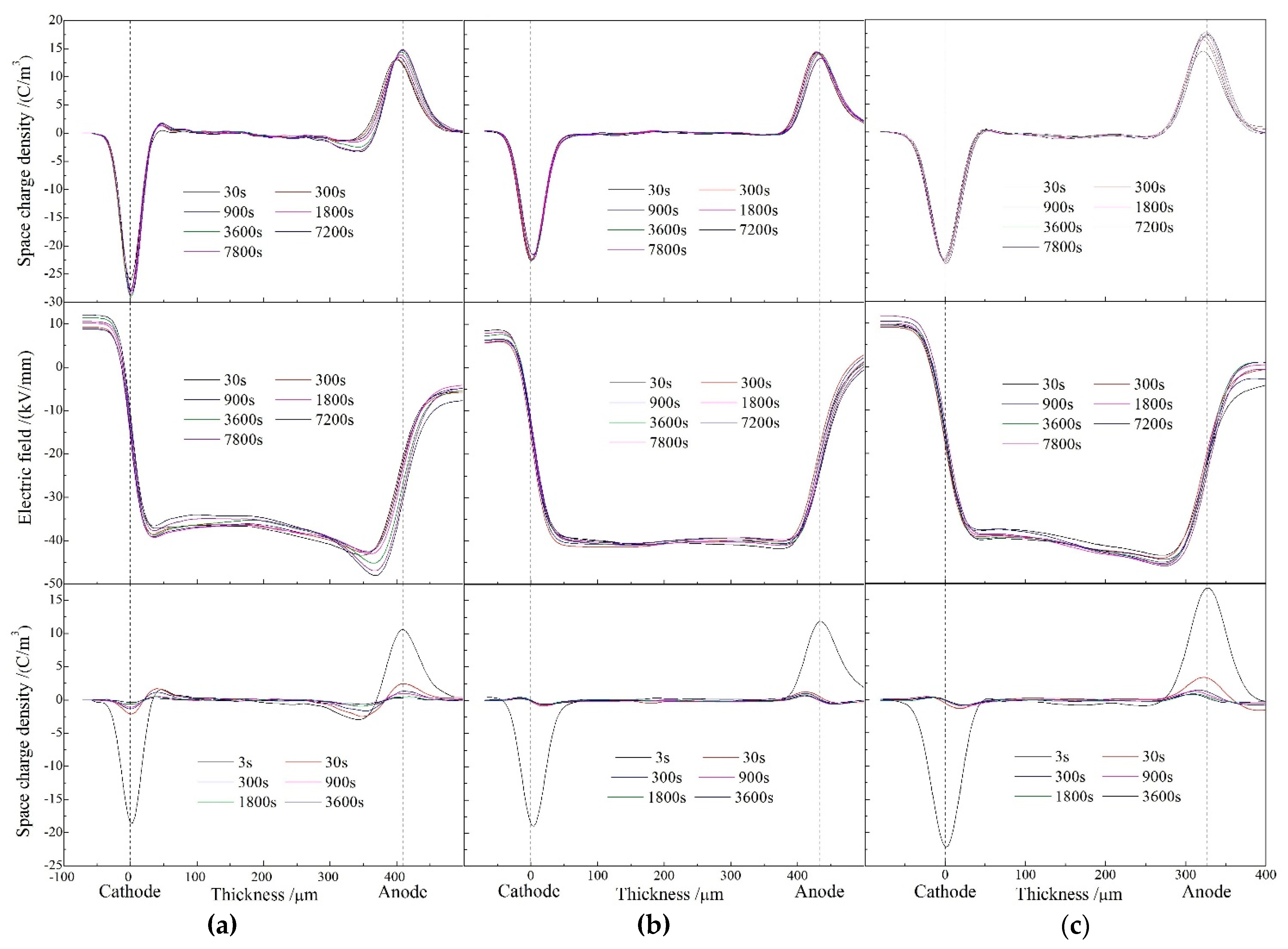
Figure 2 illustrates the space charge accumulation and dissipation under the applied DC electric field of 40 kV/mm for 130 min and then in short-circuit at the temperature of 25 °C. It is indicated from
Figure 2a that heterocharges have been evidently accumulated near both cathode and anode due to impurity ionization in pure XLPE, with the space charge density increasing with polarization time to the highest peak value of 3 C/m
3. The substantial heterocharges injected in pure XLPE strengthen the electric field near electrodes and thus exacerbate electric field distortion, as the electric field distribution across sample shown in the middle panel of
Figure 2a, implying that the peak electric field at the positive electrode approaches to 47 kV/mm. In contrast, no obvious charge injection has been found at both electrodes in XLPE-g-MAH samples even after polarizing for 130 min as shown in upper panels of
Figure 2b,c, without charge accumulation being observed in short-circuit as shown in the bottom panels. The internal electric field distortions of XLPE-g-MAH materials are alleviated with the peak electric fields being restricted below 41 and 44 kV/mm, respectively.
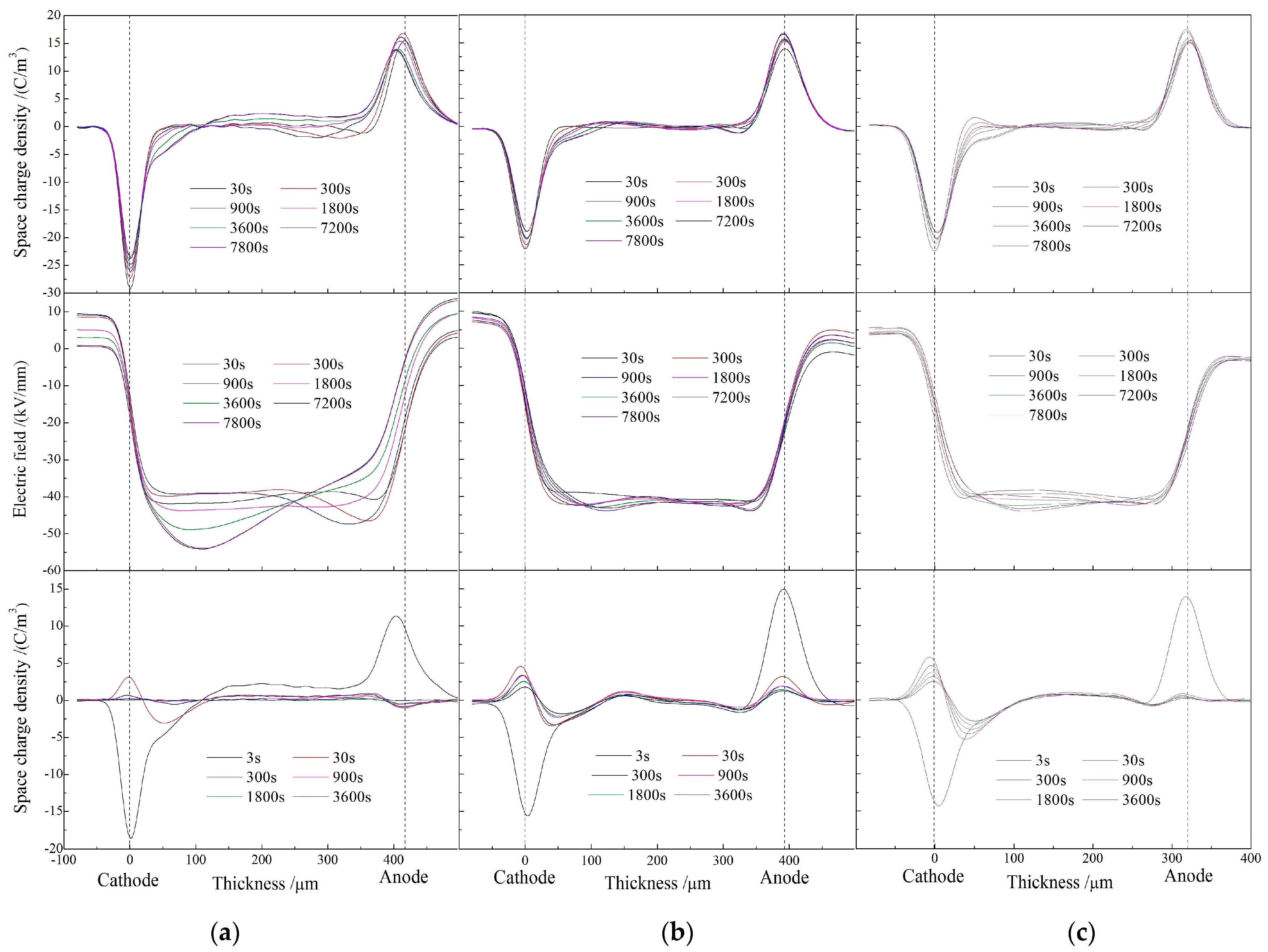
When the test temperature is raised to 60 °C, the heterocharges arise near the anode and a large number of negative homocharges also accumulate near cathode in XLPE after being polarized for 130 min, as shown in left panel of
Figure 3a. With the increase of polarization time under DC electric field, the heterocharge injection gradually transforms to the negative homocharge injection, indicating that the positive homocharges injected from anode are neutralized by the increasing negative heterocharges when the injected charges penetrate into internal region to form the positive space charge accumulations. After being short-circuit for 60 min, the homocharges are found near cathode with the peak charge density approaching to 3.14 C/m
3, while only a small amount of positive homocharges are detected near anode. The peak electric field at the negative electrode reaches to 55 kV/mm in XLPE after applying the electric field for 130 min, leading to the electric field distortion of 37.5% as shown in middle panels of
Figure 3a. Although the total charge quantity and charge density peak of the homocharges near the negative electrode in XLPE-g-0.33wt%MAH are similar to those of XLPE, the short injection distance and the minimal positive heterocharges near anode even after being polarized for 130 min verify the evident improvement in space charge characteristics of XLPE-g-MAH. Further, only the homocharges are injected near cathode for XLPE-g-0.33wt%MAH with a short injection distance of 70 μm, resulting in slightly distorted electric field of 43 kV/mm. For XLPE-g-0.41wt%MAH, a few positive heterocharges appear near cathode at the initial stage of electric polarization and then, vanish with the increasing polarization time, in contrast to the appreciable increment of homocharge injections. It is thus reasonably conjectured that positive heterocharges injected at the initial stage of applying electric field can induce negative homocharges near the cathode, leading to further increased electric field of 44 kV/mm by 20% distortion near the cathode. Complying to the Schottky injection mechanism, the homocharge injection is intensified and eventually accumulate near cathode after completely neutralizing positive charges.
The space charge distributions at the temperature of 80 °C under the applied electric field of 40 kV/mm for representative polarization time of 120 min and short-circuit time 10 min are presented in
Figure 4. During the polarization process of XLPE, a considerable amount of homocharges are accumulated near both cathode and anode with the apparently high density of space charge approaching to the peak value of 10 C/m
3 inside material. The charge injection at cathode and anode permeates to 100 and 200 μm distances inside XLPE, respectively. The electric field in XLPE has been 95% distorted to the peak value of 78 kV/mm under the electric field being only applied for 120 min. In comparison, the homocharges injected in XLPE-g-0.33wt%MAH are distributed across a smaller area of 0–150 μm near cathode with a smaller peak of 4.8 C/m
3, while no conspicuous charge accumulation occurs in vicinity of anode. It is confirmed from short-circuit charge distributions of
Figure 4c that the space charge accumulations of XLPE-g-0.41wt%MAH distribute in the smallest region of 0–100 μm away from both electrodes with a slightly lower charge density peak of 4.7 C/m
3. Accordingly compared to XLPE, the electric field distortions of XLPE-g-0.33wt%MAH and XLPE-g-0.41wt%MAH recede by ~40% with the peak amplitudes being limited to 47 and 46 kV/mm, respectively.
In summary for this section, we can draw the conclusion that the space charge characteristics have been appreciably improved so as to alleviate the corresponding electric field distortions near electrodes in XLPE-g-MAH materials compared with pure XLPE material in the whole temperature range of cable operation. The space charges in higher density deriving from the charge-captures by grafting-introduced deep traps only accumulate in a very thin layer region near electrodes. It will not produce large electric field distortion in modified materials even at 80 °C, due to the electrostatic shielding layers near electrodes, which originate from the fixed and densely distributed charges that have been captured into the grafting-introduced deep traps [
14]. It is also proved that the increment of grafting concentration can promote the inhibition of space charge such that the charge injection density and electric field distortion of XLPE-g-0.41wt%MAH are lower than those of XLPE-g-0.33wt%MAH.
2.3. Electric Charge Traps
The space charge accumulation and charge transport can be essentially correlated to the charge carrier trapping behavior [
16]. In order to comprehend the space charge suppression in XLPE-g-MAH, the energy distributions of charge traps have been precisely evaluated from TSC measurements according to the modified TSC theory [
17]. The TSC testing temperatures from −30 to 170 °C cover the thermal excitation energies of the charges captured by both intrinsic traps of XLPE and grafting-introduced deep traps, in which the practical operating temperatures of HVDC cable are completely encompassed. TSC test characterizes the current produced by the thermally excited charges, which have been trapped by bound states of electron or holes, in which the intensity and position of current peak signify the quantity of the trapped charges with a specific thermal excitation energy (the trapping level depth) [
17]. Accordingly, the new peak in TSC spectra of XLPE-g-MAH materials arising at a higher temperature identifies a deeper tapping level, while the lower temperature peak corresponds to the intrinsic traps from structural defects of XLPE matrix.
The general peaks arising in the temperature range of 30–90 °C as shown in
Figure 5a originate from the detrapping of the captured charges in the intrinsic shallow traps of structural defects between lamellae in XLPE matrix, which is caused by the thermal relaxations of XLPE molecules and dominates the quantity of space charges (integral of peak curve). At the temperature of about 100 °C, both XLPE and XLPE-g-MAH represent a narrow low-amplitude peak of pyroelectric current, which derives from the annihilating structural defects when XLPE crystalline phase is completely melted. In particular, at the temperature of 150 °C, a characteristic peak with a low-amplitude and a small integral area appears in XLPE-g-MAH, which is caused by charge detrapping from the deep traps introduced by grafting MAH onto XLPE molecular chain. Employing the method presented by the reference [
18], the trap level depths versus temperature are calculated from the TSC results of
Figure 5a, with the results being shown in
Figure 5b. The energy level depth of the deep traps introduced by grafting MAH approaches to 1.2 eV, which agrees well with the theoretical results of the first-principles calculations. Since carriers are more likely to be captured into deep traps than shallow traps, there are not enough carriers being trapped into the intrinsic shallow traps of the structural defects in XLPE matrix when applying a high-voltage electric field to the modified materials of XLPE-g-MAH. Therefore, the amplitude and integral area of the pyroelectric peak at 30–90 °C are obviously smaller than that of pure XLPE, accounting for the greatly reduced space charge accumulation in XLPE-g-MAH samples.
It is illustrated from the measured TSC spectra and the derived trap level distributions of XLPE and XLPE-g-MAH as shown in
Figure 5, the magnificent deeper traps have been introduced by grafting MAH, the current and density peaks of which are apparently higher for the larger grafting content. It also noted that the grafting-introduced traps are slightly deeper for the higher grafting concentration. The deepest trap level peaks of XLPE, 0.33 wt%, and 0.41 wt% XLPE-g-MAH are 0.95, 1.21, and 1.25 eV with trap level densities of 4.97, 2.17, and 1.13 (10
21·eV
−1·m
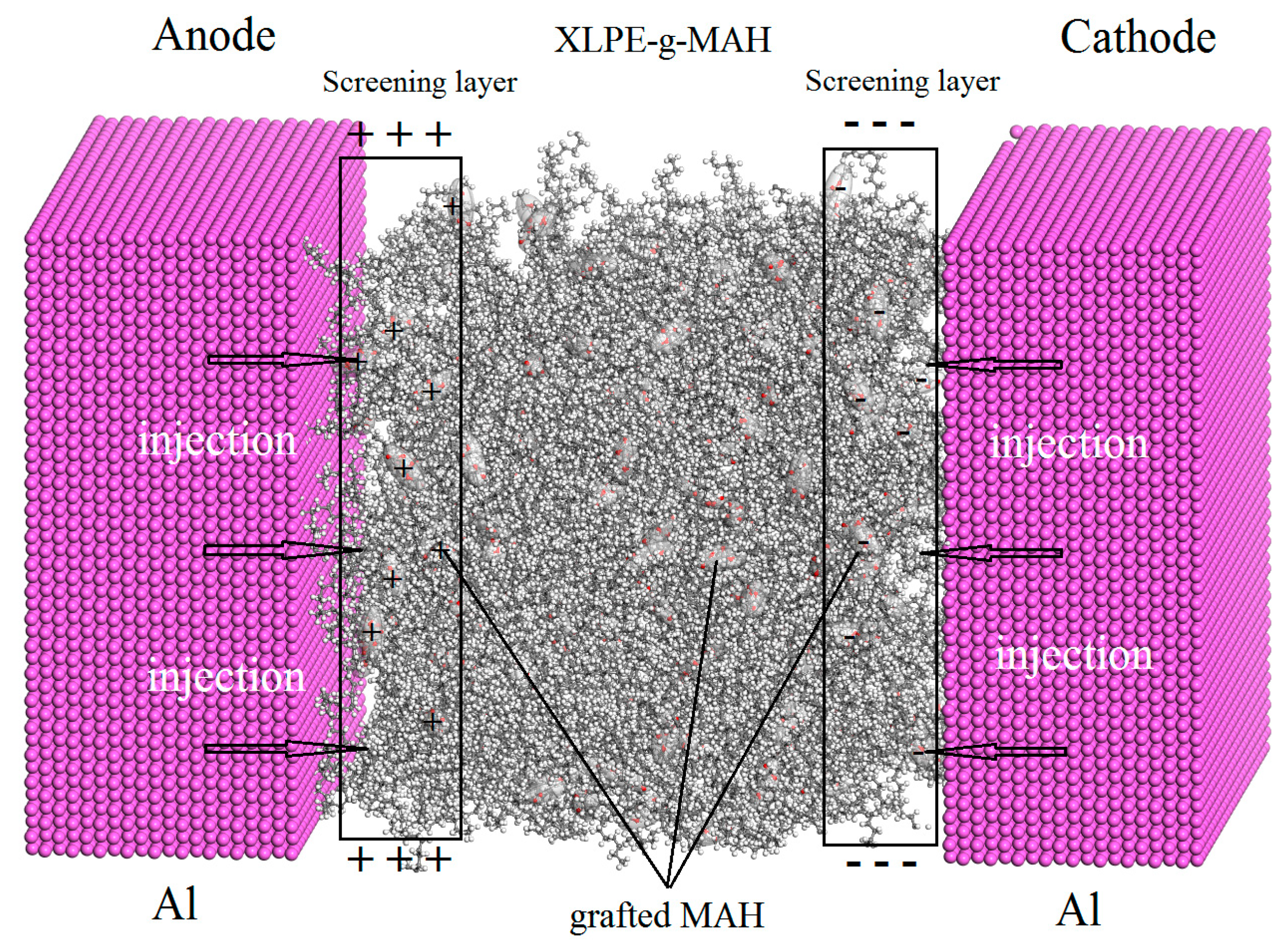
−3), respectively. The homogeneously distributed deep traps in high density being fixed on the grafted MAH will effectively capture the injected heterocharges and thus forms a charged Coulomb-potential screening layer near electrodes under DC electric field, which can block further charge injections and impede carrier transports. Hence, the space charge accumulations in XLPE-g-MAH is remarkably suppressed due to the deep traps introduced by grafting MAH onto polyethylene molecules, as schematically shown in
Figure 6. Furthermore, the graft-introduced traps being 0.3 eV deeper than intrinsic traps can retain highly efficient suppression mechanism of space charge accumulation at the elevated temperatures approaching to 150 °C, which is significantly higher than 55 °C for pure XLPE. These results suggest that XLPE-g-MAH can persist in high dielectric performances through the charge trapping mechanism at high temperatures rising to 150 °C.
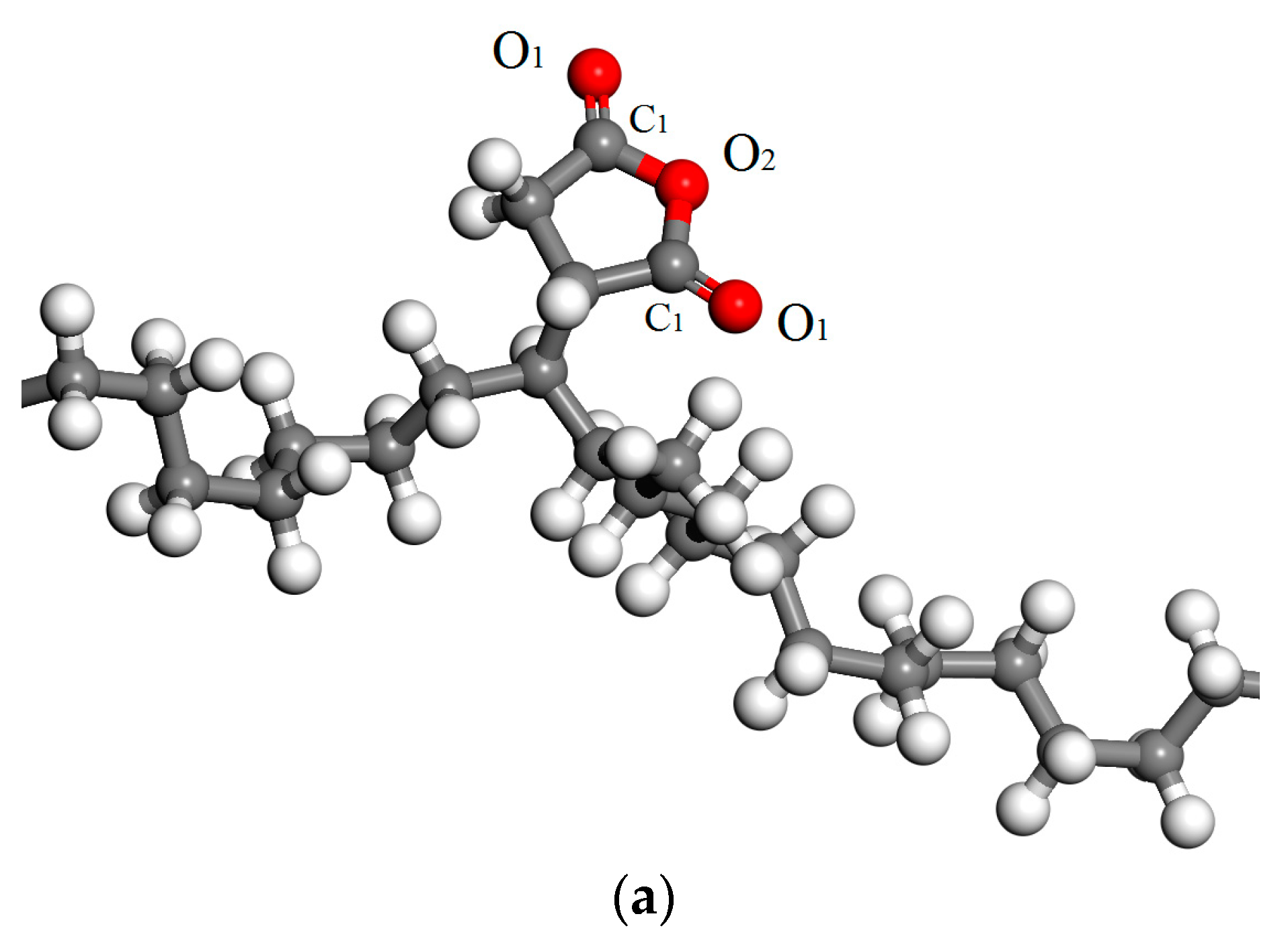
Energy levels of deep traps in XLPE-g-MAH materials have been derived from the TSC spectra to be about 1.25 eV. This result is consistent with the density of states (DOS) from the first-principles electronic structure calculations, as shown in
Figure 7 for the relaxed (geometrically optimized) model and the total/projected DOS of the polyethylene molecule grafted by MAH (PE-g-MAH). It could be verified by the DOS results of
Figure 7b that the background electronic states presented by polyethylene molecule in 30 polymeric degree form electronic bands in comparison to the local states confined in a few specific energy levels with a relatively minimal DOS values. The grafted MAH can introduce two unoccupied electronic bound states in the bandgap of polyethylene molecule, which will serve as the deep traps of free electrons in conduction band with the energy level of 1.3 and 1.8 eV reference to conduction band minimum (CBM). Very close to CBM, an unoccupied bound state of a little lower energy level is also introduced by the grafted MAH, which has merged into conduction band to become a new CBM, resulting in 0.4 eV reduction of bandgap.
The projected density of states (
Figure 7b) shows that the two trap states are mainly derived from the carbonyl-carbon atom (C
1) and a small fraction from the carbonyl-oxygen atom (O
1) of the grafted MAH, where the electron wave functions are distributed in local space around the carbonyl-bond (C=O). Two adjacent C=O bonds in the grafted MAH overlap and result in two unoccupied splitting molecular orbitals as the bound states, which can capture electrons in conduction band. The trap states of 1.8 eV are composed of 60% C
1 and 39% O
1 atomic orbitals, while the traps of 1.3 eV mainly come from C
1 atomic orbitals (>70%) with a minor part (<30%) from atomic orbitals of O
1 and O
2 (ester oxygen). The electronic structure results of theoretical calculations being consistent with experimental results of TSC further prove that the anhydride group of the grafted MAH can introduce electronic states of deep traps with energy levels among bandgap of polyethylene, which will efficiently scatter and capture electrons in conduction band. In supplement, the coupling of the anhydride groups on the grafted MAH splits the degenerate electronic states into a couple of electron deep traps, resulting in a deeper trap of 1.8 eV that cannot be verified by TSC experiments unless the testing temperature is raised to higher than ~300 °C which goes far beyond the operation temperature and exceeds the melting point of XLPE.
