
Fabricating Fibers of a Porous-Polystyrene Shell and Particle-Loaded Core

 , , , , , and
Abstract
1. Introduction
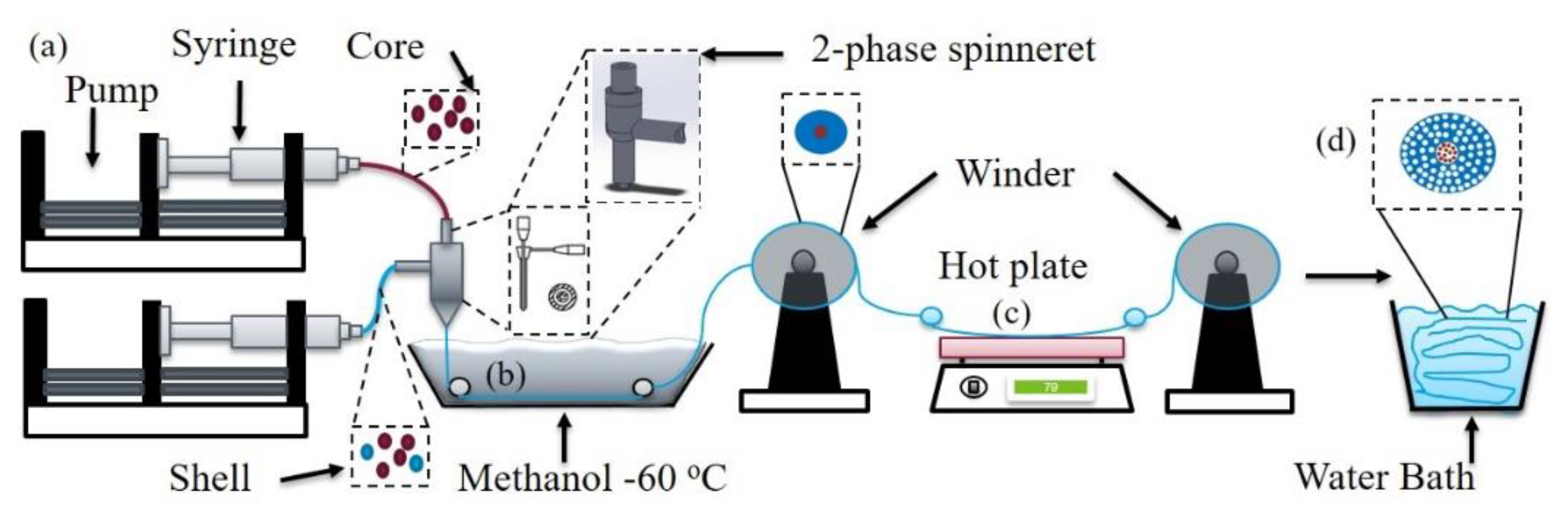
- (a)
- design of the spinneret (e.g., fiber morphology control),
- (b)
- choice of different materials (e.g., two or more phases of fibers, micro-fillers, and nanoparticles),
- (c)
- coagulation processes (e.g., bath temperatures, compositions, concentrations, and soaking time for fiber formations and producing even surface coatings),
- (d)
- filament windability (e.g., manufacturability and polymer morphology controls),
- (e)
- post-treatment steps (e.g., annealing, quenching, stress-applied healing, etc.).
2. Results and Discussions
2.1. Fabrication Design
- (a)
- allow the blended polymer mixtures to coagulate in the non-solvent to form fibers so that during the solvent/non-solvent exchanging process, the blended polymer solutions can transform from solution-state liquid to gel-state fiber precursors,
- (b)
- selectively dissolve the porogen in a solvent to create pores,
- (c)
- evenly distribute particles in the hollow cores,
- (d)
- simultaneously avoid losing particles from the constructed porous surfaces or hollow centers, (e.g., particle sizes should be smaller than the pore and be constrained by the core without flowing out).
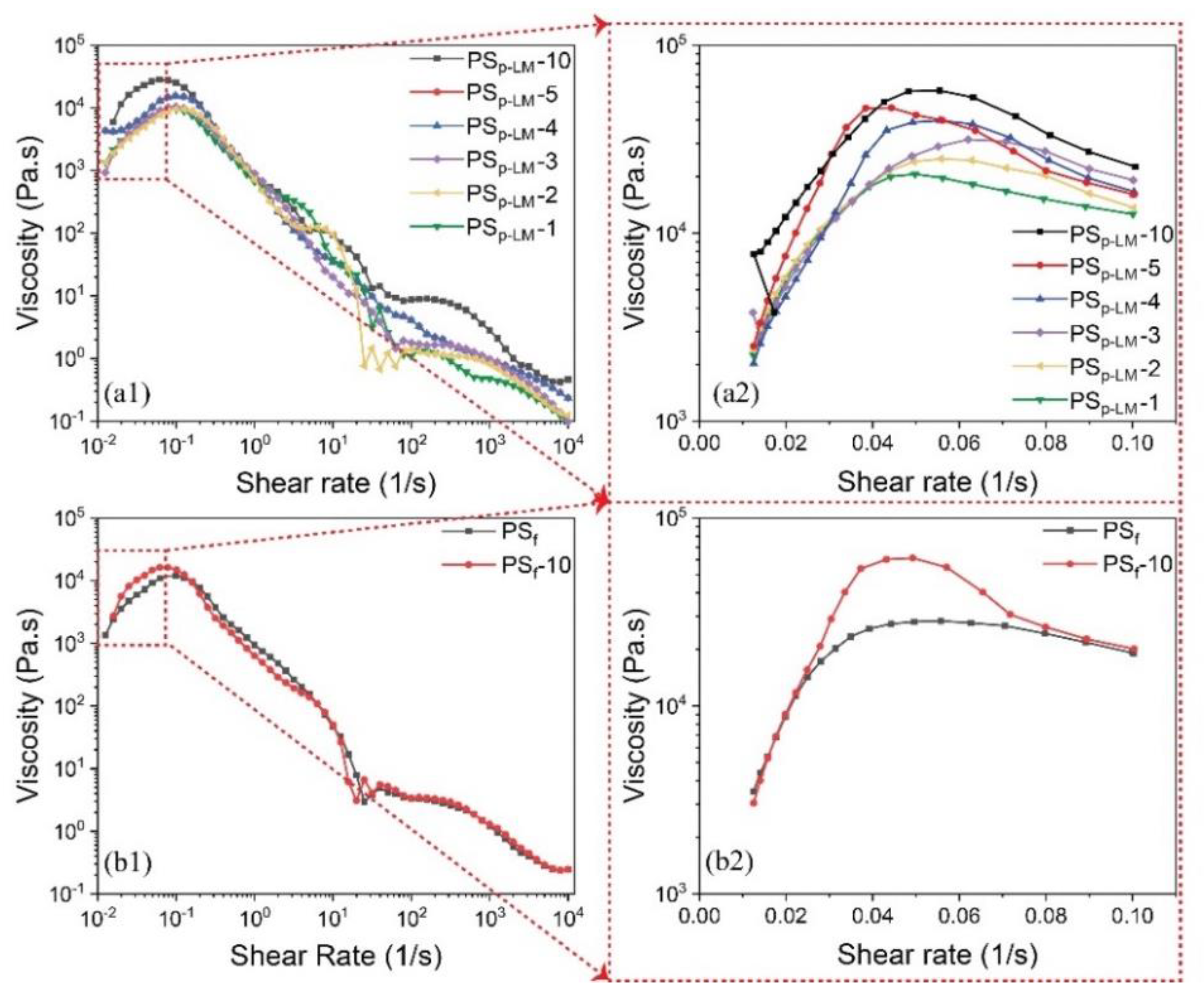
2.2. Influence of Rheology on Fiber Formations
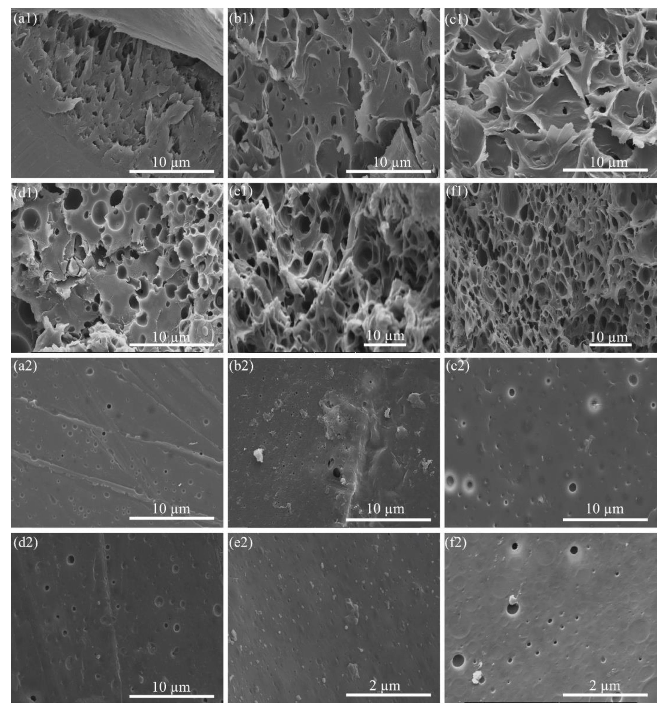
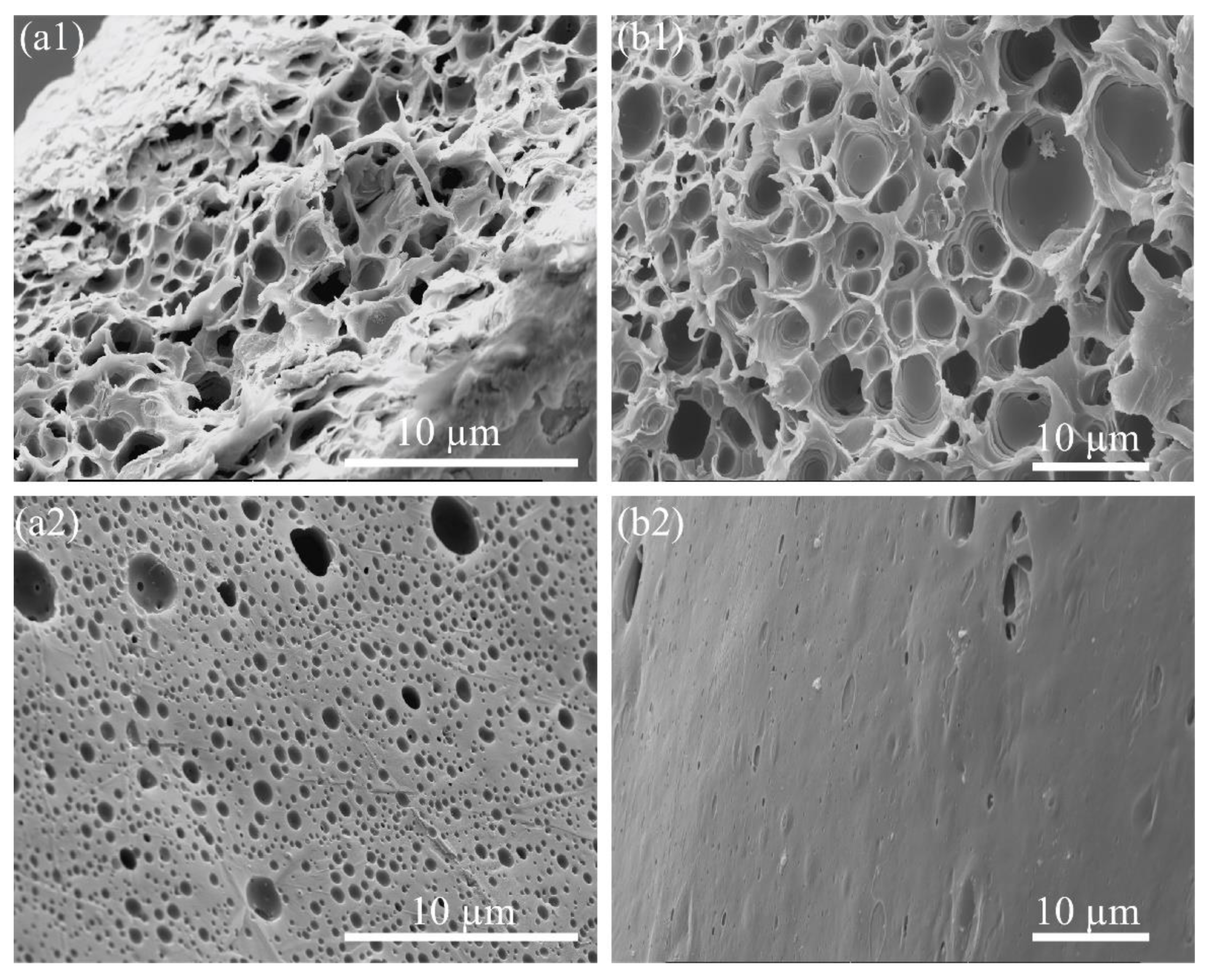
2.3. Influences of PEG Concentration on PS Porous Microstructures
2.4. Thermal Transitions of Fabricated Materials
2.5. Influence of the Solution on Particle Loading
3. Materials and Methods
3.1. Materials
3.2. Experimental Fabrications
3.3. Characterizations
4. Conclusions
Supplementary Materials
Author Contributions
Funding
Conflicts of Interest
References
- Deitzel, J.M.; Kleinmeyer, J.; Harris, D.; Beck Tan, N.C. The effect of processing variables on the morphology of electrospun. Polymer (Guildf.) 2001, 42, 261–272. [Google Scholar] [CrossRef]
- Koike, Y.; Ishigure, T.; Nihei, E. High-bandwidth graded-index polymer optical fiber. J. Light. Technol. 1995, 13, 1475–1489. [Google Scholar] [CrossRef]
- Ma, Y.; Bai, D.; Hu, X.; Ren, N.; Gao, W.; Chen, S.; Chen, H.; Lu, Y.; Li, J.; Bai, Y. Robust and antibacterial polymer/mechanically exfoliated graphene nanocomposite fibers for biomedical applications. Acs Appl. Mater. Interfaces 2018, 10, 3002–3010. [Google Scholar] [CrossRef]
- Bakis, C.E.; Bank, L.C.; Brown, V.L.; Cosenza, E.; Davalos, J.F.; Lesko, J.J.; Machida, A.; Rizkalla, S.H.; Triantafillou, T.C. Fiber-reinforced polymer composites for construction—state-of-the-art review. J. Compos. Constr. 2002, 6, 73–87. [Google Scholar] [CrossRef]
- Zeng, W.; Shu, L.; Li, Q.; Chen, S.; Wang, F.; Tao, X.M. Fiber-based wearable electronics: A review of materials, fabrication, devices, and applications. Adv. Mater. 2014, 26, 5310–5336. [Google Scholar] [CrossRef] [PubMed]
- Hufenus, R.; Reifler, F.A.; Maniura-Weber, K.; Spierings, A.; Zinn, M. Biodegradable bicomponent fibers from renewable sources: Melt-spinning of poly(lactic acid) and poly[(3-hydroxybutyrate)-co-(3-hydroxyvalerate)]. Macromol. Mater. Eng. 2012, 297, 75–84. [Google Scholar] [CrossRef]
- Perez, R.A.; Kim, H.-W. Core-shell designed scaffolds for drug delivery and tissue engineering. Acta Biomater. 2015, 21, 2–19. [Google Scholar] [CrossRef]
- Bae, H.S.; Haider, A.; Selim, K.M.K.; Kang, D.Y.; Kim, E.J.; Kang, I.K. Fabrication of highly porous PMMA electrospun fibers and their application in the removal of phenol and iodine. J. Polym. Res. 2013, 20. [Google Scholar] [CrossRef]
- Chen, Y.; Liu, B.; Chen, J.; Tian, L.; Huang, L.; Tu, M.; Tan, S. Structure design and photocatalytic properties of one-dimensional SnO2-TiO2 composites. Nanoscale Res. Lett. 2015, 10. [Google Scholar] [CrossRef]
- Singh, A.K.; Mandal, K. Engineering of high performance supercapacitor electrode based on Fe-Ni/Fe2O3-NiO core/shell hybrid nanostructures. J. Appl. Phys. 2015, 117, 105101. [Google Scholar] [CrossRef]
- Hwang, T.H.; Lee, Y.M.; Kong, B.S.; Seo, J.S.; Choi, J.W. Electrospun core-shell fibers for robust silicon nanoparticle-based lithium ion battery anodes. Nano Lett. 2012, 12, 802–807. [Google Scholar] [CrossRef] [PubMed]
- Peng, F.; Jiang, H.; Woods, A.; Joo, P.; Amis, E.J.; Zacharia, N.S.; Vogt, B.D. 3D printing with core–shell filaments containing high or low density polyethylene shells. Acs Appl. Polym. Mater. 2019, 1, 275–285. [Google Scholar] [CrossRef]
- Hufenus, R.; Fortunato, G.; Gottardo, L.; Reifler, F.A. Multicomponent synthetic fibers for innovative textile applications. In Proceedings of the International Symposium on Fiber Science and Technology, Tokyo, Japan, 28 September 2014. [Google Scholar]
- Dasdemir, M.; Maze, B.; Anantharamaiah, N.; Pourdeyhimi, B. Influence of polymer type, composition, and interface on the structural and mechanical properties of core/sheath type bicomponent nonwoven fibers. J. Mater. Sci. 2012, 47, 5955–5969. [Google Scholar] [CrossRef]
- Deng, H.; Skipa, T.; Bilotti, E.; Zhang, R.; Lellinger, D.; Mezzo, L.; Fu, Q.; Alig, I.; Peijs, T. Preparation of high-performance conductive polymer fibers through morphological control of networks formed by nanofillers. Adv. Funct. Mater. 2010, 20, 1424–1432. [Google Scholar] [CrossRef]
- Shi, X.Q.; Ito, H.; Kikutani, T. Structure development and properties of high-speed melt spun poly(butylene terephthalate)/poly(butylene adipate-co-terephthalate) bicomponent fibers. Polymer (Guildf.) 2006, 47, 611–616. [Google Scholar] [CrossRef]
- Reifler, F.A.; Hufenus, R.; Krehel, M.; Zgraggen, E.; Rossi, R.M.; Scherer, L.J. Polymer optical fibers for textile applications—bicomponent melt spinning from cyclic olefin polymer and structural characteristics revealed by wide angle X-ray diffraction. Polymer (Guildf.) 2014, 55, 5695–5707. [Google Scholar] [CrossRef]
- Wu, X.F.; Rahman, A.; Zhou, Z.; Pelot, D.D.; Sinha-Ray, S.; Chen, B.; Payne, S.; Yarin, A.L. Electrospinning core-shell nanofibers for interfacial toughening and self-healing of carbon-fiber/epoxy composites. J. Appl. Polym. Sci. 2013, 129, 1383–1393. [Google Scholar] [CrossRef]
- Naeimirad, M.; Zadhoush, A.; Kotek, R.; Esmaeely Neisiany, R.; Nouri Khorasani, S.; Ramakrishna, S. Recent advances in core/shell bicomponent fibers and nanofibers: A review. J. Appl. Polym. Sci. 2018, 135, 28–30. [Google Scholar] [CrossRef]
- Li, J.; Ge, S.; Wang, J.; Du, H.; Song, K.; Fei, Z.; Shao, Q.; Guo, Z. Water-based rust converter and its polymer composites for surface anticorrosion. Colloids Surf. A Phys. Eng. Asp. 2018, 537, 334–342. [Google Scholar] [CrossRef]
- Wolosiuk, A.; Armagan, O.; Braun, P.V. Double direct templating of periodically nanostructured ZnS hollow microspheres. J. Am. Chem. Soc. 2005, 127, 16356–16357. [Google Scholar] [CrossRef]
- Jenekhe, S.A.; Chen, X.L. Self-assembly of ordered microporous materials from rod-coil block copolymers. Science 1999, 283, 372–375. [Google Scholar] [CrossRef] [PubMed]
- Ma, T.Y.; Liu, L.; Yuan, Z.Y. Direct synthesis of ordered mesoporous carbons. Chem. Soc. Rev. 2013, 42, 3977–4003. [Google Scholar] [CrossRef] [PubMed]
- Cameron, N.R. High internal phase emulsion templating as a route to well-defined porous polymers. Polymer (Guildf.) 2005, 46, 1439–1449. [Google Scholar] [CrossRef]
- Sukitpaneenit, P.; Chung, T.S. High performance thin-film composite forward osmosis hollow fiber membranes with macrovoid-free and highly porous structure for sustainable water production. Env. Sci. Technol. 2012, 46, 7358–7365. [Google Scholar] [CrossRef] [PubMed]
- Pai, C.L.; Boyce, M.C.; Rutledge, G.C. Morphology of porous and wrinkled fibers of polystyrene electrospun from dimethylformamide. Macromolecules 2009, 42, 2102–2114. [Google Scholar] [CrossRef]
- Khare, V.P.; Greenberg, A.R.; Krantz, W.B. Vapor-induced phase separation—effect of the humid air exposure step on membrane morphology Part I Insights from mathematical modeling. J. Memb. Sci. 2005, 258, 140–156. [Google Scholar] [CrossRef]
- Gupta, A.; Saquing, C.D.; Afshari, M.; Tonelli, A.E.; Khan, S.A.; Kotek, R. Porous nylon-6 fibers via a novel salt-induced electrospinning method. Macromolecules 2009, 42, 709–715. [Google Scholar] [CrossRef]
- Peng, M.; Li, D.; Shen, L.; Chen, Y.; Zheng, Q.; Wang, H. Nanoporous structured submicrometer carbon fibers prepared via solution electrospinning of polymer blends. Langmuir 2006, 22, 9368–9374. [Google Scholar] [CrossRef]
- Lackner, K.S. Capture of carbon dioxide from ambient air. Eur. Phys. J. Spec. Top. 2009, 176, 93–106. [Google Scholar] [CrossRef]
- Lin, J.; Ding, B.; Jianyong, Y.; Hsieh, Y. Direct fabrication of highly nanoporous polystyrene fibers via electrospinning. Acs Appl. Mater. Interfaces 2010, 2, 521–528. [Google Scholar] [CrossRef]
- Gulfam, M.; Lee, J.M.; Kim, J.-E.; Lim, D.W.; Lee, E.K.; Chung, B.G. Highly porous coreàshell polymeric fiber network. Langmuir 2011, 27, 10993–10999. [Google Scholar] [CrossRef] [PubMed]
- Khajavi, R.; Abbasipour, M. Electrospinning as a versatile method for fabricating coreshell, hollow and porous nanofibers. Sci. Iran. 2012, 19, 2029–2034. [Google Scholar] [CrossRef]
- Zhang, J.-F.; Yang, D.-Z.; Xu, F.; Zhang, Z.-P.; Yin, R.-X.; Nie, J. Electrospun core-shell structure nanofibers from homogeneous solution of poly(ethylene oxide)/chitosan. Macromolecules 2009, 42, 5278–5284. [Google Scholar] [CrossRef]
- Bhardwaj, N.; Kundu, S.C. Electrospinning: A fascinating fiber fabrication technique. Biotechnol. Adv. 2010, 28, 325–347. [Google Scholar] [CrossRef] [PubMed]
- Vasita, R.; Katti, D.S. Nanofibers and their applications in tissue engineering. Int. J. Nanomed. 2006, 1, 15–30. [Google Scholar] [CrossRef] [PubMed]
- Ramakrishna, S.; Fujihara, K.; Teo, W.-E.; Lim, T.-C.; Ma, Z. An introduction to electrospinning and nanofibers; World Scientific: Singapore, 2005; ISBN 978-981-256-415-3. [Google Scholar]
- Meng, J.; Zhang, Y.; Song, K.; Minus, M.L. Forming crystalline polymer-nano interphase structures for high-modulus and high-tensile/strength composite fibers. Macromol. Mater. Eng. 2014, 299, 144–153. [Google Scholar] [CrossRef]
- Song, K.; Minus, M.L.; Avenue, H. Inducing polymer interphase formation in the composite at low nano-carbon loading. Nsti-Nanotech 2014, 1, 324–327. [Google Scholar]
- Song, K.; Zhang, Y.; Minus, M.L. Polymer interphase self-reinforcement and strengthening mechanisms in low-loaded nanocomposite fibers. Macromol. Chem. Phys. 2015, 216, 1313–1320. [Google Scholar] [CrossRef]
- Song, K.; Zhang, Y.; Meng, J.; Green, E.C.; Tajaddod, N.; Li, H.; Minus, M.L. Structural polymer-based carbon nanotube composite fibers: Understanding the processing-structure-performance relationship. Materials 2013, 6, 2543–2577. [Google Scholar] [CrossRef]
- Xu, W.; Jambhulkar, S.; Verma, R.; Franklin, R.; Ravichandran, D.; Song, K. In situ alignment of graphene nanoplatelets in poly(vinyl alcohol) nanocomposite fibers with controlled stepwise interfacial exfoliation. Nanoscale Adv. 2019, 1, 2510–2517. [Google Scholar] [CrossRef]
- Hunt, E.J.; Zhang, C.; Anzalone, N.; Pearce, J.M. Polymer recycling codes for distributed manufacturing with 3D printers. Resour. Conserv. Recycl. 2015, 97, 24–30. [Google Scholar] [CrossRef]
- El-Fadel, M.; Findikakis, A.N.; Leckie, J.O. Environmental impacts of solid waste landfilling. J. Env. Manag. 1997, 50, 1–25. [Google Scholar] [CrossRef]
- Zhang, T.; Fiedler, H.; Yu, G.; Ochoa, G.S.; Carroll, W.F.; Gullett, B.K.; Marklund, S.; Touati, A. Emissions of unintentional persistent organic pollutants from open burning of municipal solid waste from developing countries. Chemosphere 2011, 84, 994–1001. [Google Scholar] [CrossRef] [PubMed]
- Al-Salem, S.M.; Lettieri, P.; Baeyens, J. Recycling and recovery routes of plastic solid waste (PSW): A review. Waste Manag. 2009, 29, 2625–2643. [Google Scholar] [CrossRef] [PubMed]
- García, M.T.; Gracia, I.; Duque, G.; de Lucas, A.; Rodríguez, J.F. Study of the solubility and stability of polystyrene wastes in a dissolution recycling process. Waste Manag. 2009, 29, 1814–1818. [Google Scholar] [CrossRef] [PubMed]
- Kadajji, V.G.; Betageri, G.V. Water soluble polymers for pharmaceutical applications. Polymers 2011, 3, 1972–2009. [Google Scholar] [CrossRef]
- Nezarati, R.M.; Eifert, M.B.; Cosgriff-hernandez, E. Effects of Humidity and Solution Viscosity on Electrospun Fiber Morphology. Tissue. Engg. Part. CMary. Ann. LiebertInc. 2013, 19, 810–819. [Google Scholar] [CrossRef]
- Wongchitphimon, S.; Wang, R.; Jiraratananon, R.; Shi, L.; Heng, C. Effect of polyethylene glycol (PEG) as an additive on the fabrication of polyvinylidene fluoride-co-hexafluropropylene (PVDF-HFP) asymmetric microporous hollow fiber membranes. J. Memb. Sci. 2011, 369, 329–338. [Google Scholar] [CrossRef]
- Flory, P.J. Principles of Polymer Chemistry; Cornell University Press: Ithaca, NY, USA, 1953; Volume 245, ISBN 0801401348. [Google Scholar]
- Guo, S.Z.; Yang, X.; Heuzey, M.C.; Therriault, D. 3D printing of a multifunctional nanocomposite helical liquid sensor. Nanoscale 2015, 7, 6451–6456. [Google Scholar] [CrossRef]
- Spencer, R.S.; Williams, J.L. Concentrated Solution Viscosity of Polystyrene. Dow Chem. Co. 1946, 2, 117–129. [Google Scholar] [CrossRef]
- Sharpe, I.D.; Ismail, A.F.; Shilton, S.J. A study of extrusion shear and forced convection residence time in the spinning of polysulfone hollow fiber membranes for gas separation. Sep. Purif. Technol. 1999, 17, 101–109. [Google Scholar] [CrossRef]
- Dintzis, E.B.B.F.R. Shear thickening and flow induced structures in foods and biopolymers systems. Rheol. Ser. 1999, 8, 63–86. [Google Scholar]
- Kayaci, F.; Ozgit-Akgun, C.; Donmez, I.; Biyikli, N.; Uyar, T. Polymer-inorganic core-shell nanofibers by electrospinning and atomic layer deposition: Flexible nylon-ZnO core-shell nanofiber mats and their photocatalytic activity. Acs Appl. Mater. Interfaces 2012, 4, 6185–6194. [Google Scholar] [CrossRef] [PubMed]
- Ma, W.; Guo, Z.; Zhao, J.; Yu, Q.; Wang, F.; Han, J.; Pan, H.; Yao, J.; Zhang, Q.; Samal, S.K.; et al. Polyimide/cellulose acetate core/shell electrospun fibrous membranes for oil-water separation. Sep. Purif. Technol. 2017, 177, 71–85. [Google Scholar] [CrossRef]
- Wang, W.; Zeng, Q.; Li, M.; Zheng, W.; Christianson, D.; Economy, J. Adsorptive removal of carbon dioxide using polyethyleneimine loaded glass fiber in a fixed bed. Colloids Surf. A Phys. Eng. Asp. 2015, 481, 117–124. [Google Scholar] [CrossRef]
Sample Availability: Not available. |


| Samples | DSC | TGA | |||||
|---|---|---|---|---|---|---|---|
| Tg (°C) | ΔH (J/g) | Tm (°C) | Main Peak Temperature of the Curve Derivative (°C) | Ti1 (°C) | Ti2 (°C) | Tf (°C) | |
| As-obtained raw materials | |||||||
| PSp-LM | 102.07 | - | - | 410.11 | - | 287.29 | 430.61 |
| PEG Flakes | - | 179.49 | 63.94 | 366.35 | - | 218.60 | 384.56 |
| Fabricated and post-processed fibers | |||||||
| PSp-LM fiber | 101.62 | - | - | 337.06 | 132.49 | 287.86 | 370.24 |
| PSp-LM-10 fiber | 102.06 | 10.32 | 61.48 | 375.17 | 145.46 | 295.42 | 404.11 |
| Porous PSp-LM-10 fiber | 102.21 | 7.13 | 61.27 | 360.05 | 142.43 | 293.29 | 397.41 |
| Sample | PEG/PS wt. % in Shells | PEG/Water wt. % in Core | Particle/PEG wt. % in Core | Preparations |
|---|---|---|---|---|
| PSp-LM-1 | 1 | 0 | 0 | (i) A 35 wt. % PSp concentration in xylene was prepared as a solution; (ii) 1, 2, 3, 4, 5, and 10 wt. % PEG as a ratio to PSp/xylene solution was added to the solution as spinning batches; (iii) The spinning solutions were gel-spun as fibers and heat-treated; (iv) The solid fibers were soaked in the water to get dissolved PEG to form pores. The porous fibers were dried before further characterizations. |
| PSp-LM-2 | 2 | |||
| PSp-LM-3 | 3 | |||
| PSp-LM-4 | 4 | |||
| PSp-LM-5 | 5 | |||
| PSp-LM-10 | 10 | |||
| PSp-LM-10/PEG core | 10 | 80 | 0 | (v) Shell solutions as mentioned above; core solutions were 80 wt. % PEG/water. |
| PSp-LM-10/PSs | 10 | 80 | 30 | (vi) Shell solutions as mentioned above; 30 wt. % PSs/PEG was prepared for the core solutions. |
| PSp-HM-10 | 10 | 0 | 0 | (vii) A 35 wt. % PSp concentration in xylene with 10 wt. % PEG was prepared as a solution and followed step iii and iv. |
| PSf-10 | 10 | 0 | 0 | (viii) 35 wt. % of PSf concentration in xylene with 10 wt. % PEG was prepared as a solution and followed step iii and iv. |
© 2019 by the authors. Licensee MDPI, Basel, Switzerland. This article is an open access article distributed under the terms and conditions of the Creative Commons Attribution (CC BY) license (http://creativecommons.org/licenses/by/4.0/).
Share and Cite
Ravichandran, D.; Xu, W.; Franklin, R.; Kanth, N.; Jambhulkar, S.; Shukla, S.; Song, K. Fabricating Fibers of a Porous-Polystyrene Shell and Particle-Loaded Core. Molecules 2019, 24, 4142. https://doi.org/10.3390/molecules24224142
Ravichandran D, Xu W, Franklin R, Kanth N, Jambhulkar S, Shukla S, Song K. Fabricating Fibers of a Porous-Polystyrene Shell and Particle-Loaded Core. Molecules. 2019; 24(22):4142. https://doi.org/10.3390/molecules24224142
Chicago/Turabian StyleRavichandran, Dharneedar, Weiheng Xu, Rahul Franklin, Namrata Kanth, Sayli Jambhulkar, Sumedh Shukla, and Kenan Song. 2019. "Fabricating Fibers of a Porous-Polystyrene Shell and Particle-Loaded Core" Molecules 24, no. 22: 4142. https://doi.org/10.3390/molecules24224142
APA StyleRavichandran, D., Xu, W., Franklin, R., Kanth, N., Jambhulkar, S., Shukla, S., & Song, K. (2019). Fabricating Fibers of a Porous-Polystyrene Shell and Particle-Loaded Core. Molecules, 24(22), 4142. https://doi.org/10.3390/molecules24224142