Modelling of Mechanical Behavior of Biopolymer Alginate Aerogels Using the Bonded-Particle Model


Abstract

1. Introduction
2. Results
2.1. Experimental Characterisation
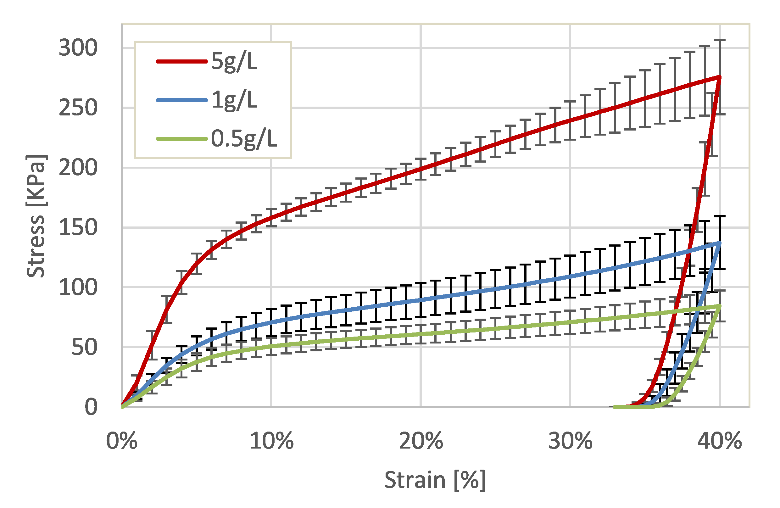
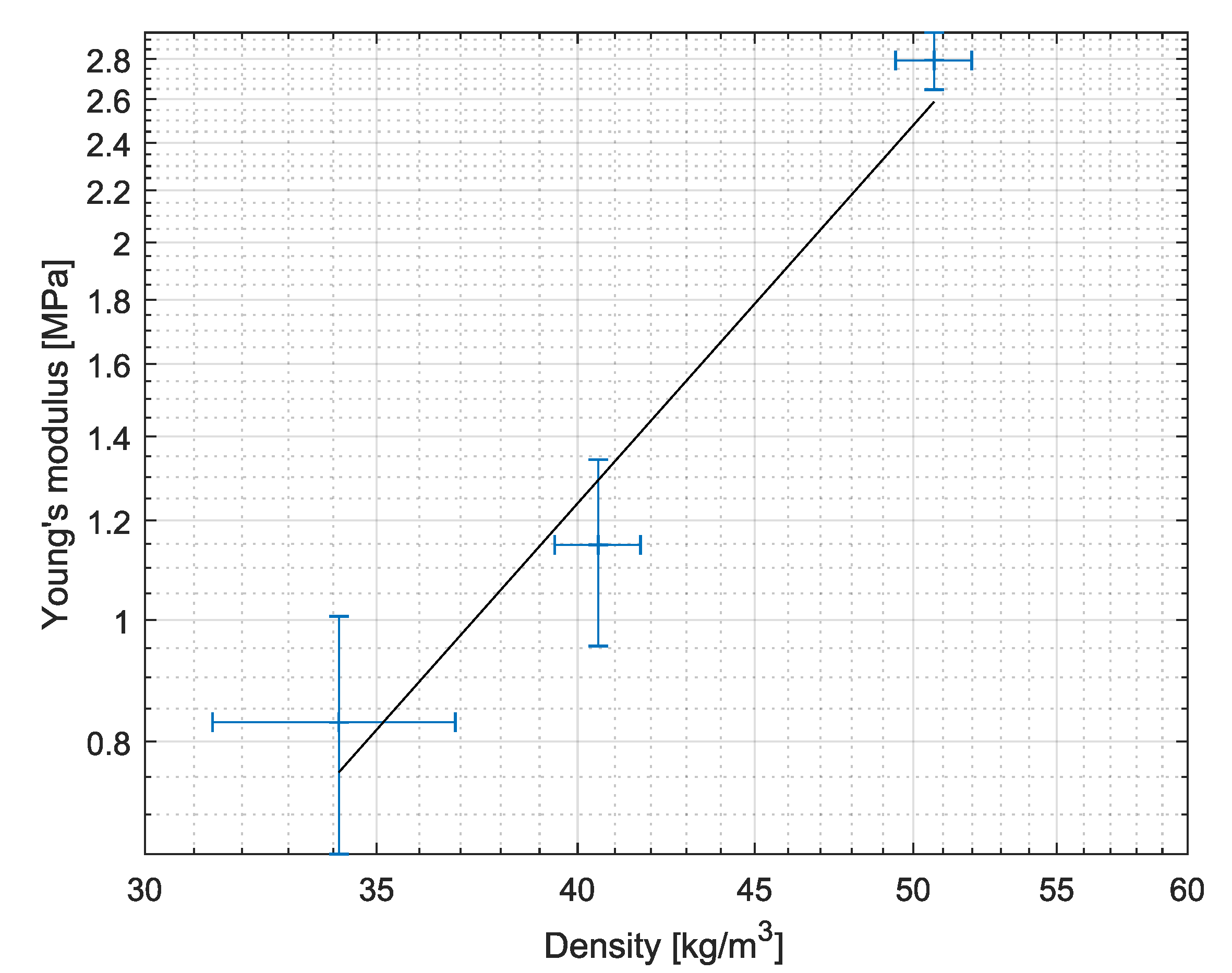
2.1.1. Mechanical Behavior
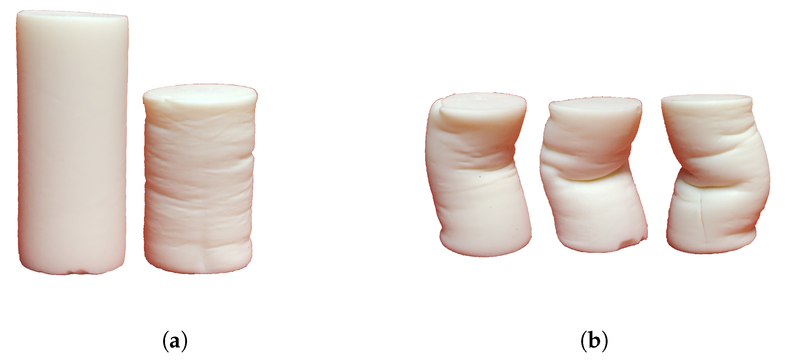
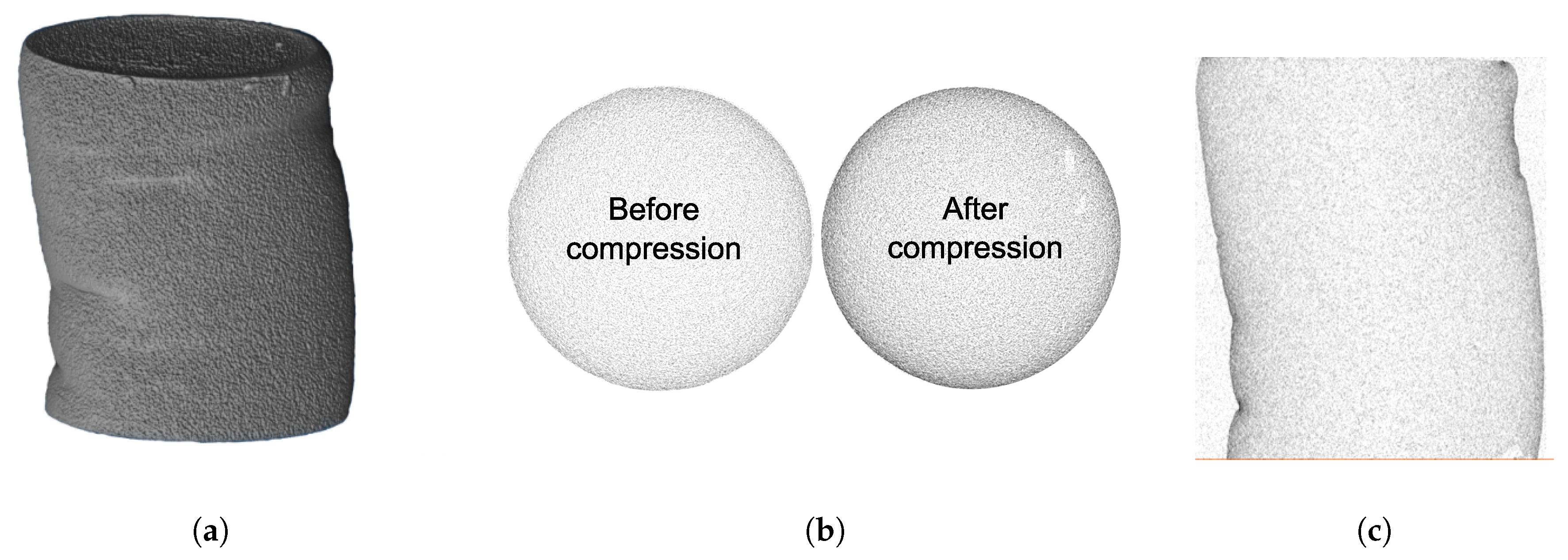
2.1.2. Deformation and Densification
2.2. Simulation Results
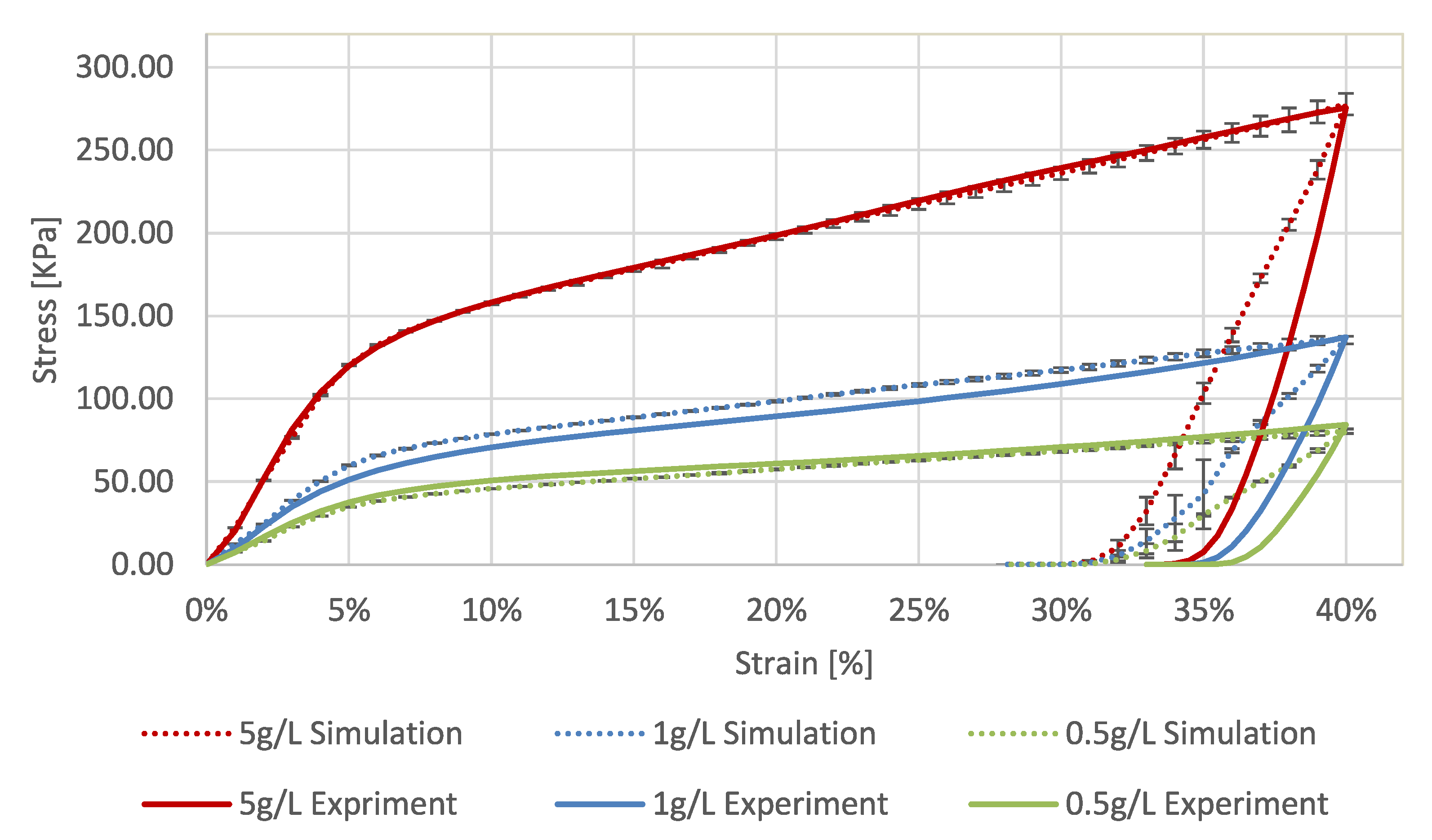
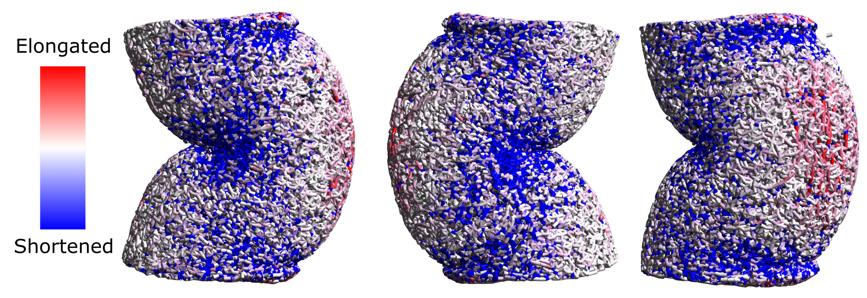
2.2.1. Uni-Axial Compression
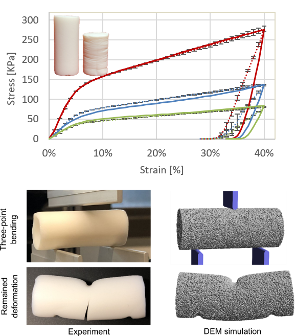
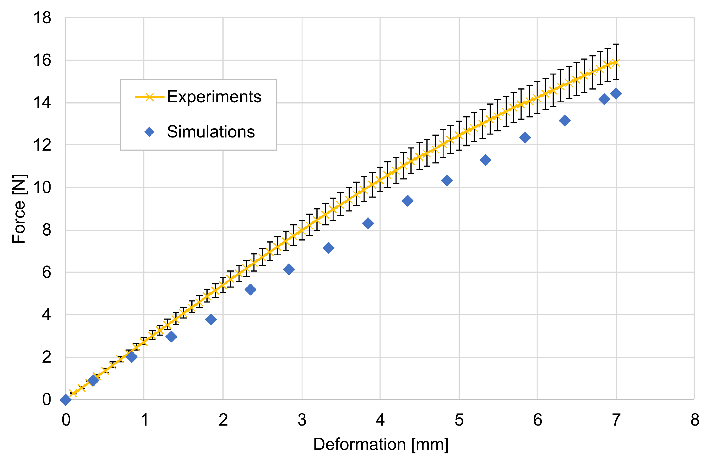
2.2.2. Three-Point Bending
3. Discussion
4. Materials and Methods
4.1. Materials
4.2. Modelling Approach
4.2.1. Bonded-Particle Model
- structural model: spatial material distribution, positions and radii of primary particles, connection between primary particles, bonds radii, etc.;
- functional model: functional dependencies to describe forces and moments acting in the bonds and between primary particles;
- model parameters: model parameters to describe plasticity, softening, and so forth.
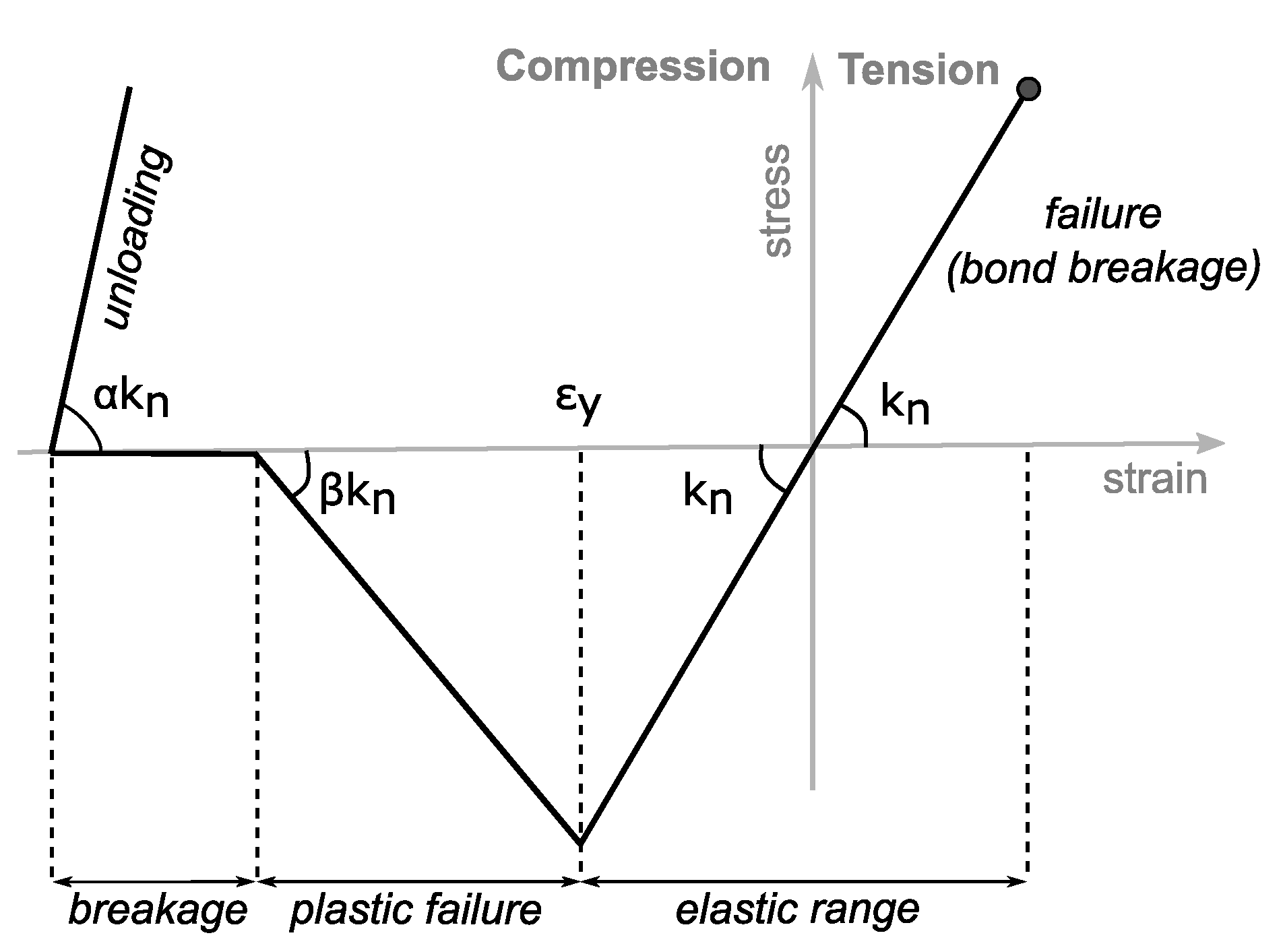
4.2.2. Elasto-Plastic Bond Model
4.2.3. Adjustment of Model Parameters
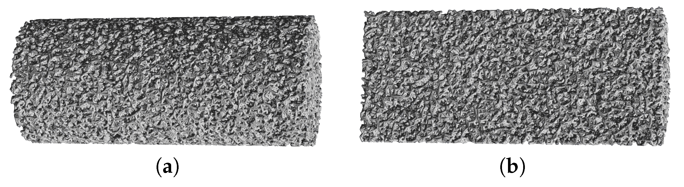
4.2.4. Model Setup
Author Contributions
Funding
Acknowledgments
Conflicts of Interest
Abbreviations
| BPM | Bonded Particle Model |
| DEM | Discrete Element Method |
| CT | Micro Computed Tomography |
References
- Plackett, D. Biopolymers—New Materials for Sustainable Films and Coatings. In Biopolymers; Plackett, D.V., Ed.; Wiley: Oxford, UK, 2011. [Google Scholar] [CrossRef]
- Rudaz, C.; Courson, R.; Bonnet, L.; Calas-Etienne, S.; Sallée, H.; Budtova, T. Aeropectin: Fully biomass-based mechanically strong and thermal superinsulating aerogel. Biomacromolecules 2014, 15, 2188–2195. [Google Scholar] [CrossRef] [PubMed]
- Gurikov, P.; Raman, S.P.; Weinrich, D.; Fricke, M.; Smirnova, I. A novel approach to alginate aerogels: Carbon dioxide induced gelation. RSC Adv. 2015, 5, 7812–7818. [Google Scholar] [CrossRef]
- Kobayashi, Y.; Saito, T.; Isogai, A. Aerogels with 3D ordered nanofiber skeletons of liquid-crystalline nanocellulose derivatives as tough and transparent insulators. Angew. Chem. (Int. Ed. Engl.) 2014, 53, 10394–10397. [Google Scholar] [CrossRef] [PubMed]
- Takeshita, S.; Yoda, S. Chitosan Aerogels: Transparent, Flexible Thermal Insulators. Chem. Mater. 2015, 27, 7569–7572. [Google Scholar] [CrossRef]
- Demilecamps, A.; Beauger, C.; Hildenbrand, C.; Rigacci, A.; Budtova, T. Cellulose-silica aerogels. Carbohydr. Polym. 2015, 122, 293–300. [Google Scholar] [CrossRef] [PubMed]
- Cheng, Y.; Lu, L.; Zhang, W.; Shi, J.; Cao, Y. Reinforced low density alginate-based aerogels: Preparation, hydrophobic modification and characterization. Carbohydr. Polym. 2012, 88, 1093–1099. [Google Scholar] [CrossRef]
- Goslinska, M.; Selmer, I.; Kleemann, C.; Kulozik, U.; Smirnova, I.; Heinrich, S. Novel technique for measurement of coating layer thickness of fine and porous particles using focused ion beam. Particuology 2019, 42, 190–198. [Google Scholar] [CrossRef]
- Rivas Murillo, J.S.; Bachlechner, M.E.; Campo, F.A.; Barbero, E.J. Structure and mechanical properties of silica aerogels and xerogels modeled by molecular dynamics simulation. J. Non-Cryst. Solids 2010, 356, 1325–1331. [Google Scholar] [CrossRef]
- Lei, J.; Liu, Z.; Yeo, J.; Ng, T.Y. Determination of the Young’s modulus of silica aerogels—An analytical—Numerical approach. Soft Matter 2013, 9, 11367. [Google Scholar] [CrossRef]
- Patil, S.P.; Rege, A.; Itskov, M.; Markert, B. Mechanics of Nanostructured Porous Silica Aerogel Resulting from Molecular Dynamics Simulations. J. Phys. Chem. 2017, 121, 5660–5668. [Google Scholar] [CrossRef]
- Gelb, L.D. Simulating silica aerogels with a coarse-grained flexible model and langevin dynamics. J. Phys. Chem. 2007, 111, 15792–15802. [Google Scholar] [CrossRef]
- Ferreiro-Rangel, C.A.; Gelb, L.D. Computational Study of Uniaxial Deformations in Silica Aerogel Using a Coarse-Grained Model. J. Phys. Chem. 2015, 119, 8640–8650. [Google Scholar] [CrossRef] [PubMed]
- Ma, Y.; Huang, H. A displacement-softening contact model for discrete element modeling of quasi-brittle materials. Int. J. Rock Mech. Min. Sci. 2018, 104, 9–19. [Google Scholar] [CrossRef]
- Zhao, S.; Malfait, W.J.; Guerrero-Alburquerque, N.; Koebel, M.M.; Nyström, G. Biopolymer Aerogels and Foams: Chemistry, Properties, and Applications. Angew. Chem.-Int. Ed. 2018, 57, 7580–7608. [Google Scholar] [CrossRef] [PubMed]
- Rege, A.; Schestakow, M.; Karadagli, I.; Ratke, L.; Itskov, M. Micro-mechanical modelling of cellulose aerogels from molten salt hydrates. Soft Matter 2016, 12, 7079–7088. [Google Scholar] [CrossRef] [PubMed]
- Rege, A.; Preibisch, I.; Schestakow, M.; Ganesan, K.; Gurikov, P.; Milow, B.; Smirnova, I.; Itskov, M. Correlating Synthesis Parameters to Morphological Entities: Predictive Modeling of Biopolymer Aerogels. Materials 2018, 11, 1670. [Google Scholar] [CrossRef] [PubMed]
- Rege, A.; Hillgärtner, M.; Itskov, M. Mechanics of biopolymer aerogels based on microstructures generated from 2-d Voronoi tessellations. J. Supercrit. Fluids 2019, 151, 24–29. [Google Scholar] [CrossRef]
- Potyondy, D.O.; Cundall, P.A. A bonded-particle model for rock. Int. J. Rock Mech. Min. Sci. 2004, 41, 1329–1364. [Google Scholar] [CrossRef]
- Potyondy, D.O. The bonded-particle model as a tool for rock mechanics research and application: current trends and future directions. Geosyst. Eng. 2015, 18, 1–28. [Google Scholar] [CrossRef]
- Dosta, M.; Dale, S.; Antonyuk, S.; Wassgren, C.; Heinrich, S.; Litster, J.D. Numerical and experimental analysis of influence of granule microstructure on its compression breakage. Powder Technol. 2016, 299, 87–97. [Google Scholar] [CrossRef]
- Nitka, M.; Tejchman, J. Modelling of concrete behaviour in uniaxial compression and tension with DEM. Granul. Matter 2015, 17, 145–164. [Google Scholar] [CrossRef]
- Wu, H.; Zhao, J.; Guo, N. Multiscale Insights Into Borehole Instabilities in High-Porosity Sandstones. J. Geophys. Res. Solid Earth 2018, 123, 3450–3473. [Google Scholar] [CrossRef]
- Wu, H.; Guo, N.; Zhao, J. Multiscale modeling and analysis of compaction bands in high-porosity sandstones. Acta Geotech. 2018, 13, 575–599. [Google Scholar] [CrossRef]
- Spettl, A.; Bachstein, S.; Dosta, M.; Goslinska, M.; Heinrich, S.; Schmidt, V. Bonded-particle extraction and stochastic modeling of internal agglomerate structures. Adv. Powder Technol. 2016, 27, 1761–1774. [Google Scholar] [CrossRef]
- Nguyen, N.H.; Bui, H.H.; Nguyen, G.D.; Kodikara, J. A cohesive damage-plasticity model for DEM and its application for numerical investigation of soft rock fracture properties. Int. J. Plast. 2017, 98, 175–196. [Google Scholar] [CrossRef]
- Kim, H.; Buttlar, W.G. Discrete fracture modeling of asphalt concrete. Int. J. Solids Struct. 2009, 46, 2593–2604. [Google Scholar] [CrossRef]
- Tran, V.T.; Donze, F.V.; Marin, P. Discrete element model of concrete under high confining pressure. In Fracture Mechanics of Concrete and Concrete Structures; Oh, B.H., Choi, O.C., Chung, L., Eds.; Ia-FraMCos and Korea Concrete Institute: Seoul, Korea, 2010. [Google Scholar]
- Ma, H.; Zheng, X.; Luo, X.; Yi, Y.; Yang, F. Simulation and analysis of mechanical properties of silica aerogels: From rationalization to prediction. Materials 2018, 11, 214. [Google Scholar] [CrossRef]
- Karadagli, I.; Schulz, B.; Schestakow, M.; Milow, B.; Gries, T.; Ratke, L. Production of porous cellulose aerogel fibers by an extrusion process. J. Supercrit. Fluids 2015, 106, 105–114. [Google Scholar] [CrossRef]
- Agulhon, P.; Robitzer, M.; Habas, J.P.; Quignard, F. Influence of both cation and alginate nature on the rheological behavior of transition metal alginate gels. Carbohydr. Polym. 2014, 112, 525–531. [Google Scholar] [CrossRef]
- Spettl, A.; Dosta, M.; Antonyuk, S.; Heinrich, S.; Schmidt, V. Statistical investigation of agglomerate breakage based on combined stochastic microstructure modeling and DEM simulations. Adv. Powder Technol. 2015, 26, 1021–1030. [Google Scholar] [CrossRef]
- Dosta, M.; Weber, M.; Schmidt, V.; Antonyuk, S. DEM analysis of breakage behavior of bicomponent agglomerates. In Particles in Contact; Antonyuk, S., Ed.; Springer International Publishing: Berlin/Heidelberg, Germany, 2019. [Google Scholar]
- Kieffer, J.; Angell, C.A. Generation of fractal structures by negative pressure rupturing of SiO2 glass. J. Non-Cryst. Solids 1988, 106, 336–342. [Google Scholar] [CrossRef]
- Tsuji, Y.; Tanaka, T.; Ishida, T. Lagrangian numerical simulation of plug flow of cohesionless particles in a horizontal pipe. Powder Technol. 1992, 71, 239–250. [Google Scholar] [CrossRef]
- Mindlin, R.D.; Deresiewicz, H. Elastic spheres in contact under varying oblique forces. J. Appl. Mech. 1953, 20, 327–344. [Google Scholar]
- Lagarias, J.C.; Reeds, J.A.; Wright, M.H.; Wright, P.E. Convergence properties of the Nelder-Mead simplex method in low dimensions. SIAM J. Optim. 1998, 9, 112–147. [Google Scholar] [CrossRef]


| (a) | (b) |

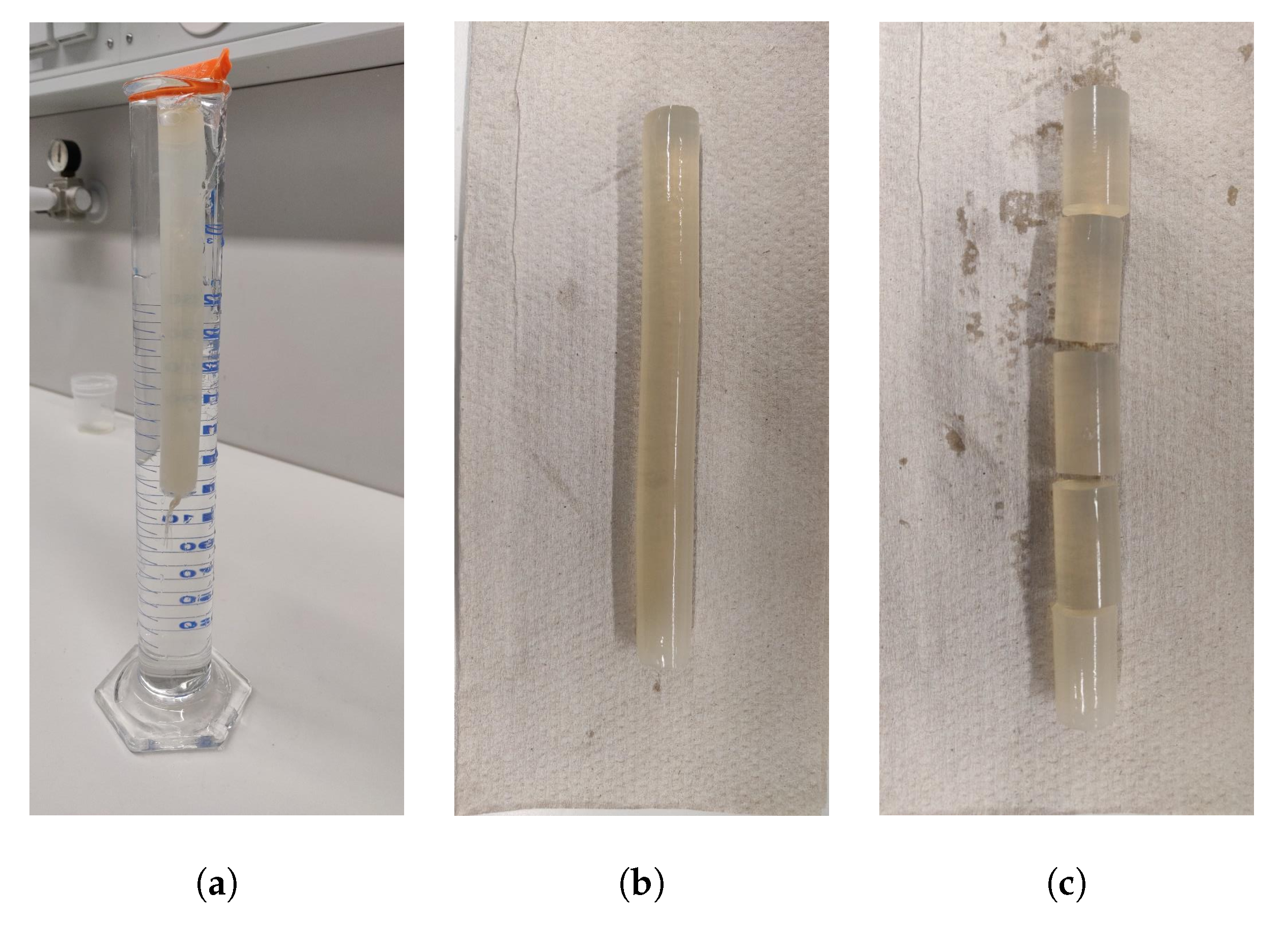
| (a) | (b) | (c) |


| (a) | (b) | (c) |


| (a) | (b) |

| Structural Model | |
|---|---|
| Radius of particles [m] | 152.5 |
| Radius of bonds [m] | 122.5 |
| Particles number | ≈99,000 |
| Number of solid bonds | ≈380,000 |
| Average bond length [m] | ≈370 |
| Functional model for bonds | |
| Compressive yield strain [%] | 3.52 |
| Plastic failure [-] | −0.3 |
| Interlocking stiffness factor [-] | 30 |
| Poisson ratio | 0.2 |
| Functional model for primary particles | |
| Poisson ratio | 0.2 |
| Friction coefficient | 0.1 |
| Rolling friction | 0.05 |
© 2019 by the authors. Licensee MDPI, Basel, Switzerland. This article is an open access article distributed under the terms and conditions of the Creative Commons Attribution (CC BY) license (http://creativecommons.org/licenses/by/4.0/).
Share and Cite
Dosta, M.; Jarolin, K.; Gurikov, P. Modelling of Mechanical Behavior of Biopolymer Alginate Aerogels Using the Bonded-Particle Model. Molecules 2019, 24, 2543. https://doi.org/10.3390/molecules24142543
Dosta M, Jarolin K, Gurikov P. Modelling of Mechanical Behavior of Biopolymer Alginate Aerogels Using the Bonded-Particle Model. Molecules. 2019; 24(14):2543. https://doi.org/10.3390/molecules24142543
Chicago/Turabian StyleDosta, Maksym, Kolja Jarolin, and Pavel Gurikov. 2019. "Modelling of Mechanical Behavior of Biopolymer Alginate Aerogels Using the Bonded-Particle Model" Molecules 24, no. 14: 2543. https://doi.org/10.3390/molecules24142543
APA StyleDosta, M., Jarolin, K., & Gurikov, P. (2019). Modelling of Mechanical Behavior of Biopolymer Alginate Aerogels Using the Bonded-Particle Model. Molecules, 24(14), 2543. https://doi.org/10.3390/molecules24142543