Article

Electrospun PVP/TiO2 Nanofibers for Filtration and Possible Protection from Various Viruses like COVID-19

1
School of Physics and Materials Science, Shoolini University of Biotechnology and Management Sciences, Solan 173212, India
2
Department of Civil and Environmental Engineering, University of California Los Angeles, Los Angeles, CA 90095, USA
3
Government Degree College Sujanpur Tihra, Sujanpur Tira 176110, India
4
Department of Physics, Guru Nanak Dev University, Amritsar 143005, India
*
Author to whom correspondence should be addressed.
Technologies 2021, 9(4), 89; https://doi.org/10.3390/technologies9040089
Submission received: 18 October 2021 / Revised: 9 November 2021 / Accepted: 15 November 2021 / Published: 19 November 2021

Abstract

:
In this study, TiO2 nanofibers were prepared with Polyvinylpyrrolidone (PVP) polymer using sol-gel method via electrospinning technique. Owing to the advantages of small fiber diameter, tunable porosity, low cost, large surface to volume ratio, structure control, light-weight, and less energy consumption, electrospun nanofibers are evolving as an adaptable material with a number of applications, in this case for filtration and environmental/virus protection. Different samples of TiO2/PVP nanofibers have been prepared by changing the parameters to achieve the best result. As the polymer concentration was increased from 6 to 8 wt.% of PVP, diameter of the resultant fibers was seen to be increased, implying decrease in the pore-size of the fibers up to 1.4 nm. Surface morphology has been checked via Scanning Electron Microscope (SEM) images. Crystalline nature has been analyzed by X-ray Crystallography. Using the Bruanauer-Emmett-Teller (BET) test, surface area and porosity has been checked for the suitable application. The synthesized TiO2/PVP nanofibers have tremendous practical potentials in filtration and environmental remediation applications.

1. Introduction

The 21st century, especially 2020, witnessed a great challenge to mankind due to the potential threat proposed by novel coronavirus. Along with various viruses being originated from time-to-time, other challenges for researchers are water and air filtration. Filtration by nanofiber membrane is comparatively a new method having a number of advantages due to its tunable properties. The nanofiber market worldwide is growing day by day for various applications. On 30 January 2020, the World Health Organization (WHO) declared a public health emergency of international concern over the 2019 novel coronavirus disease [1]. As a new dangerous virus, it attracts a lot of researchers towards it. Nature, in its most recent report, has stated that about 54 research papers were published by researchers all around the world, even by 30 January 2020 [2]. Now, it has broken all the borders, infecting more than 226,844,000 people worldwide. Globally, the deaths by this COVID-19 pandemic are 4,666,334 as of 14 September 2021 [3]. Due to the very small size of such high-risk viruses, researchers are looking towards nanotechnology solutions. Aleksandra Ivanoska-Dacikj and Urszula Stachewicz, in their recent review [4], has shown the importance and key role of non-pharmaceutical measures, in the initial moments, which are crucial in the containment of the spreading of any pandemic, as these are the cones that bridge the gap between pandemic outbreaks and the development of treatments or vaccinations, and they are critical in reducing the number of human lives lost. There is an urgent need of nano-porous materials which can protect mankind from such fast spread. The medical industry has explored various tools and protective materials, but some hazardous viruses and toxic elements cannot be stopped by ordinary filtration membranes. Nanofibrous compounds are excellent options for environmental remediation and face masks because of their abundance, low resistance, high surface area, stable chemical structure and excellent functionalization potential with other materials. By linking bioactive nanofiber characteristics with stimuli-responsive nanomaterials, [5] show how to create non-disposable and very comfortable respirators with light-triggered self-disinfection ability. Next-generation face masks must meet a set of core needs, including high filtration capabilities, increased comfort, moisture pump technology, and self-assisted disinfection capabilities. Along with this, the fine filtration membrane has other applications as well, like water, toxic gase, and air filtration as well as modern wound dressing membranes, etc. Electrospun nanofibers also play a vital role in fighting COVID-19, especially acting as drug carriers for biological molecules such as RNA [6]. Novel requests for the development of RNA-based vaccines that emerged during the COVID-19 pandemic have brought this technology into the spotlight.
70% of our planet is covered by water, however only 6% of world’s water is freshwater, out of which two-thirds is in glaciers, which is frozen, therefore, availability of fresh water is very low [7,8]. Due to the low availability of fresh and clean water, the world is facing a lot of problems. Water pollution is the leading worldwide cause of death and diseases. “About 1.2 billion people lack access to clean drinking water, 2.6 billion people have bad sanitation, and millions of people die each year from diseases spread by polluted water or human excreta” [7,8]. According to projections, the world population would reach 9 million by 2050, with 75 percent of the population facing a clean, fresh water shortage by 2075 [9]. Furthermore, wastewater is becoming more contaminated and difficult to treat as a result of rapid advancements in industrial technology and ineffective environmental policies [10]. Solving this problem requires enquiry into innovative methods of water filtration with less energy consumption and lower cost, so that there is reduction in the influence on the environment. Many technologies like reverse osmosis, distillation, chlorination, and coagulation have been used for water filtration previously. But none of them have the ability to remove impurities that range in the nanoscale. Although traditional filtering mediums have a high filtration efficiency, their performance is still poor for nanometer sized environmental remediation. So, there is a new method called membrane filtration, which is emerging these days for filtration. It has a number of advantages like less power consumption, freedom from chemicals, scalability, and the ability to run on lower temperatures [11]. The membrane acts as a medium that allows some molecules to pass through it and does not allow others, depending upon the size of the molecules and porosity of the membrane. Incorporating a nanofibrous medium into membrane filtration will increase it even further. Saurabh Kansara et al. [12], in their recent work, has fabricated carbonized composite fibers with transition metal oxides like nickel oxide, iron oxide, and titanium oxide. A Vis-UV spectrometer was used to analyze the finished product for adsorption of the dye Rhoda-mine B. The red-color dye, Rhodamine B, was successfully seen to be absorbed by the treated fiber, which contains transition metal oxides and activated carbon deposits. Similarly, Zhuojun Duan et al. [13], Wafa K. Essa et al. [14], and Samina Ghafoor et al. [15] have shown the application of nanofibers in elimination of toxic chemicals, in environmental remediation, NF based face masks, and water remediation, respectively.
Nanotechnology is concerned with the structure or method that can provide benefits derived from substances at the nanoscale, i.e., 10−9 m [16]. Nanofibers have a tiny fiber-like structure that cannot be seen by the naked eye; what we can see is only a reflection of light, and their real image can only be seen by an electron microscope. Nanofibers are part of the nanoworld where science is measured at around 1 billionth of a meter. They are already changing our life, giving new properties and things around us. A small drop of polymer solution is the starting point in the making of a nanofiber (NF). The drop is electrically charged in a high voltage electric field to give birth to nanofibers. The fibers are layered over each other, resulting in a nanofiber mat. We can get an idea of the small size of NFs by comparison with bacteria, which are unable to penetrate through a nanofibrous mat, as the pore size of the mat is much smaller than the size of a bacteria. NFs are thus capable of protecting us from bacteria and viruses. A nanofibrous membrane can stop water from passing through, such as through clothes, where drops of water slip away on the mat’s surface. However, textile materials of NFs are very breathable, because air molecules can get through the membrane easily. For example, a NF breathing mask can prevent bacteria from getting inhaled, yet at the same time allows comfortable breathing. There are hundreds of NFs applications. Owing to their specific characteristics, NFs are a revolutionary material for the third millennium. Nanofibers are fibers with a diameter of less than a 100 nm. NFs can be made from a variety of polymers and other molecules, and thus have a variety of physical properties and applications. Covalent bonds are the bonds by which polymer chains are bound together [17]. In comparison to their microfiber counterparts, all polymer nanofibers have a wide surface to volume ratio, appreciable mechanical strength, high porosity, and versatility in functionalization [18]. The diameter of the nanofiber is determined by the type of polymer used and the manufacturing process. Electrospinning, drawing, template synthesis, self-assembly thermal-induced phase separation and force spinning are some of the methods used to make nanofibers.
The nanofiber market worldwide is growing day by day for various applications. Many materials like TiO2, CuO, Fe2O3, MnO2, SnO2, Sn, Si, Ti, Ba, Mn, Sb, Cu, Fe, NiCo2O4 [19], and many more, are explored by various researchers worldwide as nanofiber-based technology. There are many methods for using these nanoscale additives in membranes, the most common of which are the direct addition of the nanomaterials to the solution used as a precursor for electrospun fibers and the immersion of membranes surfaces in a reactive formulation containing the nano-additives. Direct introduction of nano-additives into the nanofiber content appears to increase the performance of the final filters, because it prevents the pores being blocked by a subsequent coating [20]. Titanium dioxide is classified as a family of transition metal oxides, also called titanium (IV) oxide. It’s a flexible material with a wide range of uses, including protective surface coatings, sensors, cosmetics, solar cells, paints, water treatment, batteries, and many more [21,22,23]. High chemical stability, low-cost-production, non-toxicity, and biodegradability are all important features of this material. Titanium dioxide has the property to filter arsenic which is among one of the main impurities found in water, mainly in underground water.
Keeping the above issue in mind, we planned a systematic study on the fabrication and characterization of PVP/TiO2 nanofibers. In this communication, after preparation and characterization, porosity and other obtained results were correlated for potential application of such nanofibers for filtration and protection from various viruses.

2. Materials and Methods

2.1. Materials

Polyvinylpyrrolidone (PVP) (Mw~1,300,000 by LS) was chosen as the polymeric material for the preparation of TiO2 based nanofibers, because it is widely used in water treatment applications and has a high mechanical performance. It is also hydrophilic in nature, allowing it to easily handle membranes and its direct use as a filter in the decontamination process. PVP, Titanium (IV) isopropoxide (TTIP), Ethanol, and Acetic Acid were of analytical grade, purchased from Sigma Aldrich, Merck, India, and were used without further purification.

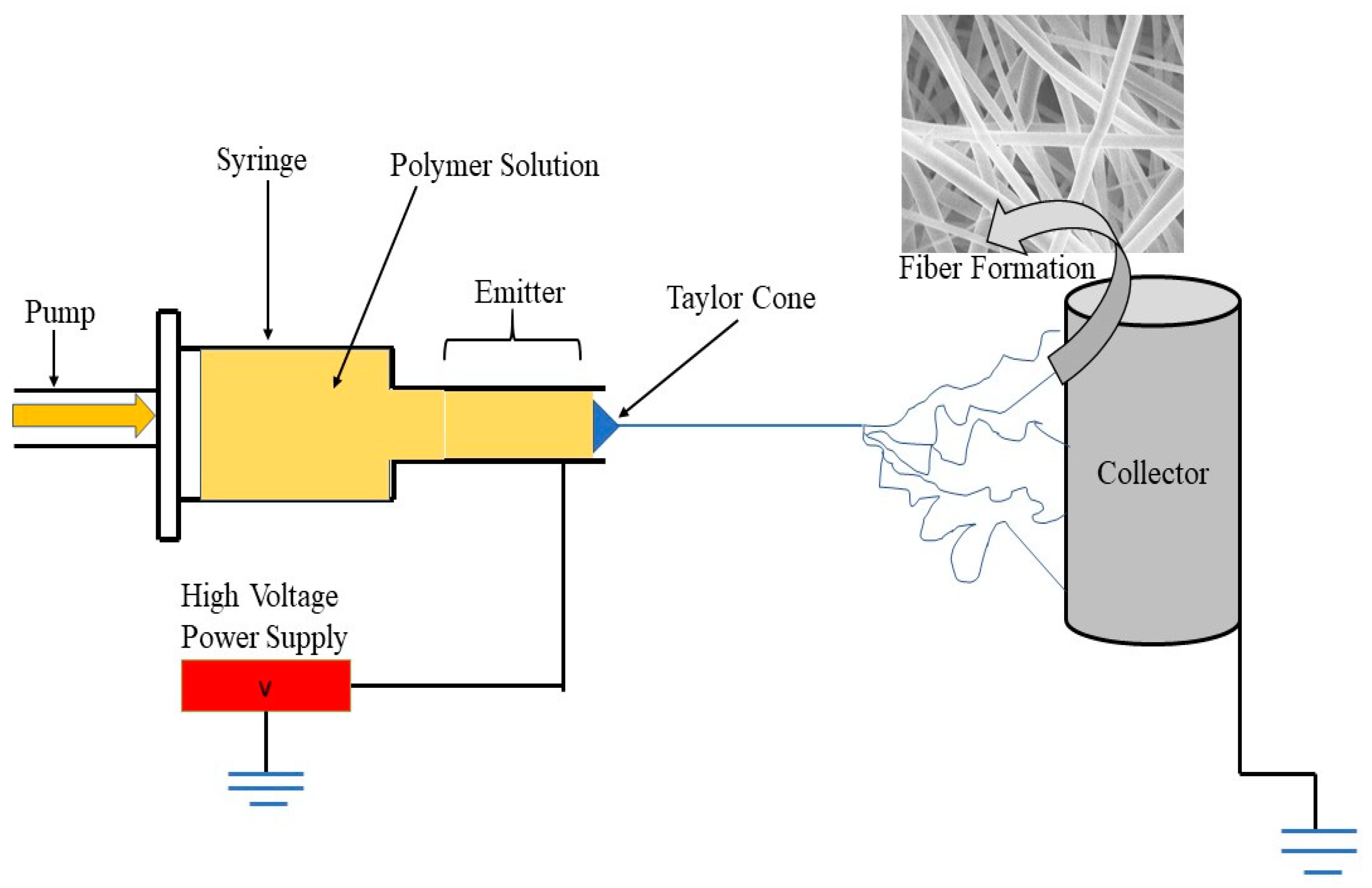
2.2. Electrospinning Setup

The most popular method of fabricating nanofibers is electrospinning [24,25,26]. A capillary tube with a small diameter needle, a high voltage source, and a collecting screen are all the instruments needed for electrospinning [27]. Figure 1 depicts the schematic diagram of an electrospinning setup. One electrode is connected to the collecting screen and another one is connected to the syringe in which a polymer solution is filled. An electric field is then applied across the electrodes, and the syringe or capillary tube, in which the polymer solution is kept in its place by its surface tension, starts forming a charge on the liquid’s surface. The hemispherical surface of the polymer solution at the tip of the syringe elongates as the electric field strength increases, and a conical shape is created which is known as a Taylor Cone. With the further increase in the value of the electric field, a critical value is reached. Upon reaching the critical value, the surface tension of the polymer solution gets overcome by the electrostatic force, which is repulsive in nature to it, and the charged polymer solution starts to eject from the tip of the Taylor cone. Due to the instability of the discharged polymer solution, it elongates, resulting in a jet, and becomes very long and thin [11,17]. Nanofibers, having random orientation, are collected over the metal collector. To collect highly aligned nanofibers, a special kind of collectors can be used, such as metal frame, rotating drum, and a system which has two parallel plates [19,20,24]. To obtain nanofibers having uniform diameter and an aligned morphology, different parameters such as concentration of the polymers and flow rate have to be controlled [25]. Different kinds of polymers can be converted into nanofibers using this method.

2.3. Preparation of the TiO2 Solution

For the development of PVP/TiO2 electrospun nanofibers, a 6, 7 & 8 wt.% of PVP was mixed in 1:2:2 ratio of the three different solutions of TTIP, Ethanol and Acetic Acid respectively with the help of magnetic stirring for approximately 45 min.
The electrospinning machine, which we used for the production of nanofibers, was single jet, i.e., there was only one source from which the polymer solution was ejected. The various conditions to manufacture nanofibers were set in such a way that resulting nanofibers could have a diameter in the ideal range for the desired applications, and also so tht the fibers produced would be free from defects like excess solvent and beads. The removal of these defects is necessary, because they can easily affect the adsorption capability of the resulting fibers. Temperature and humidity also plays a major role on the structure of the electropun NFs [28], so the as-fabricated fibers were synthesized at room temperature (25 °C), and humidity was kept at around 40% during the fabrication of the NFs. Thus, we obtained defect free nanofibers having diameters within the acceptable range of the desired applications. The distance between the syringe and the rotating drum, i.e., collector, was 18 cm, while the drum was rotated at 350 rotations per minute. We had to set the voltage for which the Taylor cone would become elongated and overcome the surface tension: for this case it was 11.0 kV. All these parameters were set, and we electrospun a single sample for about 5 h, following previous optimization conditions to avoid the variation in viscosity due to the evaporation of the solvent. All these values were set due to the high molecular weight of TTIP, which is about 1,300,000 g/mol, due to which pairing of chains is ensured even at the low concentration of the solution [25,29]. Different weight percentages of polymer were taken to make the solution. The different values to make the solution are given in Table 1 and Table 2.
After the preparation of the TiO2/PVP solution the nanofibers were prepared through electrospinning by using the precursor solution.

2.4. Characterization

The nanofiberous membrane was taken out and subjected to the characterization process. Surface morphology was examined using a Carl Zeiss field emission scanning electron microscope (Supra 55), installed at GNDU Amritsar to study the diameter and porosity of the fibers. X-ray Crystallography was carried out by “Rigaku corporation SmartLab® (Tokyo, Japan), 9 kW rotating anode X-ray diffractometer Philips” by using 2θ = 20–80° with CuKα radiation (wavelength, λ = 1.5418 Å) for the crystalline analysis of the resultant fibers, and BET was done by Quantachrome® ASiQwin™(Graz, Austria) Autosorb iQ Station 1 for surface area and porosity analysis, installed at IIT-Mandi, India.

3. Results and Discussion

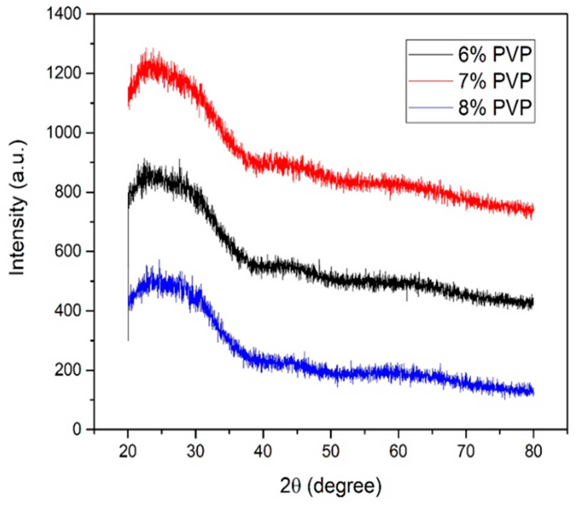
3.1. X-ray Analysis of TiO2/PVP Nanofibers

X-ray diffraction (XRD) measurement was carried out to investigate the crystalline nature of uncalcinated TiO2/PVP Nanofibers. TTIP is hydrolyzed in the early phases of electrospinning by reacting with moisture in the air to create ultrafine amorphous TiO2 particles in the PVP matrices. The crystallinity of the polymeric host could be affected by the inclusion of impurities when a polymer is complexed with a salt. It revealed the presence of false diffraction peaks and other detectable reflection patterns in the material [30]. Between angles 2θ = 25 and 45, a diffraction hump was found, which is due to the semicrystallinity of uncalcinated PVP-TiO2 nanofibers. With respect to PVP in salt TTIP, the relative intensity of the hump diminishes, while its broadness grows. This suggests that adding PVP diminishes the crystalline nature of PVP while increasing the amorphous nature. As a result of the complexation between PVP and TTIP, no peaks were observed, indicating that the salt was completely dissociated in polymer matrices. Figure 2 depicts the XRD patterns of TiO2/PVP nanofibers at 6, 7 and 8 wt.% of PVP respectively. There is no appearance of a diffraction peak in the XRD pattern of uncalcinated TiO2 nanofibers. No appearance of a diffraction peak indicates the amorphous nature of uncalcinated TiO2/PVP nanofibers [31]. These results are in agreement with M.V. Someswararao et al. [32], where amorphous nature of as-prepared nanofibers is predicted by XRD, which further can be transformed to a crystalline state by calcination and annealing.

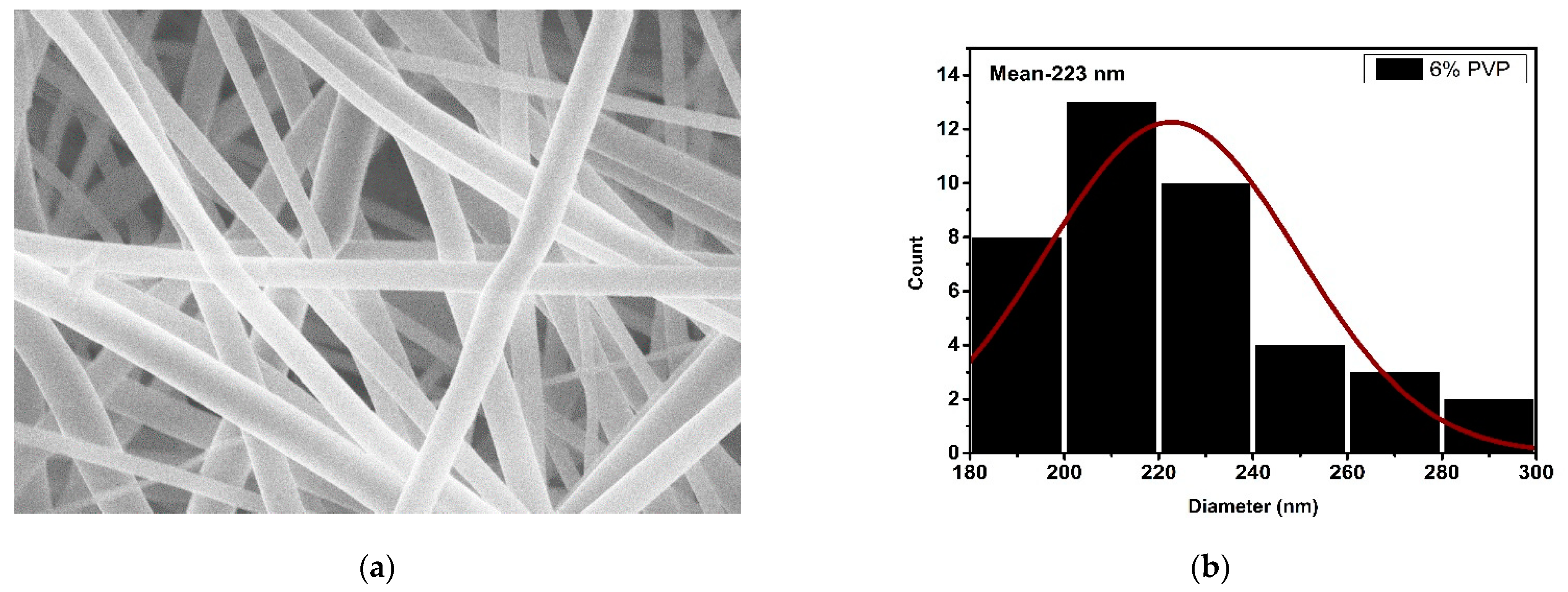
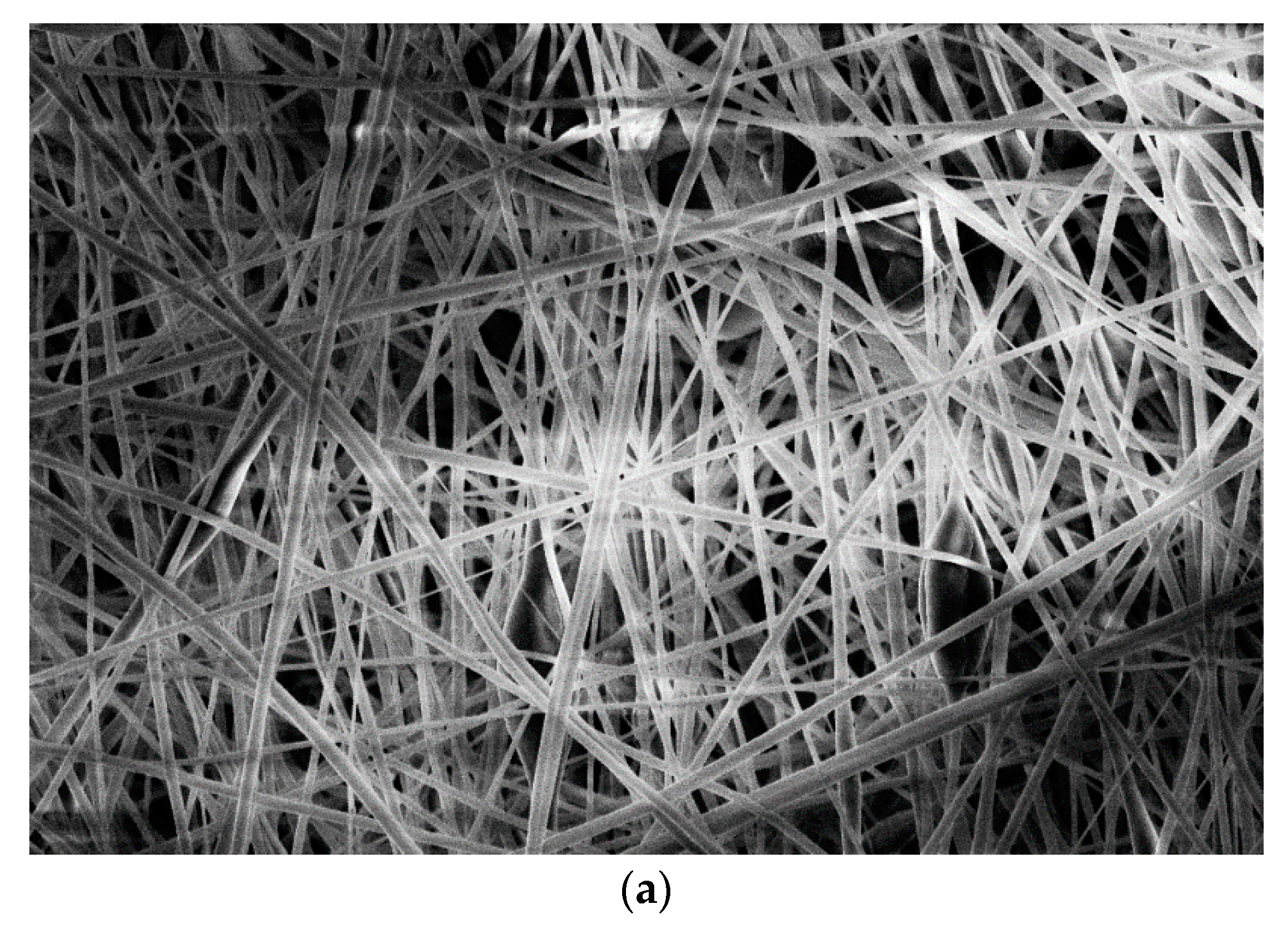
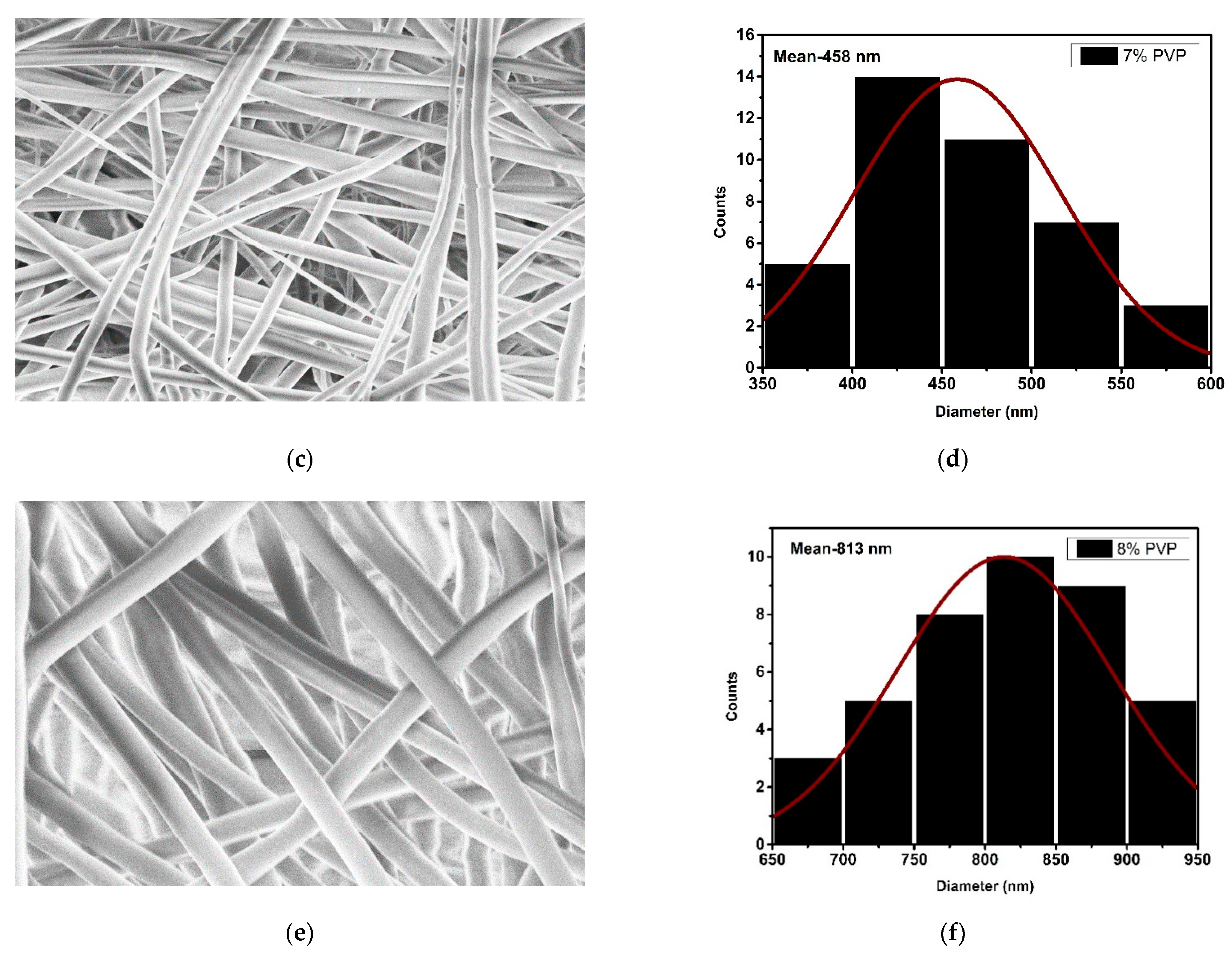
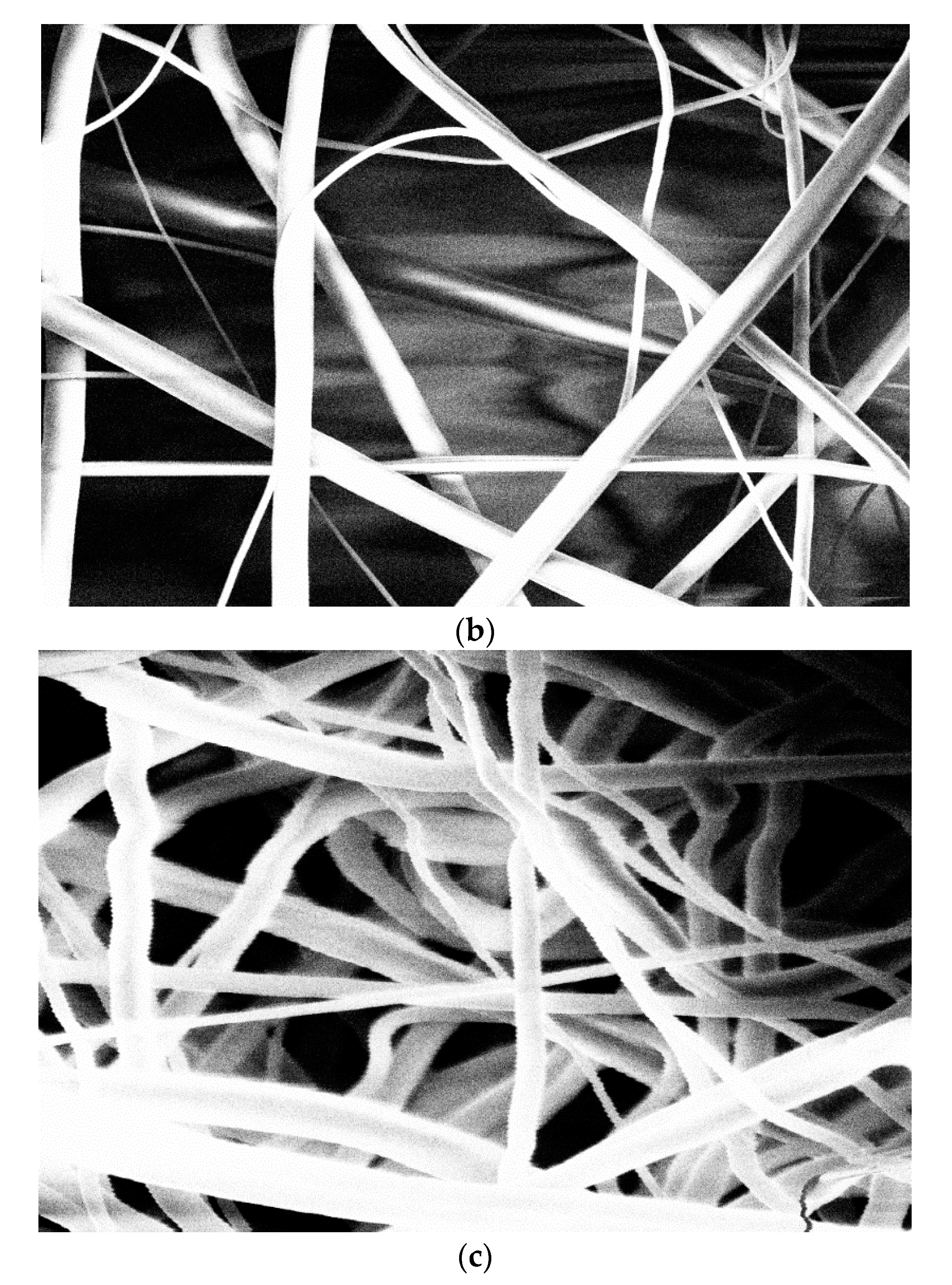
3.2. Microscopic Analysis

The surface morphologies of the samples were examined using a ZEISS Gemini SEM scanning electron microscope at a voltage of 5.0 kV and a magnification of 10.00 K X. To remove the charging effect, the electrospun fibers were coated with silver target to be electrically conductive and to get clear images.
The surface morphology and diameter of the uncalcinated PVP/TiO2 nanofibers were analyzed by using SEM, as shown in Figure 3. It was observed from Figure 3 that the resultant nanofibers have a smooth surface and are of a straight, uniform, beadless formation and have random orientation. Figure 4 shows the high magnification images of nanofibers taken by the SEM of samples prepared by electrospinning at (i) 6, (ii) 7 and (iii) 8% wt.% of PVP/TiO2 solution for porosity analysis. Because the polymer chain of PVP is related to the viscosity of the solution, raising the concentration of the polymer PVP increases the viscosity of the precursor solution [33]. The viscosity of the precursor solution is affected by the weight percent of polymer PVP. The low viscous solution has a low visco-elasticity and a low electrostatic force, making it unsuitable for electrospinning. The solution’s high viscosity provides homogeneous, smooth fibers with no bead formation, while a substantial increase in viscosity causes instability in the nanofibrous jet [34]. As a result, the solution has a high electrostatic force during nanofiber synthesis, resulting in homogeneous and smooth nanofibers [35]. The diameter and pore size of the NFs was examined via SEM images with the help of ImageJ. Each single fiber was measured once, and the spot in the fiber for measurement was randomly selected. The total number of measurements on one sample ranged from 60 to 80, and measured data was saved and analyzed to calculate the diameter and pore size of the fibers. As the pore size measurement via 2D-SEM images are not very accurate, these measurements were done to correlate with the more accurate pore size analysis via the BET method. The mean diameter at 6% PVP concentration was around 223 nm. At 7% and 8% of PVP the mean fiber diameter was observed at around 458 nm and 813 nm, respectively. We see that, as the concentration of polymer increases, there is an increase in the diameter of the nanofibers. The concentration of polymer has a major role in the defining properties of the resulting fibers. All the conditions were kept the same, and when the concentration of the polymer was changed, the diameter was seen to be increased with an increase in the concentration of the polymer. The surface area of the nanofiber decreases as the diameter of the nanofiber increases, gradually. “A non-linear curve was the result when Dietzel et al., were examining the relationship between diameter of the fiber and concentration of the solution” [36]. This non-linear relationship between the diameter of the fiber and the concentration of the solution can be explained by the non-linear relationship between the viscosity of the solution and the concentration of polymer [37]. Depending on the solution concentration, the viscosity of the solution changes. High concentration of polymer solution increases the solution viscosity due to higher number of polymer chain entanglement. Low viscous solution results in beaded fibers. Therefore, higher polymer concentration in the solution means higher viscosity, which results in fibers having no beads. This shows that the higher viscosity of the solution correlates to a greater uniformity of the resultant fibers. Therefore, higher polymer concentration in the solution means higher viscosity, which results in bead free fibers. All bacteria such as coliform, E coli., giardia, salmonella, and other water-borne microorganisms that can cause diseases like flu, polio, typhoid fever, and tetanus are practically eliminated by nanomembranes. The amount of contaminant, the degree of contaminant, and the size of contaminant particles all play a role in contaminant filtration. As a result, nanofibrous membranes are predominantly used in the processing of drinking water, as well as the treatment of industrial water. Also, such fine nanoporous fibers, with porosity less than 10 nm, make them suitable for filtration and use in protective masks from various viruses like COVID-19.
Table 3 shows the variation of diameter and porosity of nanofibers with the change in the concentration of polymer done by SEM.

3.3. Surface Area and Porosity Analysis

The BET method aims to find accurate surface area, porosity, and pore volume in nanoporous materials. Developed by Paul Hugh Emmett, Stephen Brunauer, and Edward Teller in 1938, the system allows adsorption and desorption of gases that do not react with materials under investigation [38]. We analyzed our TiO2/PVP nanofibers by BET using Nitrogen gas as absorbent.

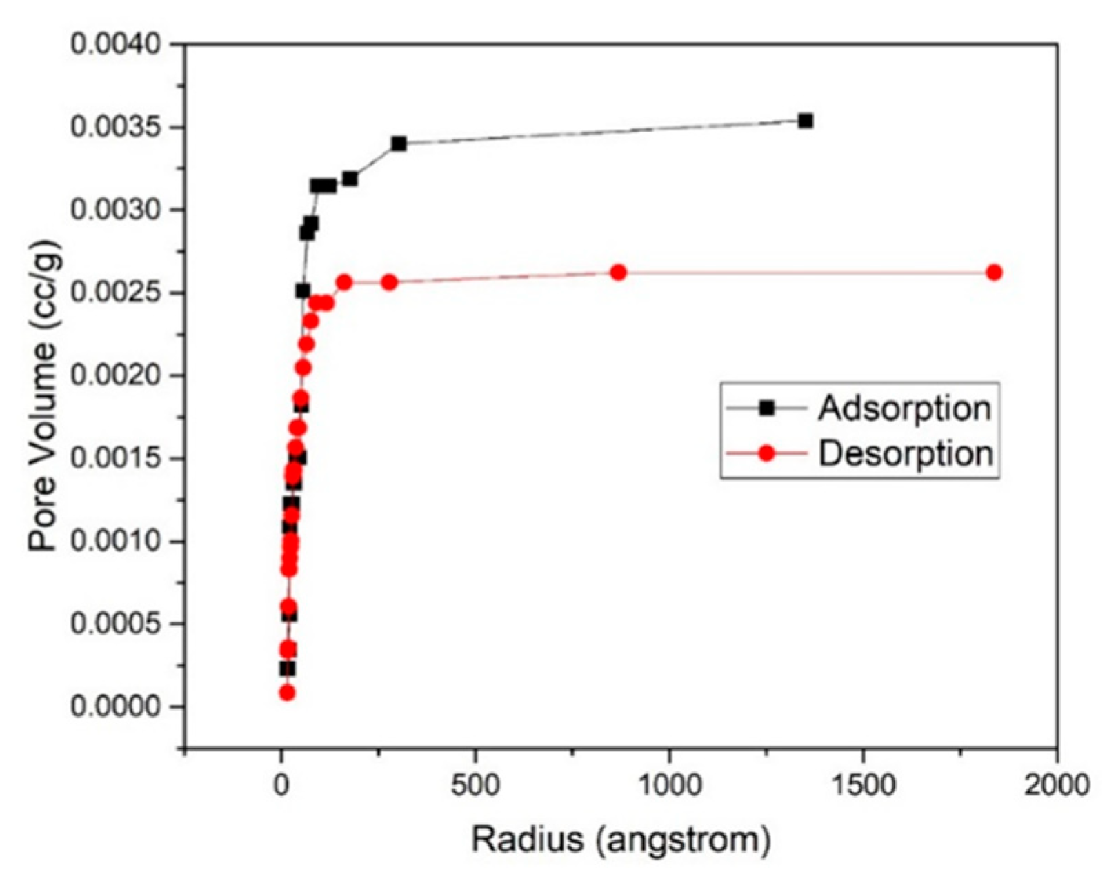
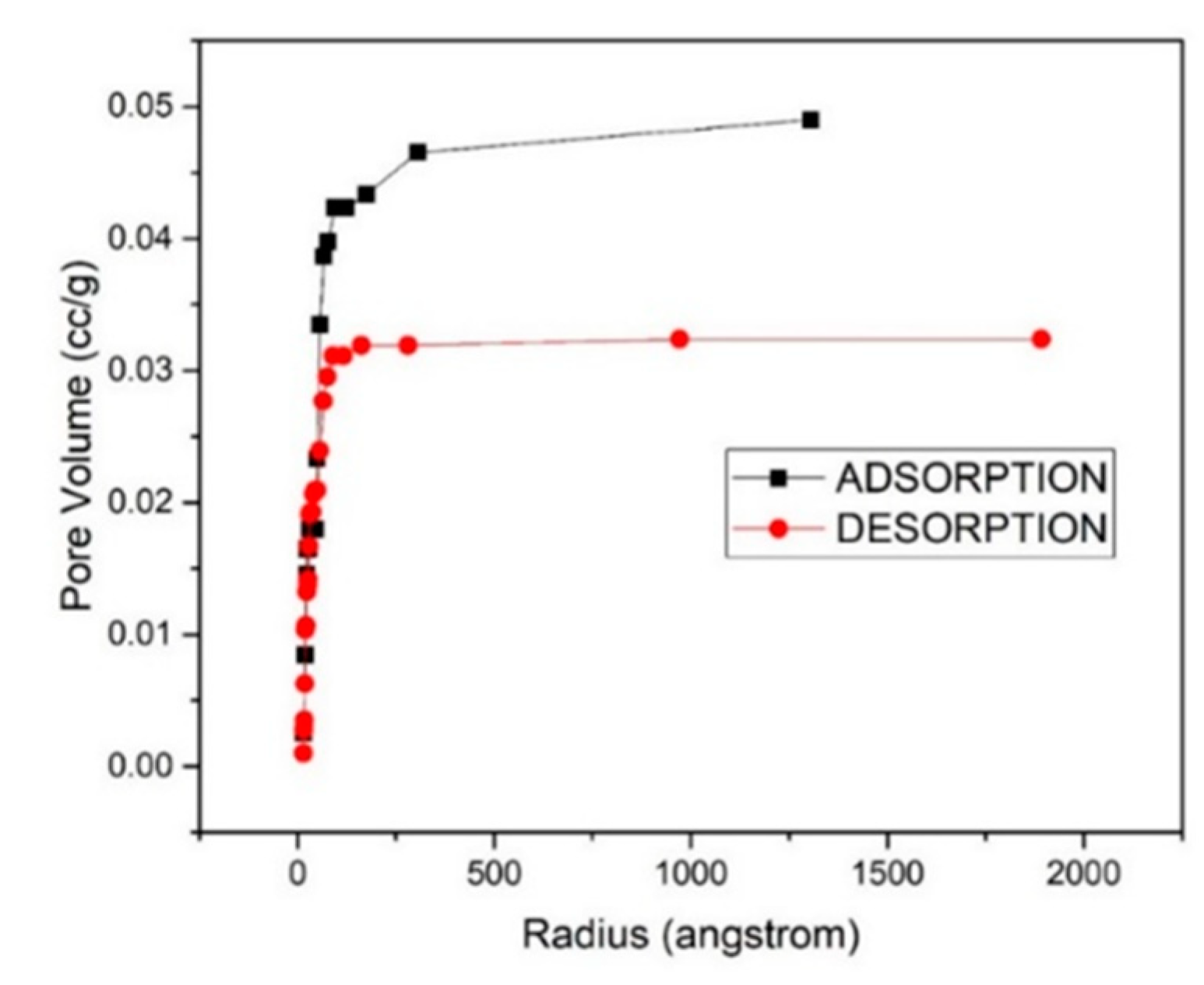
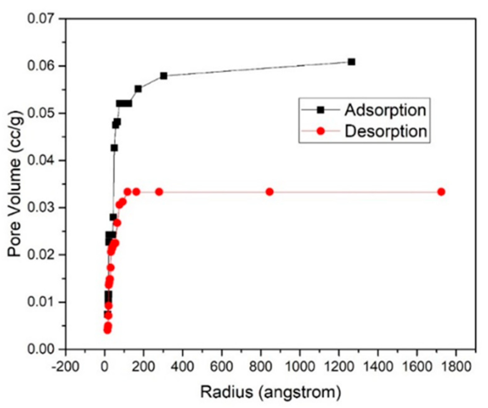
3.4. Adsorption-Desorption Curve

Figure 5, Figure 6 and Figure 7 show the adsorption-desorption curve for as-prepared nanofibers with 6%, 7%, and 8% PVP concentration, respectively. Both adsorption and desorption curves were analyzed together. As seen from the graphs, the adsorption curve is left of the desorption one. Upon desorption, part of the adsorbent is not saturated at the respective relative pressure, so it adsorbs more instead of desorbing, which results in the observed maximum.
The pore radius vs. pore volume graph shows that maximum pores are in the range of 1–5 nm. A straight line is observed initially, showing that the maximum pore volume has a radius ranging from 1–5 nm. The gap in between the adsorption and desorption curve is because more gas is adsorbed on the surface and less gets desorbed due to the accumulation of gas in between the pores. It adsorbs more instead of desorbing, which results in the observed maximum.
Table 4 compares the porosity (nm), surface area (m2/g), and pore volume (cc/g) with the change in the concentration of the polymer, calculated by BET analysis.
Table 5 sums up the obtained porosity by our research work and porosity for various applications where it can be used for the development of ENM.
It has been analyzed that with an increase in the polymer concentration, there is a decrease in the porosity of the fibers, i.e., the fibrous membrane becomes less porous with an increase in the polymer concentration. This can be explained by the increase in the chain entanglement of the fibers as the polymer concentration rises, due to an increase in the viscosity of the solution. These results are in correlation with SEM data, where with the increase in wt.% of PVP concentration an increase in diameter is observed. Such fine porosity in nm scale project these TiO2/PVP nanofibers as a potential candidate for water-air filtration and various other protective membrane solutions for saving mankind from various viruses like SARS-COV, Ebola, COVID-19, SARS-CoV-CoV-2, Bird-flu, Zika, Marburg and Hantavirus.

4. Conclusions

In this communication, we studied the effect of different weight percentage concentrations of PVP in uncalcinated TiO2 Nanofibers. Electrospun nanofibers of PVP, loaded with TiO2, were successfully fabricated with PVP weight concentrations of 6%, 7%, and 8%. All spun fibers were completely amorphous in nature, as observed by XRD. SEM images suggests nanofibers were flat with smooth surface and clearly show the increase in diameter with increase in the polymer concentration. BET analysis confirms the nano-porosity of the fibers, leading to a wide range of potential applications. The fibers’ porosity, ranging from 1.44 nm to 4.08 nm, was successfully achieved. This enables the resultant fibers to have various applications ranging from filtration of water, air filtration, and use in protection masks from various environmental hazards like SARS-COV and COVID-19, etc.

Author Contributions

A.S. performed experiments, data analysis, interpretation and prepared the manuscript, D.P. contributed to developing the research design and supervised this overall work. V.B., A.M., N.D. and D.S.P. helped in research analysis and experimental design. All the authors have edited and revised the manuscript. All authors have read and agreed to the published version of the manuscript.

Funding

This research received no external funding.

Institutional Review Board Statement

Not applicable.

Informed Consent Statement

Not applicable.

Data Availability Statement

Not applicable.

Conflicts of Interest

The authors declare no conflict of interest.

References

  1. WHO. Statement on the Second Meeting of the International Health Regulations (2005) Emergency Committee Regarding the Outbreak of Novel Coronavirus (2019-nCoV); World Health Organization: Geneva, Switzerland, 2020. [Google Scholar]
  2. Stoye, E. China coronavirus: How many papers have been published? Nature 2020. [Google Scholar] [CrossRef] [PubMed]
  3. WHO Coronavirus (COVID-19) Dashboard. 2021. Available online: Covid19.who.int (accessed on 14 September 2021).
  4. Ivanoska-Dacikj, A.; Stachewicz, U. Smart textiles and wearable technologies–opportunities offered in the fight against pandemics in relation to current COVID-19 state. Rev. Adv. Mater. Sci. 2020, 59, 487–505. [Google Scholar] [CrossRef]
  5. De Sio, L.; Ding, B.; Focsan, M.; Kogermann, K.; Pascoal-Faria, P.; Petronela, F.; Mitchell, G.; Zussman, E.; Pierini, F. Personalized reusable face masks with smart nano-assisted destruction of pathogens for COVID-19: A visionary road. Chem.–A Eur. J. 2021, 27, 6112–6130. [Google Scholar] [CrossRef] [PubMed]
  6. Rinoldi, C.; Zargarian, S.S.; Nakielski, P.; Li, X.; Liguori, A.; Petronella, F.; Presutti, D.; Wang, Q.; Costantini, M.; De Sio, L.; et al. Nanotechnology-assisted RNA delivery: From nucleic acid therapeutics to COVID-19 vaccines. Small Methods 2021, 5, 2100402. [Google Scholar] [CrossRef]
  7. Montgomery, M.A.; Elimelech, M. Water and sanitation in developing countries: Including health in the equation. Environ. Sci. Technol. 2007, 41, 17–24. [Google Scholar] [CrossRef]
  8. Shannon, M.A.; Bohn, P.W.; Elimelech, M.; Georgiadis, J.G.; Marinas, B.J.; Mayes, A.M. Science and technology for water purification in the coming decades. Nanosci. Technol. A Collect. Rev. Nat. J. 2010, 452, 337–346. [Google Scholar]
  9. Tlili, I.; Timoumi, Y.; Nasrallah, S.B. Numerical simulation and losses analysis in a Stirling engine. Int. J. Heat Technol. 2006, 24, 97–105. [Google Scholar]
  10. Dersch, R.; Liu, T.; Schaper, A.K.; Greiner, A.; Wendorff, J.H. Electrospun nanofibers: Internal structure and intrinsic orientation. J. Polym. Sci. Part A Polym. Chem. 2003, 41, 545–553. [Google Scholar] [CrossRef]
  11. Kim, K.W.; Lee, K.H.; Khil, M.S.; Ho, Y.S.; Kim, H.Y. The effect of molecular weight and the linear velocity of drum surface on the properties of electrospun poly(ethylene terephthalate) nonwovens. Fibers Polym. 2004, 5, 122–127. [Google Scholar] [CrossRef]
  12. Kansara, S.; Patel, S.; Gan, Y.X.; Jaimes, G.; Gan, J.B. Dye adsorption and electrical property of oxide-loaded carbon fiber made by electrospinning and hydrothermal treatment. Fibers 2019, 7, 74. [Google Scholar] [CrossRef] [Green Version]
  13. Duan, Z.; Huang, Y.; Zhang, D.; Chen, S. Electrospinning fabricating Au/TiO2 network-like nanofibers as visible light activated photocatalyst. Sci. Rep. 2019, 9, 8008. [Google Scholar] [CrossRef]
  14. Essa, W.; Yasin, S.; Saeed, I.; Ali, G. Nanofiber-based face masks and respirators as COVID-19 protection: A review. Membranes 2021, 11, 250. [Google Scholar] [CrossRef] [PubMed]
  15. Ghafoor, S.; Aftab, F.; Rauf, A.; Duran, H.; Kirchhoff, K.; Arshad, S.N. P-doped TiO2 nanofibers decorated with Ag nanoparticles for enhanced photocatalytic activity under simulated solar light. ChemistrySelect 2020, 5, 14078–14085. [Google Scholar] [CrossRef]
  16. Almutairi, M.M.; Osman, M.; Tlili, I. Thermal behavior of auxetic honeycomb structure: An experimental and modeling investigation. J. Energy Resour. Technol. 2018, 140, 122904. [Google Scholar] [CrossRef]
  17. Teraoka, I. Polymer Solutions: An Introduction to Physical Properties; John Wiley & Sons, Inc.: Brooklyn, NY, USA, 2002. [Google Scholar]
  18. Hao, Y.; Feng, Z.; He, Z.; Zhang, J.; Liu, X.; Qin, J.; Guo, L.; Bi, K. Gradient design of ultrasmall dielectric nanofillers for PVDF-based high energy-density composite capacitors. Mater. Des. 2020, 189, 108523. [Google Scholar] [CrossRef]
  19. Arumugam, V.; Moodley, K.G. Mixed metal and metal oxide nanofibers: Preparation, fabrication, and applications. In Handbook of Nanofibers; Barhoum, A., Bechelany, M., Makhlouf, A., Eds.; Springer International Publishing: Cham, Switzerland, 2019. [Google Scholar]
  20. Geltmeyer, J.; Teixido, H.; Meire, M.; Van Acker, T.; Deventer, K.; Vanhaecke, F.; Van Hulle, S.; De Buysser, K.; De Clerck, K. TiO2 functionalized nanofibrous membranes for removal of organic (micro)pollutants from water. Sep. Purif. Technol. 2017, 179, 533–541. [Google Scholar] [CrossRef] [Green Version]
  21. Park, J.-Y.; Lee, I.-H. Relative humidity effect on the preparation of porous electrospun polystyrene fibers. J. Nanosci. Nanotechnol. 2010, 10, 3473–3477. [Google Scholar] [CrossRef]
  22. Park, J.-Y.; Hwang, K.-J.; Lee, J.-W.; Lee, I.-H. Fabrication and characterization of electrospun Ag doped TiO2 nanofibers for photocatalytic reaction. J. Mater. Sci. 2011, 46, 7240–7246. [Google Scholar] [CrossRef]
  23. Pan, H.; Feng, Y.P. Semiconductor nanowires and nanotubes: Effects of size and surface-to-volume ratio. ACS Nano 2008, 2, 2410–2414. [Google Scholar] [CrossRef]
  24. Lolla, D.; Gorse, J.; Kisielowski, C.; Miao, J.; Taylor, P.L.; Chase, G.G.; Reneker, D.H. Polyvinylidene fluoride molecules in nanofibers, imaged at atomic scale by aberration corrected electron microscopy. Nanoscale 2016, 8, 120–128. [Google Scholar] [CrossRef] [Green Version]
  25. Li, D.; Xia, Y. Electrospinning of nanofibers: Reinventing the wheel? Adv. Mater. 2004, 16, 1151–1170. [Google Scholar] [CrossRef]
  26. Monteserín, C.; Blanco, M.; Murillo, N.; Pérez-Márquez, A.; Maudes, J.; Gayoso, J.; Laza, J.M.; Aranzabe, E.; Vilas, J.L. Effect of different types of electrospun polyamide 6 nanofibres on the mechanical properties of carbon fibre/epoxy composites. Polymers 2018, 10, 1190. [Google Scholar] [CrossRef] [PubMed] [Green Version]
  27. Jamnongkan, T.; Wattanakornsiri, A.; Pansila, P.P.; Migliaresi, C.; Kaewpirom, S. Effect of poly(vinyl alcohol)/chitosan ratio on electrospun-nanofiber morphologies. Adv. Mater. Res. 2012, 463-464, 734–738. [Google Scholar] [CrossRef]
  28. Mailley, D.; Hébraud, A.; Schlatter, G. A Review on the impact of humidity during electrospinning: From the nanofiber structure engineering to the applications. Macromol. Mater. Eng. 2021, 306, 2100115. [Google Scholar] [CrossRef]
  29. Sarbatly, R.; Krishnaiah, D.; Kamin, Z. A review of polymer nanofibres byelectrospinning and their application in oil-water separation for cleaning up marine oil spills. Mar. Pollut. Bull. 2016, 106, 8–16. [Google Scholar] [CrossRef]
  30. Lai, Y.; Meng, M.; Yu, Y.; Wang, X.; Ding, T. Photoluminescence and photocatalysis of the flower-like nano-ZnO photocatalysts prepared by a facile hydrothermal method with or without ultrasonic assistance. Appl. Catal. B Environ. 2011, 105, 335–345. [Google Scholar] [CrossRef]
  31. Hu, M.; Fang, M.; Tang, C.; Yang, T.; Huang, Z.; Liu, Y.; Wu, X.; Min, X. The effects of atmosphere and calcined temperature on photocatalytic activity of TiO2 nanofibers prepared by electrospinning. Nanoscale Res. Lett. 2013, 8, 548. [Google Scholar] [CrossRef] [Green Version]
  32. Someswararao, M.V.; Dubey, R.S.; Subbarao, P.S.V.; Singh, S. Electrospinning process parameters dependent investigation of TiO2 nanofibers. Results Phys. 2018, 11, 223–231. [Google Scholar] [CrossRef]
  33. Stefan, M.; Pana, O.; Leostean, C.; Bele, C.; Silipas, D.; Senila, M.; Gautron, E. Synthesis and characterization of Fe3O4–TiO2 core-shell nanoparticles. J. Appl. Phys. 2014, 116, 114312. [Google Scholar] [CrossRef]
  34. Tripathi, A.K.; Singh, M.K.; Mathpal, M.; Mishra, S.K.; Agarwal, A. Study of structural transformation in TiO2 nanoparticles and its optical properties. J. Alloys Compd. 2013, 549, 114–120. [Google Scholar] [CrossRef]
  35. Shen, J.; Wu, Y.-N.; Fu, L.; Zhang, B.; Li, F. Preparation of doped TiO2 nanofiber membranes through electrospinning and their application for photocatalytic degradation of malachite green. J. Mater. Sci. 2014, 49, 2303–2314. [Google Scholar] [CrossRef]
  36. Deitzel, J.M.; Kleinmeyer, J.; Harris, D.E.A.; Tan, N.B. The effect of processing variables on the morphology of electrospun nanofibersand textiles. Polymer 2001, 42, 261–272. [Google Scholar] [CrossRef]
  37. Lin, T.; Wang, X.G. Controlling the morphologies of electrospun nanofibers. In Nanofibers and Nanotechnology in Textiles; Woodhead Publishing: Sawston, UK, 2007; pp. 90–110. [Google Scholar]
  38. Brunauer, S.; Emmett, P.H.; Teller, E. Adsorption of gases in multimolecular layers. J. Am. Chem. Soc. 1938, 60, 309–319. [Google Scholar] [CrossRef]
Figure 1. Schematic diagram of electrospinning.
Technologies 09 00089 g001
Figure 2. XRD pattern of 6, 7 & 8 wt.% PVP/TiO2 Nanofibers.
Technologies 09 00089 g002
Figure 3. (a,c,e) represents FE-SEM images of (i) 6, (ii) 7 & (iii) 8 wt.% of PVP/TiO2 nanofibers and (b,d,f) represent their corresponding diameter histograms.
Technologies 09 00089 g003aTechnologies 09 00089 g003b
Figure 4. High magnification FESEM images of (a) 6, (b) 7 & (c) 8 wt.% of PVP/TiO2 nanofibers for pore-size analysis.
Technologies 09 00089 g004aTechnologies 09 00089 g004b
Figure 5. Adsorption-Desorption Curve 6% PVP.
Technologies 09 00089 g005
Figure 6. Adsorption-Desorption Curve 7% PVP.
Technologies 09 00089 g006
Figure 7. Adsorption-Desorption Curve 8% PVP.
Technologies 09 00089 g007
Table 1. PVP solution details.
Experiment No.PVP wt.%PVPEthanol (10 mL)Total
16%0.504 g7.9 g8.404 g
27%0.59 g7.9 g8.49 g
38%0.68 g7.9 g8.58 g
Table 2. TTIP solution details.
Experiment No.TiP-IVEthanolAcetic Acid
11 mL2 mL2 mL
21 mL2 mL2 mL
31 mL2 mL2 mL
Table 3. Diameter and Pore Size Analysis of as prepared PVP/TiO2 nanofibers by SEM.
Concentration of PVPDiameter (nm)Pore Size (nm)
6%2234.045
7%4582.827
8%8131.664
Table 4. Surface Area, Pore Size and Pore Volume Analysis by BET.
Concentration of PVPSurface Area (m2/g)Pore Size (nm)Pore Volume (cc/g)
AdsorptionDesorption
6%26.05621.9744.08720.03232
7%1.9611.7772.747090.00208
8%36.70022.6551.447050.02266
Table 5. Various potential applications where nanofibers can be used.
Various Elements and VirusesSize (nm)
Obtained Pore Size1.44 nm, 2.74 nm, 4.08 nm
Size of toxic elements in water
(Arsenic, Cobalt, Mercury, Cadmium, Nickel, Chromium, Lead)
0.121 nm to 0.175 nm
Size of Water Molecule0.275 nm
Size of Ar, N & O0.363 nm, 0.305 nm, 0.299 nm
Size of toxic elements in air
(Asbestos, Mercury, Cadmium, Chromium)
0.127 to 0.157 nm
Size of few harmful viruses
(Ebola, COVID-19, SARS-COV-CoV, Bird-flu, Zika, Marburg, Hantavirus)
50–140 nm
Publisher’s Note: MDPI stays neutral with regard to jurisdictional claims in published maps and institutional affiliations.

