
Resilient Response of Cement-Treated Coarse Post-Glacial Soil to Cyclic Load


Abstract
1. Introduction
2. Materials and Methods
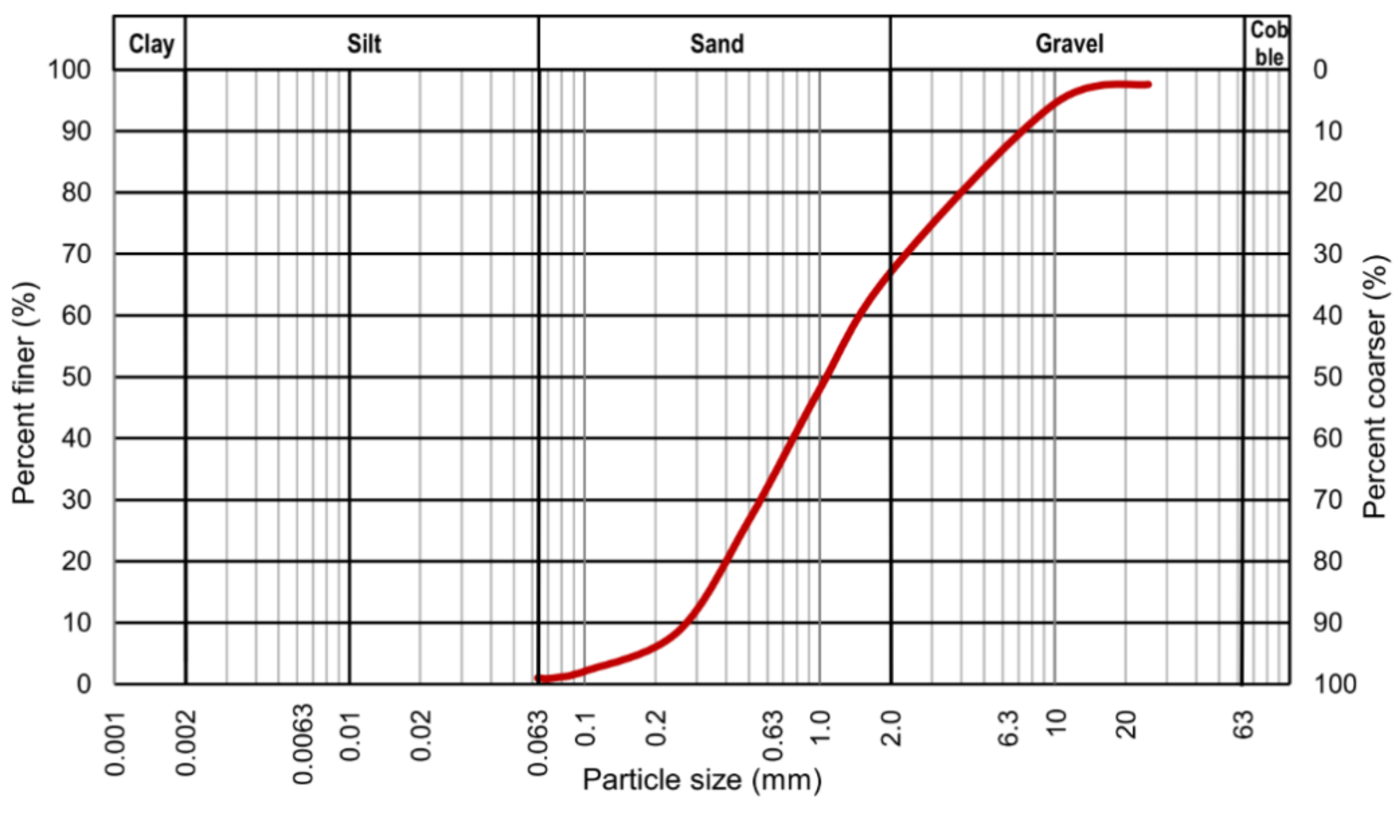
2.1. Materials
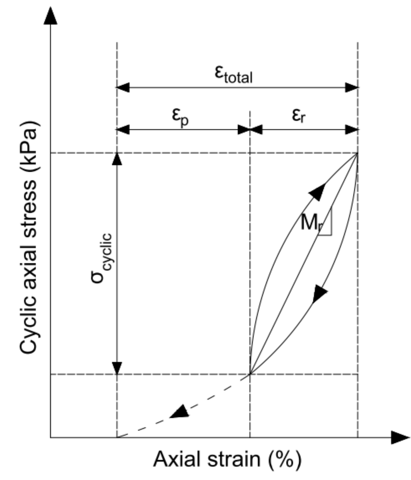
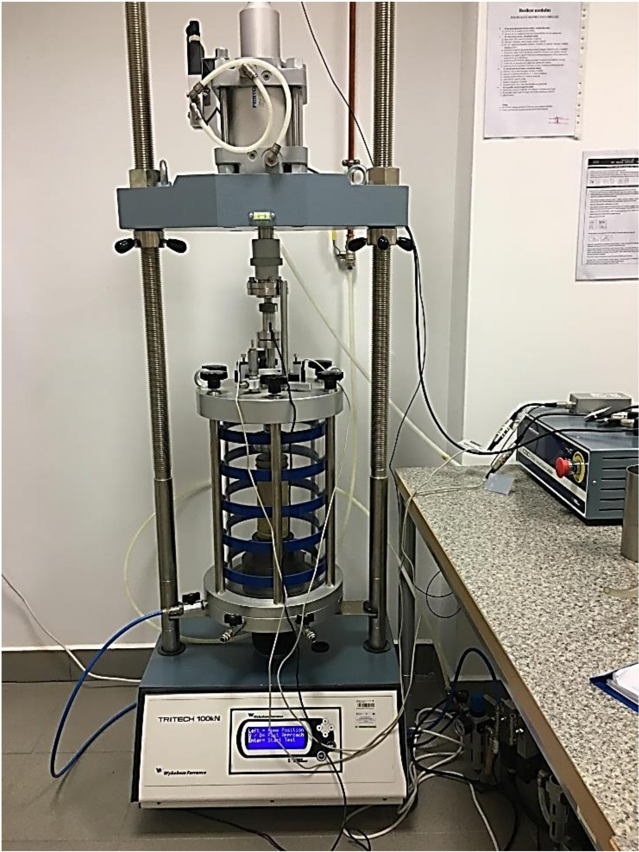
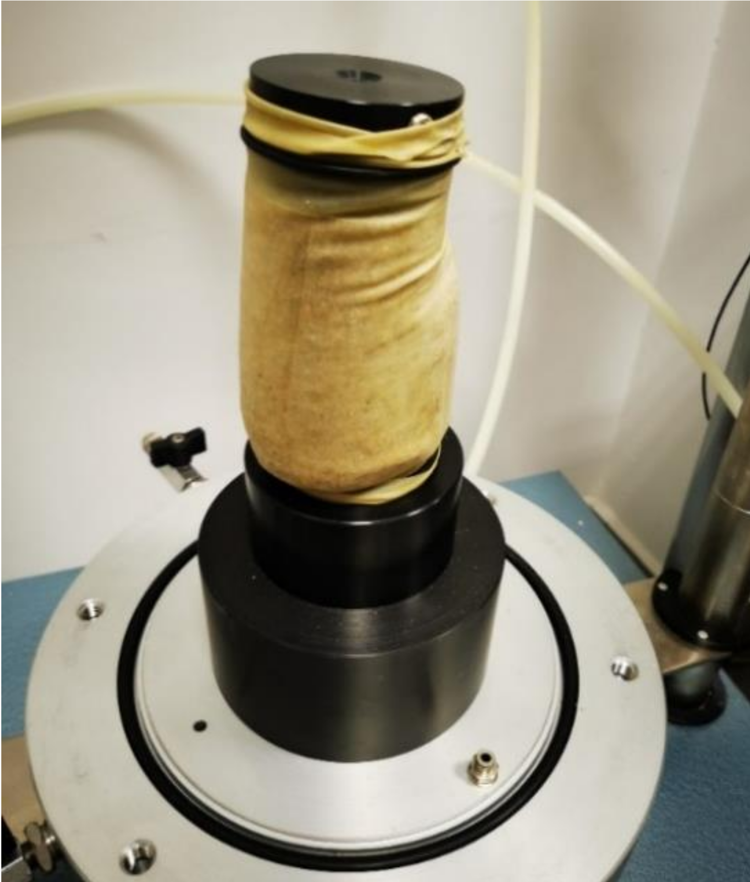
2.2. Methods
3. Results and Discussion
4. Conclusions
- (1)
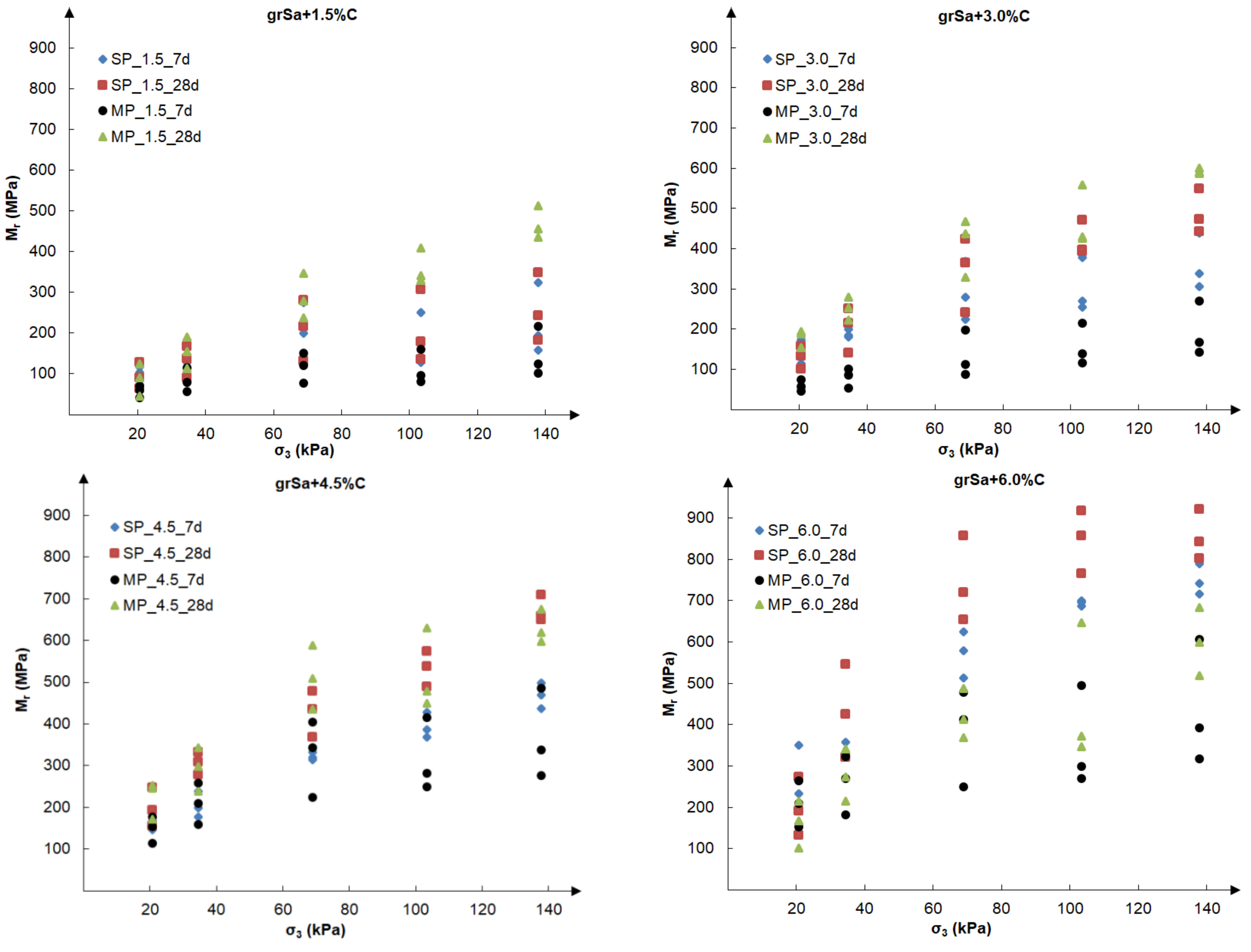
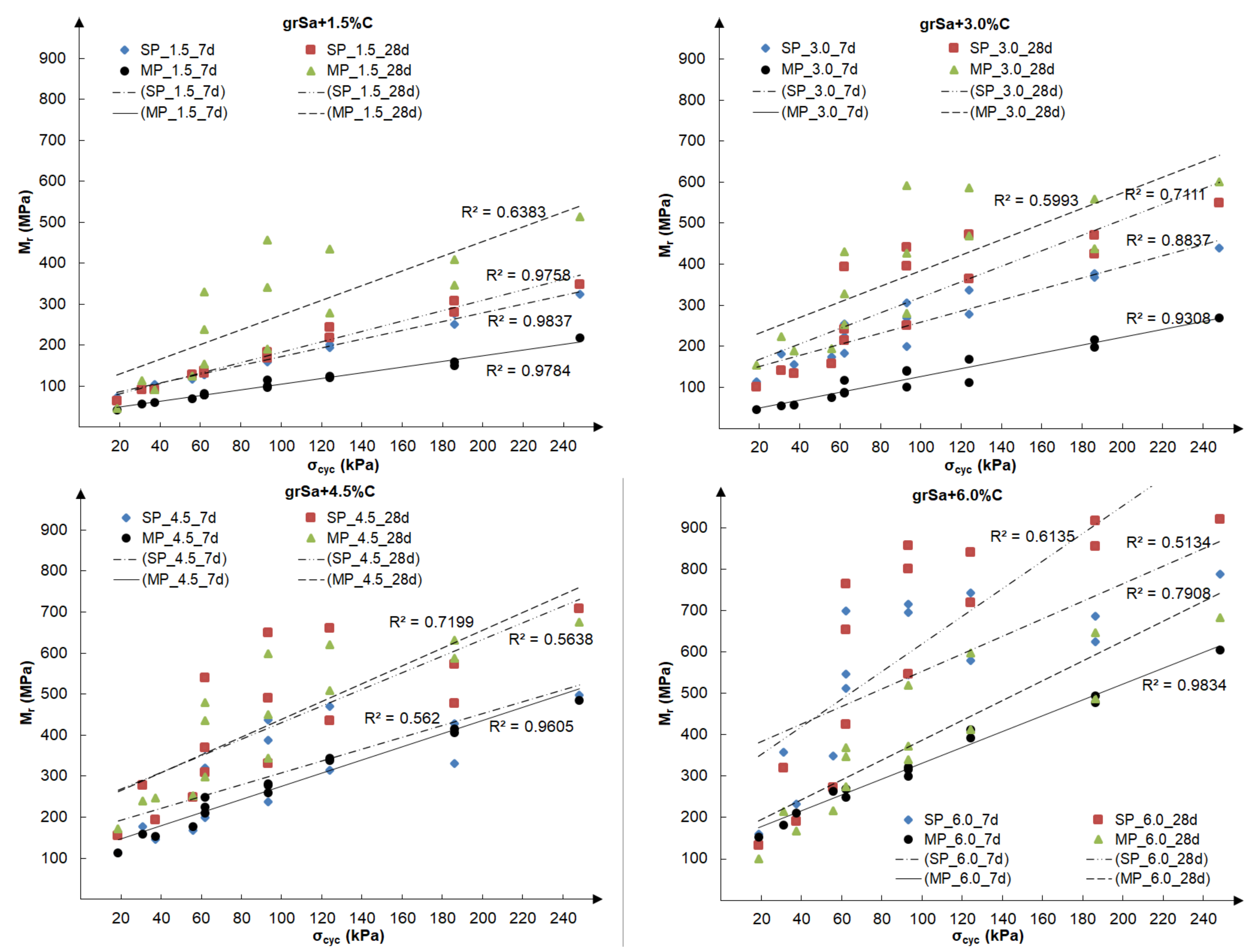
- The results of research on the resilient modulus of gravelly sand stabilised with cement indicated the possibility of using it as a material for road engineering applications. The tested soil, compacted to obtain optimum compaction parameters, can meet the AASHTO requirements [5] formulated for granular foundations as 207 MPa for both flexible and rigid road pavement structures, especially in the case of greater cement addition.
- (2)
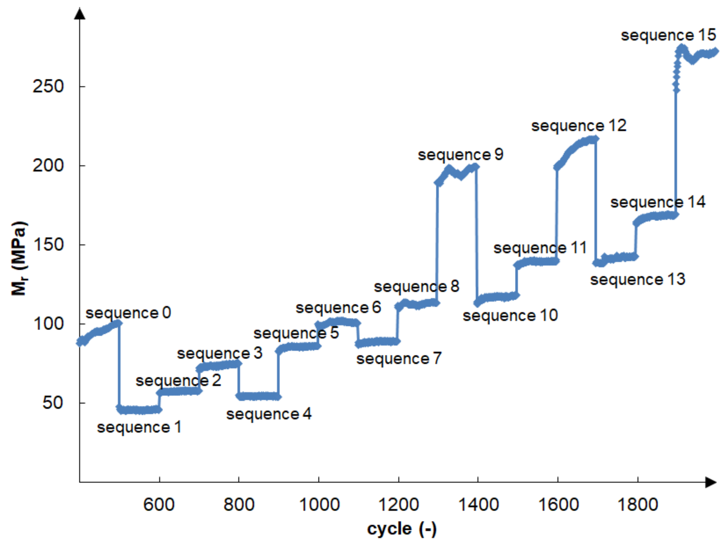
- Tested non-stabilised gravelly sand as a poorly graded material does not meet the above requirements. The tested samples compacted at the optimum water content to the maximum dry density were sheared during cyclic tests during load sequence 1 regardless of the standard Proctor or the modified Proctor compaction method.
- (3)
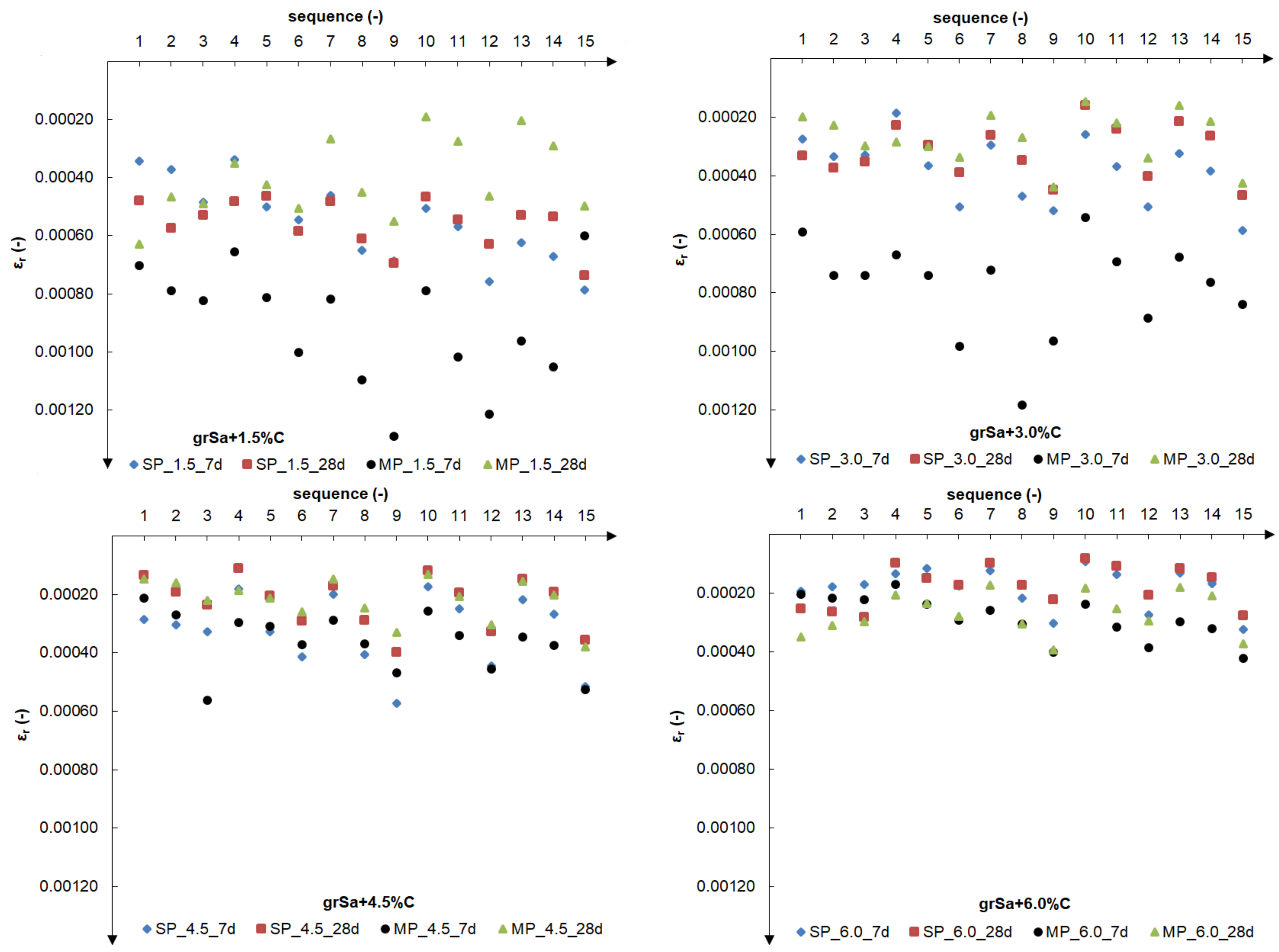
- Cement addition significantly increases the obtained values of the resilient modulus and reduces the relative resilient axial strain. Extending the curing time of the sample from 7 to 28 days also affects the value of the resilient modulus, increasing it. Another increase in the addition of 1.5% of cement reduces the value of the relative axial deformation even by several dozen percentage points, which is the main explanation of the increase in the value of the resilient modulus.
- (4)
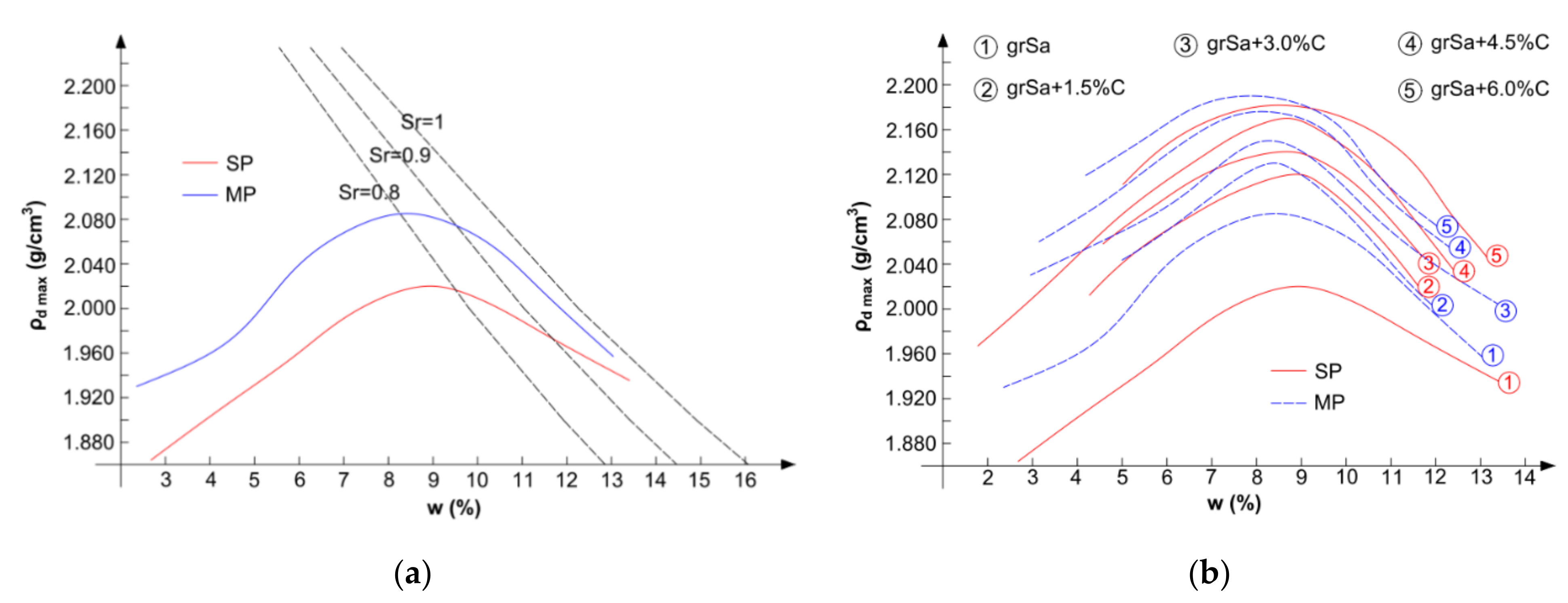
- In the case of the tested gravelly sand, increasing the compaction energy from standard to modified does not, in principle, increase the resilient modulus value, which is caused by the specific compaction characteristics of stabilised soil. For samples stabilised with the same cement additive, the compaction curves correspond to each other. The void ratios obtained at optimum water content are similar.
- (5)
- Test conditions, the confining pressure and the maximum applied axial stress affect the obtained resilient modulus values, which was also indicated in previous publications. The resilient modulus increases with an increase in confining pressure and applied axial stress 3.9–11.2 times (average 5.4 times) for various cement additives, compaction methods and sample curing times.
Author Contributions
Funding
Institutional Review Board Statement
Informed Consent Statement
Data Availability Statement
Acknowledgments
Conflicts of Interest
References
- Brown, S.F. Soil mechanics in pavement engineering. Gėotechnique 1996, 46, 383–426. [Google Scholar] [CrossRef]
- Hveem, F.N. Pavement deflections and fatigue failures. Highw. Res. Board Bull. 1955, 114, 43–87. [Google Scholar]
- Seed, H.B.; Chan, C.K.; Lee, C.E. Resilience characteristics of subgrade soils and their relation to fatigue failures in asphalt pavements. In Proceedings of the 1st International Conference on the Structural Design of Asphalt Pavements, Ann Arbor, MI, USA, 20–24 August 1962. [Google Scholar]
- Seed, H.B.; Mitry, G.; Monismith, C.L.; Chan, C.K. Factors influencing the resilient deformations of untreated aggregate base in two-layer pavements subjected to repeated loading. Highw. Res. Rec. 1967, 190, 19–57. [Google Scholar]
- AASHTO. Guide for Design of Pavement Structures; American Association of State Highway and Transportation Officials: Washington, DC, USA, 1986. [Google Scholar]
- AASHTO T 307-99. Standard Method of Test for Determining the Resilient Modulus of Soils and Aggregate Materials; American Association of State and Highway Transportation Officials: Washington, DC, USA, 2021. [Google Scholar]
- Lekarp, F.; Isacsson, U.; Dawson, A. State of the art I: Resilient response of unbound aggregates. J. Transp. Eng. 2000, 126, 66–75. [Google Scholar] [CrossRef]
- Lekarp, F.; Isacsson, U.; Dawson, A. State of the art. II: Permanent strain response of unbound aggregates. J. Transp. Eng. 2000, 126, 76–83. [Google Scholar] [CrossRef]
- Hicks, R.G.; Monismith, C.L. Factors influencing the resilient response of granular materials. High. Res. Rec. 1971, 345, 15–31. [Google Scholar]
- Rada, C.; Witczak, W.M. Comprehensive evaluation of laboratory resilient moduli results for granular material. Transp. Res. Rec. 1981, 810, 23–33. [Google Scholar]
- Ng, C.W.W.; Zhou, C.; Yuan, Q.; Xu, J. Resilient modulus of unsaturated subgrade soil: Experimental and theoretical investigations. Can. Geotechnol. J. 2013, 50, 223–232. [Google Scholar] [CrossRef]
- Samb, F.; Fall, M.; Berthaud, Y.; Bâ, M. Resilient modulus of compacted lateritic soils from Senegal at OPM conditions. Geomaterials 2013, 3, 165–171. [Google Scholar] [CrossRef]
- Tang, L.; Yan, M.H.; Ling, X.Z.; Tian, S. Dynamic behaviours of railway’s base course materials subjected to long-term low-level cyclic loading: Experimental study and empirical model. Géotechnique 2017, 67, 537–545. [Google Scholar] [CrossRef]
- Tanimoto, K.; Nishi, M. On resilient characteristics of some soils under repeated loading. Soil. Found. 1970, 2053, 75–92. [Google Scholar] [CrossRef][Green Version]
- Kim, D.; Kim, J.R. Resilient behavior of compacted subgrade soils under the repeated triaxial test. Constr. Build. Mat. 2007, 21, 1470–1479. [Google Scholar] [CrossRef]
- Sas, W.; Głuchowski, A.; Gabryś, K.; Soból, E.; Szymański, A. Long-term cyclic loading impact on the creep deformation mechanism in cohesive materials. Appl. Sci. 2017, 7, 370. [Google Scholar] [CrossRef]
- Jastrzębska, M.; Tokarz, K. Strength characteristics of clay–rubber waste mixtures in low-frequency cyclic triaxial tests. Minerals 2021, 11, 315. [Google Scholar] [CrossRef]
- Thakur, P.K.; Vinod, J.S.; Indraratna, B. Effect of confining pressure and frequency on the deformation of balast. Géotechnique 2013, 63, 786–790. [Google Scholar] [CrossRef]
- Robnett, Q.L.; Thompson, M.R. Effect of lime treatment on the resilient behavior of fine-grained soils. Transp. Res. Rec. 1976, 560, 11–20. [Google Scholar]
- Zhang, J.; Peng, J.; Liu, W.; Lu, W. Predicting resilient modulus of fine-grained subgrade soils considering relative compaction and matric suction. Road Mater. Pavement Des. 2019, 22, 702–715. [Google Scholar] [CrossRef]
- Camargo, F.; Benson, C.; Edil, T. An assessment of resilient modulus testing: Internal and external deflection measurements. Geotechnol. Test. J. 2012, 35, 20120077. [Google Scholar] [CrossRef]
- Bhuvaneshwari, S.; Robinson, R.G.; Gandhi, S.R. Resilient modulus of lime treated expansive soil. Geotechnol. Geol. Eng. 2019, 37, 305–315. [Google Scholar] [CrossRef]
- Thompson, M.R. Lime reactivity of Illinois soils. J. Soil Mech. Found. Div. 1966, 92, 67–92. [Google Scholar] [CrossRef]
- Yuan, H.; Li, W.; Wang, Y.; Lin, H.; Liu, Y. Resilient modulus—Physical parameters relationship of improved red clay by dynamic tri-axial test. Appl. Sci. 2019, 9, 1155. [Google Scholar] [CrossRef]
- Ismail, A.; Baghini, M.S.; Karim, M.R.B.; Shokri, F.; Al-Mansob, R.A.; Firoozi, A.A.; Firoozi, A.A. Laboratory investigation on the strength characteristics of cement-treated base. Appl. Mech. Mater. 2014, 507, 353–360. [Google Scholar] [CrossRef]
- Hanifa, K.; Abu-Farsakh, M.Y.; Gautreau, G.P. Design Values of Resilient Modulus for Stabilized and Non-Stabilized Base; Report No. FHWA/LA.14/521; Louisiana Department of Transportation and Development: Baton Rouge, LA, USA, 2015. [Google Scholar]
- Saxena, P.; Tompkins, D.; Khazanovich, L.; Balbo, J.T. Evaluation of characterization and performance modeling of cementitiously stabilized layers in the Mechanistic–Empirical Pavement Design Guide. Transp. Res. Rec. 2010, 2186, 111–119. [Google Scholar] [CrossRef]
- Carpenter, S.H.; Crovetti, M.R.; Smith, K.L.; Rmeili, E.; Wilson, T. Pavement Design and Construction Consideration. In Soil and Base Stabilization and Associated Drainage Consideration; Publication No. FHWA-SA-93-004; U.S. Department of Transportation: Washington, DC, USA, 1992; Volume I. [Google Scholar]
- AASHTO. Standard Recommended Practice for Stabilization of Subgrade Soils and Base Materials; American Association of State Highway and Transportation Officials: Washington, DC, USA, 2008. [Google Scholar]
- Hydraulically Bound Mixtures—Specifications—Part 15: Hydraulically Stabilized Soils Does Not Limit Any Soil Grading to Cement Stabilization; EN 14227-15:2015; European Committee for Standardization: Brussels, Belgium, 2015.
- Tests for Geometrical Properties of Aggregates—Part 1: Determination of Particle Size Distribution—Sieving Method; EN 933-1:2012; European Committee for Standardization: Brussels, Belgium, 2012.
- Geotechnical Investigation and Testing. Identification and Classification of Soil. Identification and Description; EN ISO 14688-1:2018; ISO: Geneva, Switzerland, 2018. [Google Scholar]
- Geotechnical Investigation and Testing—Identification and Classification of Soil—Part 2: Principles for a Classification; EN ISO 14688-2:2018-05; ISO: Geneva, Switzerland, 2018.
- Aggregates for Unbound and Hydraulically Bounded Materials for Use in Civil Engineering Work and Road Construction; EN 13242: 2007; European Committee for Standardization: Brussels, Belgium, 2007.
- Standard Specification for Materials for Soil-Aggregate Subbase, Base, and Surface Courses; ASTM D1241-15; ASTM International: West Conshohocken, PA, USA, 2020.
- Patakiewicz, M.A.; Zabielska-Adamska, K. Crushing of non-cohesive soil grains under dynamic loading. Procedia Eng. 2017, 189, 80–85. [Google Scholar] [CrossRef]
- Unbound and Hydraulically Bound Mixtures—Part 2: Test Methods for Laboratory Reference Density and Water Content—Proctor Compaction; EN 13286-2:2010; European Committee for Standardization: Brussels, Belgium, 2010.
- Zabielska-Adamska, K. Laboratory compaction of fly ash and fly ash with cement additions. J. Hazard. Mater. 2008, 151, 481–489. [Google Scholar] [CrossRef]
- Shooshpasha, I.; Shirvani, R.A. Effect of cement stabilization on geotechnical properties of sandy soils. Geomech. Eng. 2015, 8, 17–31. [Google Scholar] [CrossRef]
- Werkmeister, S. Permanent Deformation Behavior of Unbound Granular Materials. Doctoral thesis, University of Technology, Dresden, Germany, 2003. [Google Scholar]
- Erlingsson, S.; Rahman, S.; Salour, F. Characteristic of unbound granular materials and subgrades based on multi stage RLT testing. Transp. Geotechnol. 2017, 13, 28–42. [Google Scholar] [CrossRef]
- Ramos, A.; Correia, A.G.; Indraratna, B.; Ngo, T.; Calçada, R.; Costa, P.A. Mechanistic-empirical permanent deformation models: Laboratory testing, modelling and ranking. Transp. Geotechnol. 2020, 23, 100326. [Google Scholar] [CrossRef]


| Material | Compaction Method | ρs (g/cm3) | |||||
|---|---|---|---|---|---|---|---|
| Standard Proctor | Modified Proctor | ||||||
| wopt (%) | ρd max (g/cm3) | e (–) | wopt (%) | ρd max (g/cm3) | e (–) | ||
| grSa | 9.00 | 2.020 | 0.31 | 8.50 | 2.085 | 0.27 | 2.65 |
| grSa + 1.5%C | 8.90 | 2.120 | 0.25 | 8.40 | 2.130 | 0.25 | 2.66 |
| grSa + 3.0%C | 8.80 | 2.140 | 0.24 | 8.30 | 2.150 | 0.24 | 2.66 |
| grSa + 4.5%C | 8.70 | 2.170 | 0.23 | 8.10 | 2.176 | 0.23 | 2.67 |
| grSa + 6.0%C | 8.50 | 2.182 | 0.23 | 7.90 | 2.190 | 0.22 | 2.68 |
| Sequence Number | Confining Pressure (kPa) | Max. Applied Axial Stress (kPa) | Cyclic Stress σcyclic (kPa) | Number of Load Applications |
|---|---|---|---|---|
| 0 | 103.4 | 103.4 | 93.1 | 500–1000 |
| 1 | 20.7 | 20.7 | 18.6 | 100 |
| 2 | 20.7 | 41.4 | 37.3 | 100 |
| 3 | 20.7 | 62.1 | 55.9 | 100 |
| 4 | 34.5 | 34.5 | 31.0 | 100 |
| 5 | 34.5 | 68.9 | 62.0 | 100 |
| 6 | 34.5 | 103.4 | 93.1 | 100 |
| 7 | 68.9 | 68.9 | 62.0 | 100 |
| 8 | 68.9 | 137.9 | 124.1 | 100 |
| 9 | 68.9 | 206.8 | 186.1 | 100 |
| 10 | 103.4 | 68.9 | 62.0 | 100 |
| 11 | 103.4 | 103.4 | 93.1 | 100 |
| 12 | 103.4 | 206.8 | 186.1 | 100 |
| 13 | 137.9 | 103.4 | 93.1 | 100 |
| 14 | 137.9 | 137.9 | 124.1 | 100 |
| 15 | 137.9 | 275.8 | 248.2 | 100 |
Publisher’s Note: MDPI stays neutral with regard to jurisdictional claims in published maps and institutional affiliations. |
© 2021 by the authors. Licensee MDPI, Basel, Switzerland. This article is an open access article distributed under the terms and conditions of the Creative Commons Attribution (CC BY) license (https://creativecommons.org/licenses/by/4.0/).
Share and Cite
Zabielska-Adamska, K.; Wasil, M.; Dobrzycki, P. Resilient Response of Cement-Treated Coarse Post-Glacial Soil to Cyclic Load. Materials 2021, 14, 6495. https://doi.org/10.3390/ma14216495
Zabielska-Adamska K, Wasil M, Dobrzycki P. Resilient Response of Cement-Treated Coarse Post-Glacial Soil to Cyclic Load. Materials. 2021; 14(21):6495. https://doi.org/10.3390/ma14216495
Chicago/Turabian StyleZabielska-Adamska, Katarzyna, Mariola Wasil, and Patryk Dobrzycki. 2021. "Resilient Response of Cement-Treated Coarse Post-Glacial Soil to Cyclic Load" Materials 14, no. 21: 6495. https://doi.org/10.3390/ma14216495
APA StyleZabielska-Adamska, K., Wasil, M., & Dobrzycki, P. (2021). Resilient Response of Cement-Treated Coarse Post-Glacial Soil to Cyclic Load. Materials, 14(21), 6495. https://doi.org/10.3390/ma14216495