
In Situ CT Tensile Testing of an Additively Manufactured and Heat-Treated Metastable ß-Titanium Alloy (Ti-5Al-5Mo-5V-3Cr)

 , ,
, ,
Abstract
:1. Introduction
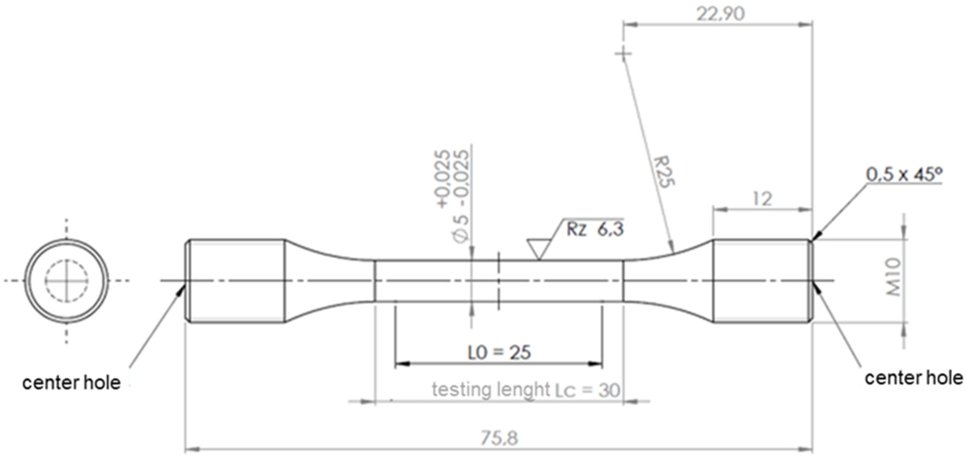
2. Materials and Methods
2.1. Ti-5553
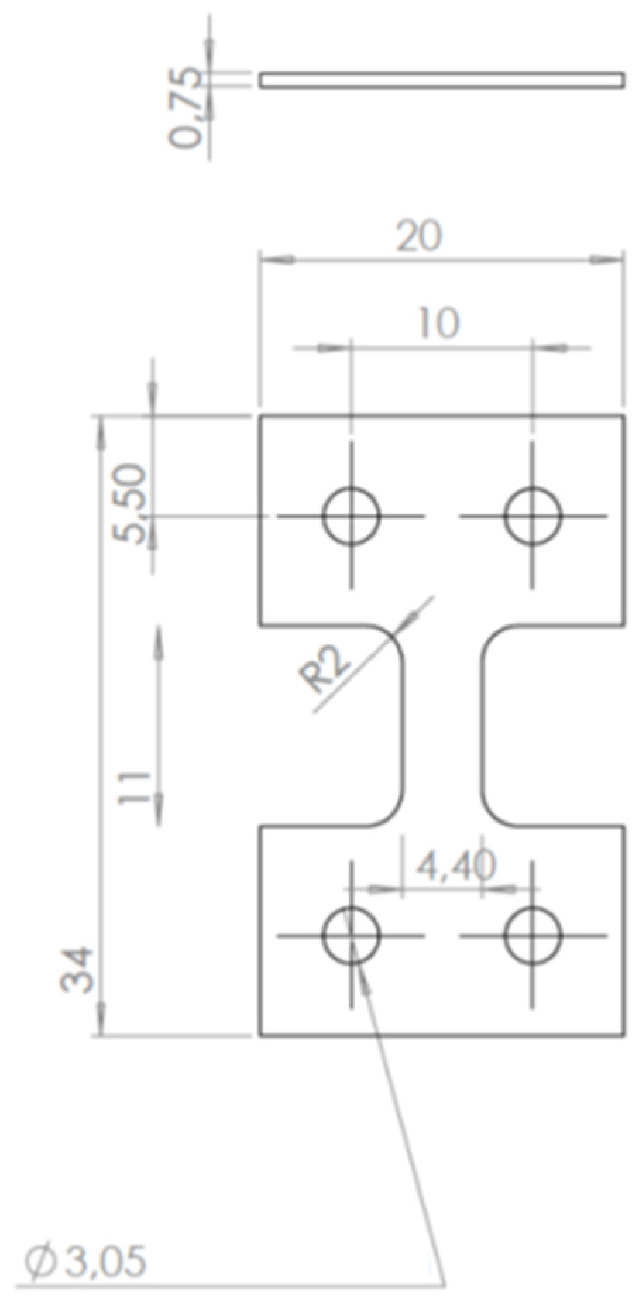
2.2. EB-PBF
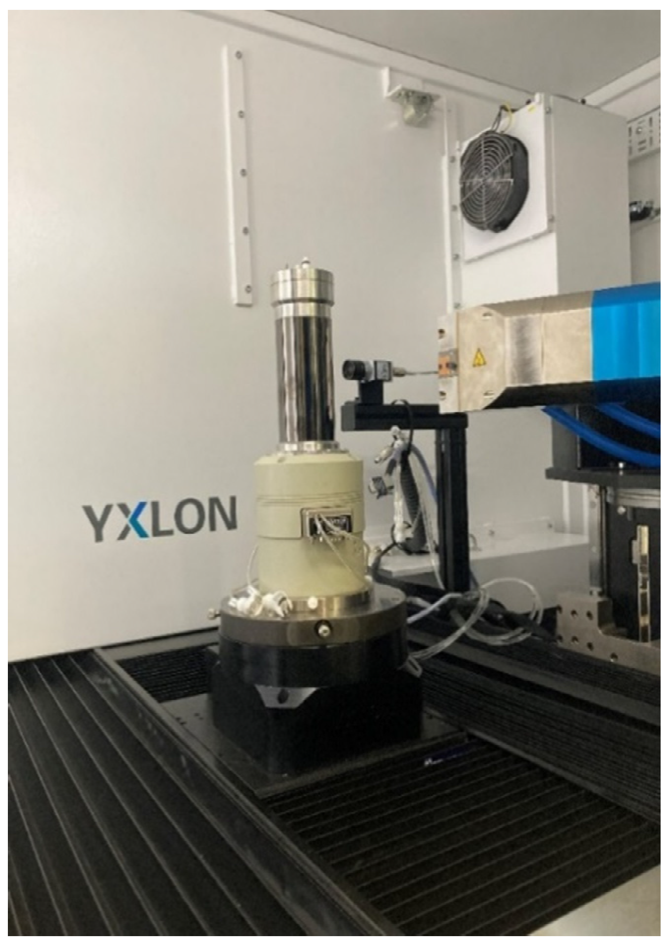
2.3. Industrial Computer Tomography
3. Results
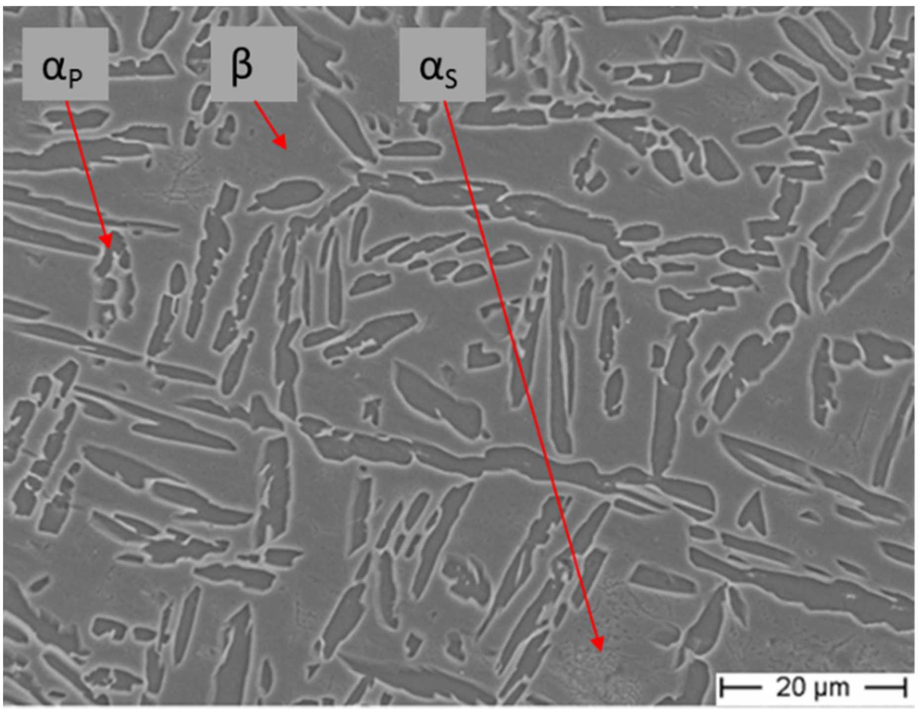
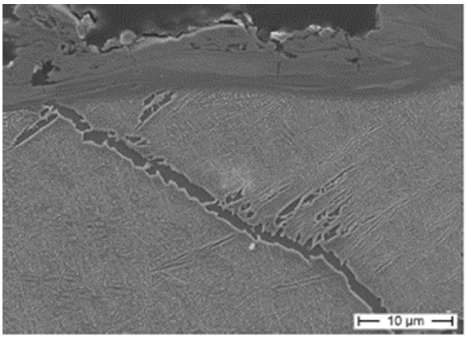
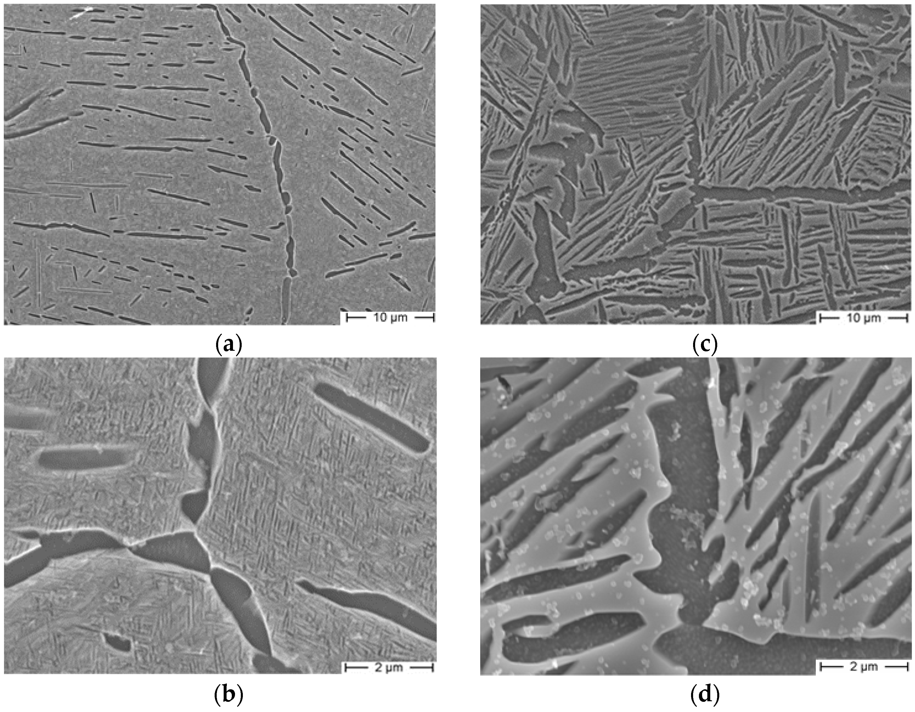
3.1. Microstructure
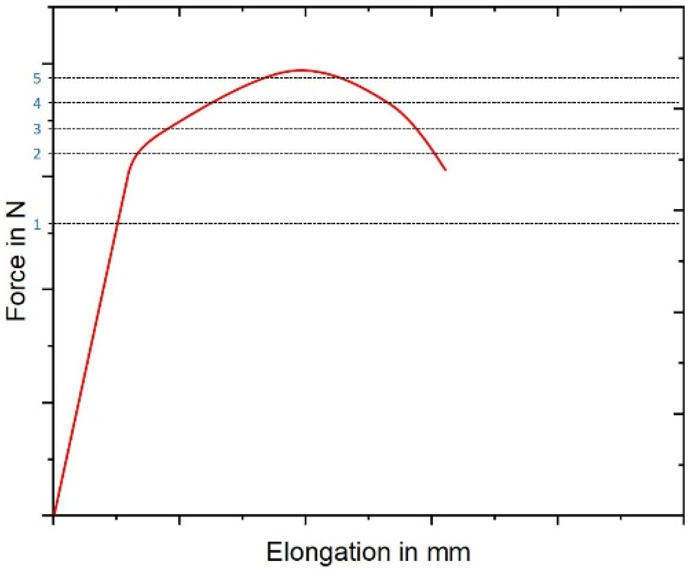
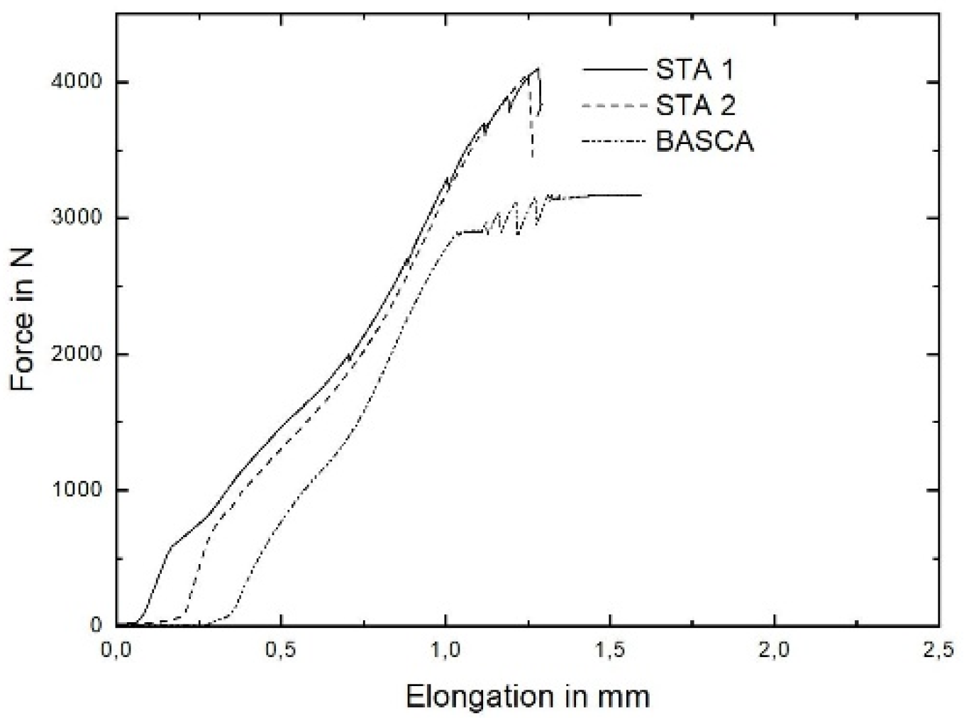
3.2. Mechanical Properties
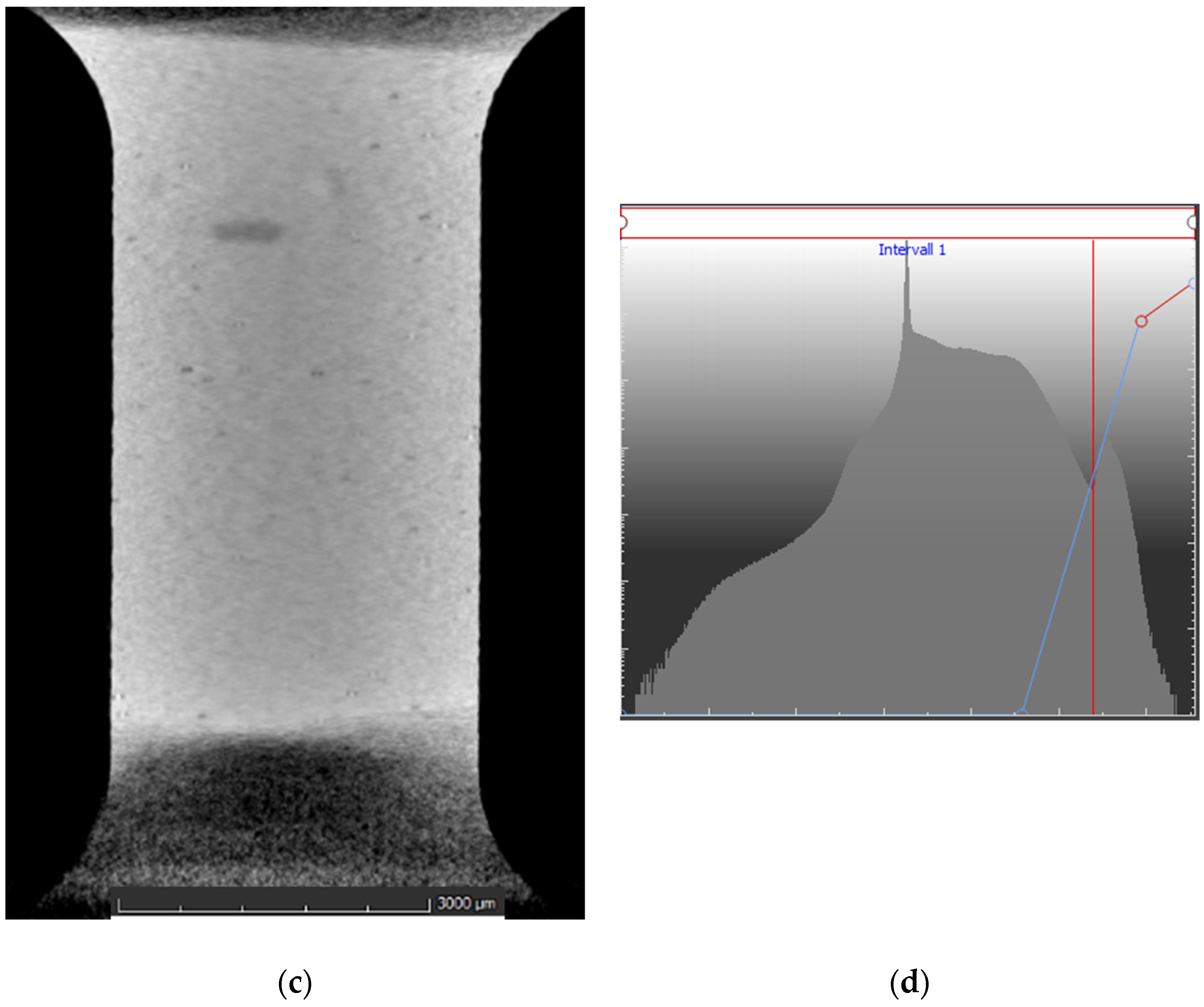
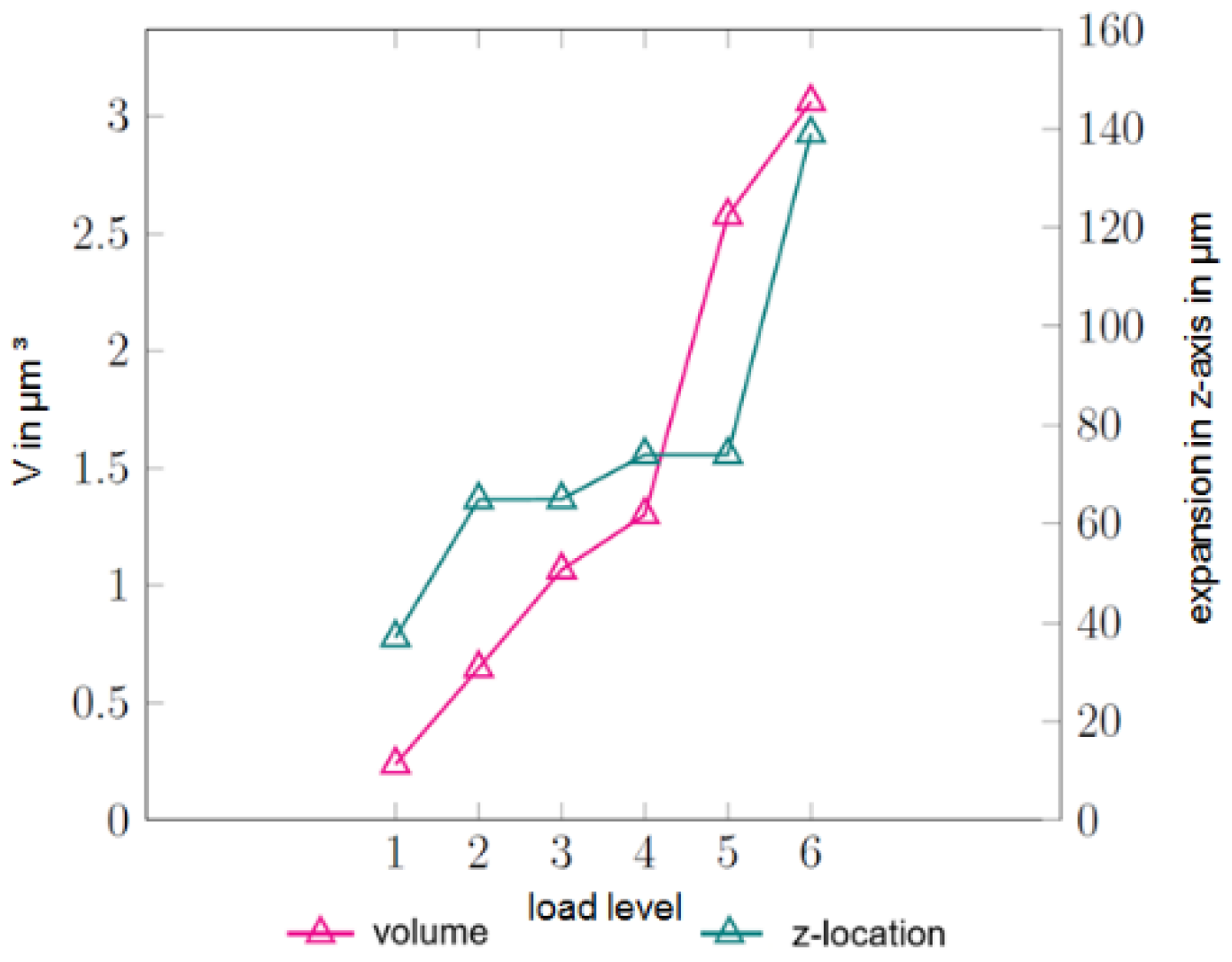
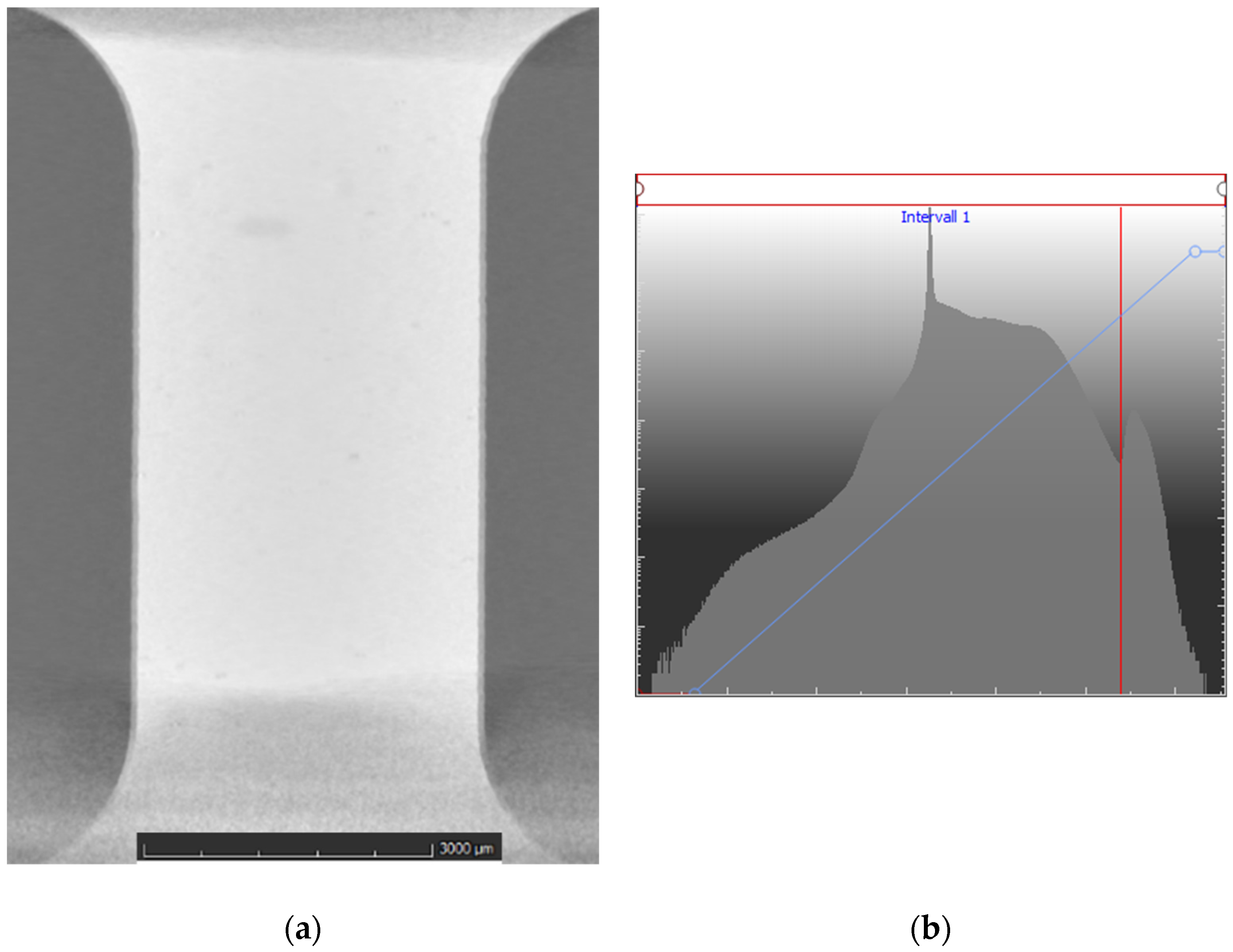
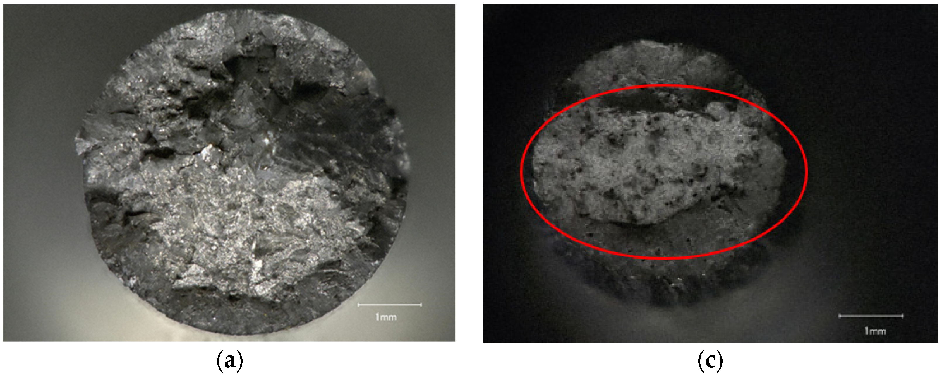
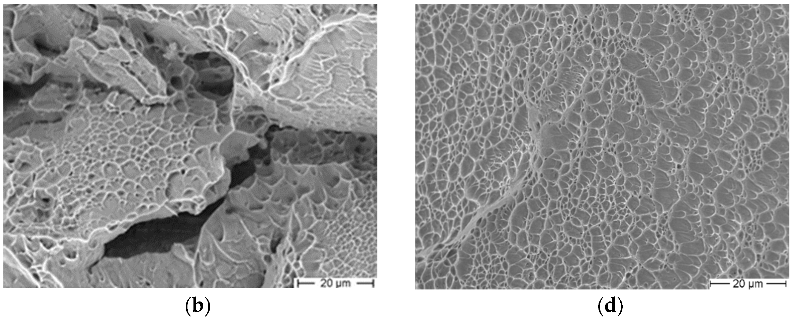
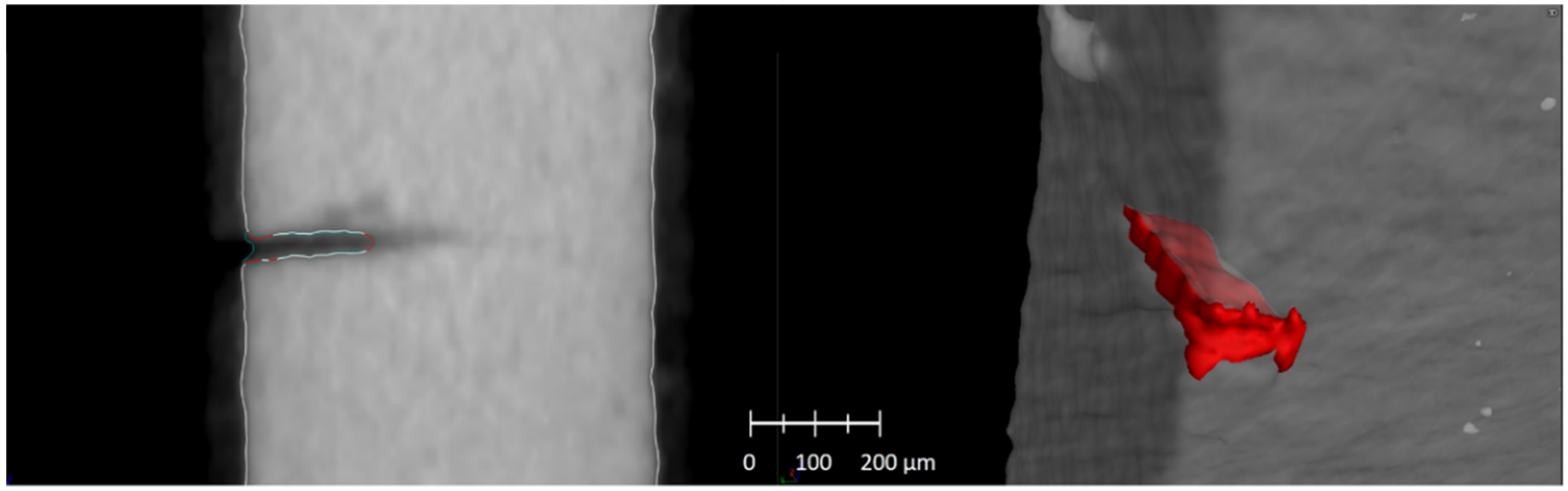
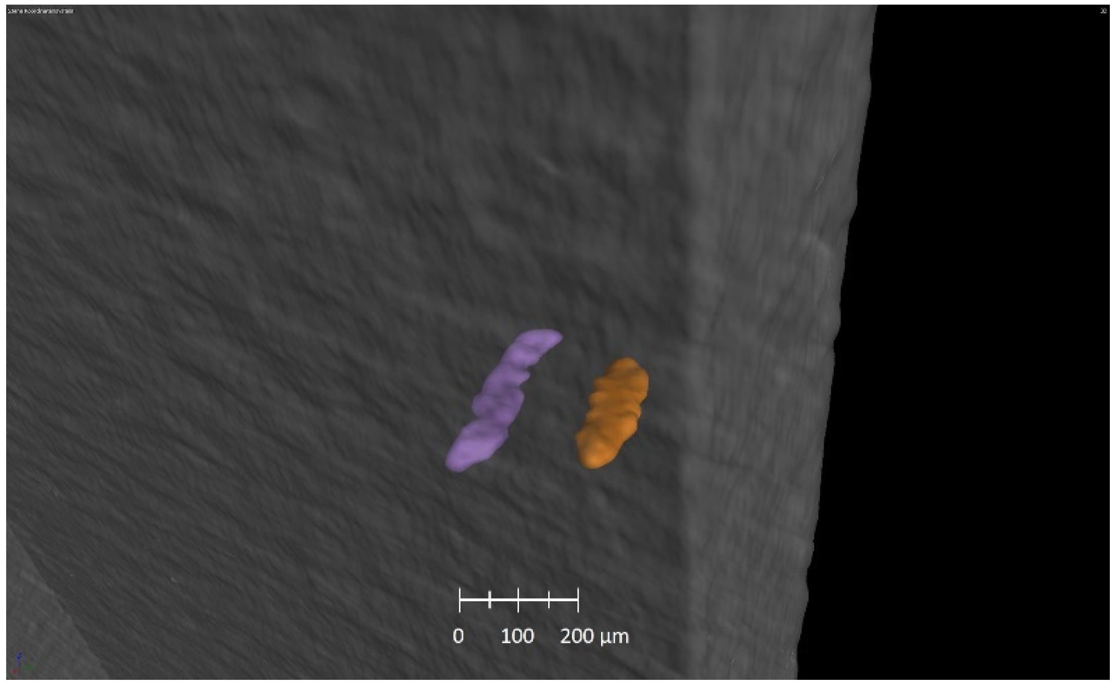
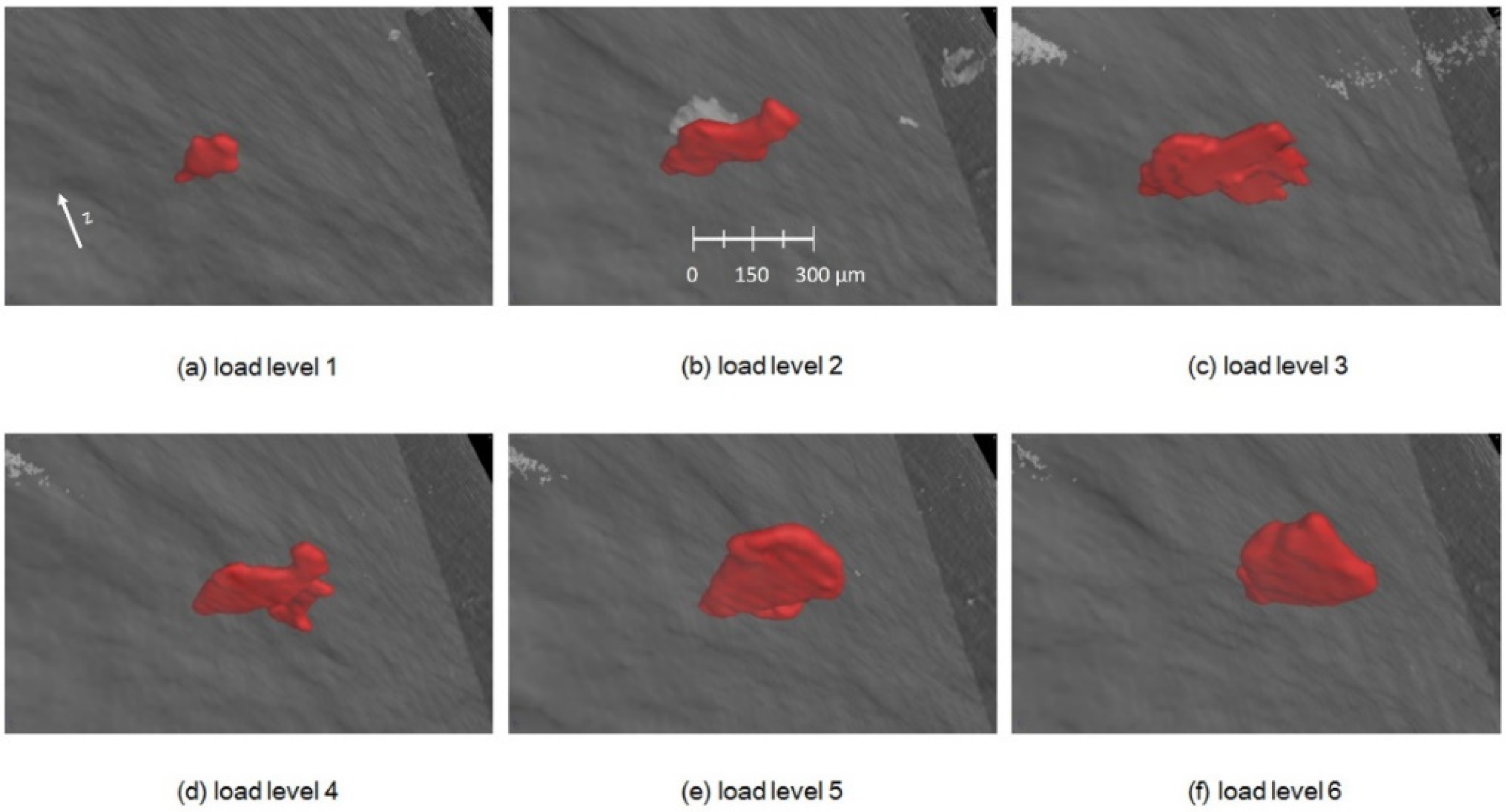
3.3. Industrial Computer Tomography
4. Discussion
4.1. Microstructure–Mechanical Properties Correlation
4.2. In Situ Tensile Testing
5. Conclusions
Author Contributions
Funding
Conflicts of Interest
References
- Wilke, S. ‘Umweltbewusstsein und Umweltverhalten’, Umweltbundesamt. 4 July 2013. Available online: https://www.umweltbundesamt.de/daten/private-haushalte-konsum/umweltbewusstsein-umweltverhalten (accessed on 19 August 2021).
- Willner, R.; Lender, S.; Ihl, A.; Wilsnack, C.; Gruber, S.; Brandão, A.; Pambaguian, L.; Riede, M.; López, E.; Brueckner, F.; et al. Potential and challenges of additive manufacturing for topology optimized spacecraft structures. J. Laser Appl. 2020, 32, 032012. [Google Scholar] [CrossRef]
- Ramadani, R.; Belsak, A.; Kegl, M.; Predan, J.; Pehan, S. Topology Optimization Based Design of Lightweight and Low Vibration Gear Bodies. Int. J. Simul. Model. 2018, 17, 92–104. [Google Scholar] [CrossRef]
- Seabra, M.; Azevedo, J.; Araújo, A.; Reis, L.; Pinto, E.; Alves, N.; Santos, R.; Mortágua, J.P. Selective laser melting (SLM) and topology optimization for lighter aerospace componentes. Procedia Struct. Integr. 2016, 1, 289–296. [Google Scholar] [CrossRef] [Green Version]
- Emmelmann, C.; Petersen, M.; Kranz, J.; Wycisk, E. Bionic Lightweight Design by Laser Additive Manufacturing (LAM) for Aircraft Industry; SPIE Eco-Photonics: Strasbourg, France, 2011; p. 80650L. [Google Scholar] [CrossRef] [Green Version]
- Khajavi, S.H.; Partanen, J.; Holmström, J. Additive manufacturing in the spare parts supply chain. Comput. Ind. 2014, 65, 50–63. [Google Scholar] [CrossRef]
- Herzog, D.; Seyda, V.; Wycisk, E.; Emmelmann, C. Additive manufacturing of metals. Acta Mater. 2016, 117, 371–392. [Google Scholar] [CrossRef]
- Uriondo, A.; Esperon-Miguez, M.; Perinpanayagam, S. The present and future of additive manufacturing in the aerospace sector: A review of important aspects. Proc. Inst. Mech. Eng. Part G J. Aerosp. Eng. 2015, 229, 2132–2147. [Google Scholar] [CrossRef]
- DebRoy, T.; Wei, H.; Zuback, J.; Mukherjee, T.; Elmer, J.; Milewski, J.; Beese, A.; Wilson-Heid, A.; De, A.; Zhang, W. Additive manufacturing of metallic components—Process, structure and properties. Prog. Mater. Sci. 2018, 92, 112–224. [Google Scholar] [CrossRef]
- Antunes, R.A.; Salvador, C.A.F.; De Oliveira, M.C.L. Materials Selection of Optimized Titanium Alloys for Aircraft Applications. Mater. Res. 2018, 21. [Google Scholar] [CrossRef] [Green Version]
- Panza-Giosa, R. Mechanical Properties of Heat treated Ti-5Al-5V-5Mo-3Cr—An Attempt to Define Critical Properties of Various Microstructural Features. In Proceedings of the ITA Titanium Conference, Las Vegas, NV, USA, 8 April 2008; p. 35. [Google Scholar]
- Nyakana, S.L.; Fanning, J.C.; Boyer, R.R. ‘Quick Reference Guide for _ Titanium Alloys in the 00s’. J. Mater. Eng. Perform. 2005, 14, 799–811. [Google Scholar] [CrossRef]
- Leyens, C.; Peters, M. (Eds.) Titanium and Titanium Alloys: Fundamentals and Applications; Wiley-VCH Verlag GmbH & Co. KGaA: Weinheim, Germany, 2003. [Google Scholar] [CrossRef]
- Lütjering, G.; Williams, J.C. Titanium, 2rd ed.; Springer: Berlin/Heidelberg, Germany, 2007. [Google Scholar]
- Sadeghpour, S.; Abbasi, S.; Morakabati, M.; Bruschi, S. Correlation between alpha phase morphology and tensile properties of a new beta titanium alloy. Mater. Des. 2017, 121, 24–35. [Google Scholar] [CrossRef]
- Azizi, H.; Zurob, H.; Bose, B.; Ghiaasiaan, S.R.; Wang, X.; Coulson, S.; Duz, V.; Phillion, A. Additive manufacturing of a novel Ti-Al-V-Fe alloy using selective laser melting. Addit. Manuf. 2018, 21, 529–535. [Google Scholar] [CrossRef] [Green Version]
- Zheng, Y.; Williams, R.E.; Sosa, J.M.; Wang, Y.; Banerjee, R.; Fraser, H.L. The role of the ω phase on the non-classical precipitation of the α phase in metastable β-titanium alloys. Scr. Mater. 2016, 111, 81–84. [Google Scholar] [CrossRef]
- Rodrigues, M.C.; Garcin, T.; Militzer, M. In-situ measurement of α formation kinetics in a metastable β Ti-5553 alloy using laser ultrasonics. J. Alloy. Compd. 2021, 866, 158954. [Google Scholar] [CrossRef]
- Nag, S.; Banerjee, R.; Srinivasan, R.; Hwang, J.; Harper, M.; Fraser, H. ω-Assisted nucleation and growth of α precipitates in the Ti–5Al–5Mo–5V–3Cr–0.5Fe β titanium alloy. Acta Mater. 2009, 57, 2136–2147. [Google Scholar] [CrossRef]
- Hendl, J. Gefüge-Eigenschaftsbeziehung einer Ti-5Al-5Mo-5V-3Cr Legierung Hergestellt Mittels Selektiven Elektronenstrahlschmelzen; Technische Universität Dresden: Dresden, Germany, 2018. [Google Scholar]
- Huang, C.; Zhao, Y.; Xin, S.; Zhou, W.; Li, Q.; Zeng, W. Effect of microstructure on tensile properties of Ti–5Al–5Mo–5V–3Cr–1Zr alloy. J. Alloy. Compd. 2017, 693, 582–591. [Google Scholar] [CrossRef]
- Li, C.-L.; Mi, X.-J.; Ye, W.-J.; Hui, S.-X.; Yu, Y.; Wang, W.-Q. Effect of solution temperature on microstructures and tensile properties of high strength Ti–6Cr–5Mo–5V–4Al alloy. Mater. Sci. Eng. A 2013, 578, 103–109. [Google Scholar] [CrossRef]
- Yadollahi, A.; Shamsaei, N. Additive manufacturing of fatigue resistant materials: Challenges and opportunities. Int. J. Fatigue 2017, 98, 14–31. [Google Scholar] [CrossRef] [Green Version]
- Sun, Y.; Huang, B.; Puleo, D.; Jawahir, I. Enhanced Machinability of Ti-5553 Alloy from Cryogenic Machining: Comparison with MQL and Flood-cooled Machining and Modeling. Procedia CIRP 2015, 31, 477–482. [Google Scholar] [CrossRef] [Green Version]
- GKN Powder Materials. 2019. Available online: https://www.gknpm.com/globalassets/downloads/additive-manufacturing/datasheets-am-materials/datasheets---titanium-alloys/ancoram-ti-5553.pdf/ (accessed on 23 August 2021).
- TAG. Available online: https://www.tag.it/de/titanlegierungen-die-klassifizierung-teil-2/5/ (accessed on 23 December 2019).
- Zopp, C.; Blümer, S.; Schubert, F.; Kroll, L. Processing of a metastable titanium alloy (Ti-5553) by selective laser melting. Ain Shams Eng. J. 2017, 8, 475–479. [Google Scholar] [CrossRef] [Green Version]
- Schatt, W.; Blumenauer, H. (Eds.) Werkstoffwissenschaft, 8th ed.; Dt. Verl. für Grundstoffindustrie: Stuttgart, Germany, 1996. [Google Scholar]
- Jones, N.; Dashwood, R.; Jackson, M.; Dye, D. β Phase decomposition in Ti–5Al–5Mo–5V–3Cr. Acta Mater. 2009, 57, 3830–3839. [Google Scholar] [CrossRef]
- Shekhar, S.; Sarkar, R.; Kar, S.K.; Bhattacharjee, A. Effect of solution treatment and aging on microstructure and tensile properties of high strength β titanium alloy, Ti–5Al–5V–5Mo–3Cr. Mater. Des. 2014, 66, 596–610. [Google Scholar] [CrossRef]
- Kar, S.K.; Ghosh, A.; Fulzele, N.; Bhattacharjee, A. Quantitative microstructural characterization of a near beta Ti alloy, Ti-5553 under different processing conditions. Mater. Charact. 2013, 81, 37–48. [Google Scholar] [CrossRef]
- Ghosh, A.; Sivaprasad, S.; Bhattacharjee, A.; Kar, S.K. Microstructure–fracture toughness correlation in an aircraft structural component alloy Ti–5Al–5V–5Mo–3Cr. Mater. Sci. Eng. A 2013, 568, 61–67. [Google Scholar] [CrossRef]
- Baudana, G.; Biamino, S.; Klöden, B.; Kirchner, A.; Weißgärber, T.; Kieback, B.; Pavese, M.; Ugues, D.; Fino, P.; Badini, C. Electron Beam Melting of Ti-48Al-2Nb-0.7Cr-0.3Si: Feasibility investigation. Intermetallics 2016, 73, 43–49. [Google Scholar] [CrossRef]
- Fatemi, A.; Molaei, R.; Simsiriwong, J.; Sanaei, N.; Pegues, J.; Torries, B.; Phan, N.; Shamsaei, N. Fatigue behaviour of additive manufactured materials: An overview of some recent experimental studies on Ti-6Al-4V considering various processing and loading direction effects. Fatigue Fract. Eng. Mater. Struct. 2019, 42, 991–1009. [Google Scholar] [CrossRef]
- Masuo, H. Influence of defects, surface roughness and HIP on the fatigue strength of Ti-6Al-4V manufactured by additive manufacturing. Int. J. Fatigue 2018, 117, 163–179. [Google Scholar] [CrossRef]
- Carter, L.N.; Attallah, M.M.; Reed, R.C. Laser Powder Bed Fabrication of Nickel-Base Superalloys: Influence of Parameters. Superalloys 2012, 2012, 2826–2834. [Google Scholar]
- King, W.E.; Barth, H.D.; Castillo, V.M.; Gallegos, G.F.; Gibbs, J.; Hahn, D.E.; Kamath, C.; Rubenchik, A.M. Observation of keyhole-mode laser melting in laser powder-bed fusion additive manufacturing. J. Mater. Process. Technol. 2014, 214, 2915–2925. [Google Scholar] [CrossRef]
- Bauch, J.; Rosenkranz, R. Physikalische Werkstoffdiagnostik; Springer: Berlin, Germany, 2017. [Google Scholar] [CrossRef]
- DIN Deutsches Institut für Normung e. V. DIN EN ISO 6892-1; Beuth Verlag: Berlin, Germany, 2016. [Google Scholar]
- Clément, N.; Lenain, A.; Jacques, P. Mechanical property optimization via microstructural control of new metastable beta titanium alloys. JOM 2007, 59, 50–53. [Google Scholar] [CrossRef]
- Contrepois, Q.; Carton, M.; Lecomte-Beckers, J. Characterization of the β Phase Decomposition in Ti-5Al-5Mo-5V-3Cr at Slow Heating Rates. Open J. Met. 2011, 1, 1–11. [Google Scholar] [CrossRef] [Green Version]
- Dehghan-Manshadi, A.; Dippenaar, R.J. Development of α-phase morphologies during low temperature isothermal heat treatment of a Ti–5Al–5Mo–5V–3Cr alloy. Mater. Sci. Eng. A 2010, 528, 1833–1839. [Google Scholar] [CrossRef]
- Dogan, B.; Terlinde, G.; Schwalbe, K.-H. Effect of Yield Stress and Environment on Fatigue Crack Propagation of Aged ti-10v-2fe-3al. In Proceedings of the Sixth World Conference on Titanium, Cannes, France, 6–9 June 1988. [Google Scholar]
- Ammar, H.; Samuel, A.; Samuel, F. Porosity and the fatigue behavior of hypoeutectic and hypereutectic aluminum–silicon casting alloys. Int. J. Fatigue 2008, 30, 1024–1035. [Google Scholar] [CrossRef]
- Crupi, V.; Kara, E.; Epasto, G.; Guglielmino, E.; Aykul, H. Static behavior of lattice structures produced via direct metal laser sintering technology. Mater. Des. 2017, 135, 246–256. [Google Scholar] [CrossRef]
- Leuders, S.; Thöne, M.; Riemer, A.; Niendorf, T.; Tröster, T.; Richard, H.; Maier, H. On the mechanical behaviour of titanium alloy TiAl6V4 manufactured by selective laser melting: Fatigue resistance and crack growth performance. Int. J. Fatigue 2013, 48, 300–307. [Google Scholar] [CrossRef]


| Alloy | Tβ in °C | YS in MPa | UTS in MPa | Young Modulus in GPa |
|---|---|---|---|---|
| Pure titanium | 882 | 140 | 100–145 | 110 |
| Ti-6Al4V | 995 | 800–1100 | 900–1200 | 110–140 |
| Ti-10V-2Fe-3Al | 800 | 1000-1200 | 1000-1400 | 110 |
| Ti-5Mo-5V-5Al-3Cr | 845 | 1250 | 1400 | 110 |
| Material State | YS in MPa | UTS in MPa | Εlongation at Break in % |
|---|---|---|---|
| As-builtcon. | 860 ± 0 | 887 ± 71 | 21.90 ± 2.9 |
| As-builtin situ | 820 ± 3 | 856 ± 5 | 1.1 ± 0.2 |
| STAcon. | 1360 ± 14 | 1460 ± 21 | 4.2 ± 1.3 |
| STAin situ | 1166 ± 42 | 1212 ± 41 | 1.21 ± 0.1 |
| BASCAcon. | 888 ± 15 | 971 ± 13 | 22.1 ± 1.0 |
| BASCAin situ | 881 ± 2 | 943 ± 26 | 1.32 ± 0.4 |
Publisher’s Note: MDPI stays neutral with regard to jurisdictional claims in published maps and institutional affiliations. |
© 2021 by the authors. Licensee MDPI, Basel, Switzerland. This article is an open access article distributed under the terms and conditions of the Creative Commons Attribution (CC BY) license (https://creativecommons.org/licenses/by/4.0/).
Share and Cite
Hendl, J.; Daubner, S.; Marquardt, A.; Stepien, L.; Lopez, E.; Brückner, F.; Leyens, C. In Situ CT Tensile Testing of an Additively Manufactured and Heat-Treated Metastable ß-Titanium Alloy (Ti-5Al-5Mo-5V-3Cr). Appl. Sci. 2021, 11, 9875. https://doi.org/10.3390/app11219875
Hendl J, Daubner S, Marquardt A, Stepien L, Lopez E, Brückner F, Leyens C. In Situ CT Tensile Testing of an Additively Manufactured and Heat-Treated Metastable ß-Titanium Alloy (Ti-5Al-5Mo-5V-3Cr). Applied Sciences. 2021; 11(21):9875. https://doi.org/10.3390/app11219875
Chicago/Turabian StyleHendl, Julius, Sina Daubner, Axel Marquardt, Lukas Stepien, Elena Lopez, Frank Brückner, and Christoph Leyens. 2021. "In Situ CT Tensile Testing of an Additively Manufactured and Heat-Treated Metastable ß-Titanium Alloy (Ti-5Al-5Mo-5V-3Cr)" Applied Sciences 11, no. 21: 9875. https://doi.org/10.3390/app11219875
APA StyleHendl, J., Daubner, S., Marquardt, A., Stepien, L., Lopez, E., Brückner, F., & Leyens, C. (2021). In Situ CT Tensile Testing of an Additively Manufactured and Heat-Treated Metastable ß-Titanium Alloy (Ti-5Al-5Mo-5V-3Cr). Applied Sciences, 11(21), 9875. https://doi.org/10.3390/app11219875