
Simplified Model of a High Burnup Spent Nuclear Fuel Rod under Lateral Impact Considering a Stress-Based Failure Criterion

Abstract
:1. Introduction
2. Material Model for the Target Fuel Rod
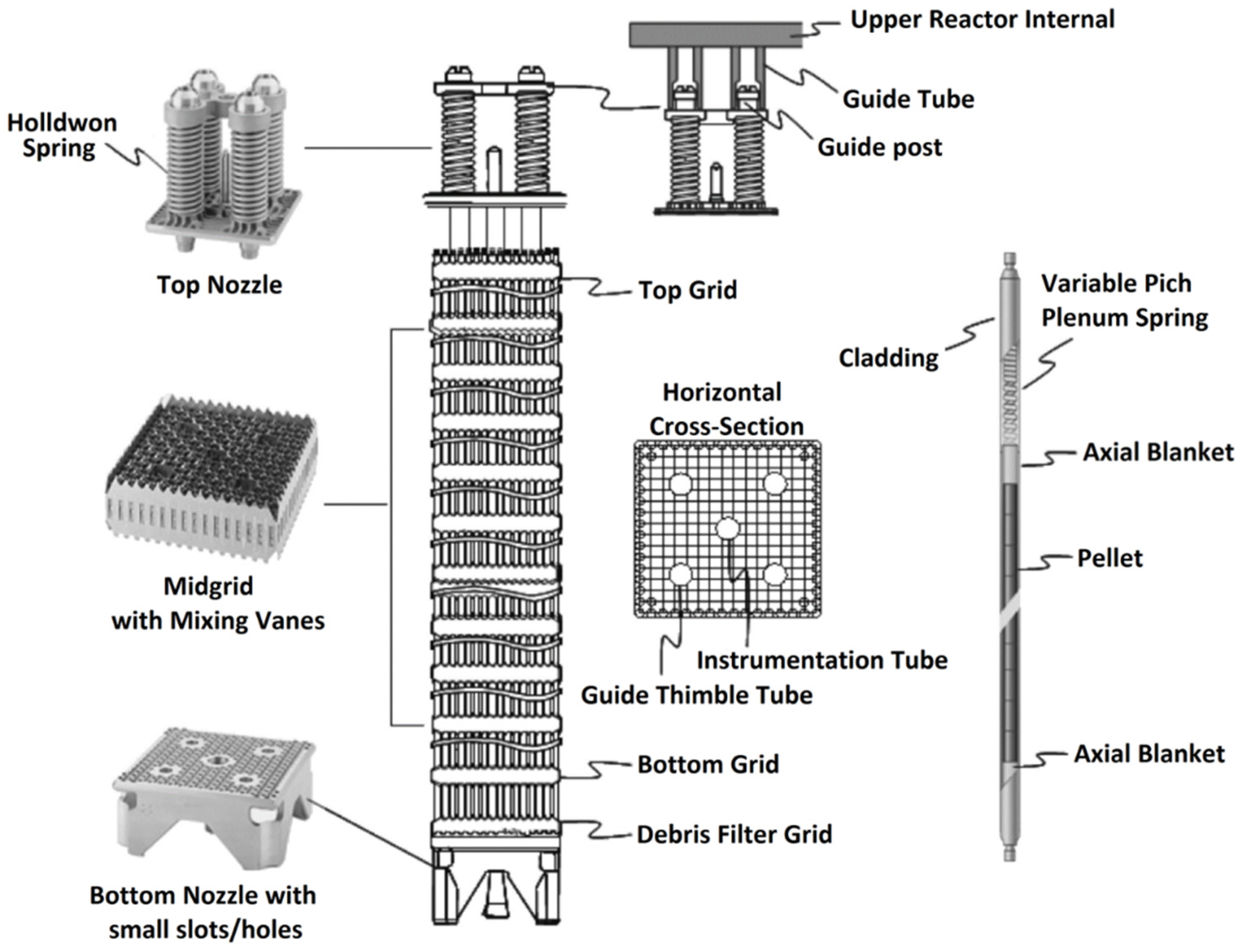
2.1. Target Fuel Rod
2.2. Material Model of the Degraded HBF Cladding and Pellets
2.3. Determination of the Failure of the Fuel Cladding
3. Development of the Simplified Beam Model of a SNF Rod under Pure Bending
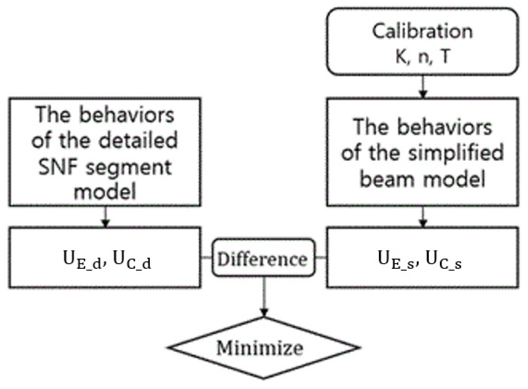
3.1. Strategy of the Model Simplification
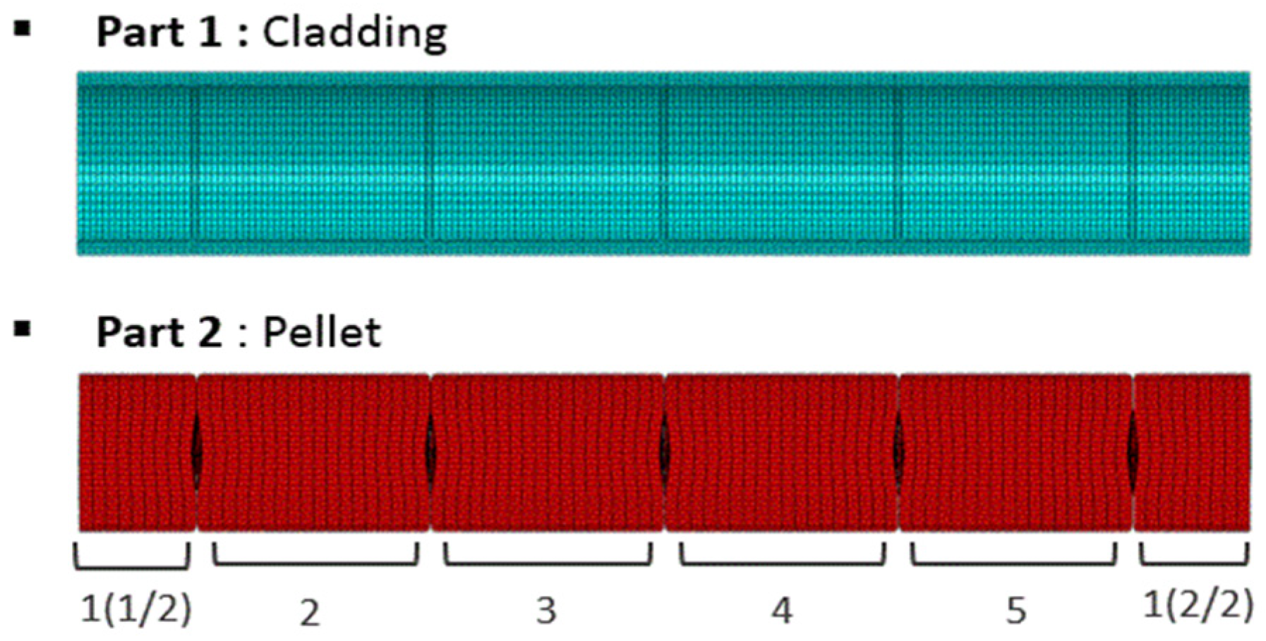
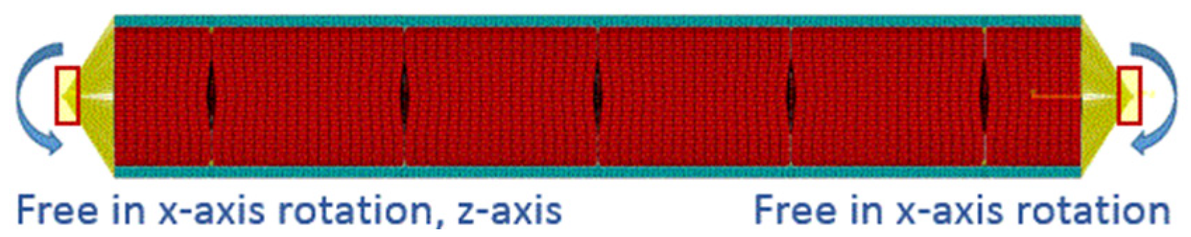
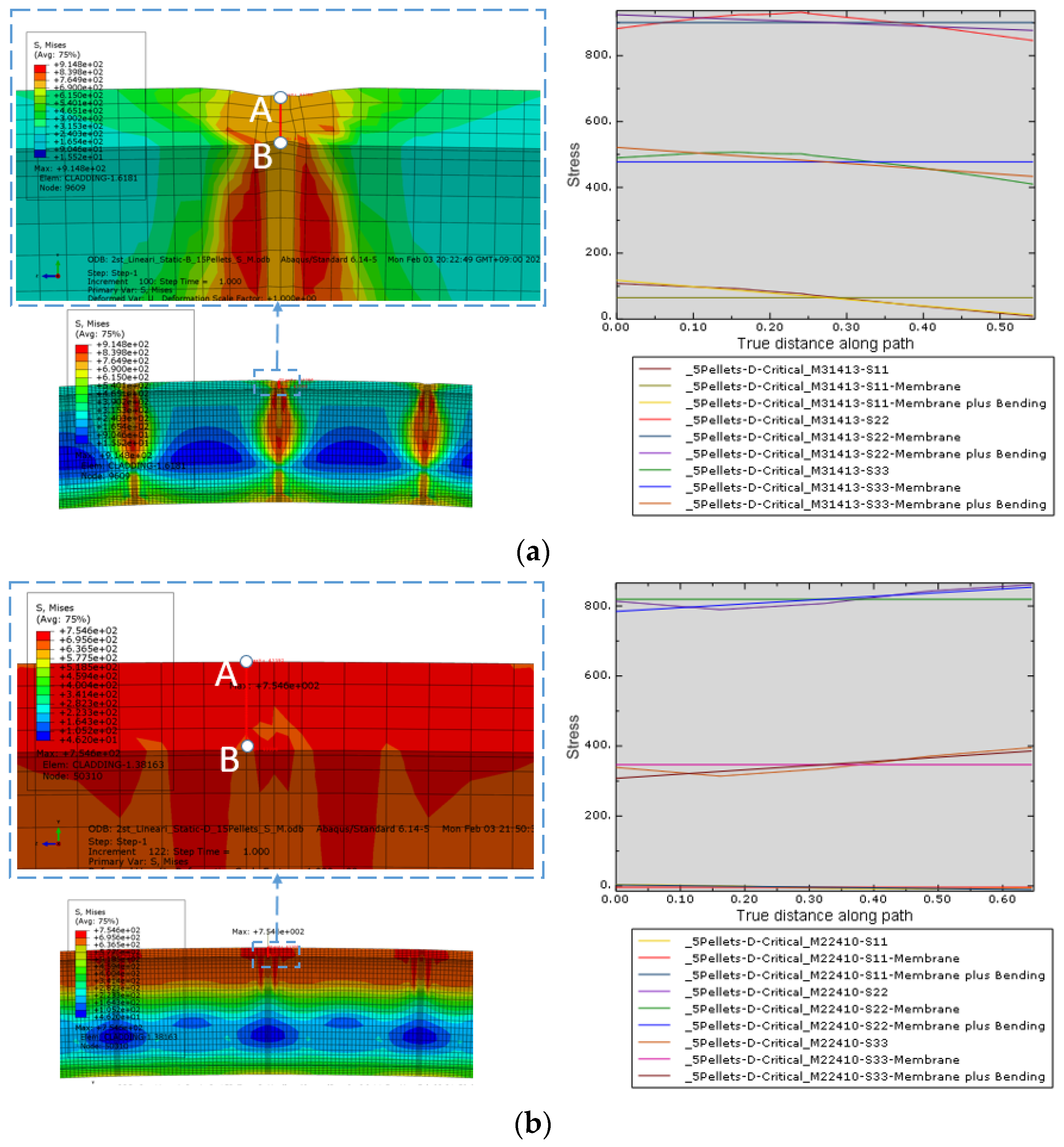
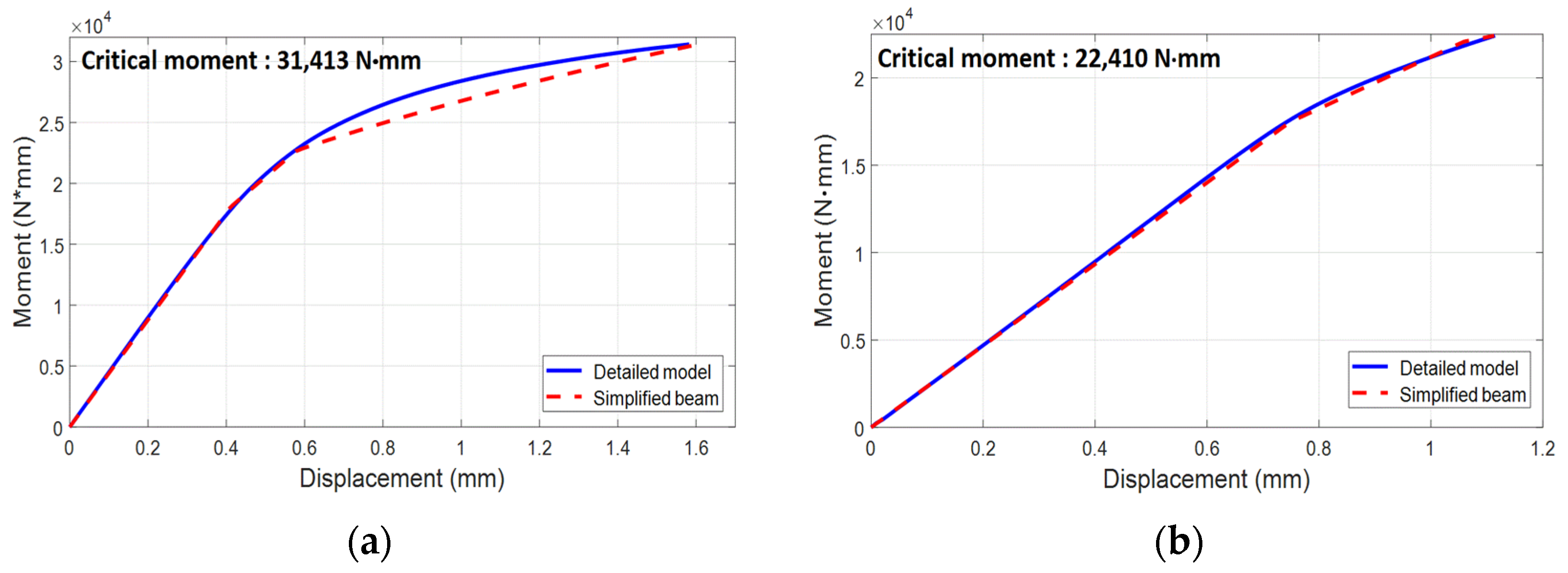
3.2. Detailed Finite Element Model and Results of the Static Analyses
3.3. Parameter Calibration for the Simplified Model
3.4. Discussions on the Failure Limit Criteria of the Cladding with Various Segment Lengths
4. Applicability of the Developed Models in Dynamic Impact Simulations
4.1. Models for Impact Simulation and Impact Conditions
4.2. Results and Discussion
5. Discussion and Conclusions
- -
- In a comparison with the previous work of the authors, it is shown that the stress-based failure criterion is more conservative than the strain-based criteria based on the curvature of the deflected fuel rod.
- -
- The stress correction factors are very effective in the failure prediction of the simplified beam models. However, the specific values of these factors can vary due to a number of factors, such as the shape of the fuel pellets, the material properties of the cladding and pellets, the gaps between the pellets and cladding, etc.
- -
- In the dynamic impact simulations, the stress prediction using the simplified model and the stress correction factor show good accuracy as the drop height approaches the critical drop height. This is natural, because the simplified models were developed focusing on the failure point of the fuel rods.
- -
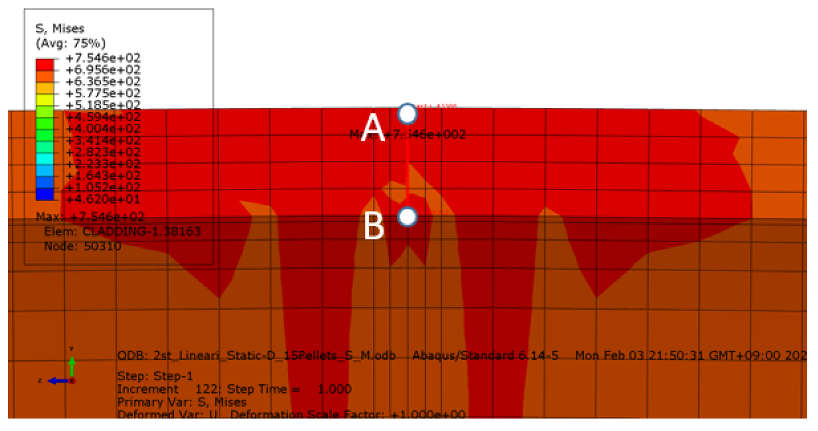
- Although the fully bonded fuel rod deflects less than the fully de-bonded case, earlier failure is predicted with the stress-based failure criterion in the dynamic simulations. It is mainly due to the development of the shear stress in the interface of the fuel pellets and cladding in the fully bonded case. The validity of the failure criterion of the fuel cladding under a complicated 3D stress state should be confirmed with experimental data.
- -
- The discrepancy of simplified model behavior can be reduced by adopting material models with more parameters to be calibrated together with more powerful fitting methods. It is expected that the correlation in the small loading situation can be improved significantly with such efforts.
Author Contributions
Funding
Conflicts of Interest
References
- Ojovan, M.I.; Lee, W.E.; Kalmykov, S.N. An Introduction to Nuclear Waste Immobilization; Elsevier: Amsterdam, The Netherlands, 2019. [Google Scholar]
- Lee, S.H.; Yook, D.S. Review of Spent Nuclear Fuel Dry Storage Demonstration Programs in US. J. Nucl. Fuel Cycle Waste Technol. 2017, 15, 135–149. [Google Scholar] [CrossRef]
- U.S. Nuclear Regulatory Commission. Licensing Requirements for the Independent Storage of Spent Nuclear Fuel, High-Level Radioactive Waste, and Reactor-Related Greater than Class C Waste, Rules and Regulations, Title 10, Part 72; US NRC: Washington, DC, USA, 2010.
- U.S. Nuclear Regulatory Commission. Packaging and Transportation of Radioactive Material, Rules and Regulations, Title 10, Part 71; US NRC: Washington, DC, USA, 2019.
- IAEA Safety Standard. Regulations for the Safe Transport of Radioactive Material; Version 2021; Specific Safety Requirements No. SSR-6; IAEA: Vienna, Austria, 2012. [Google Scholar]
- Choi, W.Y. Evaluation of Hydride Effect on Cladding Integrity under Spent Nuclear Fuel Dry Storage. Master’s Thesis, Kyunghee University, Yongin, Korea, 2018. [Google Scholar]
- Kang, Y.G. Degradation Evaluation of LWR Spent Nuclear Fuel for Dry Storage. Master’s Thesis, Hanyang University, Seoul, Korea, 2019. [Google Scholar]
- U.S. Nuclear Regulatory Commission. Cladding Considerations for the Transportation and Storage of Spent Fuel, Interim Staff Guidance-11 Rev. 3; US NRC: Washington, DC, USA, 2003.
- Jiang, H.; Wang, J.A.; Wang, H. The impact of interface bonding efficiency on high-burnup spent nuclear fuel dynamic performance. Nucl. Eng. Des. 2016, 309, 40–52. [Google Scholar] [CrossRef] [Green Version]
- Wang, J.A.; Wang, H.; Jiang, H.; Bevard, B. High burn-up spent nuclear fuel transport reliability investigation. Nucl. Eng. Des. 2018, 330, 497–515. [Google Scholar] [CrossRef]
- Almomani, B.; Jang, D.; Lee, S. Structural integrity of a high-burnup spent fuel rod under drop impact considering pellet-clad interfacial bonding influence. Nucl. Eng. Des. 2018, 337, 324–340. [Google Scholar] [CrossRef]
- Almomani, B.; Kim, S.; Jang, D.; Lee, S. Parametric study on the structural response of a high burnup spent nuclear fuel rod under drop impact considering post-irradiated fuel conditions. Nucl. Eng. Technol. 2019, 52, 1079–1092. [Google Scholar] [CrossRef]
- Lee, S.; Kim, S. Simplified beam model of high burnup spent fuel rod under lateral load considering pellet-clad interfacial bonding influence. Nucl. Eng. Technol. 2019, 51, 1333–1344. [Google Scholar] [CrossRef]
- Lee, S.; Kim, S. Development of equivalent beam model of high burnup spent nuclear fuel rods under lateral impact loading. Metals 2020, 10, 470. [Google Scholar] [CrossRef] [Green Version]
- Kim, K.; Jang, Y.; Kim, J. In-Reactor Performance of an advanced PWR Fuel, PLUS7, for OPR1000s in Korea. Nucl. Sci. Technol. 2008, 45, 836–849. [Google Scholar] [CrossRef]
- Geelhood, K.J.; Beyer, C.E.; Luscher, W.G. PNNL Stress/Strain Correlation for Zircaloy (PNNL-17700); Pacific Northwest National Laboratory: Washington, DC, USA, 2008. [Google Scholar]
- Adkins, H.; Geelhood, K.; Koeppel, B.; Coleman, J.; Bignell, J.; Flores, G.; Wang, J.A.; Sanborn, S.; Spears, R.; Klymyshyn, N. Used Fuel Disposition Campaign, Used Nuclear Fuel Loading and Structural Performance under Normal Conditions of Transport—Demonstration of Approach and Results on Used Fuel Performance Characterization (FCRD-UFD-2013-000325); U.S. Department of Energy: Washington, DC, USA, 2013.
- U.S. Nuclear Regulatory Commission. A Pilot Probabilistic Risk Assessment of a Dry Cask Storage System at a Nuclear Power Plant (NUREG-1864); US NRC: Washington, DC, USA, 2010.
- EPRI. Spent Fuel Transportation Applications Assessment of Cladding Performance: A Synthesis Report (EPRI 1015048); Electric Power Research Inst.: Palo Alto, CA, USA, 2007. [Google Scholar]
- EPRI. Fuel-Assembly Behavior under Dynamic Impact Loads Due to Dry-Storage Cask Mishandling (EPRI-NP—7419); Electric Power Research Inst.: Palo Alto, CA, USA, 1991. [Google Scholar]
- Choi, W.; Kim, T.; Seo, K. Shape optimization of a torus seal under multiple loading conditions based on the stress categories in the ASME code section III. Nucl. Eng. Des. 2011, 241, 2653–2659. [Google Scholar] [CrossRef]
- Michael, S. ABAQUS/Standard User’s Manual; Version 6.9; Dassault Systèmes Simulia Corp: Providence, RI, USA, 2009. [Google Scholar]
- Li, H.; Ding, Q.; Huang, X. A New Method of Stress Linearization for Design by Analysis in Pressure Vessel Design. Appl. Mech. Mater. 2014, 598, 194–197. [Google Scholar] [CrossRef]
- Bratton, R.; Jessee, M.; Wieselquist, W. Rod Internal Pressure Quantification and Distribution Analysis Using FRAPCON (FCRD-UFD-2015-000636); US Department of Energy: Washington, DC, USA, 2015.
- Velden, A.; Koch, P. Isight Design Optimization Methodologies. In ASM Handbook Volume 22B, Metals Process Simulation; Furrer, D.U., Semiatin, S.L., Eds.; ASM International: Geauga County, OH, USA, 2010. [Google Scholar]
- Ingber, L. Adaptive Simulated Annealing (ASA): Lessons learned. Control Cybern. 1996, 25, 33–54. [Google Scholar]


| Parameter | Value |
|---|---|
| Cladding length (L) | 4.094 m |
| Outer diameter of cladding (OD) (ro) | 4.75 mm |
| Inner diameter of cladding (ID) (ri) | 4.178 mm |
| Diametral gap | |
| Distance between two sequent spacer grids | 396.9 mm |
| Area moment of inertia ofr the cladding (Ic) | 160.508 mm4 |
| Area moment of inertia for the pellet (Ip) | 239.291 mm4 |
| Pellets diameter | 8.191 mm |
| Pellets length | 11.34 mm |
| Number of pellets in full fuel rod | 350 |
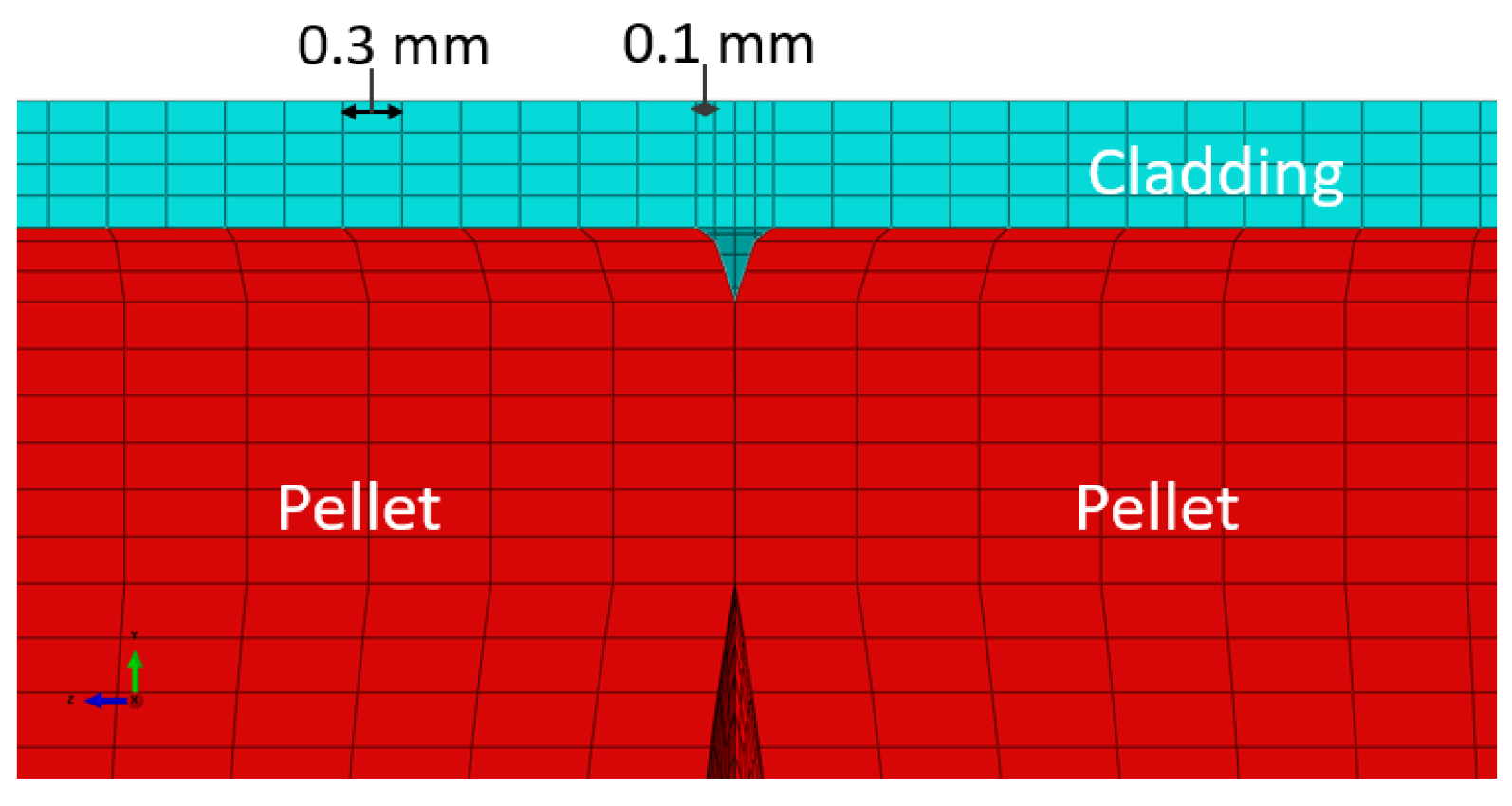
| Pellets hollow depth | 0.3 mm |
| Pellets hollow radius | 14 mm |
| Pellets hollow apparent radius | 2.95 mm |
| Pellet edge chamfer radius | 3.55 mm |
| Pellets edge chamfer depth | 0.16 mm |
| Gap With adjacent pellets | No gap |
| Total weight of single rod (W) | 2.58 kg |
| Fraction of theoretical density of UO2 (%TD) | 95% |
| Assembly weight | 639 kg |
| Number of rods | 236 |
| Number of spacer grids | 12 |
| Parameters | Mechanical Properties |
|---|---|
| 1. Zircaloy cladding (SRA Zry-4) | |
| a. Mass density (ρc) | 6590 kg/m3 |
| b. Modulus of elasticity (E) | 75.22 GPa |
| c. Strength coefficient (K) | 14.43 GPa |
| d. Strain hardening exponent (n) | 0.159 |
| e. Strain rate exponent (m) | 0.015 |
| f. Shear modulus (G) | 28.28 GPa |
| g. Poisson’s ratio (v) | 0.33 |
| h. Uniform plastic elongation (UE) | 0.022 |
| i. Yield strength (σy) | 644.79 MPa |
| j. Ultimate tensile strength (σe+p) | 788.68 MPa |
| 2. Fuel (uranium dioxide (UO2)) | - |
| a. Mass density (ρp) | 10,440 kg/m3 |
| b. Modulus of elasticity (E) | 168.3 GPa |
| c. Poisson’s ratio (v) * | 0.32 |
| d. Yield strength (σy) * | 2146 MPa |
| Interfacial Bonding Condition | Interface | Modeling |
|---|---|---|
| Fully bonded | Pellet–Pellet | Frictionless hard contact |
| Pellets–Cladding | Tie constraints | |
| Fully de-bonded | Pellet–Pellet | Frictionless hard contact |
| Pellets–Cladding | Frictionless hard contact |
| Interfacial Bonding Condition | Optimal Parameter Values | Critical Moment | UE_s (dev.) | UC_s (dev.) | ||||
|---|---|---|---|---|---|---|---|---|
| K (GPa) | n | T (mm) | Value (MPa) | (dev.) | ||||
| Fully bonded | 2.180 | 0.359 | 1.23 | 31.4 N·m | 0.357 (0.0%) | 1.605 (1.0%) | 422 | 44% |
| Fully de-bonded | 1.888 | 0.415 | 1.68 | 22.4 N·m | 0.390 (0.4%) | 1.113 (0.0%) | 245 | 67% |
| Cases | Number of Pellets | Length (mm) | Critical Moment (N·mm) | Model | Displacement (UC) | Stress | ||
|---|---|---|---|---|---|---|---|---|
| Value (mm) | Dev. (%) | Value (MPa) | Dev. (%) | |||||
| 1 | 5 (reference) | 56.7 | 31,413 | Detailed | 1.58 | 1.0 | 749 | 44 |
| Simplified | 1.61 | 422 | ||||||
| 2 | 10 | 113.4 | Detailed | 5.84 | 0.6 | 749 | 44 | |
| Simplified | 5.87 | 423 | ||||||
| 3 | 15 | 170.1 | Detailed | 12.98 | 1.9 | 751 | 44 | |
| Simplified | 12.74 | 423 | ||||||
| 4 | 20 | 226.8 | Detailed | 22.04 | 0.5 | 747 | 44 | |
| Simplified | 21.16 | 423 | ||||||
| 5 | 25 | 283.5 | Detailed | 34.50 | 1.8 | 752 | 44 | |
| Simplified | 33.88 | 423 | ||||||
| 6 | 30 | 340.2 | Detailed | 48.85 | 1.2 | 752 | 44 | |
| Simplified | 48.28 | 423 | ||||||
| Cases | Number of Pellets | Length (mm) | Critical Moment (N·mm) | Model | Displacement (UC) | Stress | ||
|---|---|---|---|---|---|---|---|---|
| Value (mm) | Dev. (%) | Value (MPa) | Dev. (%) | |||||
| 1 | 5 (reference) | 56.7 | 22,410 | Detailed | 1.11 | 0 | 749 | 67 |
| Simplified | 1.11 | 245 | ||||||
| 2 | 10 | 113.4 | Detailed | 3.97 | 2.9 | 749 | 67 | |
| Simplified | 4.09 | 245 | ||||||
| 3 | 15 | 170.1 | Detailed | 8.64 | 2.9 | 750 | 67 | |
| Simplified | 8.90 | 245 | ||||||
| 4 | 20 | 226.8 | Detailed | 15.04 | 3.1 | 749 | 67 | |
| Simplified | 15.52 | 245 | ||||||
| 5 | 25 | 283.5 | Detailed | 23.19 | 3.1 | 749 | 67 | |
| Simplified | 23.93 | 245 | ||||||
| 6 | 30 | 340.2 | Detailed | 33.02 | 3.1 | 749 | 67 | |
| Simplified | 34.09 | 245 | ||||||
| No. | Drop Height (m) | Model | Max. Displacement | Stress * | |||
|---|---|---|---|---|---|---|---|
| Value (mm) | Dev. (%) | Correction Factor | Value (MPa) | Dev. (%) | |||
| 1 | 0.3 | Detailed | 0.42 | 9.9 | 1.78 | 437 | 62 (31) |
| Simplified | 0.46 | 168 (300) | |||||
| 2 | 0.5 | Detailed | 0.54 | 5.0 | 674 | 59 (28) | |
| Simplified | 0.57 | 274 (487) | |||||
| 3 | 1.0 | Detailed | 0.80 | 3.3 | 697 | 55 (21) | |
| Simplified | 0.85 | 308 (548) | |||||
| 4 | 1.5 | Detailed | 0.99 | 8.4 | 757 | 58 (0.6) | |
| Simplified | 1.16 | 423 (752) | |||||
| No. | Drop Height (m) | Model | Max. Displacement | Stress * | |||
|---|---|---|---|---|---|---|---|
| Value (mm) | Dev. (%) | Correction Factor | Value (MPa) | Dev. (%) | |||
| 1 | 0.3 | Detailed | 0.56 | 12.3 | 3.06 | 322 | 61 (18) |
| Simplified | 0.63 | 124 (379) | |||||
| 2 | 0.5 | Detailed | 0.54 | 15.3 | 433 | 64 (9.0) | |
| Simplified | 0.57 | 156 (478) | |||||
| 3 | 1.0 | Detailed | 1.00 | 19.0 | 638 | 66 (4.2) | |
| Simplified | 1.19 | 217 (664) | |||||
| 4 | 1.5 | Detailed | 1.23 | 10.8 | 727 | 67 (0.1) | |
| Simplified | 1.47 | 240 (734) | |||||
| Drop Height (m) | Fully Bonded Fuel Rod | Fully De-Bonded Fuel Rod |
|---|---|---|
| 0.3 | 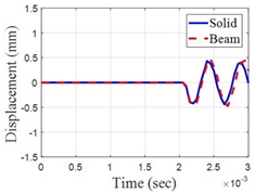 | 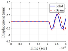 |
| 0.5 |  | 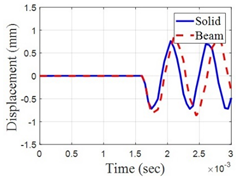 |
| 1.0 | 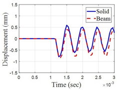 | 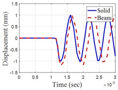 |
| 1.5 |  | 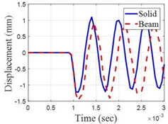 |
Publisher’s Note: MDPI stays neutral with regard to jurisdictional claims in published maps and institutional affiliations. |
© 2021 by the authors. Licensee MDPI, Basel, Switzerland. This article is an open access article distributed under the terms and conditions of the Creative Commons Attribution (CC BY) license (https://creativecommons.org/licenses/by/4.0/).
Share and Cite
Kim, S.; Lee, S. Simplified Model of a High Burnup Spent Nuclear Fuel Rod under Lateral Impact Considering a Stress-Based Failure Criterion. Metals 2021, 11, 1631. https://doi.org/10.3390/met11101631
Kim S, Lee S. Simplified Model of a High Burnup Spent Nuclear Fuel Rod under Lateral Impact Considering a Stress-Based Failure Criterion. Metals. 2021; 11(10):1631. https://doi.org/10.3390/met11101631
Chicago/Turabian StyleKim, Seyeon, and Sanghoon Lee. 2021. "Simplified Model of a High Burnup Spent Nuclear Fuel Rod under Lateral Impact Considering a Stress-Based Failure Criterion" Metals 11, no. 10: 1631. https://doi.org/10.3390/met11101631