Abstract
To study the effect of reprocessing on the microstructure and corrosion resistance of Zr-Sn-Nb alloy, the original plates of Zr-Sn-Nb alloy were hot-rolled, cold-rolled and recrystallized to obtain the reprocessed plates. The microstructure of both plates was observed with a scanning electron microscope (SEM), a transmission electron microscope (TEM) and electron backscattering diffraction (EBSD). The original plates and reprocessed plates were put into a static autoclave for 300 days in 360 °C/18.6 MPa water. The relationship between the microstructure and corrosion resistance of the Zr-Sn-Nb alloy was discussed. The coarse deformation grains with twins and fine recrystallized grains were obtained, and grain sizes became smaller. The Ostwald ripening of second phase particles (SPPs) happened, and the average size of SPPs increased. Some SPPs changed from an HCP structure to an FCC structure. Reprocessing made the transition advance, which is related to the accelerated evolution of cracks in the oxide film and the increase in metal-oxide film interface roughness. The deterioration of corrosion resistance is closely related to the change of grain size, SPP size and SPP structure.
1. Introduction
Zirconium alloys are the only cladding material used in pressurized water reactors (PWRs) because of the low-thermal neutron-capture cross-section, excellent radiation resistance, reasonable mechanical properties and unique corrosion resistance in high-temperature water. In the past 30 years, Zircaloy such as Zr-2 and Zr-4 has been widely used in PWRs and has shown good application performance [1]. With the development of PWRs toward deepening the burn-up of nuclear fuel and extending the reload cycle, higher requirements are put forward for the performance of zirconium alloys. Thereupon, Zr-Sn-Nb alloys with better corrosion, radiation, creep and fatigue resistance have been developed. Many Zr-Sn-Nb alloys, such as ZIRLOTM [2], E635 [3], HANA [4], N18 [5] and N36 [6], have been applied in PWRs as fuel-cladding tubes and structure materials.
Currently, the life-limiting factors of zirconium cladding can be attributed to in-pile corrosion, irradiation growth, creep properties, hydrogen pickup, delayed hydrogen cracking (DHC), etc. [7]. Among them, the corrosion resistance of zirconium alloys is closely related to the integrity of nuclear fuel and the stable and reliable operation of PWRs [8]. Investigation has shown that the kinetics of high-temperature oxidation are similar in shape for both zirconium and zirconium alloys, and the similarity holds irrespective of the oxidizing media for oxygen, air, water or steam [9]. The kinetics can be roughly divided into two stages, namely the pre-transition stage with a slow corrosion rate and the post-transition stage with an accelerated rate [8]. The point at which the kinetics change from first mode to second mode has been variously termed as the “breakaway”, “transition time” or “breakdown” [10,11]. Transition time is mainly affected by the oxidizing media. For example, the time to transition for pure zirconium is much longer in oxygen than in air [12]; also, higher water pressure causes a transition at a thicker oxide thickness [13]. From the oxidation kinetics of zirconium alloys, the prolonging of the time to transition and the reduction in oxidation rate mean that zirconium alloys have better corrosion resistance. Improving the corrosion resistance of zirconium alloys has always been an important development field of general concern.
There are two ways to enhance the corrosion resistance of zirconium alloys: adjusting the alloy composition and optimizing the production process. In terms of alloy composition adjustment, the main alloying elements such as Sn [14], Nb [15], Fe [16] and Cr [17] and micro-alloy elements such as Cu, Mo and V [7] have great influence on corrosion resistance. The solubility of Sn in Zr matrix is high. In-pile and out-of-pile trials have proved that low Sn is beneficial to improving corrosion resistance [7,14]. In laboratory studies, Sn is shown to stabilize the tetragonal ZrO2 (t-ZrO2) phase, resulting in the presence of large tetragonal grains, which will damage the oxide after t-ZrO2 transformation [14]. Most alloying elements have low solubility in Zr matrix. They are the SPPs forming elements, such as Nb, Fe, Cr, Cu, Mo and V [7,15,17]. Earlier studies suggest that SPP size is the main factor affecting the corrosion of zirconium alloys. The Nb-containing zirconium alloys with 50 nm SPPs have excellent corrosion resistance. When SPP size is coarsened to 200–300 nm, corrosion resistance is greatly reduced [18]. However, the relevant mechanisms remain unclear. With the development and application of advanced devices, it has been possible to identify the microstructure and microchemical properties of SPPs before and after oxidation. Secondary ion mass spectrometer (SIMS) and three-dimensional atomic probe tomography (3D-APT) experiments have proved that hydrogen may prefer to gather around SPPs [19,20], and SPPs always experience delayed oxidation [21]; it is easy to conclude that SPPs may serve as cathodes, fast channels of electrons or reduction positions of H+ [7]. The corrosion behavior of SPPs embedded in oxide films is greatly related to their physical and chemical properties. These differences in SPPs have a profound impact on corrosion behavior [22]. In terms of production process optimization, the microstructure of zirconium alloys can be well-regulated and excellent corrosion resistance can be obtained by applying a proper production process and heat treatment. For instance, using a low-temperature process and controlling the cumulative annealing parameters, M5 and X5A zirconium alloy can obtain fine and dispersed SPPs, which is conducive to improving corrosion resistance [23]. Production processing is closely related to microstructure, and microstructure evolution plays an important role in corrosion resistance, so microstructure evolution and its impact on corrosion resistance have been of wide concern.
Reprocessing, including hot rolling, cold rolling and recrystallization annealing, is required when original plates of zirconium alloys are manufactured into a fuel assembly. Some research [24,25,26] has been carried out on the reprocessing of Zr-Sn-Nb alloy, but only concerned with microstructure evolution; the influence of reprocessing and microstructure on corrosion resistance needs to be clarified. In the following sections, microstructure evolution and its influence on the corrosion resistance of Zr-Sn-Nb alloy plates during reprocessing are reported and discussed, and an attempt has been made to relate reprocessing and microstructure to corrosion resistance.
2. Materials and Methods
2.1. Alloy and Materials
The composition of the Zr-Sn-Nb alloy selected in this study is shown in Table 1. There are two kinds of test materials. Original plates were obtained by vacuum consumable melting, forging, quenching, hot rolling and several courses of cold rolling and annealing. Reprocessed plates were obtained from reprocessing the original plates. Reprocessing includes hot rolling, cold rolling and recrystallization annealing. Although zirconium alloy rolled at the β phase (temperature usually higher than 850 °C) has better deformative ability, zirconium alloys may easily be polluted by harmful gases (nitrogen, hydrogen, oxygen, etc.), resulting in the formation of a brittle layer on the surface and the increase in the inhomogeneous deformation of the plate during hot rolling. To obtain good plasticity and reduce gas pollution as much as possible, the hot-rolling temperature of zirconium alloy should not be too high. In this study, the original plates were hot rolled at the upper temperature of the α phase (about 780 °C). The thickness of the original plates was about 4.4 mm. After hot rolling, the thickness was reduced by 2.9 mm to 1.5 mm, so the reduction was about 66%. Cold rolling occurred after hot rolling. Plates was cold rolled at room temperature. The thickness changed from 1.5 mm to 1.4 mm after cold rolling, so the reduction was less than 10%. After cold rolling, plates were recrystallization annealed at 580 °C for 1.5 h.

Table 1.
Chemical composition of Zr-Sn-Nb alloy (wt%).
2.2. Microscopic Analysis of Zirconium Matrix
The characteristics of grains and SPPs were analyzed. The observation surface was TD-RD, as shown in Figure 1. EBSD (Oxford Instruments, Abingdon, UK) was used to observe grains. After vibro-polishing for several hours, samples were chemically polished for 15 s using a metallographic etching solution for zirconium alloy (10 vol.% hydrofluoric acid, 45 vol.% nitric acid and 45 vol.% distilled water) at room temperature. The shape, size and distribution of SPPs were analyzed by SEM (FEI, Columbia, MD, USA). Samples were chemical etched with a solution of 60 vol.% glycerol, 30 vol.% hydrofluoric acid and 10 vol.% nitric acid for about 30 s at room temperature. TEM (JEOL, Akishima-shi, Japn) was used to characterize SPPs at higher magnification. The thickness of a sample was chemically reduced to 70–100 μm using metallographic etching solution and then carefully ground to 30–40 μm. The thin foil was finally prepared at 228 K by twin-jet polishing with a solution of 10% HClO4 (Sinopharm, Shanghai, China) and 90% C2H5OH (Sinopharm, Shanghai, China).
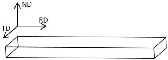
Figure 1.
Schematic diagram of sample observation surface.
2.3. Corrosion Experiment
Plates were cut into 30 mm × 20 mm × 1.4 mm sheets for the corrosion test. Before corrosion, specimens were pickled in the standard metallographic etching solution for 1 min to get a shiny surface. These specimens were moved immediately into the flowing water after pickling. Rinsing in the flowing water lasted for about 10 min and then specimens were transferred into the boiling deionized water for another 10 min to eliminate the influence of fluorine. The corrosion test was carried out in a static autoclave with deionized water at 360 °C/18.6 MPa following the ASTM-G2/G2M-06 standard (corrosion testing of products of zirconium, hafnium and their alloys in water at 680 °F [360 °C] or in steam at 750 °F [400 °C]). Specimens were taken and weighed at a certain interval, and corrosion resistance was evaluated by weight gain. In this study, at least three parallel samples were left in the autoclave to ensure an average measuring of weight gain.
2.4. Microscopic Analysis of Oxide Films
TEM was used to analyze the oxide films. The preparation of cross-sectional samples by the in situ lift-out (INLO) focused ion beam (FIB) method was described in an earlier publication [9].
3. Results
3.1. Microstructure of Zirconium Matrix
The basic metallography of the original plates and reprocessed plates taken from EBSD is shown in Figure 2. The grains of the original plates show as equiaxed in shape, with an average grain size of about 2.97 μm. Few deformed grains appear in the matrix, indicating that the original plates have been recrystallized completely. The microstructure of the reprocessed plates is mainly composed of coarse deformed grains with twins inside, as shown in Figure 2b. The sizes of such large grains are 10–20 μm. Fine equiaxed grains appear, indicating that the reprocessed plates have undergone dynamic recrystallization. During reprocessing, grains are not obviously deformed, original grains are only slightly elongated along the RD direction, and the deformation energy is not enough to induce numerous continuous recrystallizations, so there are few recrystallized grains. The average grain size of the reprocessed plates is about 1.52 μm.
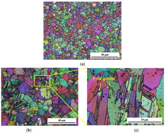
Figure 2.
Schematic diagram of sample observation surface: (a) grain structure of original plates; (b) grain structure of reprocessed plates at low magnification; (c) grain structure of reprocessed plates at high magnification.
The pole figures and inverse pole figures of the original plates and reprocessed plates is displayed in Figure 3. The original plates exhibit a <0001> texture parallel to ND (<0001>//ND), and the [0001] basal pole tilts 20°–30° along the TD, as shown in Figure 3a and b. This is a typical recrystallized texture of zirconium alloy [24]. Reprocessed plates show a typical rolling texture of zirconium alloys, which was characterized as <0001>//ND (Figure 3c,d). Murty et al. [26] found that for the annealed zirconium alloys, <1120> aligns parallel to the rolling direction. However, in this study, reprocessed plates do not show this characteristic.
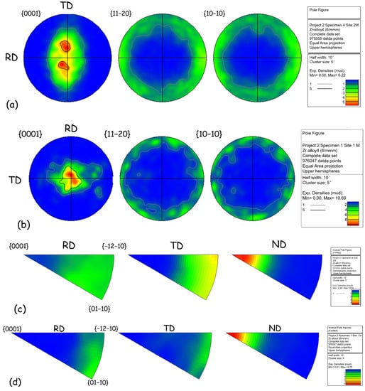
Figure 3.
Pole figures of (a) original plates, (c) reprocessed plates and inverse pole figures of pole figure of (b) original plates and (d) reprocessed plates.
The morphology and distribution of SPPs are illustrated in Figure 4. SPPs of the original plates and reprocessed plates are spherical or ellipsoidal and distributed in the grain or on the grain boundary uniformly. The dispersive SPPs can effectively improve corrosion resistance of Nb-containing zirconium alloys [27]. Comparing the original plates with the reprocessed plates, it is easy to find that there are more large SPPs in the reprocessed plates. The size of SPPs was counted by Image-Pro Plus, and results are shown in Figure 5 and Table 2. The average size of SPPs of the reprocessed plates is 240 nm, which is larger than of the original plates (191 nm). Moreover, reprocessed plates have more SPPs with a size greater than 200 nm, indicating that SPPs have undergone Ostwald ripening during reprocessing [28]; that is, SPPs with a small size have dissolved and with a large size have grown.
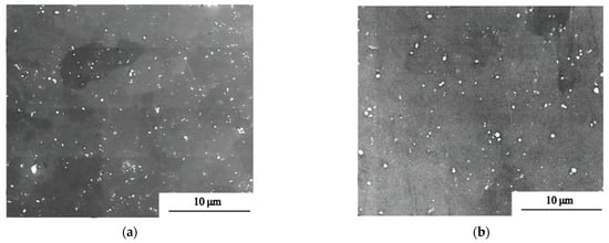
Figure 4.
SEM images of (a) original plates and (b) reprocessed plates.
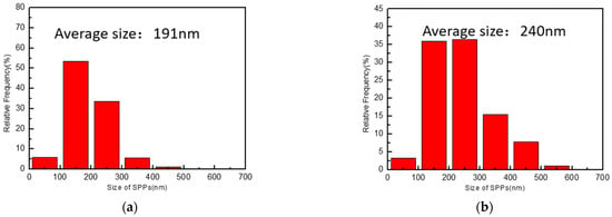
Figure 5.
SPP size distribution of (a) original plates and (b) reprocessed plates.

Table 2.
Quantitative statistics of SPP size of original plates and reprocessed plates.
The morphology of SPPs at high magnification and the selected-area electron diffraction patterns of SPPs were obtained by TEM, as shown in Figure 6. There are Zr(Fe,Cr)2 with an HCP structure and with an FCC structure in the original plates. The numbers of SPPs with these two structures are almost equal. Most of SPPs in reprocessed plates are Zr(Fe,Cr)2 with an HCP structure; few are Zr(Fe,Cr)2 with an FCC structure. The solid solubility of Nb in α-Zr is low, less than 0.3% [15], so almost all Nb dissolved in the matrix and the SPPs in this study contained no Nb.
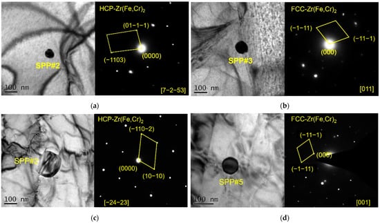
Figure 6.
TEM and SAED images: (a) Zr(Fe,Cr)2 with HCP structure in original plates; (b) Zr(Fe,Cr)2 with FCC structure in original plates; (c) Zr(Fe,Cr)2 with HCP structure in reprocessed plates; and (d) Zr(Fe,Cr)2 with FCC structure in reprocessed plates.
The results of above-mentioned analysis show that reprocessing may change the structure of SPPs (HCP to FCC). Some studies found that Zr(Fe,Cr)2 particles rapidly cooled in the β or α + β phase region are the FCC structure [29], while after long-time annealing in α phase region, Zr(Fe,Cr)2 particles are the HCP structure [30]. Reprocessing includes hot rolling at the upper-limit temperature of the α phase region and annealing at the α phase region, which promotes the transformation of an HCP structure into an FCC structure. It should be pointed out that Shen et al. [31] believed that the transition from an FCC structure to HCP structure was extremely slow, so a small amount of SPPs still remain with an FCC structure in this study.
3.2. Corrosion Behavior
The corrosion kinetics of zirconium alloys can be divided into two stages, namely the pre-transition stage and the post-transition stage [8]. The point at which the kinetics change from first mode to second mode has been variously termed as the “breakaway”, “transition time” or “breakdown” [10,11]. It is generally considered that the transition starts when oxide film thickens to 2–3 μm (weight gain increases to 30–50 mg/dm2) [32]. Differences in alloying elements, manufacturing processes and corrosion conditions may change the transition time. In this study, the points with a weight gain of less than 40 mg/dm2 were selected to fit pre-transition, and the remaining points were used for linear fitting.
For pre-transition:
ΔW = k1 · tn
For post-transition:
where ΔW is the weight gain of sample in unit of mg/dm2, t is exposure time, n is the time index for pre-transition, k1 is the rate constant for pre-transition, k2 is the rate constant for post-transition and C is another constant.
ΔW = k2 · t + C
The corrosion resistance in 360 °C/18.6 MPa deionized water was studied by autoclave. Zr-4 was taken as the reference alloy. The weight gain profile is shown in Figure 7. Obviously, the corrosion resistance of different materials is quite different. Zr-4 has the largest weight gain of 240.85 mg/dm2 in 600 days, which is nearly twice that of the original plates. The original plates show the best corrosion resistance with the lowest weight gain; the transition occurred in 210 days. Reprocessed plates also oxidized slowly until 170 days, after which it gained weight faster.
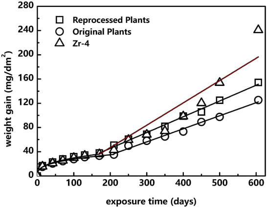
Figure 7.
Corrosion kinetics of different materials.
A power-law equation and linear equation were used for pre-transition and post-transition to obtain the values of k1, k2 and n. The result is shown in Table 3. The value of n is between 0.33 and 0.36, following a cubic law rather than a parabolic law, which is consistent with the study by Cox [8]. The simulation results of Couet et al. [33] show that the n value of the Nb-containing zirconium alloy can reach 0.5 in the pre-transition stage, showing an obvious parabolic law, but their corrosion model does not consider the effect of SPPs on corrosion behavior. For the Nb-containing zirconium alloys with dispersive SPPs, such as Zr-2.5Nb, the n value is about 0.37 [34], which is close to our result. The k1 value is between 5.6 and 6.8 in this study. The study of Wei et al. [35] on Zr-4, Zirlo and low-tin Zirlo at 360 °C indicated that the k1 value is in the range of 4–8, which is similar to our result. Liao et al. [7] found that the k1 value of zirconium alloy at 500 °C is between 7 and 12, which is greater than the k1 value in this study. This is because k1 represents the diffusion rate of the media (such as O2− or OH−) from the surface to the interface, following the Arrhenius equation [1], and its value increases with increasing temperature.

Table 3.
Fitting results for pre-transition and post-transition.
The k2 value is directly related to the weight gain, so it can intuitively reflect the long-term corrosion resistance of the material. The k2 value of three materials in this study are ranked as Zr-4, reprocessed plates and original plates, so the corrosion resistance is ranked as original plates, reprocessed plates and Zr-4. Some studies [36] indicate that the corrosion behavior of the pre-transition stage has great influence on the post-transition stage. Since the transition marks the stage at which the oxide film breaks down, the early occurrence of the transition would largely accelerate the corrosion deterioration of zirconium alloy. Therefore, with larger k1, n and earlier occurrence of the transition, the corrosion resistance in the post-transition stage becomes worse, causing a larger k2 value.
3.3. Microstructure of Oxide Film
The cross-sectional morphology of the original plates and reprocessed plates corroded for 100 days and 300 days were analyzed by TEM, as shown in Figure 8, Figure 9 and Figure 10. The morphologies of the samples corroded for 100 days and 300 days are similar. The inner layers of oxide film are mainly columnar crystal structures (Figure 8d–f and Figure 9d,e), the grains grow along the direction perpendicular to the oxide/metal (O/M) interface, and the outer oxide layers are composed of equiaxed crystals (Figure 8b,c and Figure 9b,c). Oxide films with such a double-layer structure have been reported in much of the literature [9,37]. Comparing samples corroded for 100 days with those corroded for 300 days, the thicknesses of the equiaxed crystal zones are almost the same, about 0.4–0.7 μm, and the thickness of the columnar crystal region increases with exposure time. Ni [9] found that in the early stage of zirconium alloy oxidation, a thin layer of equiaxed crystal region was formed first, and then columnar crystals appeared. With the further oxidation of the zirconium matrix, columnar crystals are transformed into equiaxed crystals gradually, so the equiaxed region grows gradually. These results show that the equiaxed region grows to the thickest before transition and remains unchanged after transition. There are some defects in oxide film, among which are that the columnar crystal region is dominated by cracks (Figure 9a and Figure 10a,b) and the equiaxed crystal region is dominated by micro-voids and microcracks (Figure 8a and Figure 9a). Zr(Fe,Cr)2 with an HCP structure appears in the oxide films of reprocessed plates, and defects appear along with the SPPs (Figure 9f,g). It has been reported that SPPs are embedded in the oxide film at the beginning of oxidation, and then they undergo delayed oxidation [22]. In this study, SPPs were mainly composed of Zr, Fe and Cr, and their P.B. ratios are large. The P.B. ratio of Zr is 1.56, of Fe is 1.77 and of Cr is 2.02 [7], so the oxidation of SPPs will cause volume expansion, change the stress distribution around SPPs and then destroy the oxide film and cause cracks.
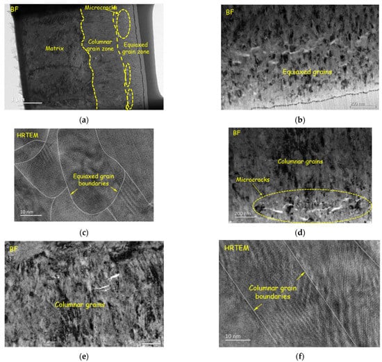
Figure 8.
Oxide morphology of original plates corroded for 100 days: (a) overall morphology; (b) TEM image of equiaxed grains zone; (c) HRTEM image of equiaxed grains zone; (d) TEM image of columnar grains zone, with some microcracks; (e) TEM image of columnar grains zone; and (f) HRTEM image of columnar grains zone.

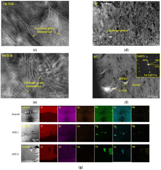
Figure 9.
Oxide morphology of reprocessed plates corroded for 100 days: (a) overall morphology; (b) TEM image of equiaxed grains zone; (c) HRTEM image of equiaxed grains zone; (d) TEM image of columnar grains zone; (e) HRTEM image of columnar grains zone; (f) TEM and SAED image of SPPs embedded in oxide film, some cracks appear around SPPs; and (g) EDS results, which prove cracks (the dark part of the element distribution images) appear along with SPPs (concentration part of Fe, Cr and Nb) again.

Figure 10.
Oxide morphology of (a) original plates and (b) reprocessed plates corroded for 300 days.
Compared with the original plates, the defects in oxide film of the reprocessed plates evolved faster; after corroding for 100 days, the large-scale cracks (about 500 nm) appeared (Figure 9a). At the same time, it was found that longitudinal cracks and transverse cracks were interconnected, which may be the reason for the earlier transition of reprocessed plates [9].
Some studies indicate that the undulation of the O/M interface affects the corrosion resistance [38]. The formation of lateral cracks on the convex position results from the increasing undulated roughness [39], which may cause oxide films to lose their protection and accelerate corrosion. After corroding for 100 days, the O/M interface of the original plates is straight, while of the reprocessed plates is more wavy and presents “hills” and “ridges”, which indicates that an O/M interface has larger roughness. Higher O/M-interface roughness is usually associated with the rapid growth of oxide films, which may be the reason for the faster corrosion rate of reprocessed plates.
4. Discussion
In this part, the microstructure evolution of oxide film during corrosion will be introduced first, and then the effects of grain refinement, coarsening and structure transformation of SPPs on corrosion resistance will be discussed. In the initial oxidation, zirconium alloy first forms a thin oxide film with equiaxed crystal, which is mainly composed of t-ZrO2 (tetragonal ZrO2) and filled with a large number of micro-pores [40]. The corrosion rate is high because of a lack of protection of oxide film. Due to the high Pilling–Bedworth ratio (P.B. ratio, the volume ratio of oxide to matrix) of Zr, a large amount of compressive stress is accumulated in oxide film, which limits the initiation and development of cracks, makes the oxide film dense and protective, and gradually reduces the corrosion rate. This provides time for the growth of uniformly oriented grains of oxide [37], and thus begins to form oxide film with a columnar crystal also composed of t-ZrO2. With the further growth of columnar crystals, the grain boundary area and misorientation of oxide decrease, and the rapid diffusion of O2−, H+ and OH− is limited, so the corrosion rate is further reduced. In addition, SPPs in oxide film will undergo delayed oxidation, and a high P.B. ratio causes volume expansion, which destroys oxide and forms micro-cracks. After the initiation and full expansion of micro-cracks, the integrity of the oxide film is disrupted, the transition occurs, and the stress relaxation in the oxide film happens, so that t-ZrO2 cannot be stabilized and transformed into m-ZrO2 (monoclinic ZrO2). The transformation of t-ZrO2 to m-ZrO2 is usually accompanied by stress and volume expansion of 3–5% [41], which will further accelerate crack expansion. After transition, the oxide film is loose and cannot protect the metal matrix. Therefore, corrosion resistance decreases significantly after transition.
The corrosion of zirconium alloys is an electrochemical reaction, and the corrosion rate is closely related to the diffusion rate of O2−, H+, OH− or electrons. The diffusion paths of O2−, H+, OH− and electrons in the oxide film are short-range paths or grain boundaries, followed by the lattice [7]. In the initial oxidation, zirconium alloys mainly form an oxide film with equiaxed grains, and then columnar crystals appear. After the original plates were reprocessed into reprocessed plates, fine deformed grains with a higher proportion of grain boundaries and defects are formed. Therefore, the oxide film formed by the reprocessed plates have finer equiaxed grains, which increase the diffusion paths for O2−, H+, OH− and electrons, reducing the corrosion resistance. It should be noted that the diffusion mechanism is only adaptable to coarse-grained zirconium alloys (>1 μm) and not applicable to ultra-fine-grained (100–1000 nm) and nanocrystalline (<100 nm) alloys [42].
The coarsening of SPPs can also affect corrosion resistance. In this study, the oxidation of SPPs will undergo delayed oxidation, cause volume expansion, change the stress distribution around SPPs and then destroy the oxide film and cause cracks. Obviously, the increasing size of SPPs will aggravate the stress concentration effect and the oxide film rupture. Ni et al. [43] also found that tiny cracks next to SPPs will be connected with large transverse cracks parallel to the metal–oxide interface, thereby accelerating the transition and the evolution of the oxide film microstructure. In addition, SPPs are fast diffusion paths of O2−, H+, OH− and electrons. The larger the size of SPPs, the faster the transfer speed of O2−, H+, OH− and electrons. In sum, the coarsening of SPPs deteriorates the corrosion resistance of Zr-Sn-Nb alloys.
In Zr-Nb-Fe alloys, SPPs with an FCC structure stabilize t-ZrO2 more than with an HCP structure. Whether t-ZrO2 can stabilize an oxide film remains unclear. Some studies have shown that a Zr-1Nb-O alloy, whose content of t-ZrO2 in oxide film is much lower than that of Zr-4 alloy, has a corrosion resistance better than Zr-4 alloy [44]. However, for an alloy with a given composition, the content of t-ZrO2 in oxide film is an important indicator to evaluate corrosion resistance. t-ZrO2 cannot exist at room temperature or in a PWR environment. Only high compressive stress can stabilize t-ZrO2 [22], indicating that the oxide film with high t-ZrO2 content usually has a large amount of compressive stress. Therefore, the delay of stress relaxation limits the initiation and expansion of micro-cracks and pores, ensuring the integrity of the oxide film. The original plates contain more SPPs with an FCC structure, which can stabilize t-ZrO2 and improve corrosion resistance.
5. Conclusions
To clarify the effect of reprocessing on the microstructure and corrosion resistance of Zr-Sn-Nb alloy, 360 °C/18.6 MPa autoclave corrosion experiments were performed on original plates and reprocessed plates of a typical Zr-Sn-Nb alloy; EBSD, SEM and TEM were used to characterize the microstructure of the Zr matrix and oxide films, and an attempt had been made to relate reprocessing and microstructure to corrosion resistance. The main conclusions are as follows:
- Original plates had a fully recrystallized structure, and the average size of grain was 2.97 μm. Reprocessed plates showed a dynamic-recrystallized structure, which were mainly composed of coarse deformed grains with twins inside and fine equiaxed grain, and the average size of grain was 1.52 μm. Reprocessing might refine the grains.
- Original plates and reprocessed plates both exhibited a <0001>//ND texture. Reprocessing did not changed the texture too much but made the texture more concentrated.
- Original plates and reprocessed plates both showed fine distribution of SPPs. The SPP size of the original plates was 191 nm, while that of reprocessed plates was 240 nm. It seemed that reprocessing coarsened SPPs and changed the structure of SPPs (HCP to FCC).
- Original plates and reprocessed plates both displayed typical corrosion kinetics. Compared with reprocessed plates, the transition of original plates was 40 days later. The corrosion rate of original plates was also slower than that of reprocessed plates. Reprocessing worsened the corrosion resistance of Zr-Sn-Nb alloy.
- Oxide films exhibited a double-layer structure. The inner layer was mainly a columnar crystal structure, and the outer oxide layer was composed of equiaxed crystals. Compared with reprocessed plates, original plates had smaller cracks and lower O/M-interface roughness, which might be the reason for the slower corrosion rate of the original plates.
Author Contributions
Z.W. was the principal investigator of this research and contributed to research planning, corrosion testing, experimental data analysis and manuscript writing; Y.J. contributed to the microscopic analysis of the zirconium matrix; X.D. contributed to the microscopic analysis of the oxide film; W.Y. contributed to the survey of the relevant literature. All authors have read and agreed to the published version of the manuscript.
Funding
This research received no external funding.
Institutional Review Board Statement
Not applicable.
Informed Consent Statement
Not applicable.
Data Availability Statement
Not applicable.
Conflicts of Interest
The authors declare no conflict of interest.
References
- Motta, A.; Couet, A.; Comstock, R. Corrosion of zirconium alloys used for nuclear fuel cladding. Annu. Rev. Mater. Res. 2015, 45, 311–343. [Google Scholar] [CrossRef]
- Sabol, G.; Comstock, R.; Weiner, R.; Larouere, P.; Stanutz, R. In-reactor corrosion performance of ZIRLO™ and zircaloy-4. In Zirconium in the Nuclear Industry: Tenth International Symposium; ASTM International: Baltimore, MD, USA, 1994; Volume 1, pp. 724–743. [Google Scholar]
- Novikov, V.; Markelov, V.; Tselishchev, A.; Kon’Kov, V.; Sinelnikov, L.; Panchenko, V. Structure-phase changes and corrosion behavior of E110 and E635 claddings of fuels in water cooled reactors. J. Nucl. Sci. Technol. 2006, 43, 991–997. [Google Scholar] [CrossRef]
- Jeong, Y.; Park, S.; Lee, M.; Choi, B.; Baek, J.; Park, J.; Kim, J.; Kim, H. Out-of-pile and in-pile perfomance of advanded zirconium alloys (HANA) for high burn-up fuel. J. Nucl. Sci. Technol. 2006, 43, 977–983. [Google Scholar] [CrossRef]
- Zhou, B.; Yao, M.; Li, Z.; Wang, X.; Zhou, J.; Long, C.; Liu, Q.; Luan, B. Optimization of N18 zirconium alloy for fuel cladding of water reactors. J. Mater. Sci. Technol. 2012, 28, 606–613. [Google Scholar] [CrossRef]
- Aldeen, A.; Chen, Z.; Disher, I.; Zhu, Y.; Yan, K. Growth kinetics of second phase particles in N36 zirconium alloy: Zr-Sn–Nb–Fe. J. Mater. Res. Technol. 2022, 17, 2038–2046. [Google Scholar] [CrossRef]
- Liao, J.; Yang, Z.; Qiu, S.; Peng, Q.; Li, Z.; Zhou, M.; Liu, H. Corrosion of new zirconium claddings in 500 °C/10.3 MPa steam: Effects of alloying and metallography. Acta Metall. Sin. (Engl. Lett.) 2019, 32, 981–994. [Google Scholar] [CrossRef]
- Cox, B. Some thoughts on the mechanisms of in-reactor corrosion of zirconium alloys. J. Nucl. Mater. 2005, 336, 331–368. [Google Scholar] [CrossRef]
- Ni, N. Study of Oxidation Mechanisms of Zirconium Alloys by Electron Microscopy. Ph.D. Thesis, Oxford University, Oxford, UK, 2011. [Google Scholar]
- Ahmed, T.; Keys, L. The breakaway oxidation of zirconium and its alloys: A review. J. Less-Common Met. 1975, 39, 99–107. [Google Scholar] [CrossRef]
- Park, D.; Park, J.; Jeong, Y.; Lee, J. Microstructural characterization of ZrO2 layers formed during the transition to breakaway oxidation. J. Nucl. Mater. 2010, 399, 208–211. [Google Scholar] [CrossRef]
- Dawson, J.; Baugh, U.; White, J. Observations on the Early Stages of Oxidation of Zirconium and Zircaloy-2. Electrochem. Technol. (US) Absorbed J. Electrochem. Soc. 1966, 4, 137. [Google Scholar]
- Tupin, M.; Pijolat, M.; Valdivieso, F.; Soustelle, M. Differences in reactivity of oxide growth during the oxidation of Zircaloy-4 in water vapour before and after the kinetic transition. J. Nucl. Mater. 2003, 317, 130–144. [Google Scholar] [CrossRef]
- Wei, J.; Frankel, P.; Polatidis, E.; Blat, M.; Ambard, A.; Comstock, R.; Hallstadius, L.; Hudson, D.; Smith, G.; Grovenor, C.; et al. The effect of Sn on autoclave corrosion performance and corrosion mechanisms in Zr-Sn–Nb alloys. Acta Mater. 2013, 61, 4200–4214. [Google Scholar] [CrossRef]
- Jeong, Y.; Kim, H.; Kim, D.; Choi, B.; Kim, J. Influence of Nb concentration in the α-matrix on the corrosion behavior of Zr-xNb binary alloys. J. Nucl. Mater. 2003, 323, 72–80. [Google Scholar] [CrossRef]
- Kim, H.; Park, J.; Jeong, Y. Ex-reactor corrosion and oxide characteristics of Zr–Nb–Fe alloys with the Nb/Fe ratio. J. Nucl. Mater. 2005, 345, 1–10. [Google Scholar] [CrossRef]
- Hudson, D.; Smith, G. Initial observation of grain boundary solute segregation in a zirconium alloy (ZIRLO) by the three dimensional atom probe. Scr. Mater. 2009, 61, 411–414. [Google Scholar] [CrossRef]
- Yang, Z.; Zhao, W. Review of corrosion and oxide characterization for Zr alloys. Mater. Rev. 2010, 24, 120–125. (In Chinese) [Google Scholar]
- Sundell, G.; Thuvander, M.; Andren, H. Barrier oxide chemistry and hydrogen pick-up mechanisms in zirconium alloys. Corros. Sci. 2016, 102, 490–502. [Google Scholar] [CrossRef]
- Yardley, S.; Moore, K.; Ni, N.; Wei, J.; Lyon, S.; Preuss, M.; Lozano-Perez, S.; Grovenor, C. An investigation of the oxidation behaviour of zirconium alloys using isotopic tracers and high resolution SIMS. J. Nucl. Mater. 2013, 443, 436–443. [Google Scholar] [CrossRef]
- Pêcheur, D. Oxidation of β-Nb and Zr (Fe,V)2 precipitates in oxide films formed on advanced Zr-based alloys. J. Nucl. Mater. 2000, 278, 195–201. [Google Scholar] [CrossRef]
- Motta, A.; Yilmazbayhan, A.; da Silva, M.; Comstock, R.; Was, G.; Busby, J.; Gartner, E.; Peng, Q.; Jeong, Y.; Park, J. Zirconium alloys for supercritical water reactor applications: Challenges and possibilities. J. Nucl. Mater. 2007, 371, 61–75. [Google Scholar] [CrossRef]
- Fan, Q.; Yang, Z.; Zhou, J.; Shi, M.; Chen, X.; Li, Z. Research progress on second phase particles on Zr-Sn-Nb-Fe zirconim alloy. J. Mater. Eng. 2016, 44, 110–118. (In Chinese) [Google Scholar]
- Liu, H.; Dai, X.; Wang, Y.; Zhao, W. EBSD analysis of the microstructure for reprocessed N18 alloy plates. J. Chin. Electron Microsc. Soc. 2010, 39, 437–441. (In Chinese) [Google Scholar]
- Chen, B.; Qiu, S.; Peng, Q.; Dai, X.; Wang, P.; Liu, H.; Wei, T. Effect of Re-Working on Secondary Phases in Modified N18 Sheet. Nucl. Power Eng. 2018, 39, 32–36. (In Chinese) [Google Scholar]
- Murty, K.; Charit, I. Texture development and anisotropic deformation of zircaloys. Prog. Nucl. Energy 2006, 48, 325–359. [Google Scholar] [CrossRef]
- Park, J.; Jeong, Y.; Jung, Y. Effects of precipitation characteristics on the out-of-pile corrosion behavior of niobium-containing zirconium alloys. Met. Mater. Int. 2001, 7, 447–455. [Google Scholar] [CrossRef]
- Voorhees, P. The theory of Ostwald ripening. J. Stat. Phys. J. Stat. Phys. 1985, 38, 231–252. [Google Scholar] [CrossRef]
- Chemelle, P.; Knorr, D.; Van Der Sande, J.; Pelloux, R. Morphology and composition of second phase particles in Zircaloy-2. J. Nucl. Mater. 1983, 113, 58–64. [Google Scholar] [CrossRef]
- Arias, D.; Palacios, T.; Turrillo, C. Composition of precipitates present in Zircaloy-2 and 4. J. Nucl. Mater. 1987, 148, 227–229. [Google Scholar] [CrossRef]
- Shen, Y.; Paasche, O. On the Transformation of ZrCr2; Wah Chang Corp.: Albany, OR, USA, 1968. [Google Scholar]
- Gosmain, L.; Valot, C.; Ciosmak, D.; Sicardy, O. Study of stress effects in the oxidation of Zircaloy-4. Solid State Ion. 2001, 141, 633–640. [Google Scholar] [CrossRef]
- Couet, A.; Motta, A.; Ambard, A. The coupled current charge compensation model for zirconium alloy fuel cladding oxidation: I. Parabolic oxidation of zirconium alloys. Corros. Sci. 2015, 100, 73–84. [Google Scholar] [CrossRef]
- Couet, A.; Motta, A.; Ambard, A.; Livigni, D. In-situ electrochemical impedance spectroscopy measurements of zirconium alloy oxide conductivity: Relationship to hydrogen pickup. Corros. Sci. 2017, 119, 1–13. [Google Scholar] [CrossRef]
- Wei, J.; Frankel, P.; Blat, M.; Ambard, A.; Comstock, R.; Hallstadius, L.; Lyon, S.; Cottis, R.; Preuss, M. Autoclave study of zirconium alloys with and without hydride rim. Corros. Eng. Sci. Technol. 2012, 47, 516–528. [Google Scholar] [CrossRef]
- Yilmazbayhan, A.; Motta, A.; Comstock, R.; Sabol, G.; Lai, B.; Cai, Z. Structure of zirconium alloy oxides formed in pure water studied with synchrotron radiation and optical microscopy: Relation to corrosion rate. J. Nucl. Mater. 2004, 324, 6–22. [Google Scholar] [CrossRef]
- Garner, A.; Gholinia, A.; Frankel, P.; Gass, M.; Maclaren, I.; Preuss, M. The microstructure and microtexture of zirconium oxide films studied by transmission electron backscatter diffraction and automated crystal orientation mapping with transmission electron microscopy. Acta Mater. 2014, 80, 159–171. [Google Scholar] [CrossRef]
- Vermaak, N.; Parry, G.; Estevez, R.; Bréchet, Y. New insight into crack formation during corrosion of zirconium-based metal-oxide systems. Acta Mater. 2013, 61, 4374–4383. [Google Scholar] [CrossRef]
- Liao, J.; Yang, Z.; Qiu, S.; Peng, Q.; Li, Z.; Zhang, J. The correlation between tetragonal phase and the undulated metal/oxide interface in the oxide films of zirconium alloys. J. Nucl. Mater. 2019, 524, 101–110. [Google Scholar] [CrossRef]
- Ni, N.; Lozano-Perez, S.; Sykes, J.; Grovenor, C. Transmission EELS quantification study of oxygen content at zirconium alloy metal/oxide interface. Microsc. Microanal. 2010, 16, 1614–1615. [Google Scholar] [CrossRef]
- Skovgaard, M.; Ahniyaz, A.; Sørensen, B.; Almdal, K.; Van Lelieveld, A. Effect of microscale shear stresses on the martensitic phase transformation of nanocrystalline tetragonal zirconia powders. J. Eur. Ceram. Soc. 2010, 30, 2749–2755. [Google Scholar] [CrossRef]
- Zhang, X. Understanding the corrosion resistance of nanocrystalline materials: The influence of grain size. In Corrosion Protection and Control Using Nanomaterials; Woodhead Publishing: Sawston, UK, 2012. [Google Scholar]
- Ni, N.; Lozano-Perez, S.; Sykes, J.; Smith, G.; Grovenor, C. Focussed ion beam sectioning for the 3D characterisation of cracking in oxide scales formed on commercial ZIRLO™ alloys during corrosion in high temperature pressurised water. Corros. Sci. 2011, 53, 4073–4083. [Google Scholar] [CrossRef]
- Bossis, P.; Thomazet, J.; Lefebvre, F. Study of the mechanisms controlling the oxide growth under irradiation: Characterization of irradiated Zircaloy-4 and Zr-1Nb-O oxide scales. In Zirconium in the Nuclear Industry: Thirteenth International Symposium; ASTM International: Annecy, France, 2002; Volume 1, pp. 10–14. [Google Scholar]
Publisher’s Note: MDPI stays neutral with regard to jurisdictional claims in published maps and institutional affiliations. |
© 2022 by the authors. Licensee MDPI, Basel, Switzerland. This article is an open access article distributed under the terms and conditions of the Creative Commons Attribution (CC BY) license (https://creativecommons.org/licenses/by/4.0/).