
Environmental Assessment of Latent Heat Thermal Energy Storage Technology System with Phase Change Material for Domestic Heating Applications

 ,
,  ,
,  , and
, and
Abstract
:1. Introduction
2. Methods
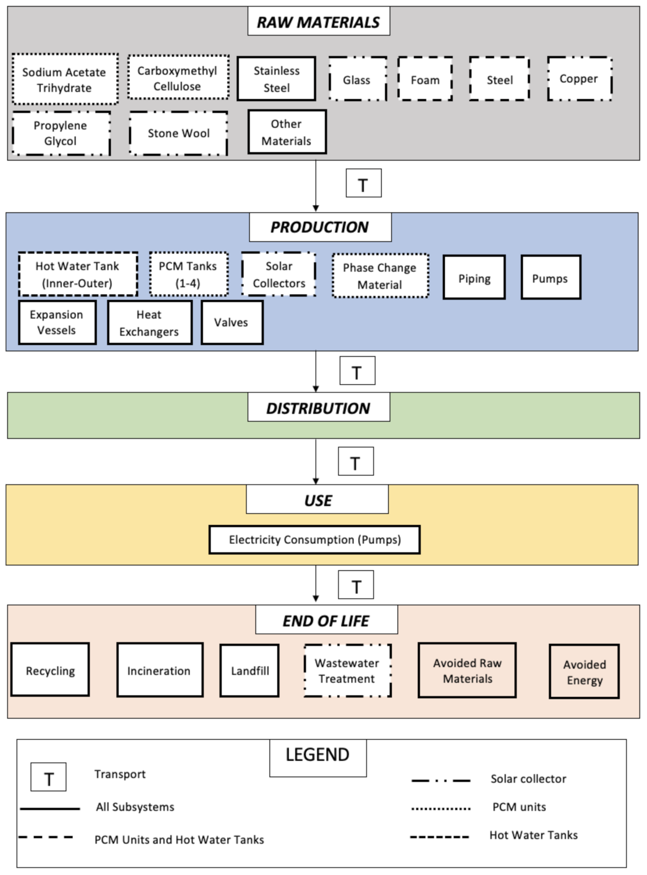
2.1. Goal and Scope
- Production of materials:
- ∘
- Phase change material mixture: SAT (which is the PCM) and Carboxymethyl Cellulose (CMC, thickening agent);
- ∘
- Evacuated tube solar collector, which includes glass, copper, propylene glycol, and stone wool;
- ∘
- Water and PCM storage tanks, made of foam and steel;
- ∘
- Stainless steel (used in the hot water tank, the PCM storage tanks, heat exchanger, and pumps)
- ∘
- Other materials: rubber (used in solar collectors), butyl acrylate (used in expansion vessels) and cast iron, aluminium, and polyvinylchloride (all used in pumps).
- Manufacturing of:
- ∘
- Hot water tanks, PCM tanks, solar collectors, PCM, piping, pumps, expansion vessels, heat exchangers, valves, stratifier, and the crystallization activation device. On the other hand, the hydronic circuits with the radiators and taps/showers were not included because they are not part of the S-LHTES-PCM system per se and are components that a typical UK household already has.
- Use:
- ∘
- Electricity consumption of the pumps to circulate the water.
- End of life:
- ∘
- Disposal of components after they have reached their life expectancy.
- Distribution:
- ∘
- Transport of all the components from production to the household in the UK and to the treatment plant at the end of life.
2.2. Inventory Data
2.2.1. Raw Materials
2.2.2. Production
2.2.3. Use
2.2.4. Transport
2.2.5. End of Life
2.3. Sensitivity Analysis
2.4. Comparison with Current Sources of Heat in the UK
2.5. Impact Assessment
3. Results
3.1. Life Cycle Assessment
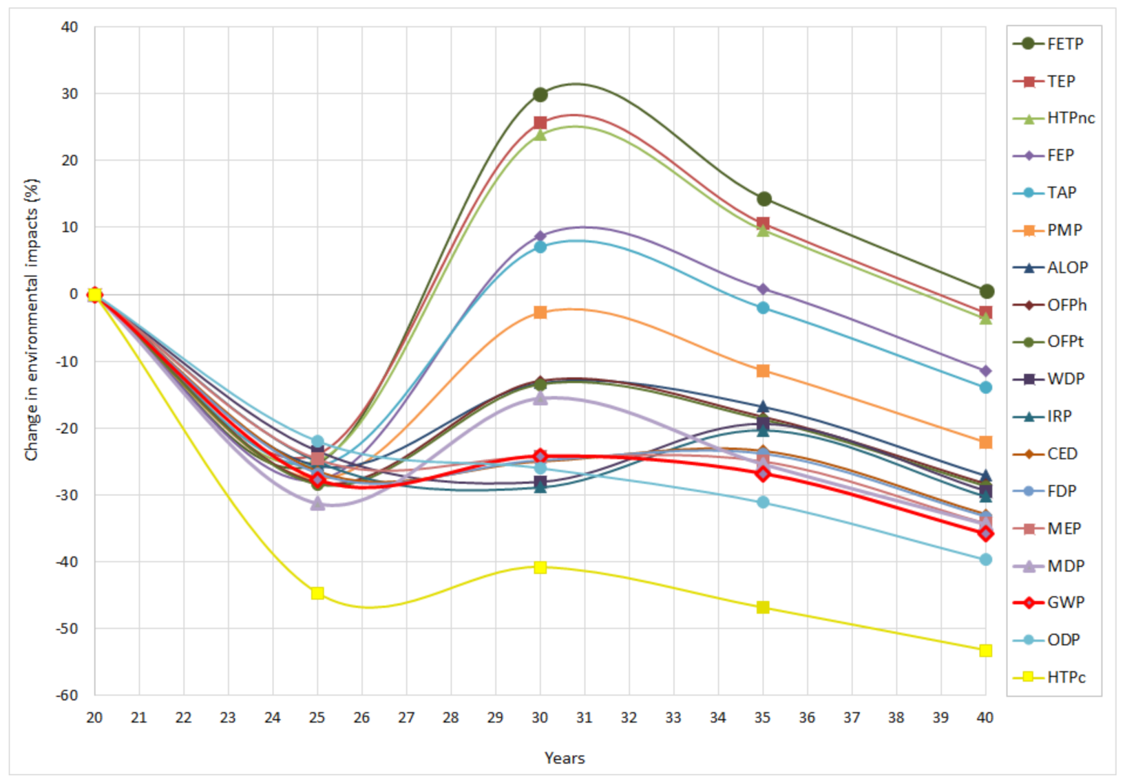
3.2. Sensitivity Analysis: Lifetime Extension
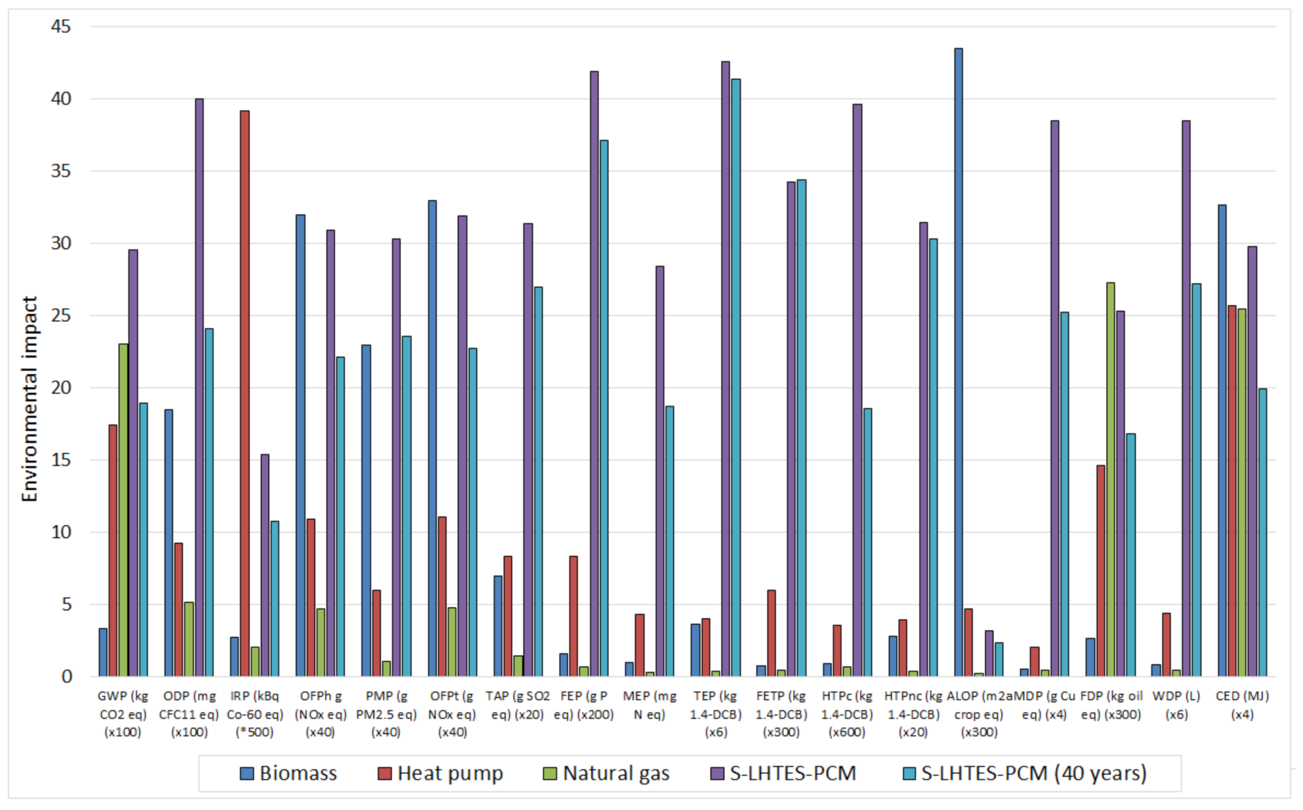
3.3. Comparison with Natural Gas, Biomass and Heat Pumps
4. Conclusions
Supplementary Materials
Author Contributions
Funding
Institutional Review Board Statement
Informed Consent Statement
Data Availability Statement
Acknowledgments
Conflicts of Interest
Acronyms
| ABS | Acrylonitrile butadiene styrene |
| ALOP | Agricultural land occupation potential |
| BIPV | Building integrated photovoltaic |
| BIPVT | Building integrated photovoltaic/thermal |
| CED | Cumulative energy demand |
| CMC | Carboxymethyl cellulose |
| EPDM | Ethylene propylene diene monomer |
| FDP | Fossil depletion potential |
| FEP | Freshwater eutrophication potential |
| FETP | Freshwater ecotoxicity potential |
| FU | Functional unit |
| GWP | Global warming potential |
| HTPc | Human carcinogenic toxicity potential |
| HTPnc | Human non-carcinogenic toxicity potential |
| IRP | Ionizing radiation potential |
| LCA | Life cycle assessment |
| LHTES | Latent heat thermal energy storage |
| MDI | Methylene diphenyl diisocyanate |
| MDP | Mineral depletion potential |
| MEP | Marine eutrophication potential |
| ODP | Stratospheric ozone depletion potential |
| OFPh | Ozone formation potential human health |
| OFPt | Ozone formation potential terrestrial ecosystems |
| PCM | Phase change material |
| PMP | Fine particulate matter formation potential |
| SAT | Sodium acetate trihydrate |
| SHS | Sensible heat storage |
| S-LHTES | Solar power latent heat thermal energy storage |
| S-LHTES-PCM | Solar power latent heat thermal energy storage with phase change material |
| TAP | Terrestrial acidification potential |
| TEP | Terrestrial ecotoxicity potential |
| TES | Thermal energy storage |
| THS | Thermochemical heat storage |
| WDP | Water consumption potential |
References
- United Nations Climate Change the Paris Agreement. Available online: https://unfccc.int/process-and-meetings/the-paris-agreement/the-paris-agreement (accessed on 10 June 2021).
- National Grid Balancing the Grid. Available online: https://www.nationalgrid.com/britain-hits-historic-clean-energy-milestone-zero-carbon-electricity-outstrips-fossil-fuels-2019 (accessed on 28 July 2021).
- Department for Business Energy & Strategy UK Becomes First Major Economy to Pass Net Zero Emissions Law. Available online: https://www.gov.uk/government/news/uk-becomes-first-major-economy-to-pass-net-zero-emissions-law (accessed on 1 August 2021).
- The Parliamentary Office of Science and Technology Carbon Footprint of Heat Generation. Available online: http://researchbriefings.files.parliament.uk/documents/POST-PN-0523/POST-PN-0523.pdf (accessed on 28 May 2021).
- Committee on Climate Change Reducing UK Emissions. Available online: https://www.theccc.org.uk/publication/reducing-uk-emissions-2020-progress-report-to-parliament/ (accessed on 27 May 2021).
- Cabeza, L.F.; Martorell, I.; Miró, L.; Fernández, A.I.; Barreneche, C. Introduction to thermal energy storage (TES) systems. In Advances in Thermal Energy Storage Systems; Woodhead Publishing Limited: Cambridge, UK, 2015; pp. 1–28. [Google Scholar] [CrossRef]
- Zhao, B.C.; Li, T.X.; Gao, J.C.; Wang, R.Z. Latent heat thermal storage using salt hydrates for distributed building heating: A multi-level scale-up research. Renew. Sustain. Energy Rev. 2020, 121. [Google Scholar] [CrossRef]
- Kerskes, H. Thermochemical Energy Storage. In Storing Energy: With Special Reference to Renewable Energy Sources; Elsevier Inc: Amsterdam, The Netherlands, 2016; pp. 345–372. [Google Scholar] [CrossRef]
- Wu, S. Heat energy storage and cooling in buildings. In Materials for Energy Efficiency and Thermal Comfort in Buildings; Woodhead Publishing: New York, NY, USA, 2010; pp. 101–126. [Google Scholar] [CrossRef]
- Englmair, G.; Moser, C.; Furbo, S.; Dannemand, M.; Fan, J. Design and functionality of a segmented heat-storage prototype utilizing stable supercooling of sodium acetate trihydrate in a solar heating system. Appl. Energy 2018, 221, 522–534. [Google Scholar] [CrossRef] [Green Version]
- Dannemand, M.; Schultz, J.M.; Johansen, J.B.; Furbo, S. Long term thermal energy storage with stable supercooled sodium acetate trihydrate. Appl. Therm. Eng. 2015, 91, 671–678. [Google Scholar] [CrossRef] [Green Version]
- Cabeza, L.F. Advances in thermal energy storage systems: Methods and applications. In Advances in Thermal Energy Storage Systems, 2nd ed.; Woodhead Publishing Limited: Cambridge, UK, 2021; pp. 37–54. [Google Scholar] [CrossRef]
- Jungbluth, N. Life Cycle Inventory of Sodium Acetate and Expanded Graphite. Available online: https://www.osti.gov/etdeweb/servlets/purl/22119615 (accessed on 18 June 2021).
- Noël, J.A.; Allred, P.M.; White, M.A. Life cycle assessment of two biologically produced phase change materials and their related products. Int. J. Life Cycle Assess. 2015, 20, 367–376. [Google Scholar] [CrossRef]
- Lamnatou, C.; Notton, G.; Chemisana, D.; Cristofari, C. Storage systems for building-integrated photovoltaic (BIPV) and building-integrated photovoltaic/thermal (BIPVT) installations: Environmental profile and other aspects. Sci. Total Environ. 2020, 699, 134269. [Google Scholar] [CrossRef] [PubMed]
- ISO. ISO 14044:2006 Environmental Management–Life Cycle Assessment–Requirements and Guidelines. Available online: https://www.iso.org/standard/38498.html (accessed on 1 September 2021).
- ISO. ISO 14040:2006 Environmental Management–Life Cycle Assessment–Principles and Framework. Available online: https://www.iso.org/standard/37456.html (accessed on 1 September 2021).
- Oró, E.; Gil, A.; de Gracia, A.; Boer, D.; Cabeza, L.F. Comparative life cycle assessment of thermal energy storage systems for solar power plants. Renew. Energy 2012, 44, 166–173. [Google Scholar] [CrossRef]
- Englmair, G.; Moser, C.; Schranzhofer, H.; Fan, J.; Furbo, S. A solar combi-system utilizing stable supercooling of sodium acetate trihydrate for heat storage: Numerical performance investigation. Appl. Energy 2019, 242, 1108–1120. [Google Scholar] [CrossRef]
- Zhang, H. Heat-insulating Materials and Sound-absorbing Materials. Build. Mater. Civ. Eng. 2011, 316–423. [Google Scholar] [CrossRef]
- Kingspan Solar Thermomax HP400 New Slimline Design Heat Pipe Vacuum Tube Solar Collector. Available online: https://www.midlandheating.ie/docs/solar-1-kingspan.pdf (accessed on 7 July 2021).
- Armstrong Efficient Heat Transfer in a Compact Design. Available online: https://docplayer.net/27537357-Phe-plate-heat-exchangers.html (accessed on 15 July 2020).
- Tyfo TYCOR-LS. Available online: https://www.plumbase.co.uk/link/1/h030224_31294_t.pdf (accessed on 15 August 2021).
- Ecoinvent Center the Ecoinvent Database. Available online: https://www.ecoinvent.org/database/database.html (accessed on 6 June 2021).
- Federal LCA Commons USLCI Database. Available online: https://www.lcacommons.gov/lca-collaboration/search/page=1&group=National_Renewable_Energy_Laboratory (accessed on 7 June 2021).
- De Falco, M.; Capocelli, M.; Losito, G.; Piemonte, V. LCA perspective to assess the environmental impact of a novel PCM-based cold storage unit for the civil air conditioning. J. Clean. Prod. 2017, 165, 697–704. [Google Scholar] [CrossRef]
- Adolfsson, M.; Rashid, S. Life Cycle Assessment and Life Cycle Cost of Heat Exchangers A Case for Inter Terminals Sweden AB Located in Port of Gothenburg. Master’s Thesis, Chalmers University of Technology, Gothenburg, Sweden, 2016. [Google Scholar]
- ACV Smart 600-Tank in Tank. Available online: https://www.acv.com/belgie/customer/product/06619301-393/smart-600 (accessed on 12 July 2020).
- Complete Pumpsupplies Flamco Flexcon Premium 50 Litre Expansion Vessel. Available online: https://www.completepumpsupplies.co.uk/flamco-flexcon-top-50-litre-expansion-vessel (accessed on 16 June 2021).
- StoneMark Construction Management Pipes Are Not a Lifetime Component. Available online: https://stonemarkcm.com/blog/pipes-not-lifetime-component/ (accessed on 5 August 2021).
- EPA Table 1: Typical Equipment Life Expectancy. Available online: https://www.waterboards.ca.gov/drinking_water/certlic/drinkingwater/documents/tmfplanningandreports/Typical_life.pdf (accessed on 21 July 2021).
- Englmair, G.; Kong, W.; Brinkø Berg, J.; Furbo, S.; Fan, J. Demonstration of a solar combi-system utilizing stable supercooling of sodium acetate trihydrate for heat storage. Appl. Therm. Eng. 2020, 166, 114647. [Google Scholar] [CrossRef]
- Masteel Applications of Grade 304 Stainless Steel. Available online: https://masteel.co.uk/type-304-stainless-steel/ (accessed on 2 July 2021).
- Shah, K.N.; Varandani, N.S.; Panchani, M. Life Cycle Assessment of Household Water Tanks—A Study of LLDPE, Mild Steel and RCC Tanks. J. Environ. Prot. 2016, 7, 760–769. [Google Scholar] [CrossRef] [Green Version]
- Plastics Europe. Plastics—The Facts 2019 an Analysis of European Plastics Production, Demand and Waste Data. Available online: https://www.plasticseurope.org/en/resources/market-data (accessed on 2 July 2021).
- Bowyer, J.; Bratkovich, S.; Fernholz, K.; Frank, M.; Groot, H.; Howe, J.; Pepke, E. Understanding Steel Recovery and Recycling Rates and Limitations to Recycling; Dovetail Partners Inc.: Minneapolis, MN, USA, 2015; pp. 1–12. [Google Scholar]
- Copper Alliance A Global View of Production and Trade. Available online: https://sustainablecopper.org/global-pathways/ (accessed on 15 August 2021).
- OECD. OECD.stat. Available online: https://stats.oecd.org/# (accessed on 28 July 2021).
- Recovery Recycling Worldwide Glass Recycling-Current Market Trends. Available online: https://www.recovery-worldwide.com/en/artikel/glass-recycling-current-market-trends_3248774.html (accessed on 20 June 2021).
- Aste, N.; Groppi, F.; del Pero, C. The first installation under the Italian PV Rooftop Programme: A performance analysis referred to five years of operation. In Proceedings of the 2007 International Conference on Clean Electrical Power, Capri, Italy, 21–23 May; IEEE: Milan, Italy, 2007; pp. 360–365. [Google Scholar]
- Bergsma, G.; Sevenster, M. End-of-Life Best Approach for Allocating Recycling Benefits in LCAs of Metal Packaging; CE Delft: Delft, The Netherlands, 2013; p. 25. [Google Scholar]
- Gallego-Schmid, A.; Chen, H.-M.; Sharmina, M.; Mendoza, J.M.F. Links between circular economy and climate change mitigation in the built environment. J. Clean. Prod. 2020, 260, 121115. [Google Scholar] [CrossRef]
- Heyes, G.; Sharmina, M.; Mendoza, J.M.F.; Gallego-Schmid, A.; Azapagic, A. Developing and implementing circular economy business models in service-oriented technology companies. J. Clean. Prod. 2018, 177, 621–632. [Google Scholar] [CrossRef]
- Mendoza, J.M.F.; Sharmina, M.; Gallego-Schmid, A.; Heyes, G.; Azapagic, A. Integrating Backcasting and Eco-Design for the Circular Economy: The BECE Framework. J. Ind. Ecol. 2017, 21, 526–544. [Google Scholar] [CrossRef] [Green Version]
- Sansom, R. Decarbonising Low Grade Heat for Low Carbon Future. PhD. Thesis, Imperial College London, London, UK, 2014. [Google Scholar]
- Huijbregts, M.A.J.; Steinmann, Z.J.N.; Elshout, P.M.F.; Stam, G.; Verones, F.; Vieira, M.; Zijp, M.; Hollander, A.; van Zelm, R. ReCiPe2016: A harmonised life cycle impact assessment method at midpoint and endpoint level. Int. J. Life Cycle Assess. 2017, 22, 138–147. [Google Scholar] [CrossRef]
- Welfle, A.; Thornley, P.; Röder, M. A review of the role of bioenergy modelling in renewable energy research & policy development. Biomass Bioenergy 2020, 136. [Google Scholar] [CrossRef]
- Welfle, A.; Gilbert, P.; Thornley, P. Increasing biomass resource availability through supply chain analysis. Biomass Bioenergy 2014, 70, 249–266. [Google Scholar] [CrossRef]
- Strbac, G.; Pudjianto, D.; Sansom, R.; Djapic, P.; Ameli, H.; Shah, N.; Brandon, N.; Hawkes, A. Analysis of Alternative UK Heat Decarbonisation Pathways. Available online: https://www.theccc.org.uk/wp-content/uploads/2018/06/Imperial-College-2018-Analysis-of-Alternative-UK-Heat-Decarbonisation-Pathways.pdf (accessed on 29 July 2021).


| Component | Lifetime | Reference |
|---|---|---|
| Phase change material | 10 years | [26] |
| Heat exchanger | 30 years | [27] |
| Inner tank | 25 years | [28] |
| Solar collector | 20 years | [21] |
| Heat transfer fluid | 3 years | [23] |
| Water pump | 5 years | [24] |
| Expansion vessels | 15 years | [29] |
| Piping | Copper 40 years | [30] |
| Steel 40 years | ||
| Valves | 40 years | [31] |
| Life Cycle Stage | S-LHTES-PCM | Reference |
|---|---|---|
| Raw materials | ||
| Sodium acetate trihydrate (PCM) (g) | 41.8 | [10,11,32] |
| Carboxymethyl cellulose (PCM) (g) | 0.4 | |
| Stainless steel (hot water tank, PCM tanks, heat exchanger, solar collector, and pumps) (g) | 12.7 | [21,22,24,28,32,33] |
| Glass tube (solar collector) (g) | 7.6 | [21,24] |
| Foam (hot water tank, PCM-tanks) (g) | 5.8 | [20] |
| Carbon steel (hot water tank, piping, heat exchanger, expansion vessel, and valves) (g) | 19.6 | [22,24,28,32] |
| Copper (solar collector, piping, and pumps) (g) | 1.5 | [21,24] |
| Propylene glycol (solar collector) (g) | 2 | [23] |
| Stone wool (solar collector) (g) | 1.1 | [21,24] |
| Other materials (solar collector, expansion vessel, and pumps) (g) a | 0.9 | [21,24] |
| Production | ||
| Electricity (all elements) (kJ) | 99.7 | [13,24,34] |
| Heat (all elements) (kJ) | 29 | |
| Transport | ||
| Freight lorry (all elements) (kg·km) | 2.1 | [24] |
| Freight train (all elements) (kg·km) | 0.02 | |
| Use | ||
| Electricity Consumption (kJ) | 12.9 | [32] |
| End of Life | ||
| Recycling: Plastics (g) | 1.8 | [35] |
| Recycling: Metals (g) | 27 | [36,37] |
| Incineration with energy recovery: Plastics (g) | 3.4 | [35] |
| Incineration with energy recovery: PCM (g) | 42.2 | [13] |
| Incineration with energy recovery: Stone wool (g) | 0.7 | [38] |
| Landfilling: Plastics (g) | 1.3 | [35] |
| Landfilling: Glass (g) | 7.6 | [39] |
| Landfilling: Metals (g) | 5.1 | [36,37] |
| Landfilling: Stone wool (g) | 0.4 | [38] |
| Wastewater treatment (l) | 0.005 | [24] |
Publisher’s Note: MDPI stays neutral with regard to jurisdictional claims in published maps and institutional affiliations. |
© 2021 by the authors. Licensee MDPI, Basel, Switzerland. This article is an open access article distributed under the terms and conditions of the Creative Commons Attribution (CC BY) license (https://creativecommons.org/licenses/by/4.0/).
Share and Cite
Chocontá Bernal, D.; Muñoz, E.; Manente, G.; Sciacovelli, A.; Ameli, H.; Gallego-Schmid, A. Environmental Assessment of Latent Heat Thermal Energy Storage Technology System with Phase Change Material for Domestic Heating Applications. Sustainability 2021, 13, 11265. https://doi.org/10.3390/su132011265
Chocontá Bernal D, Muñoz E, Manente G, Sciacovelli A, Ameli H, Gallego-Schmid A. Environmental Assessment of Latent Heat Thermal Energy Storage Technology System with Phase Change Material for Domestic Heating Applications. Sustainability. 2021; 13(20):11265. https://doi.org/10.3390/su132011265
Chicago/Turabian StyleChocontá Bernal, Daniel, Edmundo Muñoz, Giovanni Manente, Adriano Sciacovelli, Hossein Ameli, and Alejandro Gallego-Schmid. 2021. "Environmental Assessment of Latent Heat Thermal Energy Storage Technology System with Phase Change Material for Domestic Heating Applications" Sustainability 13, no. 20: 11265. https://doi.org/10.3390/su132011265
APA StyleChocontá Bernal, D., Muñoz, E., Manente, G., Sciacovelli, A., Ameli, H., & Gallego-Schmid, A. (2021). Environmental Assessment of Latent Heat Thermal Energy Storage Technology System with Phase Change Material for Domestic Heating Applications. Sustainability, 13(20), 11265. https://doi.org/10.3390/su132011265