Abstract
A heat treatment is effective for reducing the residual stress of the welded structures. A post-weld heat treatment (PWHT) requires a large heating apparatus (furnace). It requires a high energy, a long time, and a high cost. For examining the possibility of cost and energy saving in PWHT work, an economical and mechanical investigation of the local PWHT to stiffened plate members in steel bridges was conducted. The expense of apparatus for the furnace PWHT was 1.5 times higher than that of local PWHT by sheet-type ceramic heaters. When the number of heater units was reduced and were repeatedly used, the expense for the apparatus became lower. However, it took longer to complete the heat treatment than with the furnace PWHT or the local PWHT with full heater units. The thermal elastic-plastic finite element (FE) analysis examined the effect of local PWHT. The tendency of the stress distribution after the local PWHT differed from the welding residual stress or the stress after the furnace PWHT because of the temperature difference between the heated and the non-heated parts of the local PWHT. However, the effect of residual stress relief by the local PWHT could be almost the same as that of the furnace PWHT.
1. Introduction
Stiffened steel plates are generally used in steel bridge structural members, such as box girders, piers, and decks [,,]. The stiffeners are welded to the base plates in order to ensure high bending stiffness so that the relatively thin base plates are available and a light weight is achieved in the plates. When the stiffeners are welded to the base plates, the welding deformation and residual stress are inevitably generated. The high tensile residual welding stress generated near the weld metal decreases the fatigue performance of welded joints []. The compressive residual stress generated away from the welded part for balancing the tensile residual stress decreases the buckling strength of the plates [].
For improving residual welding stress states, several countermeasures have been developed [,]. As for reducing the tensile residual stress to improve the fatigue strength of the welded part, the peening by shot, hammer (high-frequency mechanical impact: HFMI), and ultrasonic impact is effective [,,]. The peening makes the deformation at the weld toe locally. The local deformation is then constrained by the surrounding parts. As a result, the plastic deformation and the compressive stress are generated at the weld toe. It is well known that the compressive stress applied by the peening enhances the fatigue strength of the weld toe. Although these countermeasures are useful and reasonable, the treatment area is limited to the area locally around the welded part. It may take a long time to apply these local methods to all welded parts in a large structure. One of the most common procedures for relieving residual stress in a whole structure is post-weld heat treatment (PWHT) []. PWHT is known as stress relief (SR) annealing for reducing residual stress by using creep strain. Previous studies show the effectiveness of PWHT for reducing the welding residual stress in several steel structures. Huang et al. examined the effect of PWHT on the residual stress and the mechanical properties of electron beam welded SAE4130 steel plates []. Paradowska et al. applied PWHT to welded tubular joints in order to improve the fatigue life by reducing hardness and residual stress []. They estimated that the residual stress relief might contribute to improvement in the fatigue life, in which the fatigue life of the joints might be increased by 2.3 times to 12.7 times from the case without PWHT. Aung et al. investigated the effectiveness of PWHT for improving the fatigue strength of patch-plate welded joints by mild steel []. They experimentally showed that the fatigue life of the patch-plate welded joints with PWHT was increased by 2.0 to 10.0 times from the case without PWHT, although the improvement effect depended on the fatigue loading conditions. In any case, it can be said that the life of the welded structures is improved by PWHT. PWHT requires a higher cost than the production without PWHT, however, it contributes to the service-life extension of the products. Therefore, the application of PWHT should be considered by seeking a balance between the initial cost increase and the maintenance cost decrease.
In PWHT, the welded member is kept in a thermostatic chamber, such as a furnace. The relatively low temperature below the A1 transformation point, which is around 723 °C in low carbon steel, is used as the soaking temperature. The thickness of the member influences the heating rate, soaking duration, and cooling rate. A slow heating/cooling rates and longer soaking time are required for the PWHT of a thick welded member. A giant furnace is also required. Such a large furnace is naturally expensive and not easily installed in the factory due to the limitations of size and the existing processing line.
To mitigate these difficulties, a method of local PWHT is examined in this study. The local PWHT means that the thermal history of stress relief annealing is applied to the welded parts and around them locally. The method of the local PWHT is also specified, as well as the furnace PWHT []. One of the authors of this study has conducted continuous studies about applying local PWHT to steel bridge members. It has been shown that, by using sheet-type ceramic heaters, local PWHT could reduce the residual welding stress and improve the fatigue strength and the load-carrying capacity of welded members [,].
This study investigates the primary applicability of the local PWHT to steel bridge members from economical and mechanical viewpoints. The target welded structural member is a stiffened plate with several welded lines, as mentioned above. The relatively thin steel plates might be suitable for the local PWHT with low heat energy. However, the heat input to thin steel plates might generate the deformation. A simple estimation and comparison of the cost for the furnace PWHT and the local PWHT, based on actual work information, was conducted. Furthermore, numerical simulation by finite element (FE) analysis for comparing the effects of residual stress relief by the furnace PWHT and the local PWHT was carried out.
2. Structural Model for Investigation
Figure 1 shows the structural model to be examined in this study. A steel plate with 5 stiffeners is assumed as a part or section of a box girder or plate deck. The base plate has a thickness of 12 mm. The dimensions of the stiffeners are 230 mm high and 11 mm thick. These are the typical dimensions of steel bridge members. The stiffeners are welded to the base plate by fillet welding from both sides. The leg length of the weld bead is assumed to be 6 mm. The length of the stiffened plate is 10 m. The number of stiffeners is set as five, an amount which takes into consideration the limitation of automatic welding equipment. Generally, the parallel welding-torch number of automatic welding equipment used in bridge fabrication companies is ten. This enables the welding of five stiffeners using fillet welding from both sides at once. The length of the stiffened plate is set as 10 m, which takes into consideration the limitation for dimensions that can be transported by truck.
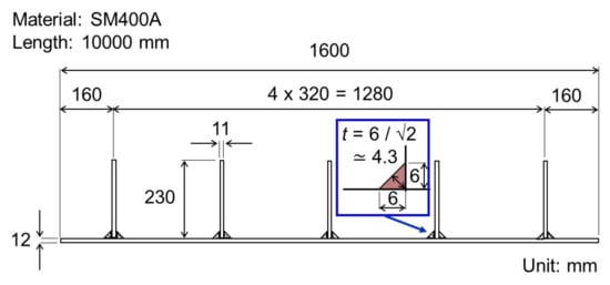
Figure 1.
Stiffened plate model.
The material used for the base plate and stiffeners is SM400A, specified by JIS G 3106 [] as one of the most popular mild steels used for structural bridge members. Table 1 shows the specifications for the chemical compositions and mechanical properties.

Table 1.
Specifications for SM400A (thickness is under 16 mm).
3. PWHT Conditions and Heating Apparatus
3.1. PWHT Conditions
Table 2 shows the PWHT conditions for mild steels specified by JIS Z 3700 []. The throat thickness of fillet welds determines the heating rate, cooling rate, and soaking duration. The soaking temperature is set as 595 °C for mild steel. These conditions are applied when the temperature exceeds 425 °C because the creep strain of mild steel might occur over this temperature range []. If the leg length of a fillet weld is 6 mm, as shown in Figure 1, the throat thickness, t will be approximately 4.3 mm, which is smaller than 25 mm. Therefore, the maximum heating rate of 220 °C/h and the cooling rate of 280 °C/h can be applied. In the same way, the minimum soaking time of 1/4 h (25 min) can be applied. Figure 2a shows the applied temperature history for PWHT of the target stiffened plate. The temperature control is not required under the range of 425 °C. However, the uniform heating and cooling rates are assumed to be applied because the controllability and the capacity of the heat source are unknown for the higher heating and cooling rates than the specified value.
Table 2.
PWHT conditions specified by JIS Z 3700 (temperature is over 425 °C).
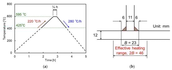
Figure 2.
(a) Temperature history for PWHT; (b) Effective heating range for local PWHT.
In the case of the furnace PWHT, the temperature history is applied to the welded member to be treated in a furnace. Therefore, the temperature is expected to be uniform throughout the member. On the other hand, the local PWHT allows for heating the limited part around the welds. The heating range, on the other hand, must be sufficient. The heating range should be at least twice the thickness of the weld on each side from the maximum width of the weld, B. As shown in Figure 2b, the effective heating range, 2B will be over 46 mm. In this range, the temperature difference should be smaller than 150 °C in the heating stage and 85 °C in the soaking stage.
3.2. Heating Apparatus
3.2.1. Furnace for the PWHT
The available heating apparatus is assumed to achieve the furnace PWHT or local PWHT of the target stiffened plate. A large furnace by a gas flame or electric heating, as shown in Figure 3a, is generally used for the furnace PWHT. Based on the actual work experiences of heat treatment experts, the inner side of the furnace should be 11 m long, 3 m wide, and 1 m deep for the target member. The capacity of the heat energy should be 200 kW to 300 kW. Accordingly, the construction price of the furnace will be approximately 30,000,000 JPY. Appling the rate to Euro at July 2021 (130.80 JPY/EUR), it is 229,358 EUR.
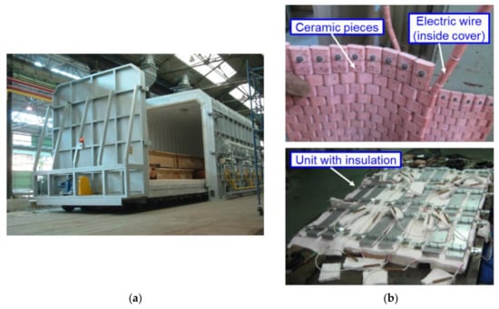
Figure 3.
(a) Furnace for PWHT; (b) Sheet-type ceramic heater.
3.2.2. Sheet-Type Ceramic Heater for Local PWHT
A sheet-type ceramic heater, as shown in Figure 3b is effective for local PWHT. This heater is assembled with the electrically heated wire and ceramic pieces surrounding it. The shape and dimension of the heater can be changed flexibly by arranging the length of electrically heated wire and the number of ceramic pieces. Previously programmed temperature history data automatically control the heat input. The electric power is changed so that the monitored temperature by thermocouples on the target member follows the programmed history. The heater is surrounded by a thermal insulation material, such as glass fibers. The thermal insulation is applied to the heater and the other part of the target member to suppress heat radiation. The combined unit of the heater and thermal insulation is used for the local PWHT. The authors investigated the applicability of this sheet-type ceramic heater for PWHT of welded joint specimens such as trapezoidal stiffener welded on a plate and box-section joints [,]. The residual stress reduction by PWHT could be confirmed in all of the specimen types.
When assembling one heater unit, including the heater, the thermal insulation, and the controller, the cost depends on the size of the heater unit. Based on the actual work experiences of heat treatment experts, the cost of a heater unit of 75 to 100 mm wide and 11 m long will be 4,000,000 JPY. Appling the rate to the Euro at July 2021 (130.80 JPY/EUR), it is 30,581 EUR.
4. Cost and Time Estimation of PWHT
Here, the cost and time by the furnace PWHT and the local PWHT are estimated and compared with each other. The furnace PWHT simply requires the cost of the apparatus as 30,000,000 JPY (229,358 EUR). The time for PWHT is around 5 h, as shown in Figure 2a. On the other hand, the local PWHT has several patterns depending on the number of the heater unit. When the five welded parts around the stiffeners are heated at one time by using five heater units, the time for PWHT will be equal to that of the furnace PWHT. If three heater units are applied to the three welded parts in the first cycle, the remaining two welded parts might be heated by two heater units after finishing the first cycle. Three heater units make it possible to perform the local PWHT with two cycles (3 units × 1 cycle and 2 units × 1 cycle). In the same way, two heater units require three cycles (2 units × 2 cycles and 1 unit × 1 cycle) for PWHT. It might take 25 h (5 h × 5 cycles) if only one heater unit is repeatedly used on the five welded parts, one by one.
Figure 4 shows the relationship between the estimated cost and PWHT time. The costs were normalized by the expense of the furnace for the furnace PWHT. The local PWHT by five heater units requires a lower cost than the furnace PWHT. The costs can be reduced by saving the number of heater units. However, a longer PWHT time will be naturally required. It can be said that the number of heater units should be decided by considering the trade-off relationship between the cost and time.
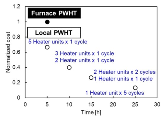
Figure 4.
Relationship between cost and time for the furnace PWHT and the local PWHT.
5. FE Analysis on Furnace PWHT and Local PWHT
5.1. FE Model
Here, a series of numerical simulations by FE analysis were conducted in order to investigate the influence of the local PWHT on the generation of additional deformation and the stress relief, compared to the furnace PWHT.
The FE model for the target stiffened plate construction is shown in Figure 5. A commercial FE analysis code Abaqus Ver. 6.14 was used in this study. The function of coupled temperature-displacement analysis was selected. Generally, three-dimensional solid elements are used for the welding simulation in order to model the geometry of the weld beads. Furthermore, the solid elements are necessary for dividing the mesh in the plate-thickness direction. However, the use of solid elements increases the number of the nodal points, which results in a longer computing time. To solve this kind of inconvenience, the authors proposed the use of 4-nodes shell elements for the welding simulation [,,]. In this proposed method, the heat input by welding was idealized to the concentrated heat flux into the integration points of the shell elements by considering the heat energy distribution caused by the groove shape and the weld-bead shape. The number of the nodal points could be less than that of the model with the solid elements. The results of the previous study showed that the computing time for the simulation of the thin-plate butt-welded joints and the T-shaped fillet-welded joints was shortened by over 90% compared to the case modeled by the solid elements. However, the accuracy of the simulation modeled by the shell elements was almost the same as the case modeled by the solid elements. For expecting this effectiveness, this study also adopted the 4-nodes shell elements for assembling the analysis model.
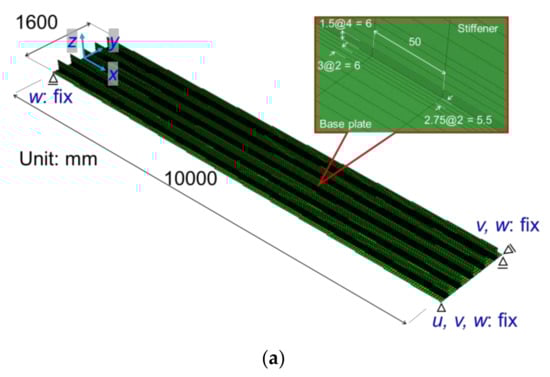
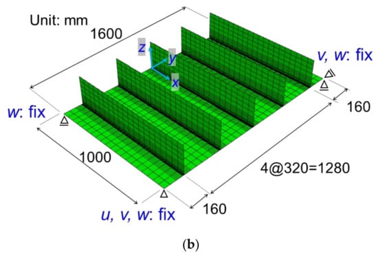
Figure 5.
(a) Long model for FE analysis; (b) Short model for FE analysis.
In this study, two types of analysis models were established. The extended model had a total length of 10 m (Figure 5a). The short model had a length of 1 m (Figure 5b).
Although the lengths of both models were different, the mesh divisions were the same. The mesh size in the welding (x) direction was regularly 50 mm. The connection part between the base plate and the stiffener was divided irregularly, in consideration of the imaginary shape of the weld bead, as described later. The short model was examined for saving the computing time compared to the extended model. The welding and PHWT on the long continuous structure, like the stiffened plate, might produce a uniform steady-state in the longitudinal direction. Therefore, the results obtained by the short model might coincide with that by the long model at the midspans of both models, where the influence of the edges of the models might be small.
Figure 6 shows the physical constants and mechanical properties used in the analysis. They are the temperature-dependent types referred to in previous researches [,,]. The stress-strain curve was modeled by the perfect elastic-plastic type. As for the hardening law, the movement of the yield surface was not considered. The welded components were given the same material characteristics as the base metal (SM400A).
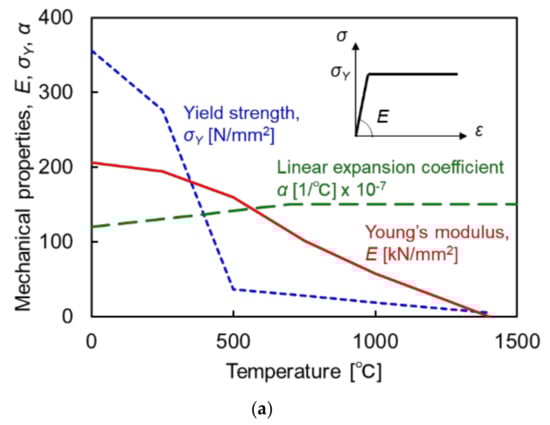
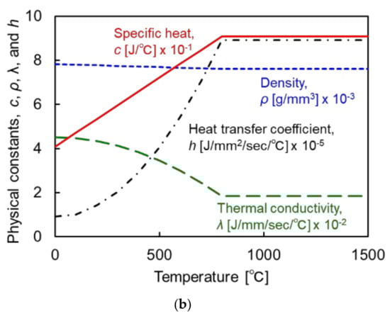
Figure 6.
(a) Mechanical properties; (b) Physical constants and heat transfer coefficient.
As a mechanical boundary condition, a rigid body displacement was fixed, as shown in Figure 5. The welding process and the PWHT process both had their thermal boundary conditions modified.
5.2. Simulation of the Welding Process
5.2.1. Analysis Conditions
Parallel welding by gas metal arc welding was assumed to be performed on both sides of all stiffeners simultaneously. The heat energy was calculated using Equation (1) based on the welding conditions. As shown in Figure 7, the heat energy was applied to the integration points of elements in stiffeners corresponding to the weld metal and the surface of the base plate connected to the weld metal [].
Here, Q is the heat input by welding [J/mm], V is the welding voltage [V], C is the welding current [A], and v is the welding speed [mm/s]. The welding conditions are referred to the actual fabrication information, such as the voltage, V of 31 [V] and the current, C of 280 [A], and the speed, v of 6.83 [mm/s]. The heat energy was applied to the welded parts consecutively as the moving heat source. The magnitudes of the concentrated heat flux, qi, and the surface heat flux, qs, were calculated by Equations (2) and (3). The heat energy in the weld bead of each heating step was Qv. This heat energy was allocated to the stiffener and the base plate by the ratio of the area of contact surfaces between the weld bead and the stiffener, As to that between the weld bead and base plate, Ab. In this case, these areas of As and Ab were the same and, therefore, half of the heat energy in the weld bead was applied to the stiffener and the base plate.
Here, qi is the concentrated heat flux at integration points in the weld bead part (J/s), is the surface heat flux at the contact surface between the weld bead and base plate (J/s/mm2), is the cross-sectional area of the contact surface between the weld bead and rib plate (mm2), Ab is the cross-sectional area of the contact surface between the weld bead and base plate (mm2), and is the number of integration points in the weld bead part. This concentrated heat flux and the surface heat flux were applied to the elements corresponding to the weld bead in the subsequent step manually.
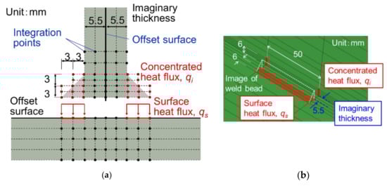
Figure 7.
(a) Heat input to weld metal parts; (b) Mesh division around the connection part.
In the welding process, the heat transfer to air from the whole model’s outer surface was considered to be the thermal boundary conditions.
5.2.2. Analysis Results
Figure 8a shows the welding temperature histories of the long and the short models at the bottom of the stiffened plates underneath the central stiffener. The time of the long model and the short model was arranged so that the points when the heat sources pass the central section in the longitudinal direction matches with each other.
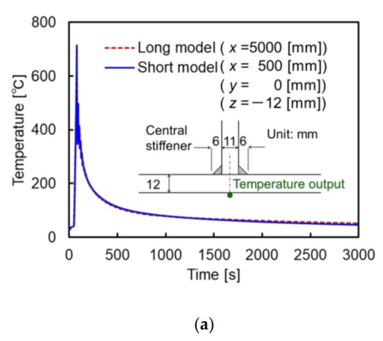
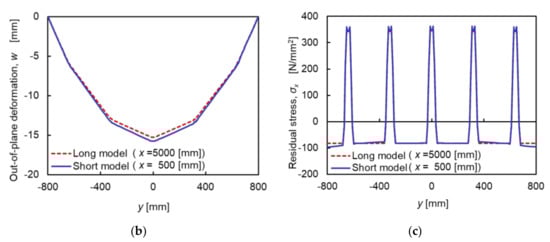
Figure 8.
(a) Welding temperature history; (b) Welding out-of-plane deformation; (c) Residual welding stress components in the x-direction.
Figure 8b shows the welding out-of-plane deformation of the long and the short models at the midspans. Figure 8c shows the residual stress components in the longitudinal direction of the long and the short models at the midspans. The temperature histories, the welding deformations, and the residual stresses of the long and short models were almost identical at the midspans because the uniform steady state might be created around there. This means that the shorter model is available for evaluating the features of deformation and stress states of a stiffened plate subjected to thermal histories. Therefore, the short model was only used for the following simulations, comparing the out-of-plane deformations and the residual stresses by the furnace PWHT with the local PWHT.
5.3. Simulation of PWHT Process
5.3.1. Analysis Conditions
The furnace PWHT and the local PWHT were assumed to be applied to the stiffened plate. In the case of the furnace PWHT, the thermal history (shown in Figure 3) was applied to all outer surfaces of the model after finishing the welding process. For the sake of considering the environment within the furnace, the heat transfer coefficient was set to zero. Figure 9 shows the positions of heaters and output positions of temperature for the local PWHT. Referring to the actual work experiences by heat treatment experts (Figure 9a), the width of the heater (100 mm) was assumed to satisfy the effective heating range of JIS Z 3700. For confirming the temperature histories around the heating area, the temperature was monitored at the six points shown in Figure 9b around the central stiffener. The same thermal history as the furnace PWHT was applied to only the surfaces corresponding to the position of the ceramic heater units. The heat transfer coefficient was set to zero at the surfaces, assuming that the whole stiffened plate is fully covered by the insulation material.
Figure 9.
(a) Heating area for local PWHT; (b) Output points of temperature during local PWHT.
The effect of annealing should be considered in the PWHT simulation. The previous studies modeled the annealing effect by considering the creep strain [,,,]. Although the simulation accuracy might be high by considering the creep strain as some mathematical formulas, a complicated calculation procedure is required. Therefore, the function of annealing, launched in Abaqus software, was used in this study. For easily considering the annealing effect, this function makes the accumulated plastic strain zero when the temperature reaches a specified value (annealing temperature). The annealing temperature was set as 425 °C in this analysis. For the use of the annealing function in Abaqus, the perfect elastic-plastic type should be adopted as the hardening law of the material. Because the isotropic and the perfect elastic-plastic hardening law was used in the analysis in this study, the accuracy of the obtained results should be discussed under their limited conditions. A more accurate simulation which considers the creep strain and kinematic hardening will be used in future work.
5.3.2. Analysis Results
Figure 10 shows the temperature histories during the local PWHT processes. The temperature of the furnace PWHT case naturally followed the designated history because the temperature at all nodal points of the model was forcibly controlled. The temperature of the local PWHT case followed the designated history only at the heating area (points A and B) as well as the furnace PWHT case. Because the base plate was thin, the temperature on the opposite surface of the heating region (points D and E) was almost identical. The temperature at the points which were 100 mm away from the center of the heating area (points C and F) was relatively lower; however, the maximum difference of temperature between points A and F was 51 °C.
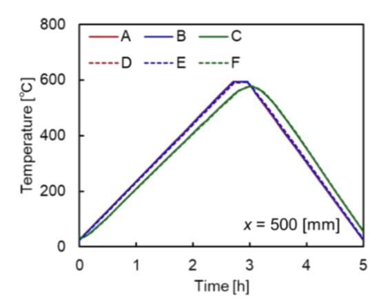
Figure 10.
Temperature histories during local PWHT.
The out-of-plane deformation before and after the PWHT is shown in Figure 11a. The out-of-plane deformations generated by the furnace PWHT and the local PWHT were small. Figure 11b shows the residual stress before and after the PWHT. Figure 12 shows the stress distributions of the furnace PWHT and the local PWHT. The figures show the residual stress in the welding (x) direction, σx of the upper surface of the base plate.
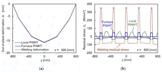
Figure 11.
(a) Out-of-plane deformations by the furnace PWHT and the local PWHT; (b) Residual stress distributions by the furnace PWHT and the local PWHT.
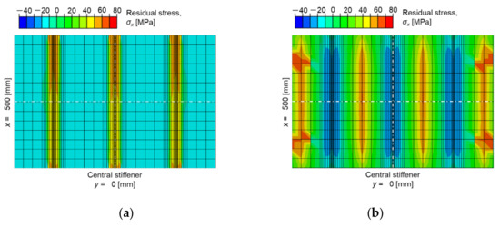
Figure 12.
(a) Residual stress distribution of base plate by furnace PWHT; (b) Residual stress distribution of base plate by local PWHT.
The residual welding stress could be released sufficiently by the furnace PWHT. The maximum tensile stress became 14% of the residual welding stress by the furnace PWHT. On the other hand, the tendency of stress distribution of local PWHT essentially changed. The stress around the stiffeners became compression from tension. The stress in the areas between stiffeners became tension from compression. The temperature in the non-heating area was lower than that in the heating area during the heating process. This temperature difference might cause a change in the tendency of stress distribution. However, it became higher than the heated area after the soaking time and during the cooling process. The maximum tensile stress became 17% of the residual welding stress by the local PWHT. Even though the tendency of stress distribution was not similar to that of the furnace PWHT, it could be said that the local PWHT obtained the effect of stress relief.
6. Conclusions
An economical and mechanical investigation of applying the local post-weld heat treatment (PWHT) to stiffened plate members in steel bridges was carried out. The obtained main results are as follows.
- (1)
- The costs required for the furnace PWHT and the local PWHT on the stiffened plate were estimated and compared. The expense of apparatus for the local PWHT assembled by sheet-type ceramic heaters was 67% of that for the furnace PWHT.
- (2)
- The cost and efficiency of local PWHT depended on the number of heater units. When the number of heater units was reduced and the heater units were repeatedly used, the expense for apparatus became lower. However, it took longer than the furnace PWHT or the local PWHT with complete heater units.
- (3)
- The thermal elastic-plastic finite element (FE) analysis was used to investigate the influence of local PWHT. The PWHT’s overall and local out-of-plane deformation was minimal. The furnace PWHT could reduce the residual welding stress sufficiently. The maximum tensile stress became 14% of the residual welding stress by the furnace PWHT.
- (4)
- The tendency of stress distribution of the local PWHT was different from that of the furnace PWHT. The stress around the stiffeners became compressed from tension. The stress in the areas between stiffeners became tense from compression. The temperature in the non-heating area was lower than that in the heating area during the heating process. However, it became higher than the heated area after the soaking time and during the cooling process. This temperature difference might cause a change in the tendency of stress distribution.
- (5)
- Even though the tendency of stress distribution was not similar to that of the furnace PWHT, the maximum tensile stress became 17% of the residual welding stress by the local PWHT. It could be said that the effect of stress relief was obtained by the local PWHT.
Naturally, PWHT requires a higher cost than the production without PWHT, however, it contributes to the service-life extension of the products. Therefore, the application of PWHT should be considered by the balance between the initial cost increase and the maintenance cost decrease, which depends on the type, the design philosophy, and the maintenance procedure of the structures. The more accurate numerical simulation considering the creep strain and the kinematic hardening will be performed as future work. Such work should include the experimental verification for validating the numerical analysis model. The variations of the local PWHT procedures should then be examined for optimizing the relationship between the cost and the benefit. These results will help in considering the application of the local PWHT to the actual welded structures.
Author Contributions
Conceptualization, M.H. and K.J.; methodology, M.H.; software, S.N.; validation, S.N. and M.H.; investigation, M.H.; writing—original draft preparation, M.H.; writing—review and editing, K.J. All authors have read and agreed to the published version of the manuscript.
Funding
This research was funded by JSPS KAKENHI, grant number 19KK0366.
Institutional Review Board Statement
Not applicable.
Informed Consent Statement
Not applicable.
Data Availability Statement
Not applicable.
Acknowledgments
Toshimitsu Suzuki and Hideaki Konishi, belonging MM Bridge Co., Ltd. provided the information related to the fabrication process of steel bridge members. Keita Hiramatsu, CEO of JEMIX Co., Ltd. provided the information related to the cost for PWHT. The authors greatly appreciated their support.
Conflicts of Interest
The authors declare no conflict of interest.
References
- Usami, T.; Zheng, Y.; Ge, H.B. Recent research developments in stability and ductility of steel bridge structures General Report. J. Constr. Steel Res. 2000, 55, 183–209. [Google Scholar] [CrossRef]
- Kitada, T.; Yamaguchi, T.; Matsumura, M.; Okada, J.; Ono, K.; Ochi, N. New technologies of steel bridge in Japan. J. Constr. Steel Res. 2002, 58, 21–70. [Google Scholar] [CrossRef]
- Kitada, T. Considerations on recent trends in, and future prospects of, steel bridge construction in Japan. J. Constr. Steel Res. 2006, 62, 1192–1198. [Google Scholar] [CrossRef]
- Cui, C.; Zhang, Q.; Bao, Y.; Bu, Y.; Luo, Y. Fatigue life evaluation of welded joints in steel bridge considering residual stress. J. Constr. Steel Res. 2019, 153, 509–518. [Google Scholar] [CrossRef]
- James, M.N. Residual stress influence on structural reliability. Eng. Fail. Anal. 2011, 18, 1909–1920. [Google Scholar] [CrossRef]
- Cheng, X.; Fisher, J.W.; Prask, H.J.; Gnäupel-Herold, T.; Yen, B.T.; Roy, S. Residual stress modification by post-weld treatment and its beneficial effect on fatigue strength of welded structures. Int. J. Fatigue 2003, 25, 1259–1269. [Google Scholar] [CrossRef]
- Ooi, S.W.; Garnham, J.E.; Ramjaun, T.I. Review: Low transformation temperature weld wire for tensile residual stress reduction. Mater. Des. 2014, 56, 773–781. [Google Scholar] [CrossRef]
- Kobayashi, M.; Matsui, T.; Murakami, Y. Mechanism of creation of compressive residual stress by shot peening. Int. J. Fatigue 1998, 20, 351–357. [Google Scholar] [CrossRef]
- Yildirim, H.C.; Marquis, G.B. Overview of fatigue data for high frequency mechanical impact treated welded joints. Weld. World 2012, 56, 82–96. [Google Scholar] [CrossRef]
- Roy, S.; Fisher, J.W.; Yen, B.T. Fatigue resistance of welded details enhanced by ultrasonic impact treatment (UIT). Int. J. Fatigue 2003, 25, 1239–1247. [Google Scholar] [CrossRef]
- Abson, D.J.; Tkach, Y.; Hadley, I.; Wright, V.S.; Burdekin, F.M. A review of postweld heat treatment code exemptions. Weld. J. 2006, 85, 63–69. [Google Scholar]
- Huang, C.C.; Pan, Y.C.; Chuang, T.H. Effects of post-weld heat treatment on the residual stress and mechanical properties of electron beam welded SAE 4130 steel plates. J. Mater. Eng. Perform. 1997, 6, 61–68. [Google Scholar] [CrossRef]
- Paradowska, A.M.; Price, J.W.H.; Kerezsi, B.; Dayawansa, P.; Zhao, X.-L. Stress relieving and its effect on life of welded tubular joints. Eng. Fail. Anal. 2010, 17, 320–327. [Google Scholar] [CrossRef]
- Aung, M.P.; Katsuda, H.; Hirohata, M. Fatigue-performance improvement of patch-plate welding via PWHT with induction heating. J. Constr. Steel Res. 2019, 160, 280–288. [Google Scholar] [CrossRef]
- Japanese Standards Association. Methods of Post Weld Heat Treatment JIS Z3700; JSA: Tokyo, Japan, 2009. (In Japanese) [Google Scholar]
- Hirohata, M. Effect of post weld heat treatment on steel plate deck with trough rib by portable heat source. Weld. World 2017, 61, 1225–1235. [Google Scholar] [CrossRef]
- Aung, M.P.; Hirohata, M. Numerical study on post-weld heat treatment of non-stiffened welded box section member. Int. J. Steel Struct. 2019, 19, 1521–1533. [Google Scholar] [CrossRef]
- Japanese Standards Association. Rolled Steels for Welded Structure JIS G3106; JSA: Tokyo, Japan, 2020. (In Japanese) [Google Scholar]
- Hirohata, M.; Itoh, Y. High effective FE simulation methods for deformation and residual stress by butt welding of thin steel plates. Engineering 2014, 6, 507–515. [Google Scholar] [CrossRef] [Green Version]
- Hirohata, M.; Itoh, Y. A simplified FE simulation method with shell element for welding deformation and residual stress generated by multi-pass butt welding. Int. J. Steel Struct. 2016, 16, 51–58. [Google Scholar]
- Nozawa, S.; Hirohata, M. Investigation on simplified analysis of welding distortion and residual stress by finite element method. Proc. Constr. Steel 2020, 28, 129–136. (In Japanese) [Google Scholar]
- Furumura, F.; Abe, T.; Okabe, T.; Kim, W.J. A uniaxial stress-strain formula of structural steel at high temperature and its application to thermal deformation analysis of steel frames. J. Struct. Constr. Eng. 1986, 363, 110–117. (In Japanese) [Google Scholar]
- Nakagawa, H.; Suzuki, H. Ultimate Temperatures of Steel Beams Subjected to Fire. Steel Constr. Eng. 1999, 6, 57–65. (In Japanese) [Google Scholar]
- Kim, Y.C.; Lee, J.Y.; Inose, K. Dominant factors for high accurate prediction of distortion and residual stress generated by fillet welding. Steel Struct. 2007, 7, 93–100. [Google Scholar]
- Kodur, V.K.R.; Dwaikat, M.M.S. Effect of high temperature creep on the fire response of restrained steel beams. Mater. Struct. 2010, 43, 1327–1341. [Google Scholar] [CrossRef]
- Dong, P.; Song, S.; Zhang, J. Analysis of residual stress relief mechanisms in post-weld heat treatment. Int. J. Press. Vessel. Pip. 2014, 122, 6–14. [Google Scholar] [CrossRef]
- Zhang, Z.; Ge, P.; Zhao, G.Z. Numerical studies of post weld heat treatment on residual stresses in welded impeller. Int. J. Press. Vessel. Pip. 2017, 153, 1–14. [Google Scholar] [CrossRef]
Publisher’s Note: MDPI stays neutral with regard to jurisdictional claims in published maps and institutional affiliations. |
© 2021 by the authors. Licensee MDPI, Basel, Switzerland. This article is an open access article distributed under the terms and conditions of the Creative Commons Attribution (CC BY) license (https://creativecommons.org/licenses/by/4.0/).