Article

Development of Patient Specific Conformal 3D-Printed Devices for Dose Verification in Radiotherapy

by
Antonio Jreije
1,*,
Lalu Keshelava
2,
Mindaugas Ilickas
1,
Jurgita Laurikaitiene
1,
Benas Gabrielis Urbonavicius
1 and
Diana Adliene
1
1
Department of Physics, Kaunas University of Technology, Studentų Str. 50, 51368 Kaunas, Lithuania
2
Institut de Cancérologie de l’Ouest (ICO), Boulevard Jacques Monod, 44800 Saint-Herblain, France
*
Author to whom correspondence should be addressed.
Appl. Sci. 2021, 11(18), 8657; https://doi.org/10.3390/app11188657
Submission received: 13 August 2021 / Revised: 1 September 2021 / Accepted: 14 September 2021 / Published: 17 September 2021

Abstract

:
In radiation therapy, a bolus is used to improve dose distribution in superficial tumors; however, commercial boluses lack conformity to patient surface leading to the formation of an air gap between the bolus and patient surface and suboptimal tumor control. The aim of this study was to explore 3D-printing technology for the development of patient-specific conformal 3D-printed devices, which can be used for the radiation treatment of superficial head and neck cancer (HNC). Two 3D boluses (0.5 and 1.0 cm thick) for surface dose build-up and patient-specific 3D phantom were printed based on reconstruction of computed tomography (CT) images of a patient with HNC. The 3D-printed patient-specific phantom indicated good tissue equivalency (HU = −32) and geometric accuracy (DSC = 0.957). Both boluses indicated high conformity to the irregular skin surface with minimal air gaps (0.4–2.1 mm for 0.5 cm bolus and 0.6–2.2 mm for 1.0 cm bolus). The performed dose assessment showed that boluses of both thicknesses have comparable effectiveness, increasing the dose that covers 99% of the target volume by 52% and 26% for single field and intensity modulated fields, respectively, when compared with no bolus case. The performed investigation showed the potential of 3D printing in development of cost effective, patient specific and patient friendly conformal devices for dose verification in radiotherapy.

1. Introduction

Complex radiotherapy modalities (IMRT, IGRT, VMAT) have gained increased importance in recent years due to their superior survival outcomes with fewer treatment-related side effects as compared to conventional radiotherapy [1,2,3,4]. These high conformal radiotherapy techniques offer complex dose distributions in the target along with a sharp dose gradient, which results in lessening the effect on organs at risk (OAR). IMRT is often used to treat head and neck cancer (HNC), which is distinguished for its complex geometry and uneven anatomical locations; however, IMRT treatment of HNC is challenging [5,6]. Due to high penetration ability, a beam of megavoltage photons creates a skin-sparing effect that improves dose coverage in the treated deep-seated tumors, but reduces the treatment effectiveness of shallow tumors such as nasopharynx or nasal cavity/vestibule cancers [7]. To avoid the influence of the build-up region, while delivering pre-planned doses to the target, an additional compensating body—bolus—should be placed on the patient’s surface to enhance the surface dose and improve dose homogeneity of superficial tumors.
In a clinical setting, personalized boluses can be created manually using plaster, thermoplastic materials, wet gauze, paraffin wax or other relevant tissue-equivalent materials [8,9,10]; however, the manufacturing process of these boluses is labor intensive, time consuming and requires an extra CT examination of the patient in order to check the conformity of the bolus to the patient’s head and neck surface area. Alternatively, commercially available flat boluses (e.g., SuperFlab) consisting of flexible sheets of uniform thickness could be used. The main disadvantage of commercial boluses is the lack of conformity to irregular surface such as the nose, ear and scalp. Placement of such bolus on the patient’s head and neck surface results in the formation of air gaps between the bolus and patient surface, which in turn contribute to surface dose reduction and inhomogeneous dose distributions [11,12,13]; therefore, the challenges mentioned above should be taken into account when producing patient-friendly personalized boluses.
Three-dimensional printing technologies enable the fabrication of various shapes from a digital model. 3D printing is currently being employed for a variety of medical applications such as patient-specific implant and external prostheses, surgical guides as well as a research and educational training tool [14,15]. Additionally, in the field of radiation oncology, 3D-printing potential is remarkable. Research published during the last few years have explored the implementation of 3D-printing technologies for the production of different patient-specific devices for radiotherapy such as compensators, immobilization devices, dosimetric phantoms and boluses [16,17,18,19,20,21,22]; however, successful application of these devices in the clinical setting necessitate more extensive evaluation procedures including their validation on real patients.
The aim of this study was to evaluate the feasibility of applying a low cost, recyclable, home-made 3D bolus of uniform thickness along with a personalized 3D phantom, both produced from reconstructed CT data of a real patient using 3D-printing technologies, in radiotherapy clinical settings. While taking into account that conformity issue is one of the most important factors contributing to accurate dose distribution in the target, the research we performed was focused on investigating the conformity between 3D bolus and 3D patient-specific phantom replicating the face of a real patient with nasopharynx cancer. The requirement for the accurate reproducibility of the 3D-printed shapes were also considered in this paper.

2. Materials and Methods

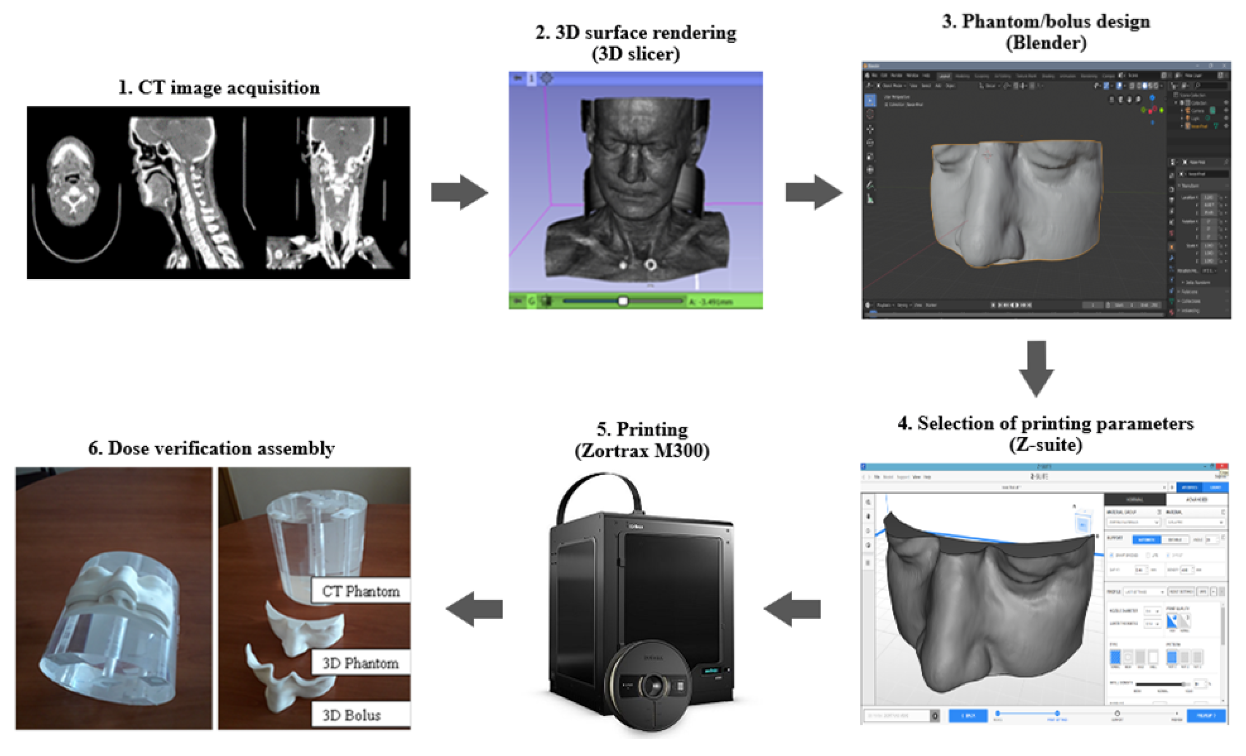
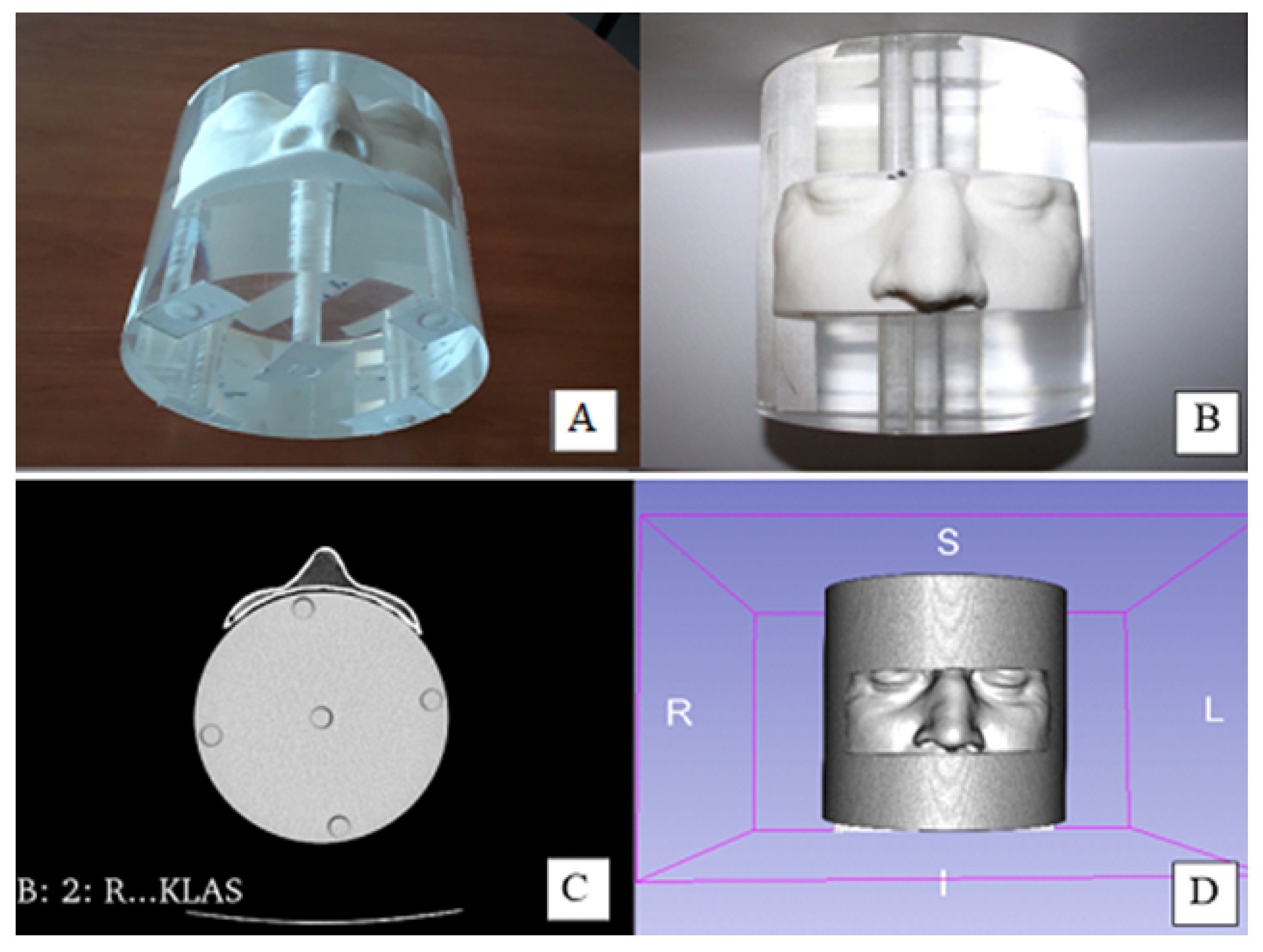
2.1. Development of Personalized 3D Devices

Fabrication of personalized 3D devices for clinical applications in radiotherapy was based on the reconstruction of a real cancer patient’s model according to CT images. The conversion of the data to a printer-friendly model was achieved using a specially developed data conversion algorithm and final realization of the 3D objects by applying 3D-printing technology. For this purpose, an original set of CT scans (CT scanner Siemens Light Speed RT16, Erlangen, Germany). in DICOM format displaying an anonymous patient’s anatomic area of interest (facial part with nose, cheeks and eyes covering tumor location) was selected. Surface rendering was performed using the open platform software 3D Slicer (slicer.org; US) to reconstruct a 3D model of the patient converting DICOM files to STL (stereolithography) format. The open software Blender (blender.org; Netherlands) was used to create a 3D-printed model of the desired object (3D phantom or 3D bolus) from the extracted STL files. The Zortrax M300 3D printer, which has a large printing volume (300 × 300 × 300 mm 3 ) was used to print the patient-specific devices (3D phantom and 3D bolus), by using fused deposition modeling (FDM) printing technology. The extracted STL file was converted into a special code able to run the commands that regulate the printing parameters of the desired 3D objects. The whole workflow chart of the creation and printing of 3D objects is shown in Figure 1.
Two types of 3D-printed devices were created using the technological procedure described above: patient-specific 3D phantom of the facial region of interest (Figure 2) and patient-specific 3D bolus of the same anatomic region (Figure 3). The 3D phantom was designed to be attached to the surface of a standard CT polymethyl methacrylate (PMMA) head phantom. Moreover, boluses of two different thicknesses (0.5 and 1.0 cm) were printed in order to evaluate the effect of bolus thickness on surface dose distribution. PLA material was used for the creation of desired 3D objects keeping a 90% infill ratio during printing of 3D phantom and 100% during printing of the 3D bolus. Selection of materials and infill ratio was based on our previous investigations [23,24,25]. The specific parameters used during the printing of the 3D objects are summarized in Table 1.

2.2. Physical Characterization of 3D-Printed Objects

The tissue equivalency and the geometric accuracy of both the 3D phantom and 3D bolus were evaluated by comparing the CT scanned objects with the original CT scans of the cancer patient. It is known that tissue equivalency of different materials depends on how the density of material correlates with the density of the biological tissue; however, density of material is also one of the most important factors defining X-ray attenuation properties of a material. Using the X-ray visualization technique, the tissue equivalency of material can be derived comparing Hounsfield units, HU (gray scale values at a certain points/regions of the image) for different organs, obtained from CT scans of real patients and CT scans taken of 3D-printed phantom and boluses.
The geometric accuracy and reproducibility of the 3D phantom was determined in terms of the Dice similarity coefficient (DSC), also referred to as overlap measure, between the CT images of the patient and phantom [26,27]. Reliable evaluation of DSC has been achieved by properly aligning selected CT scans obtained for both patient and phantom and manually adjusting areas of interest on both images. A DSC value of 1 indicates a perfect overlap between two analyzed volumes. In such case, the 3D-printed phantom would accurately reproduce the contours of patient surface and/or organs. In this work, the similarity coefficient was calculated using the open access software DSCImageCalc (Bradford, UK) [28]. In addition to the Dice similarity coefficient, five additional metrics (Jaccard Coefficient, Proportional Agreement, Cohen’s Kappa, Goodman ’I&’ Kruskal’s Gamma, Rogot–Goldberg Agreement) used in image segmentation analysis (i.e., analysis of shapes and areas) were calculated.

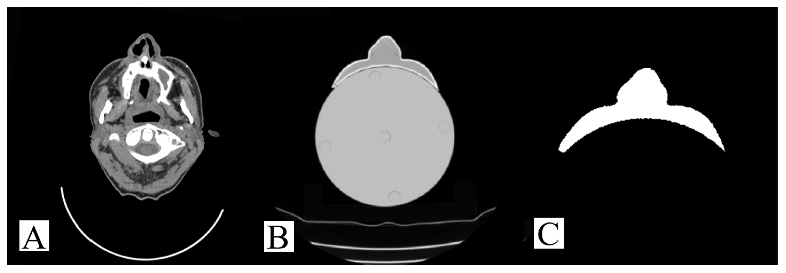
2.3. Conformity of 3D-Printed Boluses

In order to evaluate the conformity of the 3D-printed bolus to the patient surface and presence of air gap between the bolus and the skin, CT images were acquired for two 3D boluses of different thicknesses (0.5 and 1 cm thickness) attached to the 3D-printed phantom. The air gaps were analyzed in 2D slices by slicing through the CT scans and measuring the thickness of these air gaps.

2.4. Dosimetric Evaluation

Treatment plans were used to evaluate the influence of individualized 3D-printed boluses (0.5 and 1 cm thickness) on dose distribution. Three single field treatment plans were created for the 3D-printed patient-specific phantom using the Eclipse Treatment Planning System (developed by Varian Medical System, Palo Alto, CA, USA). One plan was created for the patient-specific phantom without a bolus, and two other plans were created for the cases when boluses of different thicknesses (0.5 cm and 1.0 cm) were placed on the surface of the patient-specific phantom. The target was delineated to cover the nose and cheeks while selecting a target volume of 3.8 cm3. The three plans were set with a single field 6 MV photon beam. The other parameters of the treatment plan were: field size of 5.6 cm × 3.6 cm and gantry angle 20°. The prescribed dose to the target was set to 2 Gy/fr. In order to assess the clinical feasibility of 3D boluses in the case of more complex radiotherapy modalities, three additional plans were created using five-fields IMRT, and setting the photon energy to 6 MeV FFF with gantry angles of 0°, 21°, 45°, 120° and 300°. Other treatment parameters, including prescribed dose and treatment target, were kept identical to the case of single field plan. The treatment plans with and without 3D-printed boluses were normalized for the maximum prescribed dose to cover 95%, 98% and 100% of the target volume, respectively. All plans were analyzed and compared in terms of the dose volume histogram (DVH) of the target volume. The following dosimetric parameters were estimated and compared for all the treatments: D95%, D98% and D100% (dose that covers at least 95%, 98% and 100% of the target volume, respectively).

3. Results and Discussion

Radiotherapy aims at irradiating a delineated tumor while minimizing the radiation dose delivered to the surrounding healthy tissues as much as possible. High energy (MeV) photons exhibit a skin-sparing effect as a result of the build-up region. This is useful when treating deep-seated tumors in a body, avoiding undesired early and late reactions of the skin. Nevertheless, if the tumor is superficial, the skin-sparing effect leads to tumor underexposure and higher risk of recurrence [7]. In order to overcome the skin-sparing effect in radiotherapy treatment, the application of 3D-printed bolus/compensating structure was explored in this study. It should be noted that since analysis was performed on a real patient with head and neck cancer, a 3D-printed patient-specific phantom was also needed for in-vitro dosimetric applications. Characterization and evaluation of feasibility of 3D-printed devices for their potential use in clinical applications has been performed focusing on three main aspects: tissue equivalency, geometric accuracy and conformity of the objects with the shape of the patient’s surface, and in vitro dose verification.

3.1. Physical Characterization of 3D Printed Objects

The most important factors to consider for 3D printing are the used material and the printing parameters (e.g., infill pattern, infill percentage, etc.) since they influence the properties of the printed object such as density and X-ray attenuation properties. Both PLA (polylactic acid) and ABS (acrylonitrile butadiene styrene) are common printing materials and were previously reported as tissue-equivalent [29]; however, based on our previous experience on 3D printing, PLA was used in this paper since, as opposed to ABS, it experiences no warping and deformation during printing due to its lower melting temperature (130–180 °C) [23,24,30,31].
The influence of the material’s infill ratio on 3D-printed structures was assessed comparing HUs derived from computed tomography DICOM images of the patient and 3D-printed objects (Figure 4). It was found that HU value (−32) measured in the patient-specific 3D-printed PLA phantom (at 90% infill ratio) was in the HU range characteristic for soft tissues in the facial region of interest; however, both PLA boluses printed at 100% infill ratio indicated significantly higher HU value of 469. It should be noted that the selection of different infill densities for 3D phantom and boluses was based on our previous study [23] where the impact of infill ratio on homogeneity of dose distribution in 3D-printed object was investigated. In this study, the performed 2D Gafchromic film dosimetry showed that when using 90% infill density for 3D printing, “patterned” dose distribution was observed beneath relatively thin printed objects (3D bolus) resulting in additional uncertainties in the measured doses [23]. This may particularly compensate for the lack of soft tissue equivalency in the bolus, which was printed using 100% infill ratio in order to avoid inhomogeneous dose distribution beneath the bolus. In the case of a massive object (3D phantom), the influence of the “patterning” effect was significantly reduced; thus enabling printing with the lower infill ratio (90%) and achieving density of the printed object comparable with a density of soft tissue.
The geometrical accuracy and reproducibility of the printed object depend on the errors introduced during each step of the 3D-printing process from image segmentation and subsequent modifications of the segmented model to printing and post-processing. Our patient-specific 3D-printed phantom had good geometrical accuracy. This was obtained by determining the Dice similarity coefficient, which measures the overlap between the CT images of the patient and phantom (Figure 5) [26,27]. The calculated DSC value was 0.957 and other similarity coefficients indicated good agreement between the external shape of the 3D-printed phantom and patient (Table 2).

3.2. Conformity of 3D-Printed Bolus

It is well known that the presence of air gaps between the bolus and patient’s surface indicate a lack of conformity. In addition, it is not possible to anticipate the size of the air gap in the treatment planning system, which results in inhomogeneity of the dose distribution. Botson et al. reported that, while using a 6 MV photon beam, a 4 mm air gap between patient’s surface and bolus leads to approximately 0–4% surface dose reduction while up to 10% reduction resulted from a 10 mm air gap, depending on different parameters such as field size and angle of incidence [11]. In order to evaluate the conformity of the 3D-printed boluses to the patient surface, each bolus was attached to the 3D phantom, which was mounted on the surface of the PMMA head phantom and the constructed phantom–phantom–bolus assemblies were CT-scanned. The 3D-printed PLA bolus provided a good fit to the patient phantom; however, some small air gaps were detected in CT images between the bolus and the patient-specific phantom surface (Figure 6). The size of the air gaps was evaluated by slicing through the CT scans. The largest air gaps were detected in the cheeks area. They varied from 0.4 to 2.1 mm for 0.5 cm thick bolus; while for the 1.0 cm bolus, it varied from 0.6 to 2.2 mm. The gaps measured in the nose region varied between 0.7 and 1.3 mm for the 0.5 cm thick bolus and was equal 1.4 mm for the 1.0 cm bolus. Observed air gaps were smaller as compared to those indicated by Botson et al. [11]. This indicates the potential of 3D-printed boluses in achieving higher conformity (small air gaps) to the irregular surfaces as compared with commercially available flat boluses and thus may improve dose distribution to the target. This good skin–bolus contact is of high importance especially in the case of highly conformal radiotherapy (e.g., IMT, VMAT), which delivers higher radiation doses and requires accurate tumor targeting.

3.3. In Vitro Dose Verification Using 3D-Printed Devices

In order to evaluate the influence of 3D boluses on the phantom surface dose distribution, three single-field plans were created: one without a bolus and two others with boluses of different thicknesses (0.5 cm and 1.0 cm) (Figure 7). The results indicated a lack of surface dose coverage without 3D bolus since the isodoses were shifted from the surface inside the phantom by 0.7 cm (for 95% coverage) and by 1.0 cm (for 99% coverage). More detailed information regarding the bolus effectiveness were obtained using dose volume histograms (DVH) for 95%, 98% and 99% surface volume coverage. The DVH results for the virtual target and dosimetric parameters derived from each of the investigated treatment plans are presented in Figure 8 and Table 3, respectively.
It was found that when no bolus is used, only 57.64% of the prescribed dose (i.e., 1.15 Gy from 2 Gy/fr) could be delivered to 95% of the target volume, while absorbed doses covering at least 97% and 99% of the investigated volume were 51.24% (1.02 Gy) and 47.96% (0.96 Gy) respectively. This indicates that the prescribed dose cannot be delivered efficiently to the target volume when no bolus is applied and will lead to the tumor underexposure. Dose coverage of the planned treatment volume (PTV) was significantly improved when 3D-printed bolus was attached to the surface of patient-specific phantom (Table 3). In the case of the 0.5 cm thick bolus, 95%, 97% and 99% of the same investigated surface volume were covered with 99.5% (1.99 Gy), 98% (1.96 Gy) and 97% (1.94 Gy) of the prescribed dose, respectively. Application of the 1.0 cm thick 3D bolus yielded results comparable with those observed by application of 0.5 cm thick bolus: the surface volume of (95%, 97% and 99%) was covered with 100% (2.0 Gy), 99.5% (1.99 Gy) and 98.5% (1.97 Gy), respectively).The results show that the surface dose coverage was almost equivalent with both 3D-printed boluses and increased by up to 60% when compared with no bolus indicating that the 3D boluses are good buildup materials.
The impact of 3D-printed boluses on surface dose coverage was also investigated in the case of a realistic clinical scenario involving IMRT with five irradiation fields (Figure 9 and Figure 10).
The results showed that 1.48 Gy of the prescribed 2 Gy dose was delivered to 99% of the target volume in the case of no bolus (Figure 10). Application of 1 cm boluses on the phantom shifted the dose toward the surface and allowed the delivery of 100% of the prescribe dose to the delineated target. Similar results were obtained for the 0.5 cm bolus (99% of the surface volume was covered with 98% of the prescribed dose) and thus, the 0.5 cm bolus is deemed satisfactory for the treatment of HNC with five intensity modulated beams of 6 MeV FFF. Analysis of single field and IMRT plans with and without 3D boluses indicated that application of patient-specific boluses can significantly improve the treatment outcome as a result of optimization of target dose coverage (Table 4).

4. Conclusions

We developed an algorithm for the conversion of patient’s CT data to a 3D-printer friendly interface for the printing of highly conformal 3D structures (boluses, phantoms) used for dose verification in radiotherapy with a geometric accuracy (DCS) of 0.957. Application of 3D-printed boluses allowed us to reduce air gaps between the bolus and irregular skin surfaces of a patient (phantom) to a minimum: to 0.4–2.1 mm for 0.5 cm bolus and 0.6–2.2 mm for 1.0 cm bolus. It was found that boluses of both thicknesses (0.5 and 1.0 cm) have comparable effectiveness as dose escalating devices, significantly increasing dose coverage of the target volume for both single field and intensity modulated fields treatment plans. Performed investigation has shown promising results regarding potential application of cost effective, personalized, 3D-printed boluses in combination with 3D-printed patient-specific phantoms for the verification of radiation dose plans, especially when treating concaved and uneven surfaces such as superficial head and neck cancer, which cannot be fitted adequately with a commercial bolus. It should be noted that discussed boluses and phantoms made of polylactic acid or other suitable thermoplastic are recyclable and may be reused for the printing of new 3D devices following the workflow implemented in this article.

Author Contributions

Conceptualization, D.A. and A.J.; Methodology, A.J., L.K. and J.L.; Software, B.G.U.; Validation, A.J.; Formal Analysis, M.I.; Investigation, L.K. and J.L.; Writing—Original Draft Preparation, A.J.; Writing—Review and Editing, D.A.; Supervision, D.A. All authors have read and agreed to the published version of the manuscript.

Funding

This work was partly supported by the research grant Reg. Nr. P-LL-21-74 of Lithuanian Research Council.

Institutional Review Board Statement

Not applicable.

Informed Consent Statement

Not applicable.

Conflicts of Interest

The authors declare no conflict of interest.

References

  1. Beadle, B.M.; Liao, K.P.; Elting, L.S.; Buchholz, T.A.; Ang, K.K.; Garden, A.S.; Guadagnolo, B.A. Improved survival using intensity-modulated radiation therapy in head and neck cancers: A SEER-Medicare analysis. Cancer 2014, 120, 702–710. [Google Scholar] [CrossRef] [Green Version]
  2. Mizowaki, T.; Norihisa, Y.; Takayama, K.; Ikeda, I.; Inokuchi, H.; Nakamura, K.; Kamba, T.; Inoue, T.; Kamoto, T.; Ogawa, O.; et al. Ten year outcomes of intensity-modulated radiation therapy combined with neoadjuvant hormonal therapy for intermediate- and high-risk patients with T1c–T2N0M0 prostate cancer. Int. J. Clin. Oncol. 2016, 21, 783–790. [Google Scholar] [CrossRef]
  3. Kamomae, T.; Itoh, Y.; Okudaira, K.; Nakaya, T.; Tomida, M.; Miyake, Y.; Oguchi, H.; Shiinoki, T.; Kawamura, M.; Yamamoto, N.; et al. Dosimetric impact of dental metallic crown on intensity-modulated radiotherapy and volumetric- modulated arc therapy for head and neck cancer. J. Appl. Clin. Med. Phys. 2016, 17, 234–245. [Google Scholar] [CrossRef] [PubMed]
  4. Kubo, K.; Monzen, H.; Ishii, K.; Tamura, M.; Kawamorita, R.; Sumida, I.; Mizuno, H.; Nishimura, Y. Dosimetric comparison of Rapid Plan and manually optimized plans in volumetric modulated arc therapy for prostate cancer. Phys. Med. 2017, 44, 199–204. [Google Scholar] [CrossRef]
  5. Didona, A.; Lancellotta, V.; Zucchetti, C.; Panizza, B.M.; Frattegiani, A.; Iacco, M.; Di Pilato, A.C.; Saldi, S.; Aristei, C. Is volumetric modulated arc therapy with constant dose rate a valid option in radiation therapy for head and neck cancer patients? Rep. Pract. Oncol. Radiother. 2018, 23, 175–182. [Google Scholar] [CrossRef]
  6. Puri, D.R.; Chou, W.; Lee, N. Intensity-modulated radiation therapy in head and neck cancers: Dosimetric advantages and update of clinical results. Am. J. Clin. Oncol. 2005, 28, 415–423. [Google Scholar] [CrossRef]
  7. Wojcicka, J.B.; Lasher, D.E.; McAfee, S.S.; Fortier, G.A. Dosimetric comparison of three different treatment techniques in extensive scalp lesion irradiation. Radiother. Oncol. 2009, 91, 255–260. [Google Scholar] [CrossRef]
  8. Kudchadker, R.J.; Antolak, J.A.; Morrison, W.H.; Wong, P.F.; Hogstrom, K.R. Utilization of custom electron bolus in head and neck radiotherapy. J. Appl. Clin. Med. Phys. 2003, 4, 321–333. [Google Scholar] [CrossRef]
  9. Moyer, R.F.; King, G.A.; Hauser, J.F. Lead as surface bolus for high-energy photon and electron therapy. Med. Phys. 1986, 13, 263–266. [Google Scholar] [CrossRef]
  10. Vyas, V.; Palmer, L.; Mudge, R.; Jiang, R.; Fleck, A.; Schaly, B.; Osei, E.; Charl, P. On bolus for megavoltage photon and electron radiation therapy. Med. Dosim. 2013, 38, 268–273. [Google Scholar] [CrossRef]
  11. Butson, M.J.; Cheung, T.; Yu, P.; Metcalfe, P. Effects on skin dose from unwanted air gaps under bolus in photon beam radiotherapy. Radiat. Meas. 2000, 32, 201–204. [Google Scholar] [CrossRef]
  12. Khan, Y.; Villarreal-Barajas, J.E.; Udowicz, M.; Sinha, R.; Muhammad, W.; Abbasi, A.N.; Hussain, A. Clinical and dosimetric implications of air gaps between bolus and skin surface during radiation therapy. J. Cancer Ther. 2013, 4, 1251–1255. [Google Scholar] [CrossRef] [Green Version]
  13. Sharma, S.C.; Johnson, M.W. Surface dose perturbation due to air gap between patient and bolus for electron beams. Med. Phys. 1993, 20, 377–378. [Google Scholar] [CrossRef] [PubMed]
  14. Malik, H.H.; Darwood, A.R.; Shaunak, S.; Kulatilake, P.; Abdulrahman, A.; Mulki, O.; Baskaradas, A. Three-dimensional printing in surgery: A review of current surgical applications. J. Surg. Res. 2015, 199, 512–522. [Google Scholar] [CrossRef]
  15. Yan, Q.; Dong, H.; Su, J.; Han, J.; Song, B.; Wei, Q.; Shi, Y. A Review of 3D Printing Technology for Medical Applications. Engineering 2018, 4, 729–742. [Google Scholar] [CrossRef]
  16. Mavili, M.E.; Canter, H.I.; Saglam-Aydinatay, B.; Kamaci, S.; Kocadereli, I. Use of three-dimensional medical modeling methods for precise planning of orthognathic surgery. J. Craniofac. Surg. 2007, 18, 740–747. [Google Scholar] [CrossRef] [Green Version]
  17. Fisher, M.; Applegate, C.; Ryalat, M.; Laycock, S.; Hulse, M.; Emmens, D.; Bell, D. Evaluation of 3-D printed immobilisation shells for head and neck IMRT. Open J. Radiol. 2014, 4, 322–328. [Google Scholar] [CrossRef] [Green Version]
  18. Su, S.; Moran, K.; Robar, J.L. Design and production of 3D printed bolus for electron radiation therapy. J. Appl. Clin. Med. Phys. 2014, 15, 194–211. [Google Scholar] [CrossRef] [Green Version]
  19. Kim, S.W.; Shin, H.J.; Kay, C.S.; Son, S.H. A customized bolus produced using a 3-dimensional printer for radiotherapy. PLoS ONE 2014, 9, 1–8. [Google Scholar]
  20. Unterhinninghofen, R.; Giesel, F.L.; Wade, M.; Kuypers, J.; Preuss, A.; Debus, J.; Sterzing, F. OC-0412: 3D printing of individual immobilization devices based on imaging ñ analysis of positioning accuracy. Radiother. Oncol. 2015, 115, S199–S200. [Google Scholar] [CrossRef] [Green Version]
  21. McCowan, P.; Sasaki, D.; Jensen, M.; Rickey, D.; Dubey, A.; Harris, C.; Aviles, J.A.; McCurdy, B. On The Physical and Dosimetric Properties of 3D Printed Electron Bolus Fabricated Using Polylactic Acid. Radiother. Ocol. 2016, 120, S47. [Google Scholar] [CrossRef] [Green Version]
  22. Mayer, R.; Liacouras, P.; Thomas, A.; Kang, M.; Lin, L.; Simone, C.B. 3D printer generated thorax phantom with mobile tumor for radiation dosimetry. Rev. Sci. Instrum. 2015, 86, 074301. [Google Scholar] [CrossRef]
  23. Lali, K.; Artūras, A.; Reda, Č.; Dimitrova, T.; Jurgita, L. 3D printed boluses usage in radiotherapy. In Proceedings of the 14th International Conference on Medical Physics, Kaunas, Lithuania, 7–9 November 2019; pp. 125–128. [Google Scholar]
  24. Sevcik, A.; Adliene, D.; Laurikaitiene, J.; Nedzinskiene, R.; Masiulyte, I. Low energy deposition patterns in irradiated phantom with metal artefacts inside: A comparison between FLUKA Monte Carlo simulation and GafChromic EBT2 film measurements. Nucl. Instrum. Methods Phys. Res. B 2020, 478, 142–149. [Google Scholar] [CrossRef]
  25. Adlienė, D.; Jaselskė, E.; Urbonavičius, B.G.; Laurikaitienė, J.; Rudžianskas, V.; Didvalis, T. Development of 3D printed phantom for dose verification in radiotherapy for the patient with metal artefacts inside. In Proceedings of the World Congress on Medical Physics and Biomedical Engineering, Prague, Czech Republic, 3–8 June 2018; Springer: Berlin/Heidelberg, Germany, 2019; Volume 68, pp. 643–647. [Google Scholar]
  26. Taha, A.A.; Hanbury, A. Metrics for evaluating 3D medical image segmentation: Analysis, selection, and tool. BMC Med. Imaging 2015, 15, 29. [Google Scholar] [CrossRef] [Green Version]
  27. Zou, K.H.; Warfield, S.K.; Bharatha, A.; Tempany, C.M.; Kaus, M.R.; Haker, S.J.; Wells, I.I.I.W.M.; Jolesz, F.A.; Kikinis, R. Statistical validation of image segmentation quality based on a spatial overlap index. Acad. Radiol. 2004, 11, 178–189. [Google Scholar] [CrossRef] [Green Version]
  28. Lawton, T. DSC ImageCalc—Software for Determining Similarity Coefficients for the Analysis of Image Segmentations. J. Open Res. Softw. 2017, 5, 28. [Google Scholar] [CrossRef] [Green Version]
  29. Tino, R.; Yeo, A.; Leary, M.; Brandt, M.; Kron, T. A Systematic Review on 3D-Printed Imaging and Dosimetry Phantoms in Radiation Therapy. Technol. Cancer Res. Treat. 2019, 18, 1533033819870208. [Google Scholar] [CrossRef]
  30. Ehler, E.D.; Barney, B.M.; Higgins, P.D.; Dusenbery, K.E. Patient specific 3D printed phantom for IMRT quality assurance. Phys. Med. Biol. 2014, 59, 5763–5773. [Google Scholar] [CrossRef] [PubMed]
  31. Burleson, S.; Baker, J.; Hsia, A.T.; Xu, Z. Use of 3D printers to create a patient-specific 3D bolus for external beam therapy. J. Appl. Clin. Med. Phys. 2015, 16, 166–178. [Google Scholar] [CrossRef]
Figure 1. The workflow chart for creating and printing of patient-specific 3D devices for clinical use in radiotherapy.
Applsci 11 08657 g001
Figure 2. 3D-printed patient-specific phantom: (A,B) Phantom–phantom assembly, consisting of the printed phantom attached to the surface of CT head phantom; (C) CT image of the phantom–phantom assembly; (D) model of phantom–phantom assembly reconstructed from CT scans.
Applsci 11 08657 g002
Figure 3. 3D-printed bolus: (A) frontal view; (B) lateral view; (C) boluses with different thicknesses (0.5 cm and 1.0 cm).
Applsci 11 08657 g003
Figure 4. CT scans of the objects of interest: (A) CT scan of real HNC patient, with indicated HU values for different organs; (B) image of phantom–phantom–bolus assembly; (C) CT scan of the PMMA head phantom with attached 3D-printed phantom and 3D-printed bolus on it, with indicated HU values.
Applsci 11 08657 g004
Figure 5. CT image of the patient (A); CT image of the 3D-printed phantom located on the surface of CT head phantom (B); overlapping of patient’s and of 3D-printed phantom’s CT images obtained using open access software DSCImageCalc (C).
Applsci 11 08657 g005
Figure 6. Marked air gaps between patient-specific phantom and each of the 3D-printed boluses: (A) 0.5 cm thick bolus; (B) 1.0 cm thick bolus.
Applsci 11 08657 g006
Figure 7. Isodose distribution in single field treatment plans: (A) CT head phantom with attached patient-specific phantom; (B) patient-specific phantom with attached 0.5 cm thick bolus; (C) patient-specific phantom with attached 1.0 cm thick bolus.
Applsci 11 08657 g007
Figure 8. Dose volume histograms for the three single-field plans obtained for the patient-specific phantom: without bolus (blue), with 0.5 cm thick 3D-printed bolus attached to the phantom surface (gray) and 1.0 cm thick 3D-printed bolus attached to the phantom surface (red).
Applsci 11 08657 g008
Figure 9. Isodose distributions in five-field intensity-modulated radiation therapy plans: (A,B) sagittal and frontal views of CT head phantom with attached patient-specific phantom; (C) patient-specific phantom with attached 0.5 cm thick bolus; (D) patient-specific phantom with attached 1.0 cm thick bolus.
Applsci 11 08657 g009
Figure 10. Dose volume histograms for three IMRT plans obtained for the patient-specific phantom: without bolus (blue), with 0.5 cm 3D bolus (red) and 1.0 cm 3D bolus (gray).
Applsci 11 08657 g010
Table 1. Printing parameters.
SettingsValues
Bed temperature30 °C
Extruder temperature207 °C
Layer height0.14 mm
Fill density (bolus)100%
Fill density (phantom)90%
Fill patternRectilinear
Nozzle diameter0.4 mm
PLA Filament diameter1.75 mm
Table 2. Similarity coefficients calculated using the DSCImageCalc software.
CriteriaValue
Sorensen–Dice Coefficient (DICE)0.957
Jaccard Coefficient (JAC)0.917
Proportional Agreement (PA)0.998
Cohen‘s Kappa (KAP)0.956
Goodman & Kruskal‘s Gamma (GKG)0.913
Rogot–Goldberg Agreement (RGA)0.978
Table 3. Calculated difference between doses calculated by TPS and prescribed dose for single-field plan.
A Single-Field PlanDifference from Prescribed Dose 2 Gy
D95%D97%D99%
Gy%Gy%Gy%
Without bolus0.8540.00.9850.01.0452.0
With 0.5 cm bolus0.010.50.042.00.063.0
With 1.0 cm bolus0.000.00.010.50.031.5
Table 4. Calculated difference between doses calculated by TPS and prescribed dose for the IMRT plan.
IMRT PlanDifference from Prescribed Dose 2 Gy
D95%D97%D99%
Gy%Gy%Gy%
Without bolus0.15.140.178.640.5226.04
With 0.5 cm bolus0.0070.350.0080.40.020.98
With 1.0 cm bolus000000
Publisher’s Note: MDPI stays neutral with regard to jurisdictional claims in published maps and institutional affiliations.

