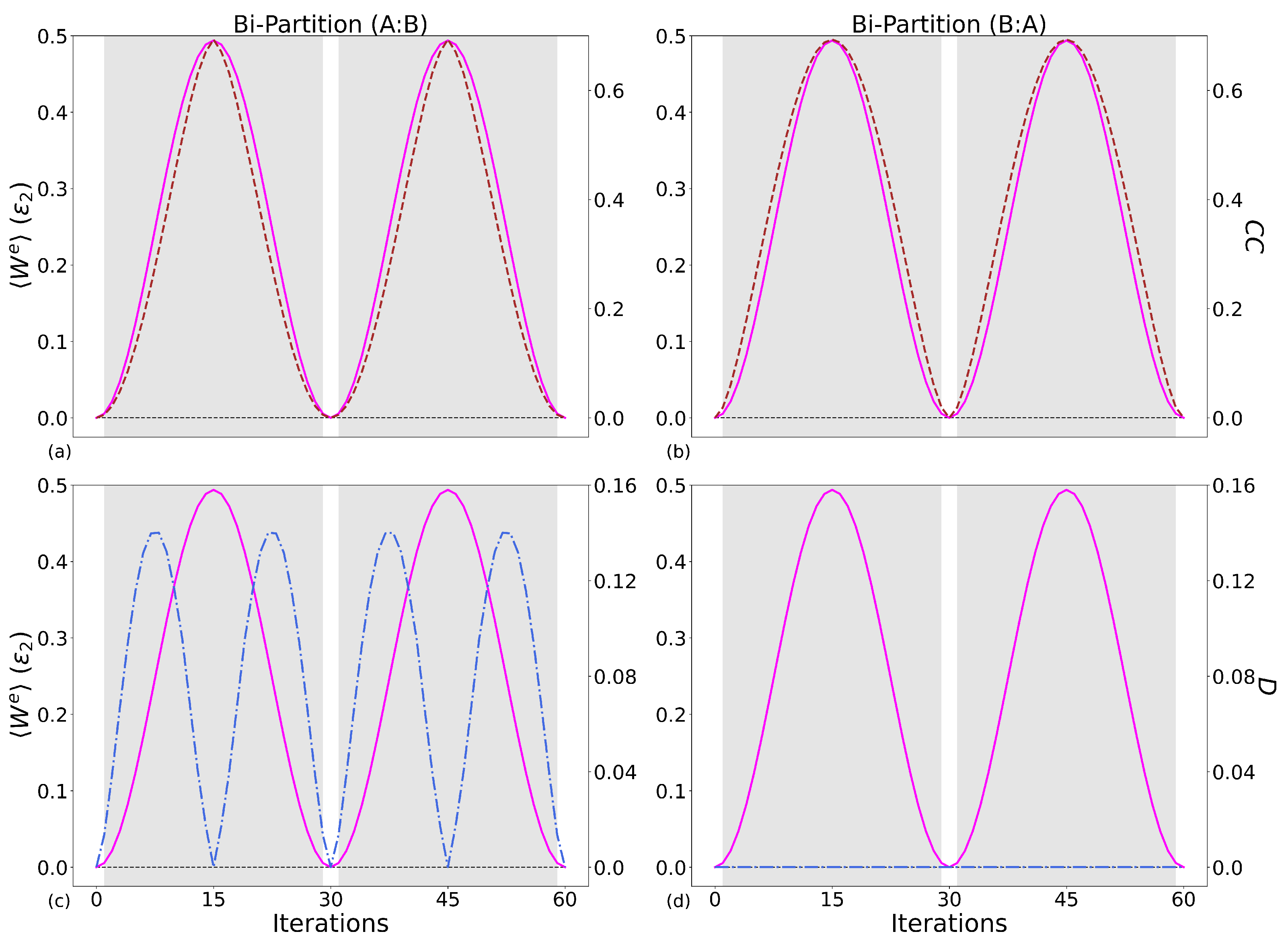
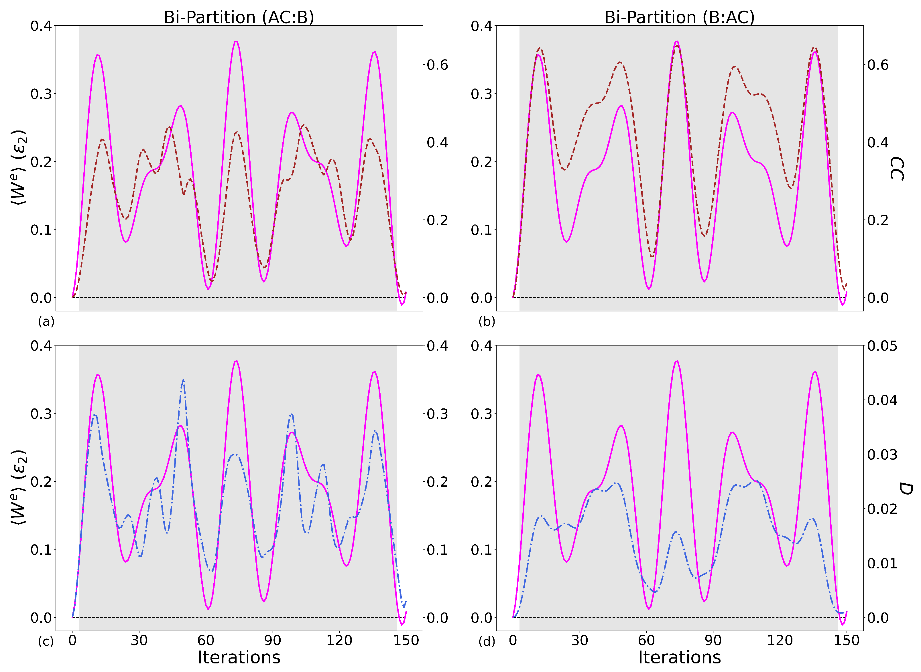
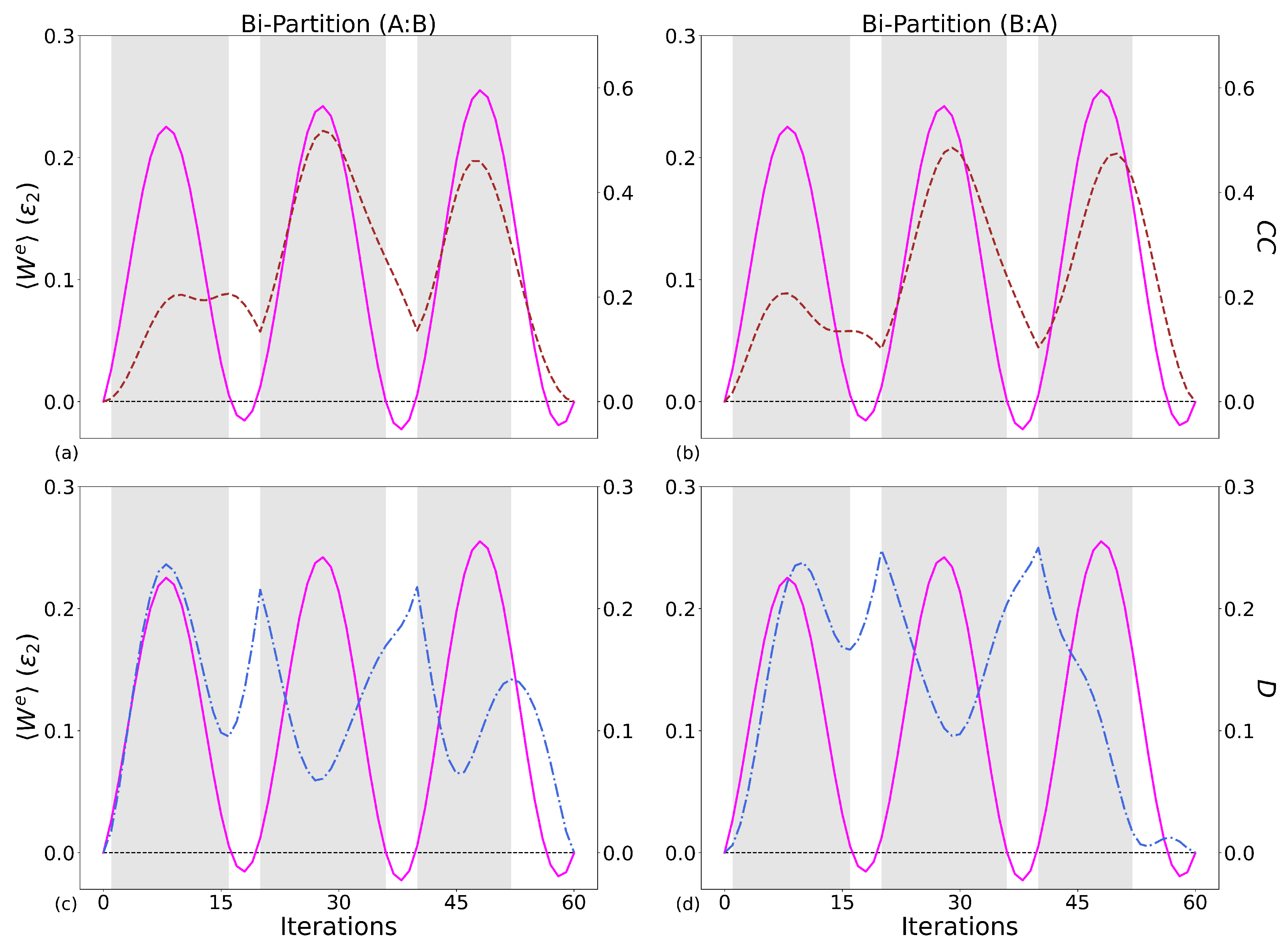
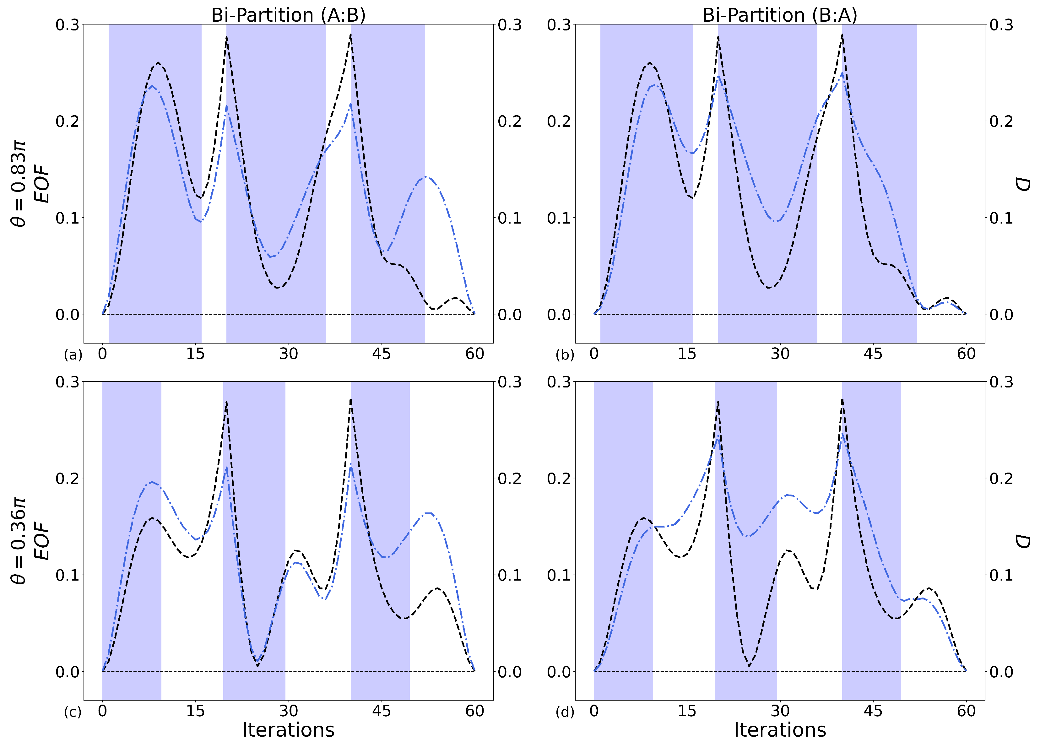
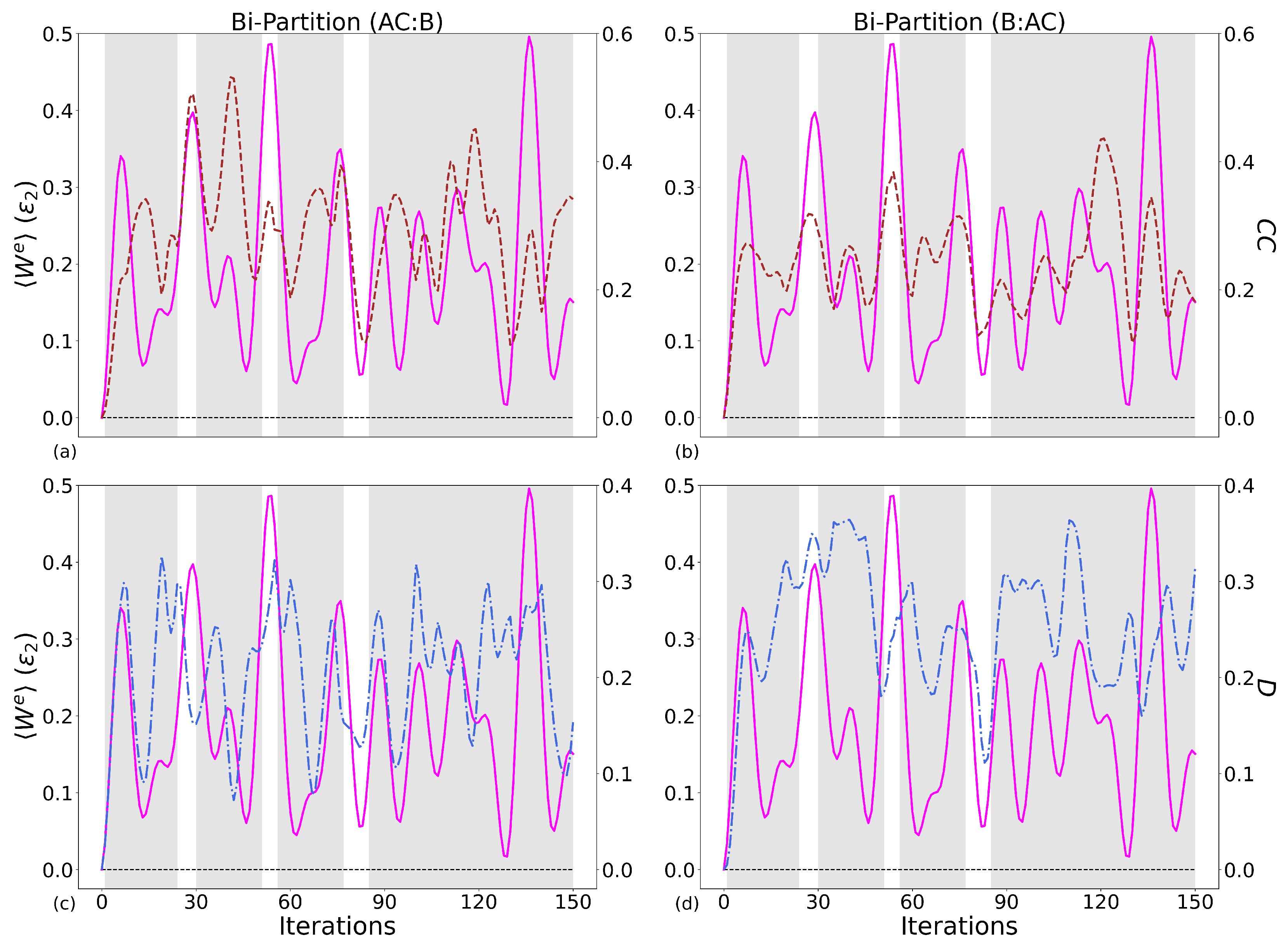
We consider a system composed either of two (A and B) or of three (A, B, and C) qubits that interact with each other through the use of NRCGs (
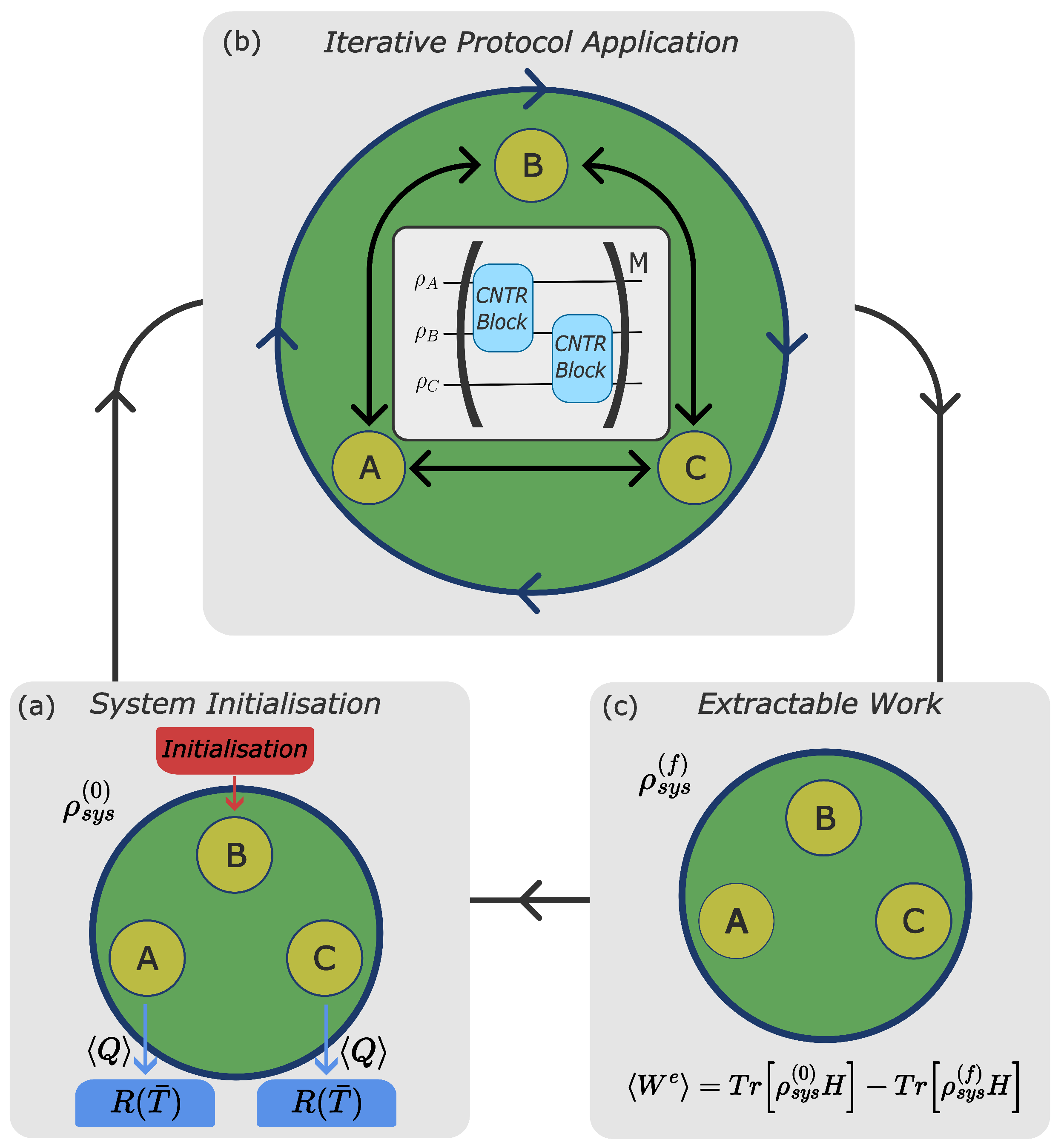
Figure 2). Our system will undergo one operational cycle that consists of distinct steps: initialisation, where qubits are connected to reservoirs and heat is exchanged, and iterative protocol application, where qubits, now disconnected from the reservoirs, are driven by gates and work is extracted.
2.1. Initialisation
First, we describe the initialisation step. The component qubits of the working medium are coupled to their respective reservoirs, which initialise or re-initialise them to some initial state. Qubits A and C are initialised in identical thermal states at equal temperatures
by coupling to the thermal reservoirs
. In the case where qubit-B is initialised in a thermal state,
initialisation in
Figure 1a is performed by the reservoir
. It is important to note that there is no initial correlation between any two qubits. The single-qubit thermal state is a Gibbs state defined as [
49]
where
is the partition function,
is the inverse temperature parameter,
is the Boltzmann constant, and
are the eigenvalues of the single-qubit Hamiltonian. This is given by
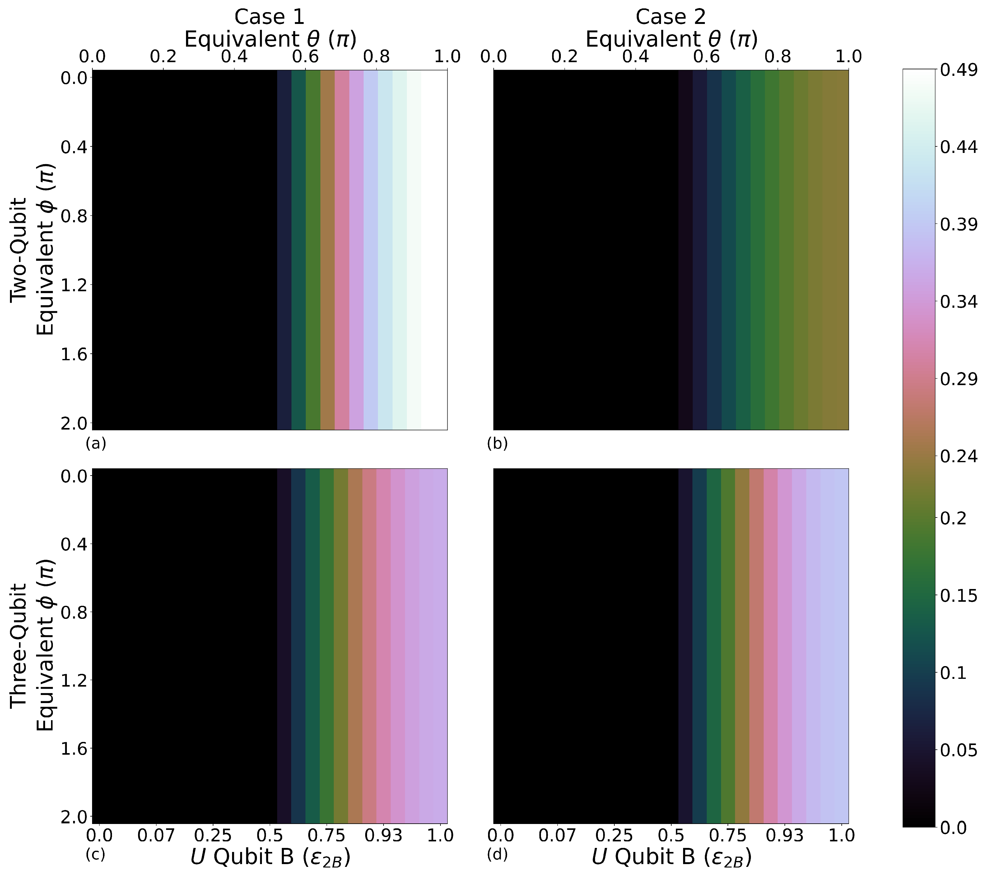
As reference systems, we consider the ones with each qubit prepared in a thermal state: here, there are no initial quantum coherences. We compare these with the systems in which qubit-B is prepared in a pure state; then, initial quantum coherence will transfer through the qubits when a circuit is applied. This allows for probing how initial quantum coherences affect the system’s capabilities as a heat engine. Qubit-B is initialised in a pure state as
, where
with a value of
which ranges from
, while
ranges from 0 to
. For this investigation, we will consider the full range of
and
values. Here,
is the ground state and
is the excited state. In this paper, energies are given in units of
, which is then set to 1 in all calculations.
The total initial Hamiltonian is non-interacting and of the form,
with
given by Equation (
2) and
and
for two and three qubits, respectively. Equation (
3) represents the Hamiltonian for the total system at any time, including at the point of measurement, except when NRCGs are applied, inducing interactions between qubits.
To understand the flow of heat through the system, we first define two quantities: the average internal energy and the extractable work. The average internal energy is quantified with the value and has the form , where is the density matrix of either the component qubits or the total system, and is the corresponding Hamiltonian, for the component qubits or for the total system.
We now characterise the flow of heat through the system by first discussing the heat exchanged between the qubits and the environment when resetting the system. Qubits A and C are initialised at a different initial energy to qubit-B, allowing for the identification of which components of the working medium are ‘hot’ and ‘cold’, which is important when describing the system as a thermal engine. Explicitly:
identifies qubit-B as the ‘hot’ component, that is, the qubit with the highest initial energy;
identifies qubit-B as the ‘cold’ component, that is, the qubit with the lowest initial energy.
Here is the energy of qubit j after initialisation, that is, at the beginning of the driving cycle, and and for two and three qubits. The heat exchanged during (re)initialisation of qubit j is then , with the internal energy of qubit j at the end of the driving part of the operational cycle, that is, just before (re)initialisation.
The definition of allows us to identify the direction of the flow of heat: is positive when energy is transferred from a reservoir to a component of the working medium during the (re)initialisation phase of the operational cycle.
Further, the system has no intrinsic interaction between the qubits outside of those facilitated by NRCGs, allowing for convenient resetting of the system back to initial conditions.
2.2. Protocol Design and Application
The second step of the NRCG-driven quantum heat engine is the iterative protocol application shown in
Figure 1b. This is the step in which the working fluid (the qubits), as a closed system, is driven by the unitaries represented by the applied gates, and work is produced. We use the convention [
5] that a reduction in the total energy of the system during this step corresponds to the positive extractable work
, with
the state of the working fluid after initialisation and
the state of the working fluid at the end of the driving protocol. This definition of extractable work will be used throughout the paper. We now describe the NRCGs, then the protocols.
Qubits’ correlation, which a CNOT gate may induce, may lead to a quantum advantage in the operation of a quantum heat engine [
20]. The NRCG is a method of partially applying a CNOT gate; it is a unitary operation given by [
50],
Here, the matrix representation of the gates is written in the standard basis
,
and
,
. The first subscript represents the control qubit, and the second subscript, the target qubit. This type of gate may generate entanglement between two qubits, which adds a level of quantumness to the system, with the standard form of the CNOT gate recovered when
.
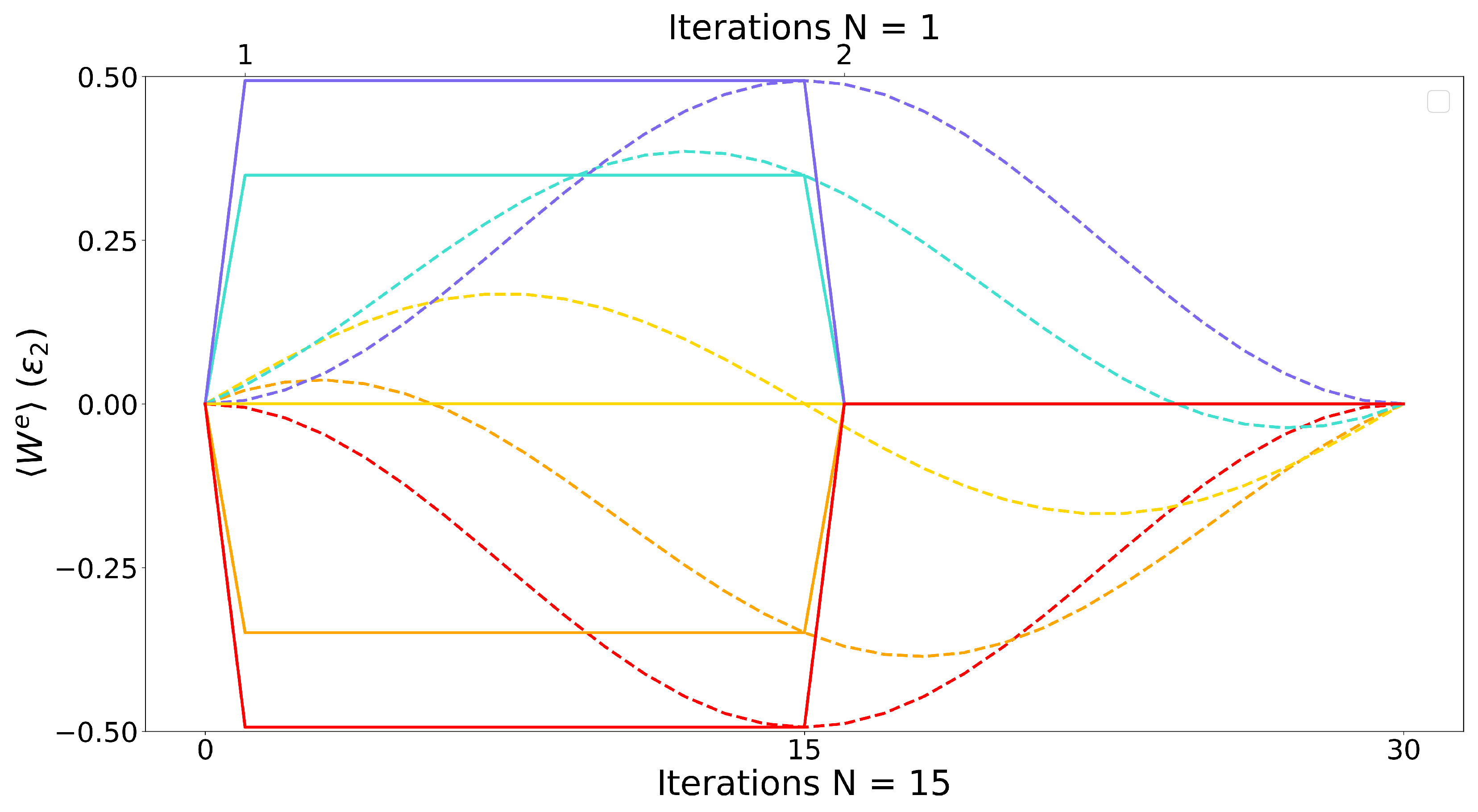
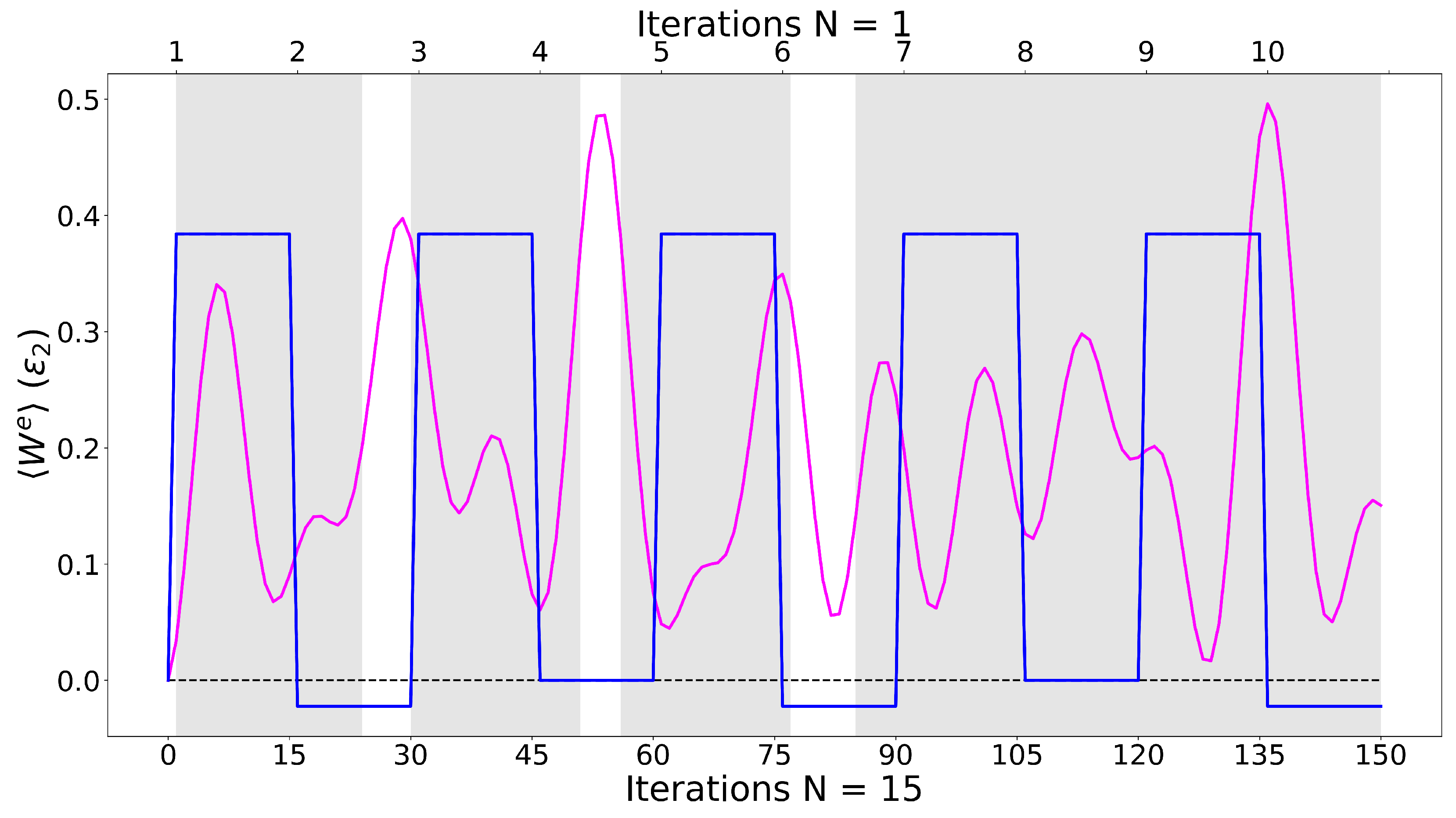
N consecutive applications of an NRCG with the same control and target qubits could be seen as a trotterisation of the CNOT gate, aiming at explicitly implementing the gate, in the limit of a large
N, as an adiabatic dynamic. In this sense, our protocols give explicit access to intermediate states, e.g., allowing for the opportunity to use states with different degrees of entanglement from the end result of the full CNOT gate. Here,
is chosen, as it shows good access to intermediate states [
51] (we note that, for
, there is no further appreciable improvement to the system’s performance when considering
).
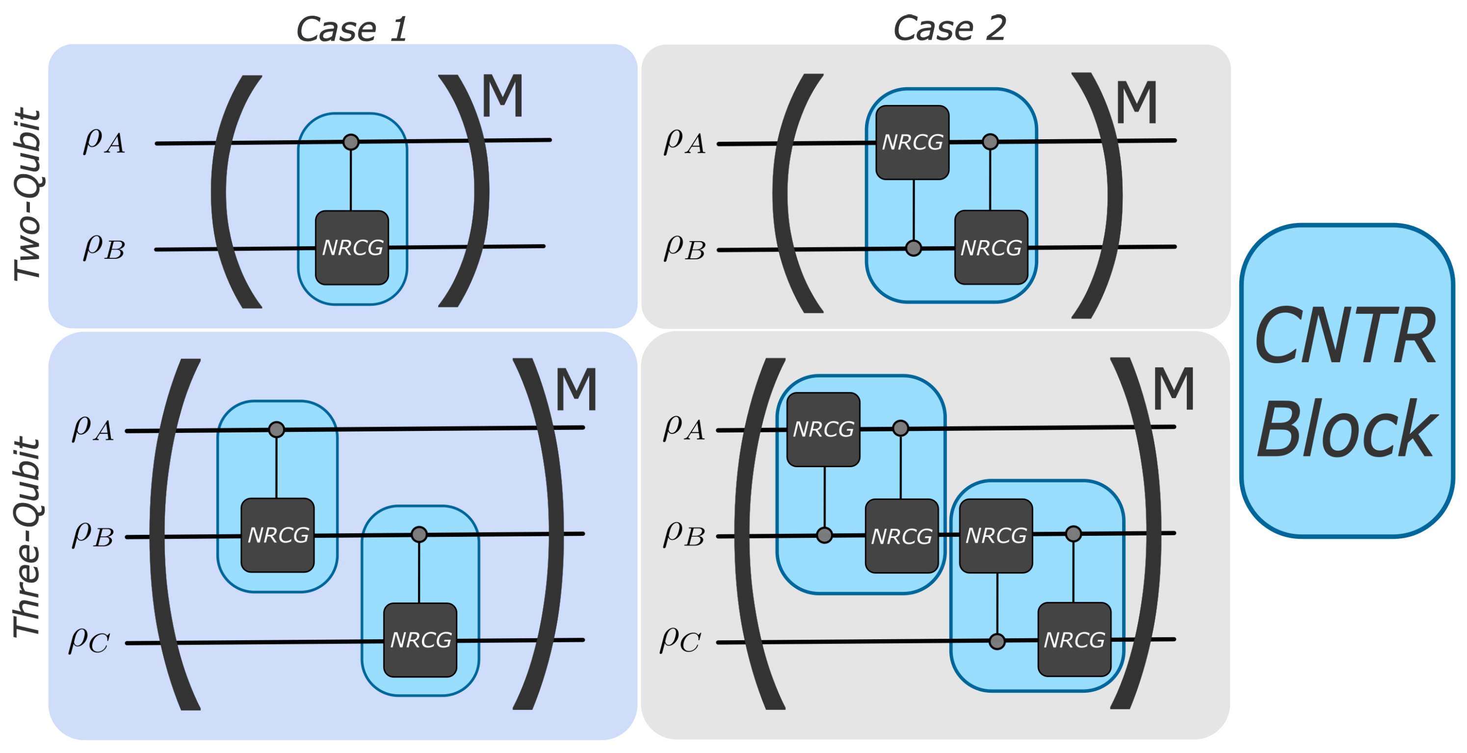
A schematic of the building blocks of the protocols is shown in
Figure 2: we consider systems of two and three qubits for each protocol and examine two ways of applying interactions. The two-qubit system is recovered with the removal of qubit-C and the second ‘controlled block’ (CNTR block) in
Figure 1b. Explicitly:
Case 1, one gate for each ‘CNTR block’, see left column of
Figure 2: Working systems are composed of qubits A and B and A, B, and C. For the two-qubit system, qubit-A is the control qubit, while qubit-B is the target qubit. For the three-qubit system: qubit-A is the control qubit with qubit-B being the target qubit, then qubit-B is the control qubit with qubit-C being the target qubit.
Case 2, two gates for each ‘CNTR block’, see the right column of
Figure 2: Working systems are composed of qubits A and B and A, B, and C. All qubits are either a control or a target qubit over the course of one iteration.
The system is evolved, according to the quantum circuits in
Figure 2, with the evolution
, where
is the initial density matrix of the total system and
indicates the total density matrix at the end of the protocol. The unitary
represents the controlled gates specified in
Figure 2, as appropriate to each protocol, with NRCGs of the form in Equation (
4). For example,
for Case 1 two-qubit system, with
M the number of iterations according to the corresponding panel of
Figure 2. The simulation of the protocol is implemented by directly applying
in
.
We note that only for Case 1 and the two-qubit system, multiples of N iterations of the circuit will be equivalent to the application of multiple standard CNOT gates; however, fractions of N iterations will allow access to intermediate states in the evolution leading to a CNOT.
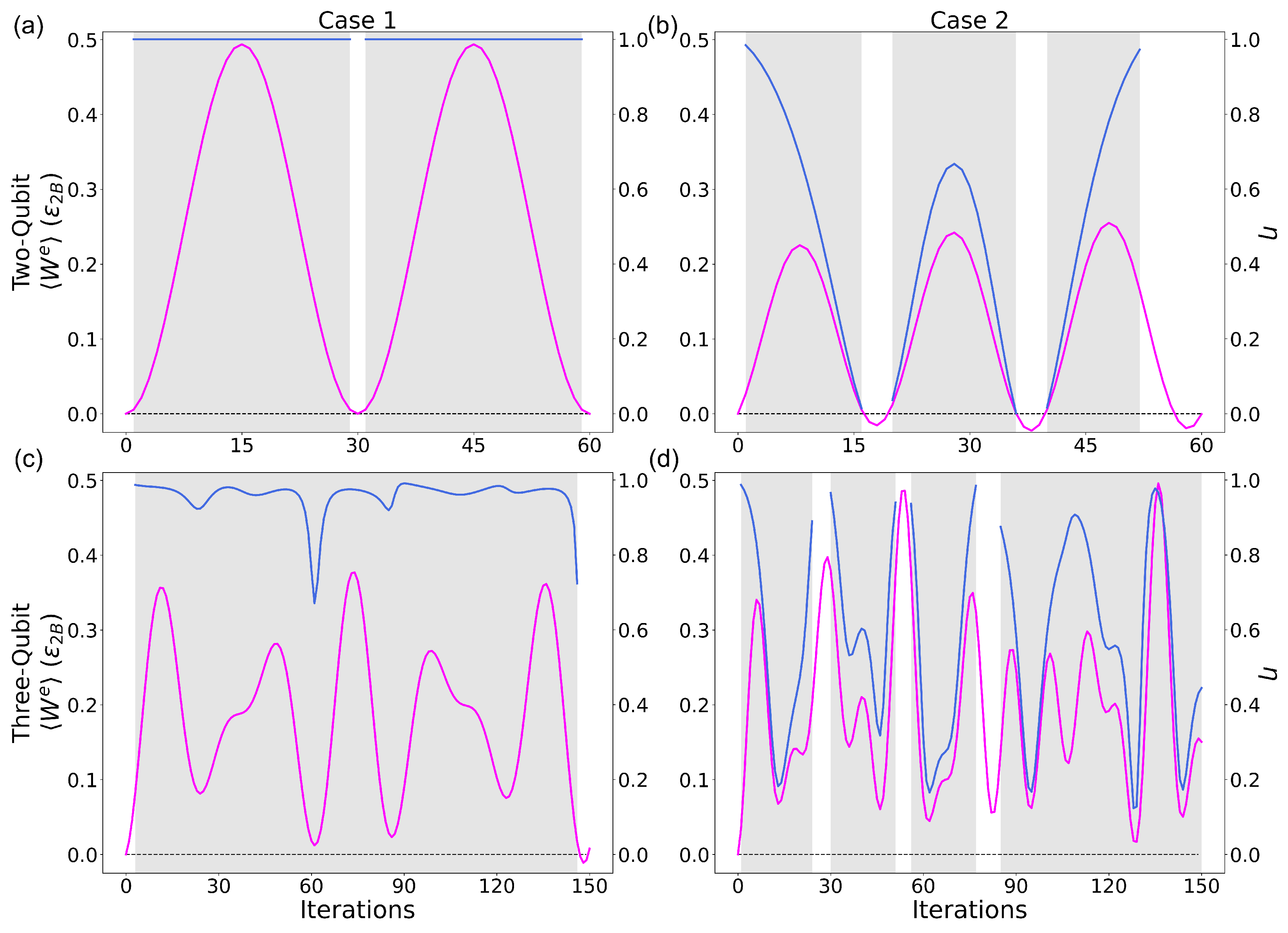
These protocols are iteratively applied to the system and can be halted at a chosen number of iterations, which can be optimised for either a maximum or a specific value of . Afterwards, the system will then proceed back to the initialisation step.
When qubit-B is initially the most energetic, we can define qubits A and C as the cold components, and qubit-B as the hot component of the working medium. Identifying a heat engine regime can then be achieved with the fulfilment the following conditions
with
and
. Here
is the initial and
the final state of qubit
j, the latter being the trace over the degrees of freedom of qubits’ other than
j of the final state of the system. Conditions (
5) are specific to qubit-B being the hot component. While the system does not always operate as a heat engine over all protocols and initial conditions, it does so for the regions corresponding to the highest production of extractable work.