Abstract
Crosstalk is the primary source of noise in quantum computing equipment. The parallel execution of multiple instructions in quantum computation causes crosstalk, which causes coupling between signal lines and mutual inductance and capacitance between signal lines, destroying the quantum state and causing the program to fail to execute correctly. Overcoming crosstalk is a critical prerequisite for quantum error correction and large-scale fault-tolerant quantum computing. This paper provides an approach for suppressing crosstalk in quantum computers based on multiple instruction exchange rules and duration. Firstly, for the majority of the quantum gates that can be executed on quantum computing devices, a multiple instruction exchange rule is proposed. The multiple instruction exchange rule reorders quantum gates in quantum circuits and separates double quantum gates with high crosstalk on quantum circuits. Then, time stakes are inserted based on the duration of different quantum gates, and quantum gates with high crosstalk are carefully separated in the process of quantum circuit execution by quantum computing equipment to reduce the influence of crosstalk on circuit fidelity. Several benchmark experiments verify the proposed method’s effectiveness. In comparison to previous techniques, the proposed method improves fidelity by 15.97% on average.
1. Introduction
Quantum computing (QC) is a new computing mode that employs quantum information units to perform calculations based on quantum mechanical laws such as quantum entanglement and quantum superposition. Because of the superposition of quantum mechanics, quantum computing systems can solve some problems faster than traditional computers such as quantum image processing [1], cryptography [2], artificial intelligence [3], database search [4], and so on.
Quantum computing has advanced rapidly in recent years, with some public demonstrations of prototype quantum computing systems. Because hardware manufacturing technology is limited by many factors, including inaccurate quantum control and external interference [5], the noisy intermediate-scale quantum (NISQ) computing equipment will inevitably make mistakes in the execution of quantum circuits [6], limiting the execution ability of quantum computers [7,8]. As a result, developing new quantum algorithms and conducting quantum computing research on NISQ quantum computing equipment are critical for making the best use of scarce hardware resources and minimizing the noise impact of quantum algorithms on the equipment.
Crosstalk is a significant source of noise in NISQ quantum computing devices [9,10]. The driving signal focused on a specific qubit propagates to the adjacent qubit in NISQ hardware devices, resulting in crosstalk [11]. Previous research has shown that simultaneous execution of multiple gates causes significant crosstalk [9,10,11,12]. In various quantum computing devices, the error rate of quantum gates between every two qubits is 1–5% [13]. Crosstalk has been shown in studies to significantly increase the error rate and negatively impact the successful implementation of quantum circuits [9,10,12]. How to suppress crosstalk has emerged as a critical issue to address in order to improve the success rate of quantum circuits.
In the existing research, Murali et al. proposed crosstalk mitigation scheduling on noisy quantum computers, which uses the method of inserting barriers to mitigate crosstalk, but it will result in excessively long execution time of quantum circuits, which will inevitably lead to decoherence errors [9]. Lei Xie et al. proposed reordering instructions to reduce crosstalk in quantum computers, which greatly increased the parallelism of quantum circuit execution and reduced crosstalk [12].
However, there are a large number of executable quantum gates in NISQ quantum computing devices. Extending the instruction exchange rules will help reduce the noise impact caused by crosstalk even further. Meanwhile, different quantum gates in NISQ quantum computing devices have different durations [14]. Ignoring quantum gate duration may result in the simultaneous execution of multiple double quantum gates, which cannot effectively reduce crosstalk. In the implementation of NISQ quantum computing equipment, taking into account the difference in duration of different quantum gates can help reduce crosstalk caused by quantum circuits.
To address the aforementioned issues, this paper proposes multiple instruction ex-change rules for more executable quantum gates, which are then used to separate quantum gates with high crosstalk. Taking into account the duration of various quantum gates, a time stake insertion method is proposed in this process, by which the occupied state of qubits is updated to improve the parallelism of quantum circuits, and the influence of crosstalk on circuits is greatly reduced.
The rest of this paper is organized as follows: Section 2 introduces the fundamentals of quantum computing; Section 3 analyzes methods for reducing crosstalk in scheduling strategies; Section 4 and Section 5 describe the proposed multiple instruction exchange rules and the time stake insertion algorithm while taking into account different quantum gate durations; Section 6 discusses the experimental results; and Section 7 provides a summary of this paper.
2. Background of Quantum Circuit
2.1. Quantum Qubit and Quantum Gate
In a classical computer, information is stored in binary form, with two definite states, 0 and 1. In quantum computers, qubits, as the basic unit for storing information, also exist in two ground states: and . Unlike the bits in classical quantum computers, qubits can be in a superposition state, which can generally be expressed as , where , and are the probability amplitudes corresponding to the two ground states and [15].
Quantum gate is the basic operation performed on qubits in quantum computing. A single quantum gate acts on a single qubit, and a double quantum gate acts on two qubits. As shown in Figure 1. The CNOT gate flips the target qubit (represented by the graph) if and only if the control qubit (represented by the black dot graph ) is in the state. If the state of the control qubit is , the CNOT gate flips the state of the target qubit. If the state of the control qubit is , the state of the target qubit remains unchanged.
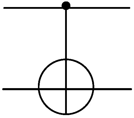
Figure 1.
The gate.
A quantum gate acting on qubits can be represented by a unitary matrix [16]. Quantum gates on NISQ quantum computing devices can be divided into single quantum gates and double quantum gates. In this paper, we consider the majority of the gates on NISQ quantum computing devices including single quantum gates such as X gate, Z gate, Y gate, H gate, T gate, T+ gate, S gate and S+ gate, as well as revolving gates such as gate, gate, gate, gate, and gate. Double quantum gates include gate. Their corresponding symbols and unitary matrices are shown in Table 1.

Table 1.
Quantum gate symbol and corresponding unitary matrix.
2.2. Quantum Circuit and Unitary Matrix Calculation
A quantum circuit is a model used to describe a quantum algorithm in quantum computing [17]. A quantum circuit is made up of qubits and a series of quantum gates that act on these qubits. Figure 2 depicts a quantum circuit.
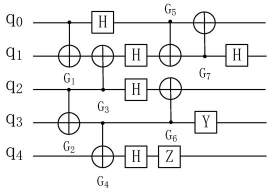
Figure 2.
Example of a quantum circuit diagram.
There are several functionally consistent quantum circuit representations in a quantum algorithm. The unitary matrix equivalence [18] can be used to determine whether two quantum circuits have equal functions. When two quantum circuits have the same functions, their unitary matrices are also the same. The symbolic representation of a unitary matrix in a quantum circuit is shown in Table 2, and the calculation rules are shown in Table 3.
Table 2.
Symbolic representation of unitary matrix.
Table 3.
Calculation rules of unitary matrix.
2.3. Noise in NISQ Computing Equipment
Due to manufacturing technology limitations and other factors such as external interference, quantum computing equipment will inevitably produce noise. Table 4 displays the parameter information for NISQ computing equipment. The average error rate of single-qubit operations is less than 0.1%, and the error rate of double quantum gates between two qubits is between 2% and 8%, with an average of 3.8%.
Table 4.
Parameter information of superconducting computing equipment.
3. Crosstalk Analysis in Scheduling
3.1. Hardware Causes of Crosstalk
In NISQ computing equipment, due to the defects of hardware manufacturing, the driving signal focused on a specific qubit will spread to the neighboring qubits, destroying their states and resulting in crosstalk. Existing methods for reducing crosstalk are classified as hardware strategies and scheduling strategies. Tunable couplers [19,20] and fixed-frequency qubit architectures [21,22] are two common hardware strategies. Although quantum computing devices are constantly slowing down crosstalk via hardware strategies [23,24], crosstalk still exists in actual quantum computing devices and has a significant impact on quantum circuit fidelity [23,25].
3.2. Reasons of Crosstalk in Scheduling
In this paper, we propose a crosstalk-mitigating scheduling strategy, which is a method for adjusting the quantum circuits that must be executed during the execution phase without changing their function. The difference between this strategy and the hardware strategy is that it focuses on quantum circuit optimization rather than quantum device hardware optimization.
To reduce the influence of crosstalk on the fidelity of quantum circuits through scheduling strategies, it is necessary to understand the causes of crosstalk during the execution of quantum circuits.
In order to explore the reason for crosstalk in scheduling strategies, this paper adopts the random benchmark test (RB) [26,27] to evaluate the quantum gate error rate. In the random benchmark test (RB), the error rate of a single quantum gate , which is not affected by other quantum gates, is called the independent qubit error rate . When and are measured simultaneously, the error rate of is called the conditional error rate , while the error rate of is called the conditional error rate . Its symbols and contents are shown in Table 5.
Table 5.
Symbol and content of qubit error rate.
Because the noise in NISQ computing equipment changes over time and space, the gate error rate (RB) evaluation will change. To better solve the crosstalk scheduling problem, IBMQ5 equipment was tested for independent qubit error rate and conditional qubit error rate for five consecutive days, and the relevant test result is shown in Figure 3.
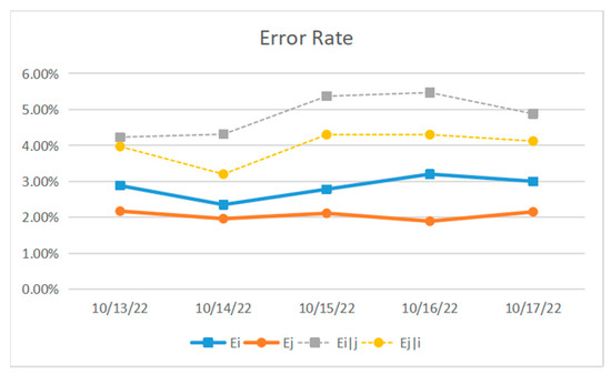
Figure 3.
Daily independent qubit error rate and conditional qubit error rate on IBMQ 5 equipment.
Figure 3 shows that the independent error rates of and on IBMQ5 devices are around 2–3%, and the conditional error rates of and are nearly 4–6%. Figure 3 shows that all conditional qubit error rates are higher than independent qubit error rates, and simultaneous execution of gates CNOT will result in significant crosstalk, resulting in a more than doubled error rate.
Definition 1.
When a single quantum gate or multiple quantum gates execute (simultaneously) in quantum computing devices, the noise generated by unwanted qubit interactions is called crosstalk.
Crosstalk presents two main risks. One is to decrease the accuracy of quantum gate execution, and the other is to increase the global impact of local quantum gates. In many leading architectures, crosstalk has been identified as the primary noise type. The interaction of quantum qubits causes crosstalk, especially when multiple quantum gates (instructions) are executed at the same time, as shown in Figure 4a,b. Due to the coupling effect between CNOT (1, 2) and CNOT (7, 8), CNOT (3, 4), and CNOT (5, 6). There is crosstalk between them.
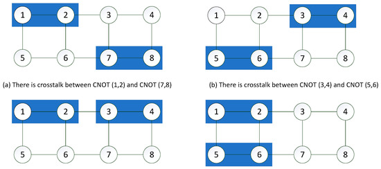
Figure 4.
Crosstalk and high crosstalk.
When the crosstalk significantly affects the operational error rate of the quantum gate, it is called high crosstalk. In this paper, high crosstalk is referred to be the unintentional coupling between two adjacent parallel CNOT gates, as shown in Figure 4c,d.
3.3. Scheduling Strategy for Solving Crosstalk
This paper proposes a method of multiple instruction exchange rules and inserting time stakes to update the occupied state of qubits to solve the problem of high crosstalk. This method can separate double quantum gates with high crosstalk and reduce crosstalk from the standpoint of scheduling strategy.
4. Instruction Exchange Rules
Previous research has shown that separating quantum gates with high crosstalk and breaking the execution order between quantum gates can reduce the impact of crosstalk on the fidelity of quantum circuits, but previous research has only focused on a few quantum gates. This paper classifies the majority of the quantum gates in the executable quantum gate library on quantum computing devices and proposes the corresponding double-instruction exchange rules and multi-instruction exchange rules, which can separate most double quantum gates with high crosstalk at the logic quantum circuit level, effectively alleviating crosstalk.
4.1. Double Instruction Exchange Rules
4.1.1. Partition of Gate Sets under Exchange Rules
On NISQ computing equipment, there are numerous executable quantum gates. We examine the majority of quantum gates used in quantum computing equipment including the following single quantum gates: gate, gate, gate, gate, gate, gate and gate; revolving quantum gates: gate, gate, gate, gate, and gate; double quantum gate: CNOT gate. As shown in Table 6, divide the above gates into gate sets.
Table 6.
Partition of quantum gate set.
4.1.2. Double Exchange Rule
Previous research proposed a set of generalized exchange rules for some quantum gates; however, there are many executable quantum gates on quantum computing devices, and the generalized exchange rules only apply to a subset of them. As shown in Figure 5, this paper proposes a double instruction exchange rule for most executable quantum gates.
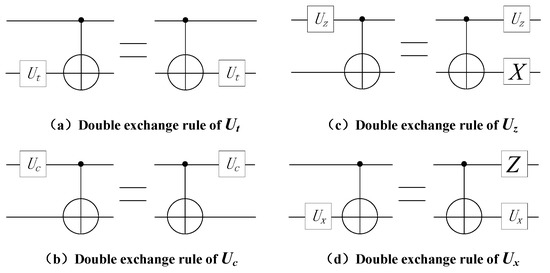
Figure 5.
Double instruction exchange rule.
Rule 1.
If the quantum gate is in the target position of the gate, the position of the two gates can be exchanged, and the quantum circuit before and after the exchange is equivalent. gate includes the gate and the gate.
Proof of Rule 1.
It is proved that if the unitary matrixes of quantum circuits are equal, they are functionally equivalent [18]. Therefore, we calculate the unitary matrix on both sides of the equation. For gate in , The unitary matrix on the left of the equation is (1). The unitary matrix on the right of the equation is (2), because (1) is equals (2). The equation holds. □
In the above formula, is the unit vector, is CNOT gate, and is the tensor product.
Rule 2.
If the quantum gate is in the control position of the gate, the position of the two gates can be exchanged, and the quantum circuit before and after the exchange is equivalent. includes gate, gate, gate, gate, gate, gate and gate.
Proof o Rule 2.
For gate in , the unitary matrix on the left side of the equation is the left side of (3). The unitary matrix on the left side of the equation is the left side of (3). Because their unitary matrices are equal, the equation holds. □
Rule 3.
If the quantum gate is in the control position of the gate, after adding the quantum gate to the target position of the gate, the positions of gate, gate, and gate can be exchanged, and the quantum circuits before and after the exchange are equivalent. includes gate and gate.
Proof of Rule 3.
For gate in , the unitary matrix on the left side of the equation is the left side of (4), The unitary matrix on the left side of the equation is the left side of (4). Because their unitary matrices are equal, the equation holds. □
Rule 4.
If the quantum gate is in the target position of the gate, after adding the quantum gate to the control position of the gate, the positions of the gate, gate, and the gate can be exchanged, and the quantum circuits before and after the exchange are equivalent. gate includes gate and gate.
Proof of Rule 4.
For gate in , the unitary matrix on the left side of the equation is the left side of (5). The unitary matrix on the left side of the equation is the left side of (5). Because their unitary matrices are equal, the equation holds. □
4.1.3. Double Instruction Exchange Rules Reduce Crosstalk
The main source of crosstalk is the simultaneous execution of gates. As illustrated in Figure 6, instructions with high crosstalk can be separated through the double instruction exchange rule, reducing crosstalk.
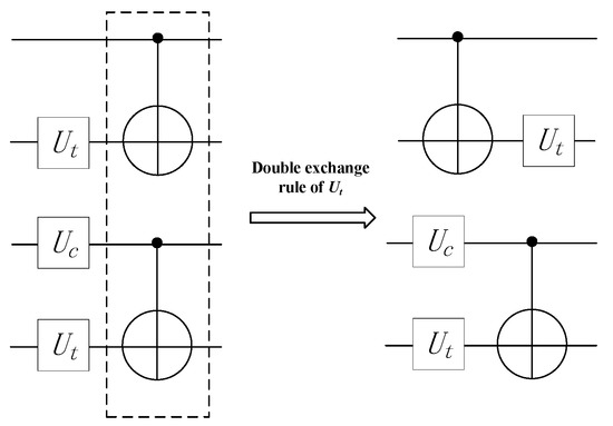
Figure 6.
Double exchange rule reduces crosstalk.
4.2. Multiple Instruction Exchange Rules
The double instruction exchange rule can alleviate crosstalk caused by a pair of gates executing simultaneously, but it cannot eliminate crosstalk caused by multiple gates running concurrently, as shown in Figure 7.
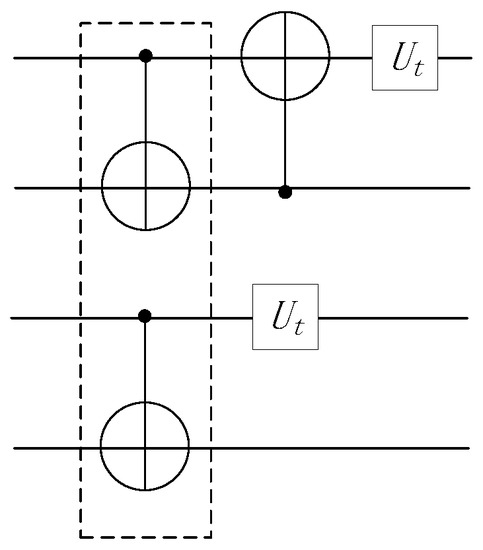
Figure 7.
Crosstalk problem that cannot be solved by double exchange rules.
To solve the problem of crosstalk caused by multiple gates executing in parallel, which cannot be solved by double instruction exchange rules, this paper puts forward multiple instruction exchange rules to reduce crosstalk. On lines with high crosstalk caused by multiple gates executing in parallel, separating the gates with high crosstalk according to multiple instruction exchange rules can reduce the influence of crosstalk on quantum circuits. The multiple instruction exchange rules are shown in Figure 8.
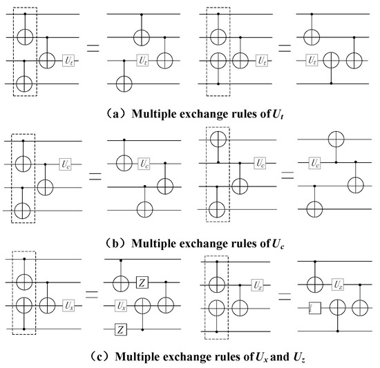
Figure 8.
Multiple instruction exchange rules.
Rule 5.
Among the multiple , if the quantum gate is at the target position of the last or the quantum gate is at the control position of the last , the position of the last and / can be exchanged, and the with crosstalk in the previous layer can be separated to obtain an equivalent circuit with reduced crosstalk, as shown in Figure 8a,b.
Proof of Rule 5.
It is proved that if the unitary matrixes of quantum circuits are equal, they are functionally equivalent. Therefore, we calculate the unitary matrix on both sides of the equation. For gate, the unitary matrix on the left side of the equation is the left side of (6). The unitary matrix on the left side of the equation is the left side of (6). Because their unitary matrices are equal, the equation holds. □
In the above formula, is the unit vector, is CNOT gate, and is the tensor product.
Rule 6.
Among the multiple , if the quantum gate is at the target position of the last or the quantum gate is at the control position of the last , the position of the last and / can be exchanged, and the with crosstalk in the previous layer can be separated to obtain an equivalent circuit with reduced crosstalk, as shown in Figure 8c.
Proof of Rule 6.
For gate, the unitary matrix on the left side of the equation is the left side of (7). The unitary matrix on the left side of the equation is the left side of (7). Because their unitary matrices are equal, the equation holds. □
5. An Update Algorithm of Qubit Occupation State Based on Inserting Time Stake
During the compilation of quantum programs, double instruction exchange rules and multiple instruction exchange rules can preliminarily separate quantum gates with high crosstalk and reduce the influence of crosstalk on quantum circuits.
However, the gates after preliminary separation can still be executed at the same time for some time in the actual quantum computing equipment execution process, and the high crosstalk cannot be completely reduced. To address the aforementioned issues, this paper proposes a method for updating the qubit occupation state by inserting time stakes, summarizes the durations of various quantum gates on NISQ computing equipment, inserts time stakes into quantum circuits based on the durations, and completely separates the simultaneous execution time with adjacent to reduce crosstalk.
5.1. Duration of Different Quantum Gates on Quantum Devices
Previous research on quantum circuit optimization assumed that different quantum gates were executed at the same time, but the execution times of different quantum gates in actual quantum computing devices were different [14]. As shown in Table 7, this paper summarizes the durations of various quantum gates on several NISQ computing devices.
Table 7.
Duration of different quantum gates on quantum computing devices.
The data in Table 7 show that the duration of double quantum gates on different quantum computing devices is approximately twice that of single quantum gates. The duration of single quantum gates is set at one execution time cycle, and the duration of double quantum gates is set at two execution time cycles, according to the data in Table 8. Figure 9 depicts the effect of varying the duration on crosstalk.
Table 8.
Quantum gate stratification in dependency graph.
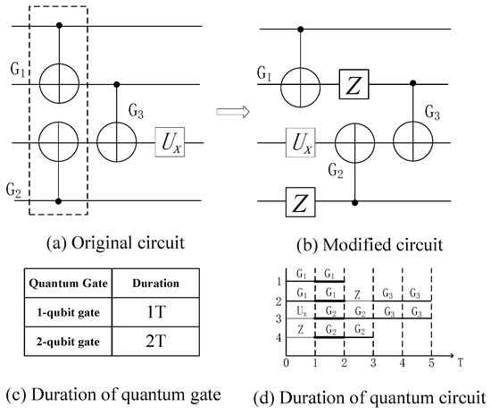
Figure 9.
Influence of duration setting on crosstalk.
In Figure 9a, the simultaneous execution of quantum gates and will result in significant crosstalk. Assuming that all quantum gates have a one-cycle duration, high crosstalk gates can be separated using multiple exchange rules; Figure 9b shows the equivalent quantum circuit obtained using multiple exchange rules, and Figure 9d shows the execution time of the quantum circuit on a real quantum computing device. The two quantum gates are executed simultaneously with one execution time cycle during the first and second time periods, and there is significant crosstalk.
5.2. Dependency GRAPH
The gates in the quantum circuit do not exist independently, and a double quantum gate occupying qubits and can only be executed after all previous double quantum gates have been executed, which is called depend on [28]. Traverse the whole quantum circuit, and construct a directed acyclic graph (DAG) according to this dependency, called relational dependency graph [29], to represent the dependency between two quantum gates in the quantum circuit. Its time complexity is . The single quantum gate is not considered in the relation dependence graph because it can be executed on one qubit alone and will not have dependence on other qubits.
An example is shown in Figure 10. Each node in the dependency graph represents a 2-qubit quantum gate , and each directed edge represents the dependency of one 2-qubit quantum gate to another.
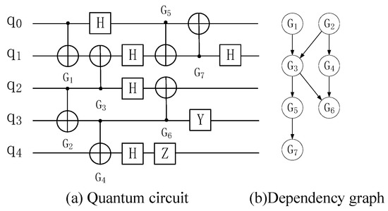
Figure 10.
Dependency graph and layers.
There are nodes with the degree of penetration of 0 in the dependency graph, which are recorded as . Delete all nodes and directed edges in to obtain the second layer . Traverse the whole quantum circuit in turn to obtain the layers of all quantum gates, as shown in Table 8.
5.3. Insert Time Stake
Definition 2.
For a double quantum gate , the empty gate that occupies the adjacent qubits of the quantum gate for two execution periods and is used to update the occupied state of qubits is called a time stake, and its symbol is . The time stake indicates that the qubit and cannot be occupied by other double quantum gates in two execution time cycles until the time stake is completed and the qubits are released from the occupied stake.
A qubit cannot execute multiple quantum gates simultaneously in one time period; only one quantum gate can be executed at most [30]. If a quantum gate occupies a qubit for a certain period of time , it is said that the qubit is in the occupied state for that period of time . If other quantum gates want to apply to use the qubit, they need to wait for the qubit’s occupied state to be released.
The simultaneous execution of adjacent gates on a quantum circuit is the main cause of high crosstalk. Double exchange rules and multiple exchange rules can separate some gates with high crosstalk, but when they are executed on actual quantum computing devices, the adjacent gates still execute simultaneously in some time periods due to the different durations of different quantum gates.
For gate executed on qubits and , it takes two units of time periods. If another gate is executed by adjacent qubits or in these two units of time periods, it will cause high crosstalk.
In order to solve the above problems, this paper sets a time stake for each double quantum gate according to the layers of quantum gates in the relational dependency graph and separates the double quantum gates with high crosstalk by the occupation state of qubits. Traverse each double quantum gate in the Figure 10 quantum gate hierarchy and set a corresponding time post for it. A new layer of quantum gate, shown in Table 9, is obtained.
Table 9.
Quantum gate layering inserted into time pile.
The hierarchical algorithm for obtaining quantum gates with time stakes by inserting time stakes into relational dependency graphs is as follows (Algorithm 1):
| Algorithm 1: Insert time stakes to construct door sets | ||
| Input: Dependency diagram corresponding to quantum circuit: | ||
| Output: a hierarchical door set with time stakes. | ||
| 1 | ← 1, , | |
| 2 | For each do | |
| 3 | If then | |
| 4 | ← | |
| 5 | ← | |
| 6 | ← | |
| 7 | ← | |
| 8 | ←1+1 | |
| 9 | For each do | |
| 10 | For each do | |
| 11 | ← | |
| 12 | ← | |
| 13 | Return | |
5.4. Quantum Qubit State Update
The layered quantum gate after inserting the time stake completely separates the double quantum gate with high crosstalk, but the time stake is not an executable gate which cannot be directly executed on qubits and needs to be represented by the occupied state of qubits. For a qubit , if it is occupied by two quantum gates and successively, it takes two units of time to execute the quantum gate. It is said that the qubit is occupied in these two units of time, and it is noted that , and other double quantum gates cannot call the qubit in these two units of time.
According to the implementation of the quantum gate, the qubit state is constantly updated. As shown in Formula (8), before executing the double qubit gate and the corresponding time stake, the state of the qubits to be occupied must be updated.
is the current execution time of the quantum computing device, which represents a unit execution time cycle. Formula (8) indicates that the will not be released from the occupied state until the current execution time of the quantum computing device equals and can be occupied by other double quantum gates.
After inserting the time stake, according to the layered quantum gate, all the double quantum gates and the time stakes are traversed in turn, and a new quantum gate is inserted according to the updated state of qubits so as to construct a new quantum circuit equivalent to the previous circuit. The quantum circuit effectively separates the gates with high crosstalk by using the time stakes insertion and the updated state of qubits. The quantum qubit occupancy state update algorithm is as follows (Algorithm 2):
| Algorithm 2: Qubit occupation status update | ||
| Input: door set with time pile hierarchy | ||
| Output: reconstructed quantum circuit | ||
| 1 | , | |
| 2 | For each do | |
| 3 | If ← 0 then | |
| 4 | For each do | |
| 5 | For each do | |
| 6 | ← | |
| 7 | ← | |
| 8 | ← | |
| 9 | ||
| 10 | Return | |
Figure 11 shows the equivalent circuit diagram of the quantum circuit in Figure 10a after the qubit occupation state is updated. Figure 12 shows the total execution time of two quantum circuits on real quantum computing devices and the time period of crosstalk.
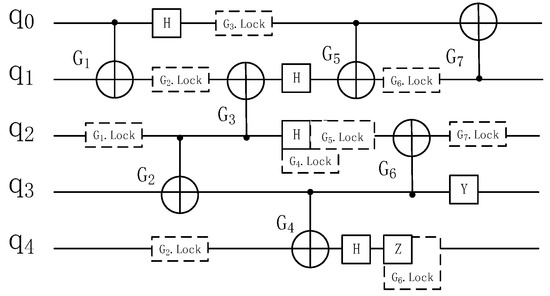
Figure 11.
Quantum circuit after inserting time stake.
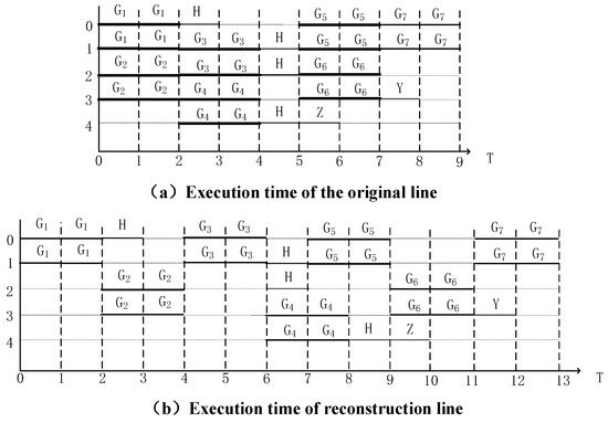
Figure 12.
Crosstalk and execution time after inserting time stake.
Figure 12 shows that three pairs of gates in the initial circuit will produce high crosstalk, which takes up six units of time cycles, and the execution time of the whole circuit is nine units of time cycles. The high crosstalk of the circuit after inserting the time stake takes up zero units of time cycles, and the execution time of the whole circuit is thirteen units of time cycles.
Previous studies have proved that the depth that can be increased by reducing a high crosstalk line is about ten units of time cycles [12]. Compared with the prior research [9], the method of inserting time stakes according to the duration of doors proposed in this paper separates most high crosstalk doors on the basis of a small increase in depth, effectively reducing the influence of crosstalk.
6. Experiment Result and Analysis
In this section, the crosstalk mitigation effect of the proposed method will be evaluated and analyzed.
6.1. Experiment Setup
The methods mentioned in this paper are all programmed in Python, in which we used the qiskit toolkit. The experimental environment CPU is an Intel (R) Core (TM) i7-8750H CPU @ 2.20 GHz, with 16GB of memory and the Windows S11 operating system. The benchmark circuit is selected from the RevLib benchmark data set [31] to carry out the exchange rules and circuit reconfiguration experiments.
In order to obtain a more accurate quantum circuit execution result, this paper uses the topological structure and parameter information of real quantum computing devices IBMQ Manila and Belem [32] to perform the experiment and uses IBMQ API [33,34] to instantly obtain the calibration data of real quantum computing devices, including quantum gate error rate and duration. The duration of all single quantum gates is set to one unit of time cycle, and the duration of double quantum gates is set to two units of time cycles.
6.2. Index
In this paper, the topology and parameter information of IBMQ Manila and Belem are used to evaluate the proposed algorithm. Using independent error rate and conditional error rate to simulate gate error. Each benchmark test is performed on IBMQ Manila and Belem, and 6000 experiments are performed on real quantum computing devices for each benchmark circuit. Take the number of successful experiments as an indicator to measure fidelity. This is a commonly used measure in previous experimental studies [12,35,36].
For example, a fidelity of 0.35 means that the number of expected results is 2100 among the results of 6000 experiments, accounting for 35% of the total number of experiments; the ideal fidelity is 1, which is the final result that quantum computing wants to achieve on real quantum computing devices in the future; and the quantum computing is completely correct.
6.3. Analysis of Fidelity Experimental Results
The Sabre [37] method proposed by G Li et al. is an advanced algorithm at present. We compare the fidelity of Sabre and the method proposed in this paper on Manila and Belem. Figure 13 and Figure 14 show the fidelity of the proposed method and Sabre in all benchmark tests.
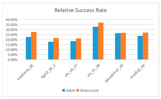
Figure 13.
IBM Manila.
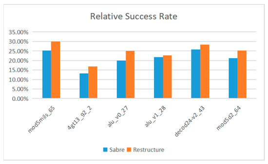
Figure 14.
IBM Belem.
The formula for calculating the average optimization rate is shown in Formula (9), where is the average optimization rate, represents the number of successful quantum circuit experiments obtained by our proposed method, and represents the number of successful quantum circuit experiments obtained by using the Saber algorithm. represents the total number of tests.
On IBMQ Manila, the average optimization rate of the proposed method is 14.47%. On IBMQ Belem, the average optimization rate of the proposed method is 17.46%. The average optimization rate on the two devices is 15.97%.
6.4. Analysis of Experimental Results of Crosstalk Mitigation
Due to the defects in the hardware of quantum computing devices, all kinds of noise will be generated when the quantum computing devices execute, which makes the fidelity of quantum computing devices fail to reach the ideal state. High crosstalk is a major source of noise [12,23]. The method proposed in this paper can separate the double quantum gates with high crosstalk before the quantum computing equipment is executed and reduce crosstalk. Figure 15 shows crosstalk mitigation information for multiple reference circuits. The results show that the proposed method can effectively reduce the crosstalk in the line, and the average optimization rate reaches 79.78%.
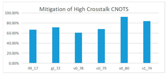
Figure 15.
Reduction in high crosstalk in the quantum circuit.
7. Conclusions
Crosstalk is the primary source of noise in NISQ quantum computing equipment, and the simultaneous parallel execution of multiple double quantum gates is the primary cause of high crosstalk, which destroys quantum states on qubits, resulting in erroneous quantum circuit execution results. This paper proposes a method for updating the qubit occupation state using multiple exchange rules and inserting time stakes. Double quantum gates with high crosstalk are separated by multiple exchange rules and time stakes based on the duration of different quantum gates. Experiments show that the proposed method is very effective in reducing high crosstalk in quantum circuits and that, when compared to the prior art, the proposed method improves fidelity by 15.97% on average.
A quantum algorithm needs to go through several stages, from generation to actual operation. The process is as follows: conversion of quantum algorithms into logical quantum circuits; qubit mapping; quantum circuit routing; and quantum circuit scheduling. This study aims to mitigate crosstalk in logic quantum circuits and quantum circuit scheduling. In the future, we can also consider mitigating crosstalk in other processes to achieve better quantum circuit operation.
Author Contributions
Conceptualization, R.L. and Z.G.; methodology, R.L.; software, R.L.; validation, R.L. and Z.G.; formal analysis, R.L.; investigation, R.L.; resources, R.L.; data curation, R.L.; writing—original draft preparation, S.F.; writing—review and editing, X.C. and P.Z.; supervision, R.L. All authors have read and agreed to the published version of the manuscript.
Funding
This work is supported by the National Natural Science Foundation of China (No. 62072259), the Jiangsu Province Natural Science Foundation of China under Grant (BK20151274), the PhD Start-up Fund of Nantong University under Grant (No. 23B03), the Natural Science Foundation of Jiangsu Province under Grant (BK20221411).
Institutional Review Board Statement
Not applicable.
Informed Consent Statement
Not applicable.
Data Availability Statement
The data used to support the findings of this study will be available from the author upon request.
Conflicts of Interest
The authors declare no conflict of interest.
References
- Yan, F.; Venegas-Andraca, S.E.; Hirota, K. Toward implementing efficient image processing algorithms on quantum computers. Soft Comput. 2022, 1–13. [Google Scholar] [CrossRef]
- Mavroeidis, V.; Vishi, K.; Zych, M.D.; Jøsang, A. The impact of quantum computing on present cryptography. arXiv 2018, arXiv:1804.00200. [Google Scholar] [CrossRef]
- Dunjko, V.; Briegel, H.J. Machine learning & artificial intelligence in the quantum domain: A review of recent progress. Rep. Prog. Phys. 2018, 81, 074001. [Google Scholar] [PubMed]
- Boyer, M.; Brassard, G.; Høyer, P.; Tapp, A. Tight Bounds on Quantum Searching. Fortschr. Der Phys. 1998, 46, 493–505. [Google Scholar] [CrossRef]
- Tannu, S.S.; Qureshi, M.K. Not all qubits are created equal: A case for variability-aware policies for NISQ-era quantum computers. In Proceedings of the Twenty-Fourth International Conference on Architectural Support for Programming Languages and Operating Systems, Providence, RI, USA, 13–17 April 2019. [Google Scholar]
- Yasunari, S.; Endo, S.; Tokunaga, Y. Quantum error mitigation for fault-tolerant quantum computing. APS March Meet. Abstr. 2021, 2021, F32-010. [Google Scholar]
- Reshma, V.G.; Mohanan, P.V. Quantum dots: Applications and safety consequences. J. Lumin. 2019, 205, 287–298. [Google Scholar] [CrossRef]
- Gidwani, B.; Sahu, V.; Shukla, S.S.; Pandey, R.; Joshi, V.; Jain, V.K.; Vyas, A. Quantum dots: Prospectives, toxicity, advances and applications. J. Drug Deliv. Sci. Technol. 2021, 61, 102308. [Google Scholar] [CrossRef]
- Murali, P.; McKay, D.C.; Martonosi, M.; Javadi-Abhari, A. Software mitigation of crosstalk on noisy intermediate-scale quantum computers. In Proceedings of the Twenty-Fifth International Conference on Architectural Support for Programming Languages and Operating Systems, Lausanne, Switzerland, 16–20 March 2020. [Google Scholar]
- Wei, K.X.; Magesan, E.; Lauer, I.; Srinivasan, S.; Bogorin, D.F.; Carnevale, S.; Keefe, G.A.; Kim, Y.; Klaus, D.; Landers, W.; et al. Quantum crosstalk cancellation for fast entangling gates and improved multi-qubit performance. arXiv 2021, arXiv:2106.00675. [Google Scholar]
- Halama, S.; Dubielzig, T.; Orlowski, N.; Torkzaban, C.; Ospelkaus, C. Real-time capable CCD-based individual trapped-ion qubit measurement. arXiv 2022, arXiv:2204.09112. [Google Scholar]
- Xie, L.; Zhai, J.; Zheng, W. Mitigating Crosstalk in Quantum Computers through Commutativity-Based Instruction Reordering. In Proceedings of the 2021 58th ACM/IEEE Design Automation Conference (DAC), San Francisco, CA, USA, 5–9 December 2021; IEEE: New York, NY, USA, 2021. [Google Scholar]
- Sanders, Y.R.; Wallman, J.J.; Sanders, B.C. Bounding quantum gate error rate based on reported average fidelity. New J. Phys. 2015, 18, 012002. [Google Scholar] [CrossRef]
- Deng, H.; Zhang, Y.; Li, Q. Codar: A contextual duration-aware qubit mapping for various nisq devices. In Proceedings of the 2020 57th ACM/IEEE Design Automation Conference (DAC), San Francisco, CA, USA, 20–24 July 2020; IEEE: New York, NY, USA, 2020. [Google Scholar]
- Neergaard-Nielsen, J.S.; Takeuchi, M.; Wakui, K.; Takahashi, H.; Hayasaka, K.; Takeoka, M.; Sasaki, M. Optical continuous-variable qubit. Phys. Rev. Lett. 2010, 105, 053602. [Google Scholar] [CrossRef] [PubMed]
- Li, C.K.; Roberts, R.; Yin, X. Decomposition of unitary matrices and quantum gates. Int. J. Quantum Inf. 2013, 11, 1350015. [Google Scholar] [CrossRef]
- Chiribella, G.; D’Ariano, G.M.; Perinotti, P. Quantum circuit architecture. Phys. Rev. Lett. 2008, 101, 060401. [Google Scholar] [CrossRef]
- Möttönen, M.; Vartiainen, J.J.; Bergholm, V.; Salomaa, M.M. Quantum circuits for general multiqubit gates. Phys. Rev. Lett. 2004, 93, 130502. [Google Scholar] [CrossRef]
- Mundada, P.; Zhang, G.; Hazard, T.; Houck, A. Suppression of qubit crosstalk in a tunable coupling superconducting circuit. Phys. Rev. Appl. 2019, 12, 054023. [Google Scholar] [CrossRef]
- Mitchell, B.K.; Naik, R.K.; Morvan, A.; Hashim, A.; Kreikebaum, J.M.; Marinelli, B.; Lavrijsen, W.; Nowrouzi, K.; Santiago, D.I.; Siddiqi, I. Hardware-efficient microwave-activated tunable coupling between superconducting qubits. Phys. Rev. Lett. 2021, 127, 200502. [Google Scholar] [CrossRef]
- Brink, M.; Chow, J.M.; Hertzberg, J.; Magesan, E.; Rosenblatt, S. Device challenges for near term superconducting quantum processors: Frequency collisions. In Proceedings of the 2018 IEEE International Electron Devices Meeting (IEDM), San Francisco, CA, USA, 1–5 December 2018; IEEE: New York, NY, USA, 2018. [Google Scholar]
- Morvan, A.; Chen, L.; Larson, J.M.; Santiago, D.I.; Siddiqi, I. Optimizing frequency allocation for fixed-frequency superconducting quantum processors. Phys. Rev. Res. 2022, 4, 023079. [Google Scholar] [CrossRef]
- Wei, K.X.; Magesan, E.; Lauer, I.; Srinivasan, S.; Bogorin, D.F.; Carnevale, S.; Keefe, G.A.; Kim, Y.; Klaus, D.; Landers, W.; et al. Hamiltonian engineering with multicolor drives for fast entangling gates and quantum crosstalk cancellation. Phys. Rev. Lett. 2022, 129, 060501. [Google Scholar] [CrossRef]
- Chamberland, C.; Zhu, G.; Yoder, T.J.; Hertzberg, J.B.; Cross, A.W. Topological and subsystem codes on low-degree graphs with flag qubits. Phys. Rev. X 2020, 10, 011022. [Google Scholar] [CrossRef]
- Harper, R.; Flammia, S.T.; Wallman, J.J. Efficient learning of quantum noise. Nat. Phys. 2020, 16, 1184–1188. [Google Scholar] [CrossRef]
- Knill, E.; Leibfried, D.; Reichle, R.; Britton, J.; Blakestad, R.B.; Jost, J.D.; Langer, C.; Ozeri, R.; Seidelin, S.; Wineland, D.J. Randomized benchmarking of quantum gates. Phys. Rev. A 2008, 77, 012307. [Google Scholar] [CrossRef]
- Magesan, E.; Gambetta, J.M.; Emerson, J. Characterizing quantum gates via randomized benchmarking. Phys. Rev. A 2012, 85, 042311. [Google Scholar] [CrossRef]
- Zhou, X.; Feng, Y.; Li, S. Quantum Circuit Transformation: A Monte Carlo Tree Search Framework. ACM Trans. Des. Autom. Electron. Syst. 2022, 27, 59. [Google Scholar] [CrossRef]
- Cheng, C.Y.; Yang, C.Y.; Wang, R.C.; Kuo, Y.H.; Cheng, H.C. Qubit Mapping Toward Quantum Advantage. arXiv 2022, arXiv:2210.01306. [Google Scholar]
- Li, M.; Guo, F.Q.; Jin, Z.; Yan, L.L.; Liang, E.J.; Su, S.L. Multiple-qubit controlled unitary quantum gate for Rydberg atoms using shortcut to adiabaticity and optimized geometric quantum operations. Phys. Rev. A 2021, 103, 062607. [Google Scholar] [CrossRef]
- Wille, R.; Große, D.; Teuber, L.; Dueck, G.W.; Drechsler, R. RevLib: An online resource for reversible functions and reversible circuits. In Proceedings of the 38th International Symposium on Multiple Valued Logic, Dallas, TX, USA, 22–24 May 2008; pp. 220–225. [Google Scholar]
- IBM Quantum Experience. Available online: https://quantum-computing.ibm.com/ (accessed on 16 December 2021).
- IBM. IBM Quantum Devices. 2018. Available online: https://quantumexperience.ng.bluemix.net/qx/devices (accessed on 16 May 2018).
- IBM. IBM Quantum Experience. 2018. Available online: https://github.com/Qiskit/qiskit-api-py (accessed on 16 November 2018).
- Murali, P.; Baker, J.M.; Javadi-Abhari, A.; Chong, F.T.; Martonosi, M. Noise-Adaptive Compiler Mappings for Noisy Intermediate-Scale Quantum Computers. In Proceedings of the Twenty-Fourth International Conference on Architectural Support for Programming Languages and Operating Systems, Providence, RI, USA, 13–17 April 2019. [Google Scholar] [CrossRef]
- Qureshi, M.; Tannu, S. Quantum Computing and the Design of the Ultimate Accelerator. IEEE Micro 2021, 41, 8–14. [Google Scholar] [CrossRef]
- Li, G.; Ding, Y.; Xie, Y. Tackling the Qubit Mapping Proble-m for NISQ-Era Quantum Devices. arXiv 2018, arXiv:1809.02573.2018. [Google Scholar]


Disclaimer/Publisher’s Note: The statements, opinions and data contained in all publications are solely those of the individual author(s) and contributor(s) and not of MDPI and/or the editor(s). MDPI and/or the editor(s) disclaim responsibility for any injury to people or property resulting from any ideas, methods, instructions or products referred to in the content. |
© 2023 by the authors. Licensee MDPI, Basel, Switzerland. This article is an open access article distributed under the terms and conditions of the Creative Commons Attribution (CC BY) license (https://creativecommons.org/licenses/by/4.0/).