Article

Hyper-Chaotic Color Image Encryption Based on Transformed Zigzag Diffusion and RNA Operation

School of Economic Information Engineering, Southwestern University of Finance and Economics, Chengdu 611130, China
*
Author to whom correspondence should be addressed.
Entropy 2021, 23(3), 361; https://doi.org/10.3390/e23030361
Submission received: 27 January 2021 / Revised: 11 March 2021 / Accepted: 15 March 2021 / Published: 17 March 2021
(This article belongs to the Special Issue Entropy in Image Analysis III)

Abstract

:
With increasing utilization of digital multimedia and the Internet, protection on this digital information from cracks has become a hot topic in the communication field. As a path for protecting digital visual information, image encryption plays a crucial role in modern society. In this paper, a novel six-dimensional (6D) hyper-chaotic encryption scheme with three-dimensional (3D) transformed Zigzag diffusion and RNA operation (HCZRNA) is proposed for color images. For this HCZRNA scheme, four phases are included. First, three pseudo-random matrices are generated from the 6D hyper-chaotic system. Second, plaintext color image would be permuted by using the first pseudo-random matrix to convert to an initial cipher image. Third, the initial cipher image is placed on cube for 3D transformed Zigzag diffusion using the second pseudo-random matrix. Finally, the diffused image is converted to RNA codons array and updated through RNA codons tables, which are generated by codons and the third pseudo-random matrix. After four phases, a cipher image is obtained, and the experimental results show that HCZRNA has high resistance against well-known attacks and it is superior to other schemes.

1. Introduction

Nowadays, rapid developments of Internet and digital technologies have led to tremendous digital multimedia contents transmitting over Internet networks. Thus, protection on the contents of digital data has attracted serious concern from medical, military, and many other areas. Various image encryption methods have emerged by using cryptographic techniques [1,2,3,4]. Although there exists a view that AES is not suitable for image encryption, Zhang recently refuted it by using AES of cipher block chaining mode to encrypt images [5].
The chaos-based encryption method has become one of the most ideal methods, since it has a lot of appropriate characteristics, e.g. high sensitivity on initial conditions, mixing property, ergodicity, complex behavior, etc. [6,7,8]. As a result, a lot of researchers have presented plenty of image encryption schemes with a chaotic system [9,10,11,12,13]. In [14], Askar et al. proposed a chaotic economic map based image encryption method, whose simulation results indicated that the proposed algorithm could successfully encrypt and decrypt the images, and it had a good performance on security tests, except noise attacks analysis. By using a single round based hyper-chaotic system, Shaikh et al. presented a color image encryption method with bi-directional pixel diffusion [15]. Additionally, Li et al. presented a "transforming-scrambling-diffusion” model based color image encryption method with a four-dimensional (4D) hyper-chaotic system, which could convert pixel values to gray format before scrambling [16]. There is no doubt that some of the encryption methods in these chaos-based schemes still have weaknesses to some extent. However, different chaotic systems are neither superior nor inferior each other. A high-dimensional chaotic system has complex chaotic behaviors with high time cost, while a low-dimensional chaotic system is opposite [17,18,19]. Hence, in this paper, a 6D hyper-chaotic system is employed as a pseudo-random numbers sequence generator for more complexity.
Zigzag is a common scrambling operation in image encryption [20,21]. In [22], Li et al. presented a 3D logistic map based color image encryption method with Zigzag scramble; the experiments showed that this method had brute-force attack and statistical attack resistance, but differential attacks analysis was missing. While, Wang et al. proposed a color encryption method with a Zigzag transformation, which could change the start pixel from upper left corner to the other three corners in an image [20]. Next year, Wang et al. [23] presented another image encryption method, which introduced an extended Zigzag confusion for a non-square image. Additionally, in [24], Zhao et al. proposed a novel color image encryption by combining Zigzag map and Hénon map together for permutation. However, these image encryption schemes implement Zigzag scramble on 2D images, which leads to some adjacent values in special positions of the image not being able to be scrambled, and different channels of a color image could not be scrambled, either. On the other hand, some image encryptions transformed 2D image to 3D cube [
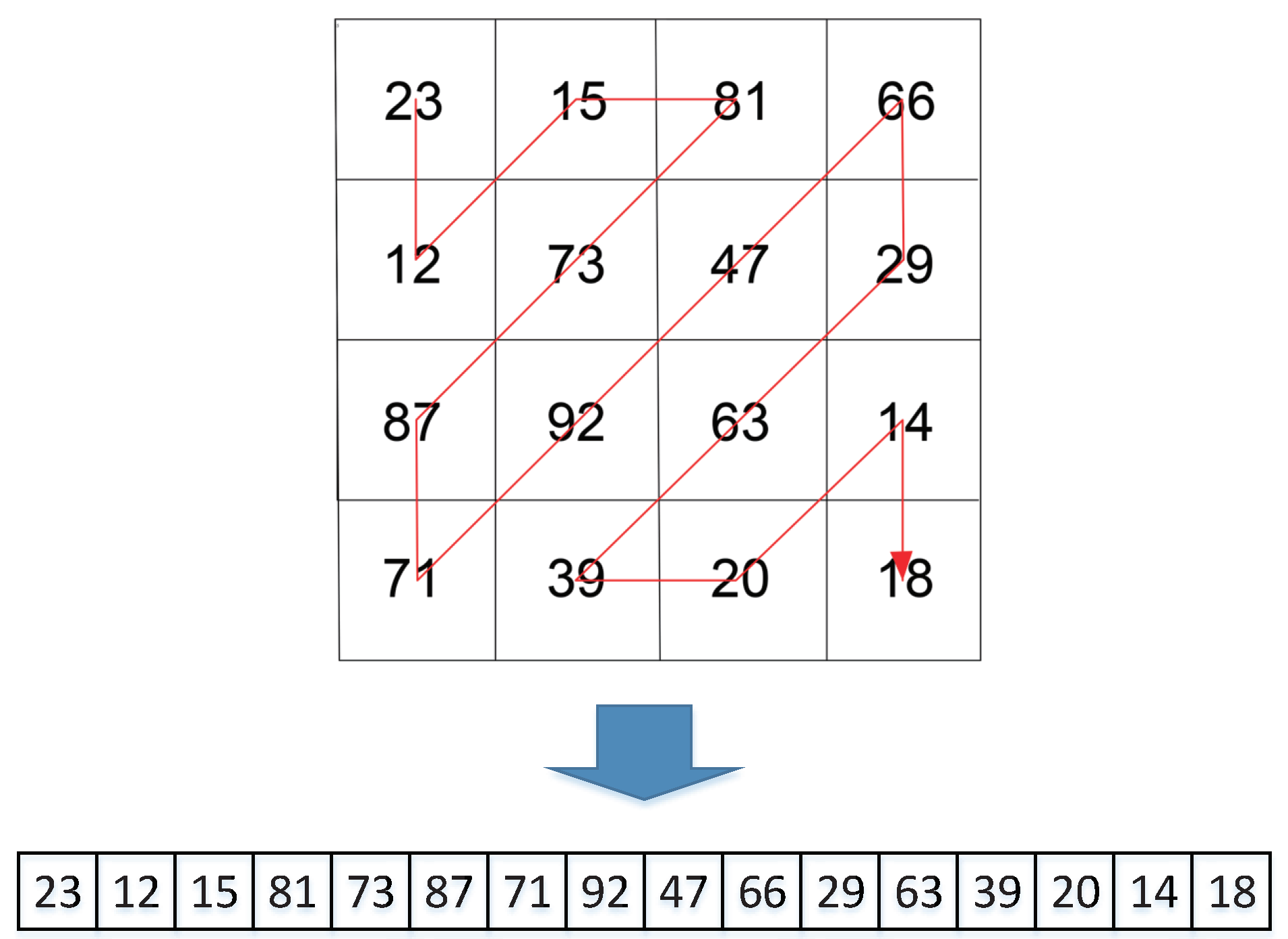
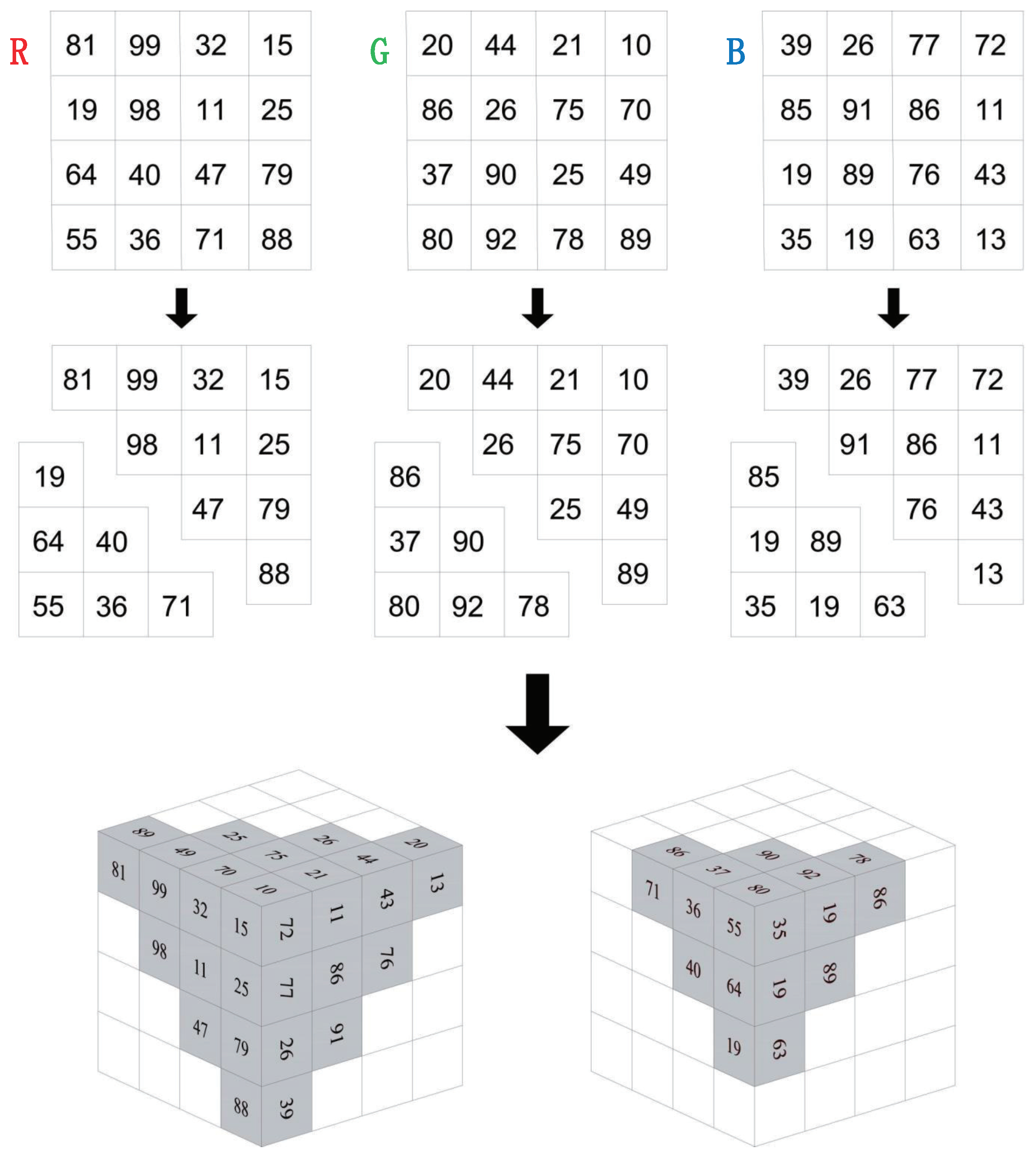
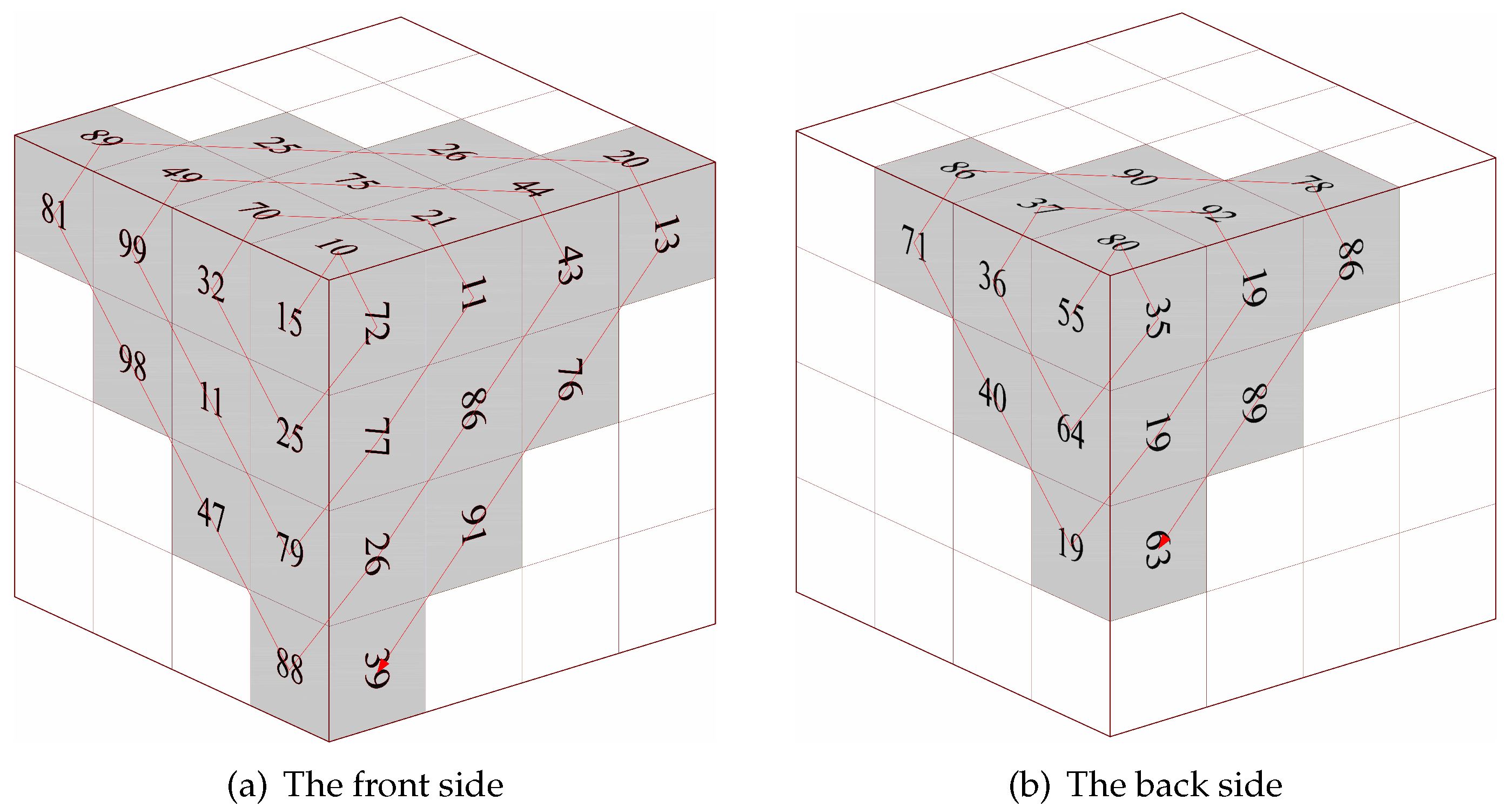
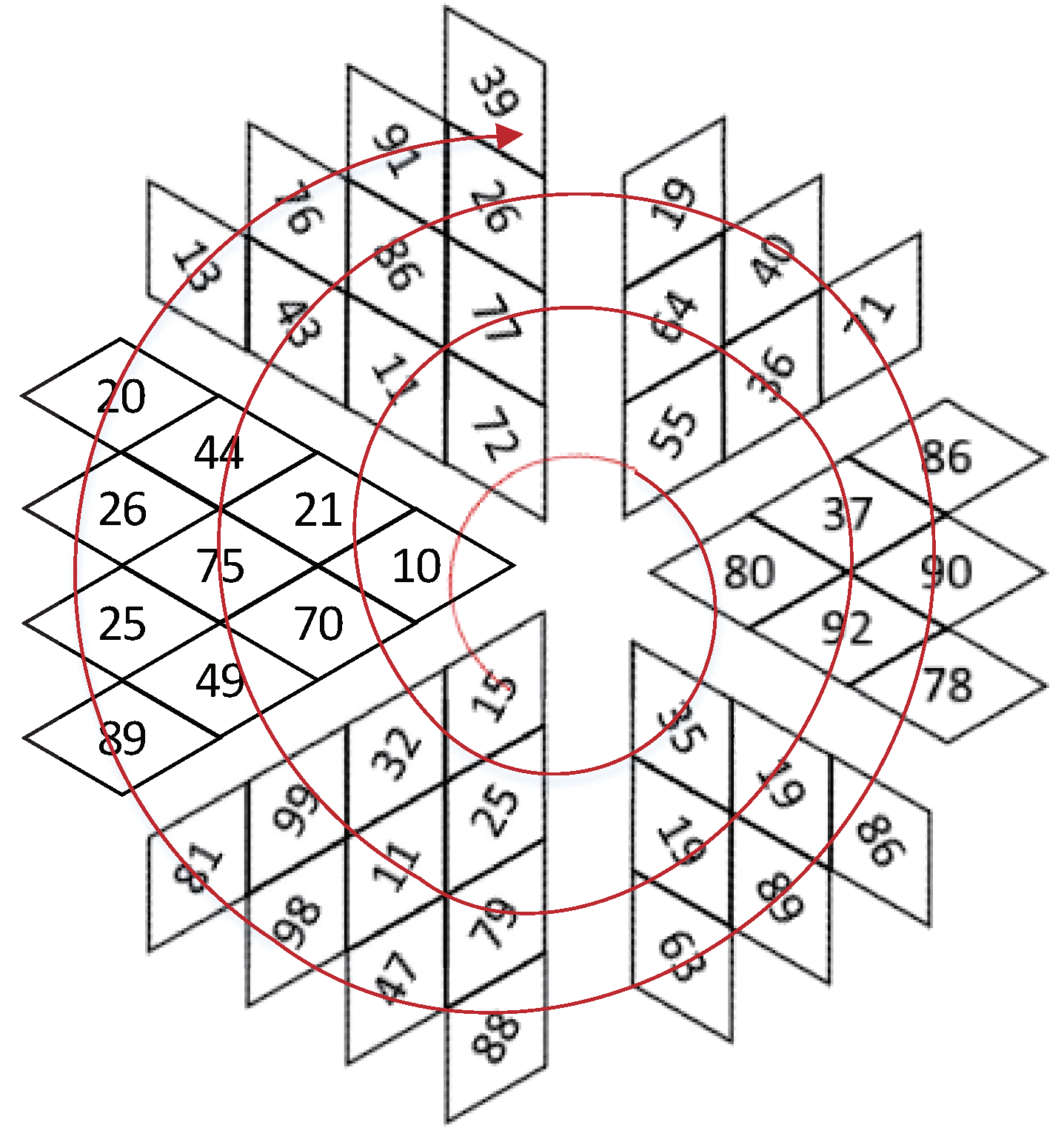
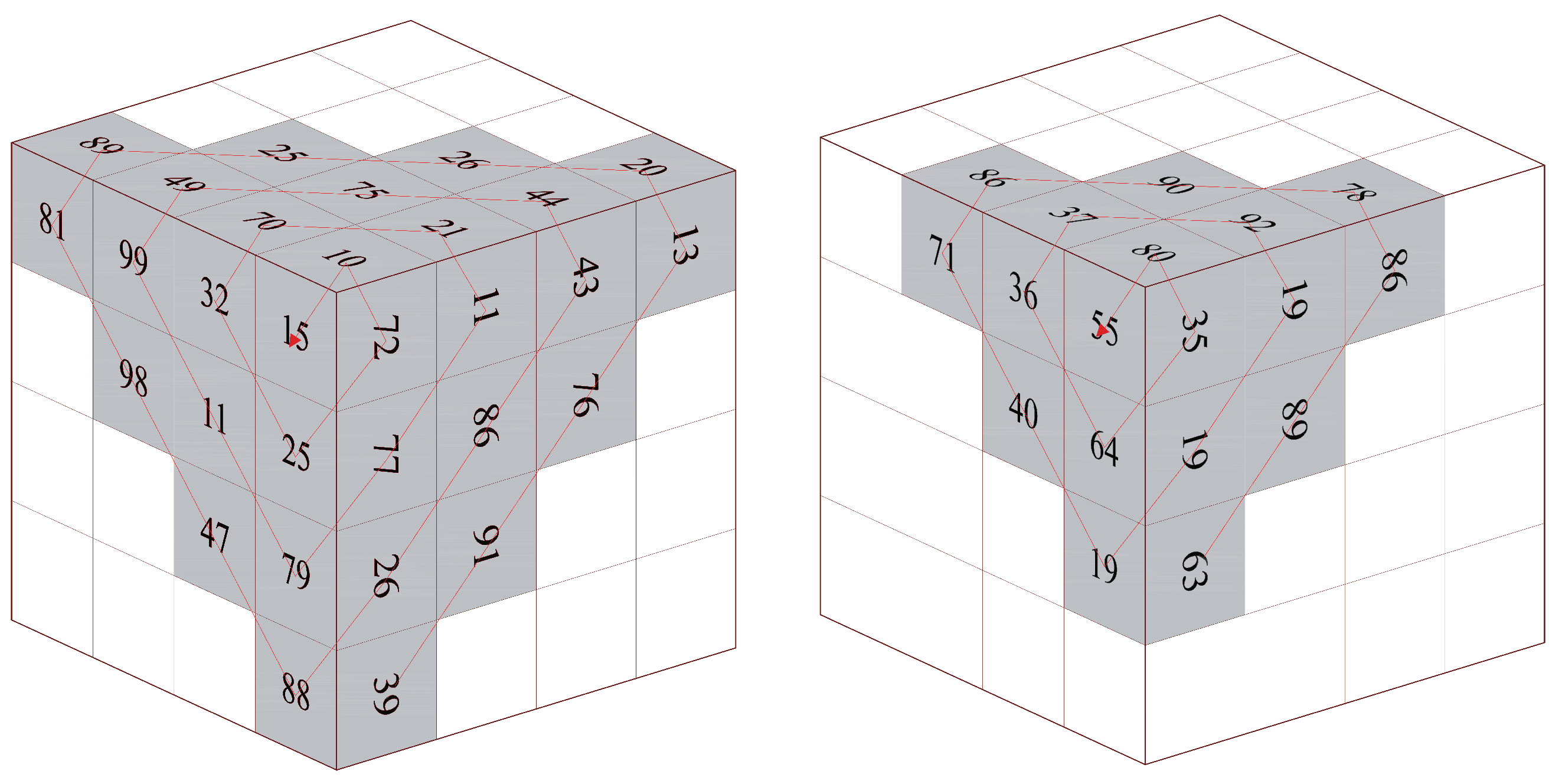
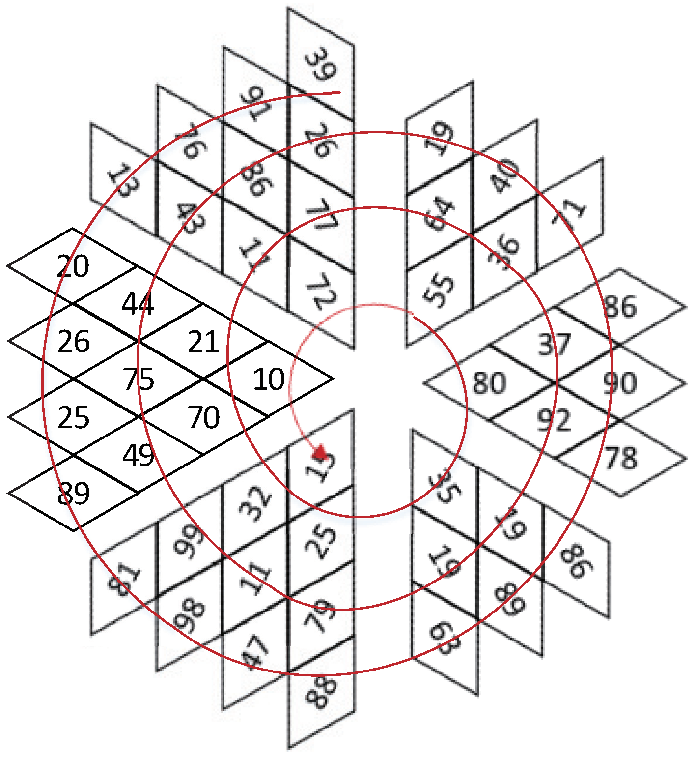
25], which gives out a new encryption inspiration on permutation, but most of them were focused on rotation, but not Zigzag. Therefore, Zigzag is utilized in diffusion on a 3D cube instead of scramble on 2D image to eliminate these drawbacks in this paper.
Deoxyribonucleic acid (DNA), a biological concept, has recently become a popular trend in the image encryption field [26,27]. By using DNA-based techniques, cipher images could obtain competitive entropy, correlation coefficients etc. [4,28,29,30,31]. In [29], Chai et al. presented a new diffusion mechanism that is based on the random numbers that are generated by plaintext image, and incorporated DNA encryption with four-wing hyper-chaotic system. Reference [32] proposed an image encryption method using a spatial map based DNA sequence matrix. In general, the DNA-based encryption mechanism includes two steps: use DNA operation rules to convert pixels of plaintext image to DNA codon matrix and change chaotic sequence to DNA keys to generate cipher image with DNA codon matrix.
While unlike the two strands structure of DNA sequences, Ribonucleic acid (RNA) is a single strand structure. RNA could form double helixes with complementary base pairing. By using this feature, some new image encryption methods have been proposed. In [33], Mahmud et al. presented an image encryption method by combining RNA with Genetic Algorithm (GA) through using a logistic map. In [34], Abbasi et al. employed Chen’s chaotic system to encrypt an image with imperialist competition algorithm and RNA operations. Yadollahi et al. utilized the concepts of DNA and RNA to construct a two-phase image encryption method [35]. While an image encryption method is presented by Wang et al. through using an one-dimensional (1D) chaotic system combined from Logistic and Sine map, extended Zigzag confusion, and RNA operation [23]. However, all of these four schemes focus on gray image encryption. Although there is a color image experiment in [23], it is realized by running the scheme three times in three channels.
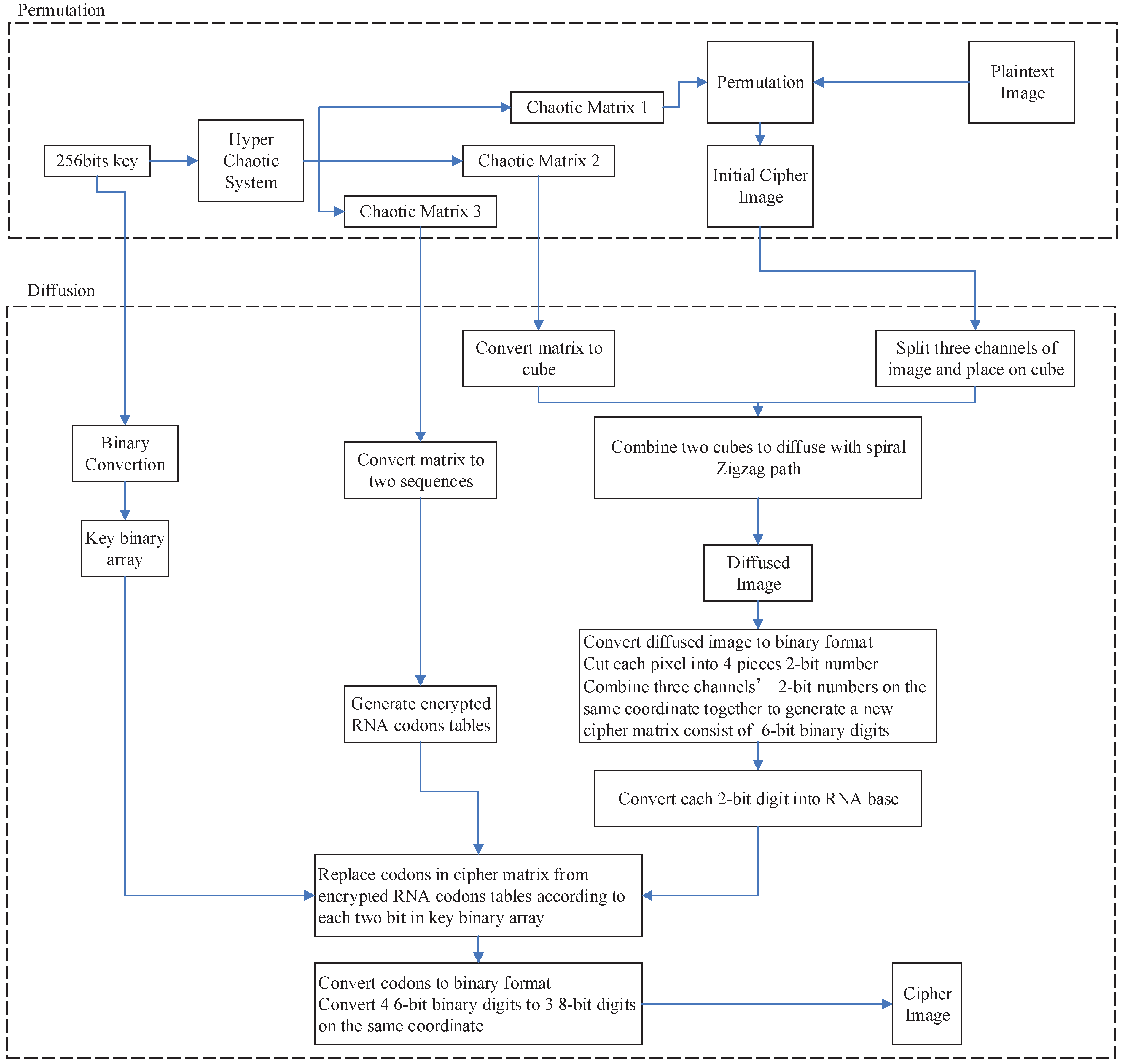
Being motivated by above discussions, a novel color image encryption method, called HCZRNA, is proposed in this paper. At the beginning, a 6D hyper-chaotic system is employed to generate three pseudo-random matrices. Subsequently, one of the pseudo-random matrices is used to permute plaintext color image. Additionally, 3D transformed Zigzag diffusion is implemented on initial cipher image with the second pseudo-random matrix. After diffusion, an RNA operation is used to convert the diffused image to RNA codons array, and update this array through RNA codons tables that are generated by the third pseudo-random matrix. Finally, a cipher image is obtained.
The main contributions of this work is listed as follows:
  • A novel 6D hyper-chaotic system is employed in this paper to produce chaotic matrix for permutation, diffusion, and RNA operation.
  • A new 3D transformed Zigzag diffusion scheme is proposed to encrypt color images.
  • RNA operation is modified specifically for color images.
  • Extensive experiments and analyses demonstrate that the proposed HCZRNA could resist various types of attacks.
The rest of this paper is structured as follows: 
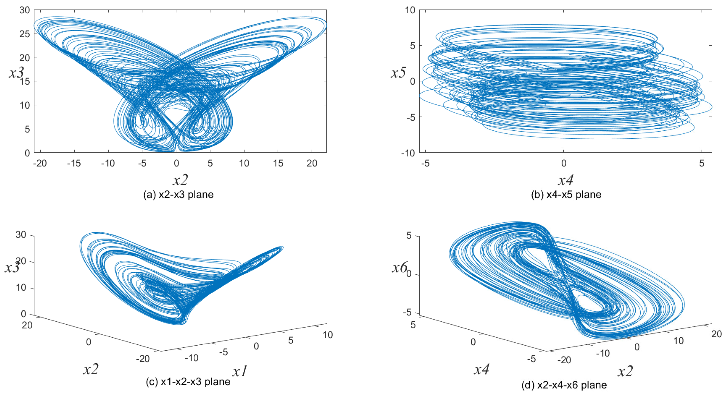
Section 2 introduces the used 6D hyper-chaotic system, 3D Zigzag and RNA. Section 3 presents the HCZRNA scheme and explains how initial values and pseudo-random matrix are generated in detail. Section 4 reports and analyzes the experimental results. Finally, Section 5 concludes this paper.

2. Preliminaries

2.1. The 6D Hyper-Chaotic System

There are a lot of classical chaotic systems, e.g. Sine map, Logistic map, Tent map, etc., which have simple mathematical forms and can be implemented easily. However, they suffer from small key spaces, predictable orbits, limited ranges, etc. Existing research has shown that higher dimensional chaotic systems are much securer for image encryption [36]. Therefore, a novel 6D hyper-chaotic system is employed in this paper for chaotic sequences generation, which could be described as Equation (1) [37].
x ˙ 1 = g ( ω + β x 6 2 ) x 2 a x 1 x ˙ 2 = c x 1 + d x 2 x 1 x 3 + x 5 x ˙ 3 = b x 3 + x 1 2 x ˙ 4 = e x 2 + f x 4 x ˙ 5 = r x 1 x ˙ 6 = x 2
where a , b , c , d , e , f , g , r , ω , and β are controlling parameters, and x i ( i = 1 , 2 , , 6 ) are state variables.
The fourth-order Runge–Kutta method is used to solve this hyper-chaotic system with step size h = 0.001 . We set the controlling parameters as ( a , b , c , d , e , f , g , r , ω , β ) = ( 0.3 , 1.5 , 8.5 , 2 , 1 , 0.1 , 0.9 , 1 , 1 , 0.2 ) and initial state variables as ( x 1 , x 2 , x 3 , x 4 , x 5 , x 6 ) = ( 0.1 , 0.6 , 0.2 , 0.02 , 1 , 0.5 ) ; Figure 1 shows this 6D hyper-chaotic system’s attractors. Its Lyapunov exponents are λ 1 = 7.340 , λ 2 = 0.087 , λ 3 = 0.006 , λ 4 = 0.368 , λ 5 = 1.349 , λ 6 = 67.426 . Since this chaotic system has three positive Lyapunov exponents, its prediction time should be longer than other chaotic systems and it is hard to crack. Besides, this hyper-chaotic system exhibits limit cycles, quasiperiodic, and bursting behavior. Accordingly, it could generate effective a pseudo random sequence. More detailed demonstration could be found in reference [37].

2.2. 3D Transformed Zigzag Diffusion

Zigzag is a scanning method that is used to scramble pixels in image encryption. By scanning and taking a pixel with left upper corner of image, then taking other pixels one-by-one through Zigzag path, the image could be converted to a matrix in a fixed way. Hence, the image’s pixels could be scrambled.
Traditional Zigzag scrambling could only walk through numbers in N × N matrix with a fixed Zigzag path; an example of 4 × 4 matrix is shown in Figure 2. By this fixed path, different channels of color image could not be scrambled with each other. Due to its drawbacks, this paper proposes a novel 3D Zigzag transformation. Using this transformation, each channel of color image would be cut into two triangles through a diagonal line, and be placed on opposite surfaces of a cube, which is illustrated by an example of 4 × 4 × 3 matrix, as shown in Figure 3. Subsequently, diffusion would start from origin vertex of the frontal side of the cube, and walk through every pixels on six surfaces at the front and back side synchronously with spiral Zigzag path, as in Figure 4. For all triangles that are placed on the cube, the order of diffusion is shown in Figure 5. In this way, different channels of color image could be diffused together.

2.3. RNA Operation

RNA is one of the major macromolecules necessary for living organism. RNA has a single strand structure with four nitrogen bases: adnine (A), cytosine (C), guanine (G), and uracil (U). For these four units of RNA, a binary system could be employed for representation, which is shown in Table 1. According to the base pairing rules, four bases of RNA could be coded and constructed into three nucleotides that correspond to one amino acid called codon. Accordingly, there are 64 codons truth table of bases combinations, as shown in Table 2. Assuming that pixels in the image could transfer into six-bits format, a corresponding RNA codon could be found in Table 2.

3. Encryption and Decryption

In this paper, image encryption could be divided into three parts. Firstly, a 6D hyper-chaotic system is employed to generate chaotic matrices for encryption processes. Subsequently, three-dimensional (3D) transformed Zigzag diffusion is implemented on the permuted image. Finally, RNA concept is used for encoding and decoding.

3.1. Encryption Scheme

Suppose that plaintext image has N rows and N columns with RGB channels.
The flowchart of HCZRNA is described in Figure 6, and the specific operations are listed, as follows.

3.1.1. Initial Values Generation

The HCZRNA scheme uses a 256-bit key of different characters against attacks. The 256-bit long security key would be utilized in two parts, which are hyper-chaotic system initial values generation and RNA encryption.
At first, the initial values of hyper-chaotic system should be generated by a security key. Details of initial values generation is performed in three steps:
  • Step 1: divide the secret key K into 32 blocks, which could be expressed as K = { k 1 , k 2 , , k 32 } , each k is a 8-bits number.
  • Step 2: K array that is generated in step 1 is calculated into four intermediate parameters d 1 , d 2 , d 3 , d 4 by Equation (2) with four user-defined constants c 1 , c 2 , c 3 and c 4 .
    d 1 = c 1 + k 1 k 2 k 8 256 d 2 = c 2 + k 9 k 10 k 16 256 d 3 = c 3 + k 17 k 18 k 24 256 d 4 = c 4 + k 25 k 26 k 32 256
    where ⊕ represents bitwise XOR operation.
  • Step 3: The initial values x 1 to x 6 of 6D hyper-chaotic system could be obtained from the 4 intermediate parameters by Equation (3).
    x 1 = ( ( d 1 + d 2 ) × 10 8 ) m o d 256 255 x 2 = ( ( d 2 + d 3 ) × 10 8 ) m o d 256 255 x 3 = ( ( d 3 + d 4 ) × 10 8 ) m o d 256 255 x 4 = ( ( d 1 + d 3 ) × 10 8 ) m o d 256 255 x 5 = ( ( d 1 + d 4 ) × 10 8 ) m o d 256 255 x 6 = ( ( d 2 + d 4 ) × 10 8 ) m o d 256 255
    where m o d means module operation.

3.1.2. Hyper-Chaotic Matrices Generation

With the initial values that are calculated in Section 3.1.1, chaotic matrices could be generated from 6D hyper-chaotic system. In HCZRNA, chaotic matrices would be utilized in three parts, which are permutation, 3D transformed Zigzag diffusion, and RNA operation. Suppose that the plaintext image has N × N × 3 pixels, an N × N × 6 chaotic matrix is needed for permutation, a 2 × N × N × 6 chaotic matrix for Zigzag, and 64 × 6 chaotic matrix for RNA.
Therefore, the 6D hyper-chaotic system utilizes initial values from Equation (3) to iterate for generating a ( 3 × N × N + 64 ) × 6 matrix. Given that i t h iteration’s state values could be described as s i = { x 1 , i , x 2 , i , x 3 , i , x 4 , i , x 5 , i , x 6 , i } , a hyper-chaotic matrix S could be depicted as Equation (4) after all iterations.
S = { s 1 , s 2 , , s M } = x 1 , 1 , x 1 , 2 , , x 1 , M x 2 , 1 , x 2 , 2 , , x 2 , M x 3 , 1 , x 3 , 2 , , x 3 , M x 4 , 1 , x 4 , 2 , , x 4 , M x 5 , 1 , x 5 , 2 , , x 5 , M x 6 , 1 , x 6 , 2 , , x 6 , M 6 × M
where M = 3 × N × N + 64 .
However, the numbers in matrix S are double-precision values, which are suitable for permutation but not for Zigzag and RNA, and color image only has three channels that are smaller than channels of S. Hence, matrix S should be separated into three pieces respectively.
For permutation, a matrix S 1 is calculated from the first N × N part of S by Equation (5).
S 1 = x 1 , 1 + x 2 , 1 , x 1 , 2 + x 2 , 2 , , x 1 , M + x 2 , M x 3 , 1 + x 4 , 1 , x 3 , 2 + x 4 , 2 , , x 3 , M + x 4 , M x 5 , 1 + x 6 , 1 , x 5 , 2 + x 6 , 2 , , x 5 , M + x 6 , M 3 × M
where M = N × N .
While matrix S 2 is cut from s M + 1 to s 3 M in S for 3D transformed Zigzag diffusion. Additionally, because 8-bit integer digits are needed for diffusion, each item x i , j in S 2 should be calculated by Equation (6).
S u p p o s e s i = { x i , ( M + 1 ) , x i , ( M + 2 ) , , x i , 3 M } y i , j = 2 × x i , j + m a x ( s i ) + m i n ( s i ) m a x ( s i ) m i n ( s i ) x i , j = ( ( | y i , j | | y i , j | ) × 10 10 ) m o d 256
where m a x and m i n are maximum and minimum operations.
Matrix S 3 is the last part of matrix S and it is used to sort operation for encrypting RNA codons tables as indexes. Because there only needs two indexes sequences, matrix S 3 should be summarized as Equation (7).
i n d e x 1 = { x 1 , 3 M + 1 + x 2 , 3 M + 1 + x 3 , 3 M + 1 , x 1 , 3 M + 2 + x 2 , 3 M + 2 + x 3 , 3 M + 2 , , x 1 , 3 M + 64 + x 2 , 3 M + 64 + x 3 , 3 M + 64 } i n d e x 2 = { x 4 , 3 M + 1 + x 5 , 3 M + 1 + x 6 , 3 M + 1 , x 4 , 3 M + 2 + x 5 , 3 M + 2 + x 6 , 3 M + 2 , , x 4 , 3 M + 64 + x 5 , 3 M + 64 + x 6 , 3 M + 64 }

3.1.3. Permutation

In this part, matrix S 1 is used to permute plaintext image. At the beginning, each element in S 1 should be allocated to each pixel as index. Hence, an N × N × 3 matrix S 1 is needed to be converted from S 1 by reshaping.
S 1 = r e s h a p e ( S 1 , N , N , 3 )
Afterwards, each pixel in plaintext image has a corresponding index in S 1 at the same coordinate. Combine plaintext image with matrix S 1 , and take another reshaping operation to convert these two matrix into two sequences with a length of N × N × 3 . After sorting S 1 ascendingly with image sequence synchronously, pixels’ orders in plaintext image sequence have been scrambled.
Finally, reshaping the sorted image sequence to an N × N × 3 matrix, the initial cipher image could be generated.

3.1.4. Diffusion

After permutation, a diffusion scheme by 3D Zigzag transformation is proposed, as follows. An initial cipher image would be split and placed on the surfaces of an N × N × 6 cube, termed as P, as described in Section 2.2. Additionally, chaotic matrix S 2 would also be placed on another two N × N × 6 cubes, since diffusion would implement two rounds. For the first N × N × 6 numbers in S 2 , each number would be placed on a cube in order, which could be called cube S C 1 .For the last N × N × 6 numbers in S 2 , cube S C 2 could be generated by the same process.
Subsequently, diffusion would start from origin point of cube P on the front side, and its coordinate is [ 1 , 1 , 1 ] . At each iteration, the pixel’s value C i , j , m is calculated by Equation (9).
C i , j , m = ( P i , j , m ( T + x i , j , m ; 1 ) ) m o d 256
where i , j , m are the coordinates of pixel at the i t h row, j t h column, and m t h side on the cube. T is the previous one diffused pixel’s C value, if i , j , m = 1 , 1 , 1 , T is a user-defined constant. x i , j , m ; 1 is the corresponding coordinate’s value in S C 1 .
For the second round of diffusion, Equation (9) would change to Equation (10).
D i , j , m = ( C i , j , m ( T + x i , j , m ; 2 ) ) m o d 256
where D is result of diffusion, and T is the previous one diffused pixel’s D value, and, if i , j , m = 1 , 1 , 1 , T is the last pixel’s C value after the first round diffusion. While x i , j , m ; 2 is corresponding coordinate’s value in S C 2 .
Through these two round diffusions, D cube is generated. Additionally, recover the D’s N × N × 6 matrix by reversing processes of image splitting and cube placement in Section 2.2. A diffused N × N × 3 matrix D m a t is obtained.

3.1.5. RNA Operation

The encryption from diffused matrix D m a t through RNA operation could be described, as follows:
  • Step 1: RNA operation is initiated from creating two encrypted codons tables, called T 00 and T 01 . In which, T 00 and T 01 are shuffled tables from codons truth, as in Table 2. The shuffle orders are generated according to indexes sequences calculated from Equation (7). After sorting with these two indexes sequences, the original codons truth table could be shuffled to two different encrypted codons tables T 00 and T 01 .
    Subsequently, by the complementary rules of RNA, additional tables T 10 and T 11 could be generated from T 00 and T 01 . Hence, four encrypted codons tables are generated.
  • Step 2: for each element in D m a t , binary number conversion is processed, which is recorded as B.
    B = { b i , j , m } . i , j = 1 , 2 , , N ; m = 1 , 2 , 3
    Each b i , j , m could be expressed as eight binary numbers, which could be depicted as b 0 i , j , m b 1 i , j , m b 2 i , j , m b 3 i , j , m b 4 i , j , m b 5 i , j , m b 6 i , j , m b 7 i , j , m .
  • Step 3: divide b i , j , m into four pieces, each two bits are one piece, which are recorded as:
    b t 1 i , j , m = b 0 i , j , m b 1 i , j , m b t 2 i , j , m = b 2 i , j , m b 3 i , j , m b t 3 i , j , m = b 4 i , j , m b 5 i , j , m b t 4 i , j , m = b 6 i , j , m b 7 i , j , m
    Additionally, combine three channels’ b t s at the same coordinate together:
    b t 1 i , j = b t 1 i , j , 1 b t 1 i , j , 2 b t 1 i , j , 3 b t 2 i , j = b t 2 i , j , 1 b t 2 i , j , 2 b t 2 i , j , 3 b t 3 i , j = b t 3 i , j , 1 b t 3 i , j , 2 b t 3 i , j , 3 b t 4 i , j = b t 4 i , j , 1 b t 4 i , j , 2 b t 4 i , j , 3
    Therefore, each b t i , j has six bits that could transfer to RNA codons according to Table 1. Exchange each two bits in b t s to RNA base one-by-one according to the principle of row priority, b t s could be coded to codons. And put them into a one-dimension sequence B S as Equation (14).
    B S = { b t 1 1 , 1 , b t 2 1 , 1 , b t 3 1 , 1 , b t 4 1 , 1 , b t 1 1 , 2 , b t 2 1 , 2 , , b t 4 2 , 1 , b t 1 2 , 2 , , b t 3 N , N , b t 4 N , N } .
  • Step 4: convert key to binary format. 256-bit key could be changed into a binary sequence B K .
    k e y = [ k e y 0 , k e y 1 , , k e y 31 ] k e y i = k e y i , 0 , k e y i , 1 , , k e y i , 7 B K = [ k e y 1 , 0 , k e y 1 , 1 , , k e y 1 , 7 , k e y 2 , 0 , k e y 2 , 1 , , k e y 31 , 7 ]
    Walk through sequence B S , and find corresponding index i d of each codon in B S from Table 2. For each codon in B S , check 2-bits table number z in sequence B K .
    z = B K n m o d 2048 B K ( n + 1 ) m o d 2048
    where n is the walking times.
    Take the codon T z ( i d ) to replace the origin codon B S ( n ) .
    When iterations termination, an encrypted sequence is generated.
  • Step 5: decode each base in encrypted sequence B S to binary format by Table 1, put all of the binary digits back to original coordinates by reversing operations in Step 3. Additionally, change binary matrix into 2-bit matrix. The cipher image is generated.
The HCZRNA encryption has four stages: hyper-chaotic matrices generation (Section 3.1.1 and Section 3.1.2), hyper-chaotic permutation (Section 3.1.3), 3D transformed Zigzag diffusion on surfaces of cubes, which is generated from initial cipher image (Section 3.1.4), and a bit-level RNA operation (Section 3.1.5). The major steps of the HCZRNA are Section 3.1.4 and Section 3.1.5, i.e., the transformed Zigzag diffusion on 3D cubes and bit-level RNA substitutions with hyper-chaotic matrix, respectively. The HCZRNA uses the strategy of “divide and conquer” that is widely used in various applications to decompose the original encryption task into a couple of simpler sub-tasks [38,39].

3.2. Decryption

In this paper, the encryption scheme has been depicted, and decryption is the inverse process of encryption. Details are proposed, as follows.
  • Step 1: redo the processes that are listed in Section 3.1.1 and Section 3.1.2 to generate hyper-chaotic matrices S 1 , S 2 , and S 3 .
  • Step 2: convert the cipher image to a binary format, and reconstruct three channels’ pixels at each coordinate into four 6-bit binary arrays by using Euqation (12) and (13). Change 6-bit arrays into codons from codons truth Table 2, and put them in a one-dimension sequence B S as Equation (14).
  • Step 3: generate key binary sequence B K through Equation (15) and encrypted codons tables { T 00 , T 01 , T 10 , T 11 } by redoing Step 1 in Section 3.1.5.
  • Step 4: Check each 2-bits z in B K and find corresponding table T z from { T 00 , T 01 , T 10 , T 11 } . Walk through B S and find each codon’s corresponding index i d in Table T z . Replace codon in B S to codon i d in codons truth Table 2. After all codons are replaced, convert them into binary formats and 8-bit numbers, matrix D m a t is obtained.
  • Step 5: split matrix D m a t and place triangles on cube surfaces as the process shown in Section 2.2. Redo Section 3.1.4 with modified Equation (17) two rounds, and then walk through pixels with reversed Zigzag path. Take Figure 4 in Section 2.2 as an example, the traversal road of decryption is shown in Figure 7. If we put all the pixels together, the order of traversal is depicted in Figure 8.
    C i , j , m = ( D i , j , m ( T + x i , j , m ; 2 ) ) m o d 256 P i , j , m = ( C i , j , m ( T + x i , j , m ; 1 ) ) m o d 256
    where T is the previous one pixel’s D value, and, if i , j , m = 1 , 1 , 1 , T is the last pixel’s C value after first round iteration. T is the previous one pixel’s C value and, if i , j , m = 1 , 1 , 1 , T is the user-defined constant that is used in Section 3.1.4.
  • Step 6: after the process in Step 5, return the triangles in the cube to theirs original coordinates on a image. Additionally, the reverse processes in Section 3.1.3, reshape S 1 to construct sorted sequence. Find image pixels’ corresponding coordinates through sorted sequence and recover. The decrypted image is generated.

4. Experimental Results

The encryption and decryption schemes have been tested on four popular RGB color images in Table 3. All of the experiments are conducted by MATLAB R2019b on 64-bit Windows 10 system, and the main hardware includes an Xeon(R) W-2223 @ 3.60 GHz CPU as well as 32 GB RAM.
For the controlling parameters setting in Equation (1), ( a , b , c , d , e , f , g , r , ω , β ) = ( 0.3 , 1.5 , 8.5 , 2 , 1 , 0.1 , 0.9 , 1 , 1 , 0.2 ) . Constants c 1 , c 2 , c 3 , c 4 in Equation (2) are set as ( 1 , 1 , 2 , 2 ) and the initial constant of T in Equation (9) is 11. The security key can be set by users, so we set a 256-bit hexadecimal sequence that is shown below as the security key in all of the experiments. The key can also be optimized by some evolutionary optimizations, such as differential evolution and particle swarm optimization [40,41,42,43].
k e y = 743 B 5 A 203 B 1 E 8 E D F 6 C 0 F B 0 D 7497 C B 2 E 228689 A D 00 F 57 F 8953 B 5 C 6127 E 1 C 26053
In order to demonstrate performance of proposed HCZRNA scheme, five state-of-the-art encryption schemes are employed for comparison: a Four-wing hyper-chaotic system based dynamic DNA encryption scheme [29], an extended Zigzag confusion and RNA encryption based scheme [23], a Hopfield chaotic neural network-based scheme [44], a scheme with utilization of differences between two 1D chaotic maps [45] and a scheme with 4D hyper-chaotic system and DNA encryption [46].

4.1. Key Space

For an image encryption system, large enough key space is necessary to withstand a brute-force attack. In HCZRNA, a 256-bit security key is used to calculate the initial values of the hyper-chaotic system to generate the pseudo random matrices that could affect the outputs of permutation, diffusion, and RNA operations. As we know, different initial values in a hyper-chaotic system would get different pseudo random sequences, and each bit has two states, the security key has 2 256 different states, so it could generate 2 256 results of a hyper-chaotic system. Therefore, the key space of HCZRNA could be calculated as 2 256 . Theoretically, if the key space of an encryption scheme is larger than 2 100 , this scheme could resist violent crack by modern computers [47]. Therefore, the proposed HCZRNA in this paper has a large enough key space to resist brute-force attack.

4.2. Sensitivity of Keys

The sensitivity test on keys refers to utilize slightly different keys to encrypt the same images. If an encryption is sensitive, the encryption with slight difference on keys would get completely different cipher images. To test the key sensitivity, we would use two different keys to encrypt four test images, one of these two keys is initial security key k e y 1 , another key is k e y 2 , which is one bit changed for k e y 1 . These two keys are stated as follows, where the changed bits are shown in red:
k e y 1 = 743 B 5 A 203 B 1 E 8 E D F 6 C 0 F B 0 D 7497 C B 2 E 228689 A D 00 F 57 F 8953 B 5 C 6127 E 1 C 26053 k e y 2 = 743 B 5 A 203 B 1 F 8 E D F 6 C 0 F B 0 D 7497 C B 2 E 228689 A D 00 F 57 F 8953 B 5 C 6127 E 1 C 26053
By comparing two cipher images from the same plaintext image, the differences of cipher images that are encrypted from these two security keys are stated in Table 4.
In the table, it is obvious that all of the differences between two cipher images are over 99 % , which reveals that, even with tiny changes in security keys, encryption by HCZRNA would also lead to extremely different outputs. Hence, HCZRNA satisfies sensitivity requirements.

4.3. Histogram

Because a histogram reflects each pixel’s times in an image, histograms of meaningful images are fluctuated, while cipher images’ histogram should be flat and uniform. That is to say, if an encryption scheme is well-designed, the histograms of cipher images should be as flat as possible. For the proposed HCZRNA, a histogram of Baboon and its cipher image are placed in Figure 9.
From this figure, it could find that histograms of all channels in plaintext image are fluctuated, while histograms of cipher image’s different channels are almost distributed in a narrow range, and their values are around 1000. For more accurate results, histogram statistics are introduced to evaluate the variance and standard deviation of plaintext and cipher images [48,49]. Variance is used to calculate the average difference in each gray level frequency with respect to mean value x ¯ , which could be formulated as Equation (18).
α = 1 256 i = 1 256 ( x i x ¯ ) 2 , x ¯ = h × w 256
where h , w represent the image’s height and width respectively, x is the frequency of different gray levels of pixels in a image, and the x ¯ is the mean value of xs. And α is the variance, the higher is α , the more fluctuate is the graphic histogram. Accordingly, if a encryption is well-designed, the α of encrypted image should be low.
As α is always very high in plaintext image, a standard deviation is used to evaluate histogram’s fluctuations, which is stated as Equation (19).
β = α
where β is the standard deviation. For all test images, Table 5 describes the results of histogram statistics.
In the table, the variances and standard deviations of plaintext images are very high, while they are extremely different in cipher images. All of these performances indicate that the proposed HCZRNA could effectively resist histogram attack.
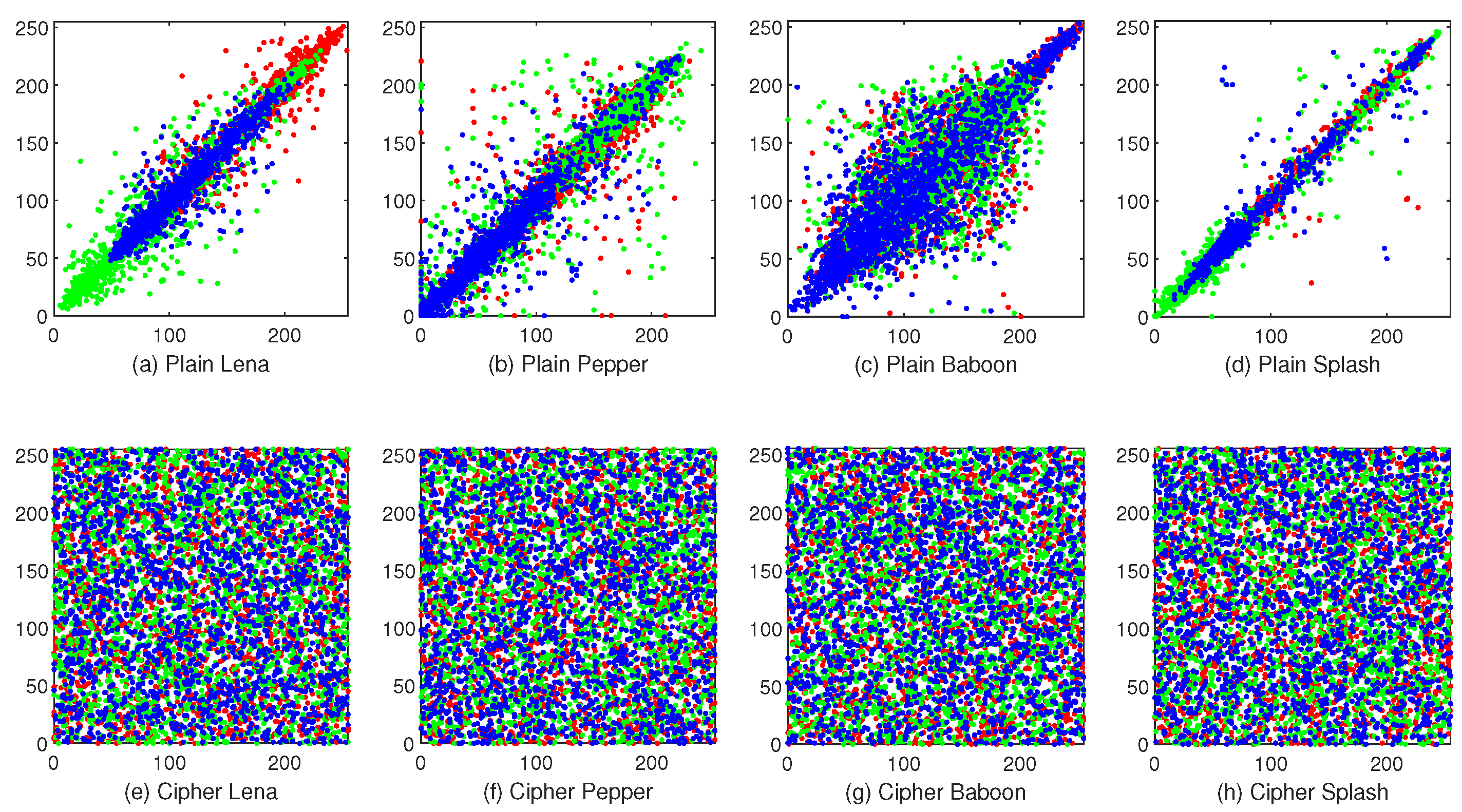
4.4. Correlation

The correlation test refers to adjacent pixels’ relationship. A meaningful image has high correlation because values of adjacent pixels are close to each other. This attribute could be utilized to crack. Therefore, a well-designed encryption scheme should have low enough correlations in three directions: horizontal, vertical, and diagonal directions. Given a pixel sequence that is represented by X = { x 1 , x 2 , , x N } and its adjacent pixel sequence Y = { y 1 , y 2 , , y N } in an image, correlation between X and Y could be denoted as γ X , Y in Equation (20).
γ X , Y = 1 N i = 1 N ( x i D ( X ) ) ( y i D ( Y ) ) D ( X ) D ( Y ) D ( X ) = i = 1 N ( x i E ( X ) ) 2 N E ( X ) = i = 1 N x i N
where E ( X ) is X s mathematical expectation and D ( X ) is standard deviation.
If X and Y are identical, γ X , Y would be a maximum of 1. On the contrary, γ X , Y would be close to 0 when X and Y have few correlations.
Figure 10 depicts the correlation test results. It is obvious that the adjacent pixels’ distributions in plaintext images are concentrated, while the distributions in the cipher images are opposite.
More accurately, Table 6 provides correlation coefficients between plaintext images and cipher images. Additionally Table 7 demonstrates comparisons with references [44,45]. Through this test, it could find that the correlation coefficients of the proposed HCZRNA are extremely close to 0, which means that HCZRNA could effectively break correlations existing in plaintext images. While the comparisons show that the proposed HCZRNA achieves the best results with [44,45] in all cases. This reveals that HCZRNA outperforms when compared schemes in terms of reducing correlations.

4.5. Information Entropy

Information Entropy shows the randomness and uncertainty of image’s pixels. If pixels in an image have uniform distribution, this image could resistant statistical attacks. Because there are 256 gray levels in each channel of color image, the Entropy calculation could be formulated as Equation (21):
H ( C ) = i = 0 255 p ( i ) l o g 2 p ( i )
where C denotes channels of color image and p ( i ) is probability of gray level in whole channel.
The bigger H ( C ) , the bigger uncertainty of image. While the theoretical value of H ( C ) is 8.
Table 8 shows the entropies of all channels of plaintext color images and corresponding cipher images through encryptions by proposed HCZRNA. It is obvious that cipher images have increased entropies a lot from plaintext images and their entropies are very close to the theoretical value. Moreover, a comparison is held between HCZRNA and Refs. [23,29,44,45,46], and the results are stated in Table 9. Among all of the encryption schemes, the proposed HCZRNA achieves the highest entropies in four out of six cases. It could conclude that HCZRNA has the ability to resist statistical attack.

4.6. Differential Attack

The differential attack test is an important security test for image encryption, which reveals the influence on the cipher image caused by a minor change in pixels of plaintext image. If a tiny change on pixels in plaintext image leads to significant different cipher image, that is to say the encryption scheme could resist differential attack.
Two important indices are introduced to measure the ability of differential attack resistance, which is called the number of pixel change rate (NPCR) and the unified average changing intensity (UACI). Additionally, they are defined as Equations (22) and (23):
N P C R = i = 0 h j = 0 w F ( i , j ) × 100 % w × h
U A C I = i = 0 h j = 0 w | e 1 ( i , j ) e 2 ( i , j ) | 255 × w × h
where e 1 and e 2 are two cipher images, and e ( i , j ) means the pixel’s value at coordinate i , j in image e. F ( i , j ) denotes whether the same coordinate’s pixel values in e 1 and e 2 are independent or not, which could be formulated as Equation (24):
F ( i , j ) = 0 , i f e 1 ( i , j ) = e 2 ( i , j ) 1 , i f e 1 ( i , j ) e 2 ( i , j )
For two random images, NPCR and UACI’s expected values are stated as: N P C R = 99.6094 % and U A C I = 33.4635 % for an 8-bit gray image [30].
Hence, to realize the test, one bit would be changed on a random pixel in plaintext image. And both the plaintext image and changed image are encrypted to two different cipher images. Table 10 lists the average results of ten times tests. It could find that all NPCR values and UACI values of cipher images’ different channels exceed the theoretical values. Additionally, comparisons with Refs. [23,29,44,45,46] are shown in Table 11 and Table 12. Through the comparisons, the proposed HCZRNA encryption scheme has better performances on NPCR and UACI, which indicates that HCZRNA could resist differential attack well.
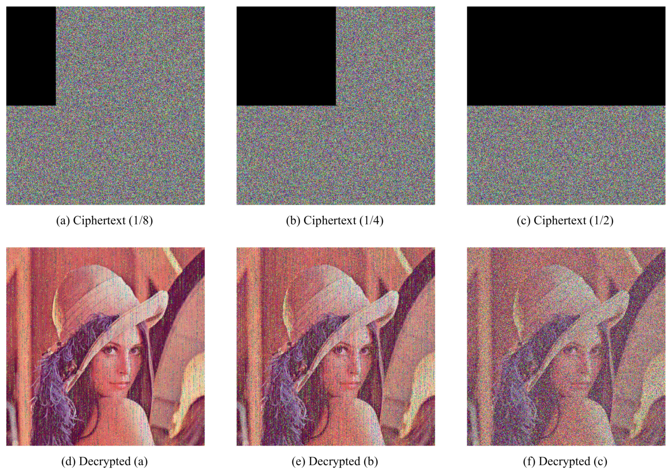
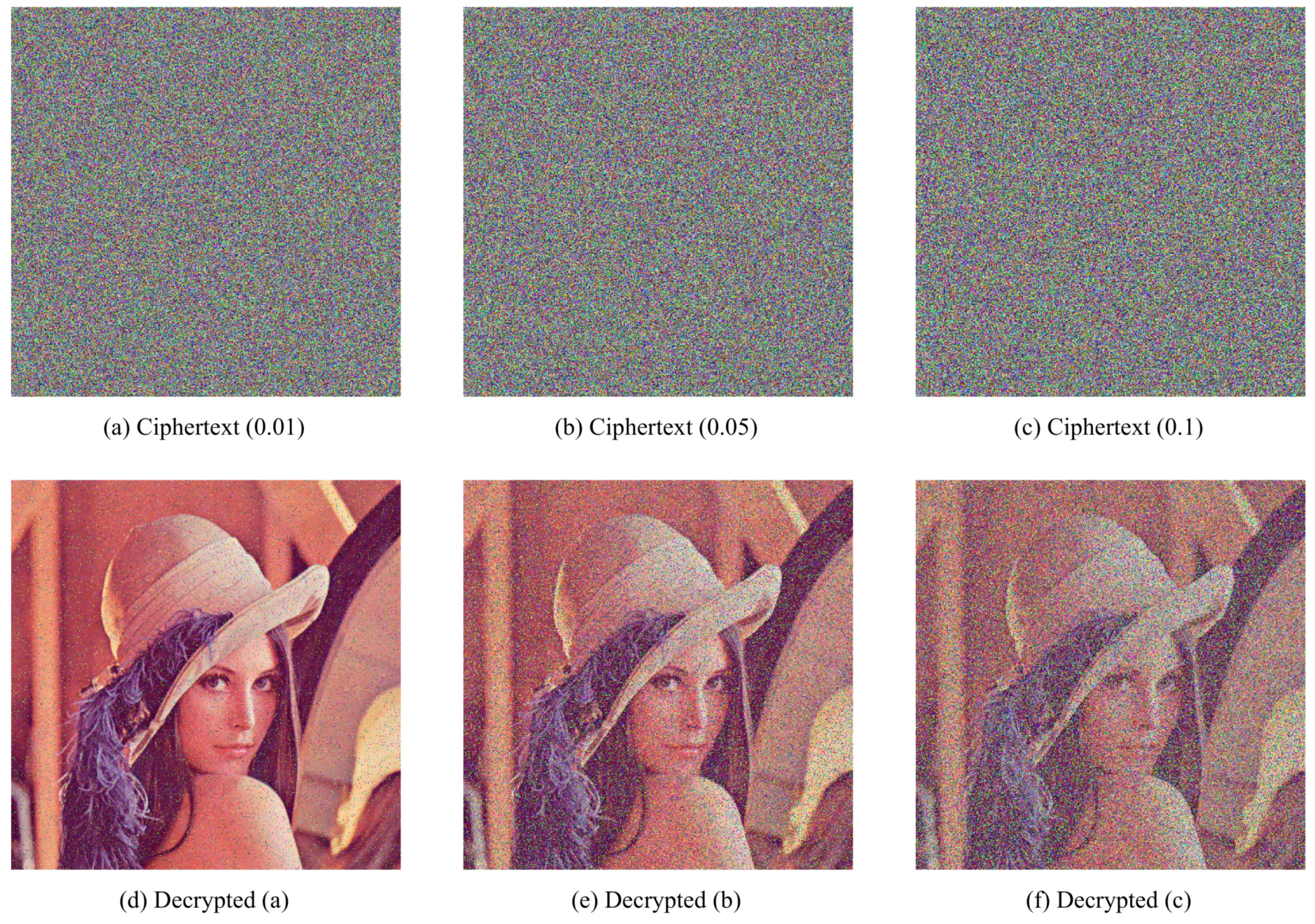
4.7. Robustness

It is unavoidable that there data loss or noise attack occur when cipher images are transmitting. Hence, a well-designed encryption and decryption scheme should resist contamination on cipher images to recover plaintext images without great changes.
To demonstrate robustness of proposed HCZRNA scheme, 12.5 % , 25 % , and 50 % data lose tests and 1 % , 5 % , and 10 % salt and pepper noise tests would presented in Figure 11 and Figure 12.
From the figures, the main information of plaintext images could be identified from decrypted images, which could conclude that HCZRNA has enough robustness for data loss and noise attacks. Here, the Mean Squared Error (MSE) and Peak Signal to Noise Ratio (PSNR) are also utilized to test robustness [48,49], which is formulated as Equation (25).
M S E = 1 h × w i = 1 h j = 1 w [ P ( i , j ) E ( i , j ) ] 2 , P S N R = 20 l o g 10 ( 255 M S E )
where P and E represent two different images. MSE is used to evaluate the difference between two images, and PSNR depicts the ratio between the maximum possible power of a signal and the power of distorting noise that affects the quality of its representation. The lower the MSE, the higher PSNR, which indicates that two images have high similarity. Hence, under noise attacks, if the PSNR between the plaintext image and decrypted image is high, the encryption and decryption schemes are good enough. Table 13 and Table 14 present the results of plaintext image and decrypted image of Lena under data loss and salt and pepper noise attacks.
Through the results, we could find there are high MSEs and low PSNRs in these tables, which figures out that HCZRNA could resist attacks of data loss and noise.

4.8. Running Time

In HCZRNA, the pixels of image would be walked through multiple times in diffusion and RNA operation. Suppose that the size of RGB image is N × N × 3 . For the five parts of encryption processes that are listed in Section 3.1, initial values of hyper-chaotic system are calculated from the security key, which costs O ( 1 ) time complexity; the hyper-chaotic matrices are computed 3 × N × N + 64 times iterations; for permutation, reshape and sort operations are implemented three times; while the diffusion process walks through each pixel two times, which costs O ( 2 × N × N × 3 ) ; at last, as RNA operation walks through all 6-bit codons that are transformed from 8-bit pixels, the times of iteration are increased to 4 3 × N × N × 3 . Hence, the time complexity of HCZRNA could be calculated as O ( 1 + 3 × N × N + 64 + 3 + 2 × N × N × 3 + 4 3 × N × N × 3 ) = O ( 13 N 2 + 68 ) = O ( N 2 ) . Using the experiment environment that is listed in this section, the running times of encryption and decryption could be stated in Table 15. Although the time costs of encryption and decryption are not very good, the time complexity is also a polynomial time, which could be tolerable. Additionally, the processes of RNA operation on different codons have no correlation with each other, which could improve computational time by computing RNA operation in parallel.

5. Conclusions

A novel hyper-chaotic system based image encryption scheme is proposed with 3D transformed Zigzag and RNA operation in this paper. By using the 6D hyper-chaotic system, three auxiliary matrices are generated, including one permutation index matrix, one mask matrix for Zigzag, and one codon table index matrix. Subsequently, two rounds 3D transformed Zigzag diffusion mechanism is proposed for pixels diffusion with each other. Nevertheless, additional encryption with RNA codons makes more reliable and secure results through employing codons tables and security keys. Through simulations, the proposed HCZRNA has better performances on the resistance of different types attacks than the compared encryption schemes, while the speed is not ideal, since it is a complex process. On the premise of ensuring performance, we would simplify diffusion and RNA operation processes and optimize the encryption steps for improving speed in the future.

Author Contributions

Conceptualization, D.Z. and T.L.; Data curation, L.C.; Formal analysis, D.Z.; Funding acquisition, T.L.; Investigation, T.L.; Methodology, D.Z. and T.L.; Project administration, T.L.; Resources, D.Z.; Software, D.Z.; Supervision, D.Z. and T.L.; Validation, L.C. and T.L.; Visualization, L.C.; Writing—original draft, D.Z.; Writing—review & editing, T.L. All authors have read and agreed to the published version of the manuscript.

Funding

This work was supported by the Ministry of Education of Humanities and Social Science Project (Grant No. 19YJAZH047) and the Scientific Research Fund of Sichuan Provincial Education Department (Grant No. 17ZB0433).

Institutional Review Board Statement

Not applicable.

Informed Consent Statement

Not applicable.

Data Availability Statement

Data available on request.

Acknowledgments

We gratefully acknowledge the reviewers for their comments and suggestions.

Conflicts of Interest

The authors declare no conflict of interest.

Abbreviations

The following abbreviations are used in this manuscript:
6D6 Dimensional
RNARibonucleic acid
HCZRNAHyper-chaotic color image encryption mechanism based
on transformed Zigzag diffusion and RNA operations
RGBRed Greeen Blue

References

  1. Sneha, P.S.; Sankar, S.; Kumar, A.S. A chaotic colour image encryption scheme combining Walsh–Hadamard transform and Arnold–Tent maps. J. Ambient. Intell. Humaniz. Comput. 2020, 11, 1289–1308. [Google Scholar] [CrossRef]
  2. Wang, H.; Xiao, D.; Chen, X.; Huang, H. Cryptanalysis and enhancements of image encryption using combination of the 1D chaotic map. Signal Process. 2018, 144, 444–452. [Google Scholar] [CrossRef]
  3. Jeng, F.G.; Huang, W.L.; Chen, T.H. Cryptanalysis and improvement of two hyper-chaos-based image encryption schemes. Signal Process. Image Commun. 2015, 34, 45–51. [Google Scholar] [CrossRef]
  4. Jithin, K.C.; Sankar, S. Colour image encryption algorithm combining Arnold map, DNA sequence operation, and a Mandelbrot set. J. Inf. Secur. Appl. 2020, 50, 102428. [Google Scholar] [CrossRef]
  5. Zhang, Y. Test and verification of AES used for image encryption. 3D Res. 2018, 9, 1–27. [Google Scholar] [CrossRef]
  6. Xian, Z.H.; Sun, S.L. Image Encryption Algorithm Based on Chaos and S-Boxes Scrambling. Adv. Mater. Res. 2010, 171–172, 299–304. [Google Scholar] [CrossRef]
  7. Zhou, Y.; Hua, Z.; Pun, C.M.; Chen, C.L.P. Cascade Chaotic System With Applications. IEEE Trans. Cybern. 2015, 45, 2001–2012. [Google Scholar] [CrossRef] [PubMed]
  8. Liu, L.; Wang, Y.N.; Hou, L.; Feng, X.R. Easy encoding and low bit–error–rate chaos communication system based on reverse–time chaotic oscillator. IET Signal Process. 2017, 11, 869–876. [Google Scholar] [CrossRef]
  9. Zhang, L.; Liao, X.; Wang, X. An image encryption approach based on chaotic maps. Chaos Solitons Fractals 2005, 24, 759–765. [Google Scholar] [CrossRef]
  10. Bouslehi, H.; Seddik, H. Innovative image encryption scheme based on a new rapid hyperchaotic system and random iterative permutation. Multimed. Tools Appl. 2018, 77, 30841–30863. [Google Scholar] [CrossRef]
  11. Zhang, Y.; Wen, W.; Su, M.; Li, M. Cryptanalyzing a novel image fusion encryption algorithm based on DNA sequence operation and hyper-chaotic system. Optik 2014, 125, 1562–1564. [Google Scholar] [CrossRef]
  12. Mohammad Seyedzadeh, S.; Mirzakuchaki, S. A fast color image encryption algorithm based on coupled two-dimensional piecewise chaotic map. Signal Process. 2012, 92, 1202–1215. [Google Scholar] [CrossRef]
  13. Li, T.; Shi, J.; Zhang, D. Color image encryption based on joint permutation and diffusion. J. Electron. Imaging 2021, 30, 013008. [Google Scholar] [CrossRef]
  14. Askar, S.S.; Karawia, A.A.; Alshamrani, A. Image Encryption Algorithm Based on Chaotic Economic Model. Math. Probl. Eng. 2015, 2015, 1–10. [Google Scholar] [CrossRef]
  15. Shaikh, N.; Chapaneri, S.; Jayaswal, D. Hyper chaotic color image cryptosystem. In Proceedings of the 2016 IEEE International Conference on Advances in Computer Applications (ICACA), Coimbatore, India, 24 October 2016; pp. 239–243. [Google Scholar] [CrossRef]
  16. Li, C.; Zhao, F.; Liu, C.; Lei, L.; Zhang, J. A Hyperchaotic Color Image Encryption Algorithm and Security Analysis. Secur. Commun. Netw. 2019, 2019, 1–8. [Google Scholar] [CrossRef]
  17. Zhou, Y.; Bao, L.; Chen, C.P. A new 1D chaotic system for image encryption. Signal Process. 2014, 97, 172–182. [Google Scholar] [CrossRef]
  18. Kadir, A.; Aili, M.; Sattar, M. Color image encryption scheme using coupled hyper chaotic system with multiple impulse injections. Opt. Int. J. Light Electron Opt. 2017, 129, 231–238. [Google Scholar] [CrossRef]
  19. Li, C.; Zhang, L.Y.; Ou, R.; Wong, K.W.; Shu, S. Breaking a novel colour image encryption algorithm based on chaos. Nonlinear Dyn. 2012, 70, 2383–2388. [Google Scholar] [CrossRef] [Green Version]
  20. Xingyuan, W.; Junjian, Z.; Guanghui, C. An image encryption algorithm based on ZigZag transform and LL compound chaotic system. Opt. Laser Technol. 2019, 119, 105581. [Google Scholar] [CrossRef]
  21. Xu, X.; Feng, J. Research and Implementation of Image Encryption Algorithm Based on Zigzag Transformation and Inner Product Polarization Vector. In Proceedings of the 2010 IEEE International Conference on Granular Computing, San Jose, CA, USA, 14–16 August 2010; pp. 556–561. [Google Scholar] [CrossRef]
  22. Li, Y.; Li, X.; Jin, X.; Zhao, G.; Ge, S.; Tian, Y.; Zhang, X.; Zhang, K.; Wang, Z. An Image Encryption Algorithm Based on Zigzag Transformation and 3-Dimension Chaotic Logistic Map. In Applications and Techniques in Information Security; Niu, W., Li, G., Liu, J., Tan, J., Guo, L., Han, Z., Batten, L., Eds.; Springer: Berlin/Heidelberg, Germany, 2015; Volume 557, pp. 3–13. [Google Scholar] [CrossRef]
  23. Wang, X.; Guan, N. A novel chaotic image encryption algorithm based on extended Zigzag confusion and RNA operation. Opt. Laser Technol. 2020, 131, 106366. [Google Scholar] [CrossRef]
  24. Feixiang, Z.; Mingzhe, L.; Kun, W.; Hong, Z. Color image encryption via Hénon-zigzag map and chaotic restricted Boltzmann machine over Blockchain. Opt. Laser Technol. 2021, 135, 106610. [Google Scholar] [CrossRef]
  25. Sahasrabuddhe, A.; Laiphrakpam, D.S. Multiple images encryption based on 3D scrambling and hyper-chaotic system. Inf. Sci. 2021, 550, 252–267. [Google Scholar] [CrossRef]
  26. Hu, T.; Liu, Y.; Gong, L.H.; Ouyang, C.J. An image encryption scheme combining chaos with cycle operation for DNA sequences. Nonlinear Dyn. 2017, 87, 51–66. [Google Scholar] [CrossRef]
  27. Li, T.; Yang, M.; Wu, J.; Jing, X. A novel image encryption algorithm based on a fractional-order hyperchaotic system and DNA computing. Complexity 2017, 2017, 9010251. [Google Scholar] [CrossRef] [Green Version]
  28. Liu, Y.; Wang, J.; Fan, J.; Gong, L. Image encryption algorithm based on chaotic system and dynamic S-boxes composed of DNA sequences. Multimed. Tools Appl. 2016, 75, 4363–4382. [Google Scholar] [CrossRef]
  29. Chai, X.; Fu, X.; Gan, Z.; Lu, Y.; Chen, Y. A color image cryptosystem based on dynamic DNA encryption and chaos. Signal Process. 2019, 155, 44–62. [Google Scholar] [CrossRef]
  30. Hu, T.; Liu, Y.; Gong, L.H.; Guo, S.F.; Yuan, H.M. Chaotic image cryptosystem using DNA deletion and DNA insertion. Signal Process. 2017, 134, 234–243. [Google Scholar] [CrossRef]
  31. Wu, J.; Shi, J.; Li, T. A novel image encryption approach based on a hyperchaotic system, pixel-level filtering with variable kernels, and DNA-level diffusion. Entropy 2020, 22, 5. [Google Scholar] [CrossRef] [PubMed] [Green Version]
  32. Liu, P.; Zhang, T.; Li, X. A new color image encryption algorithm based on DNA and spatial chaotic map. Multimed. Tools Appl. 2019, 78, 14823–14835. [Google Scholar] [CrossRef]
  33. Mahmud, M.; ur Rahman, A.; Lee, M.; Choi, J.Y. Evolutionary-based image encryption using RNA codons truth table. Opt. Laser Technol. 2020, 121, 105818. [Google Scholar] [CrossRef]
  34. Abbasi, A.A.; Mazinani, M.; Hosseini, R. Chaotic evolutionary-based image encryption using RNA codons and amino acid truth table. Opt. Laser Technol. 2020, 132, 106465. [Google Scholar] [CrossRef]
  35. Yadollahi, M.; Enayatifar, R.; Nematzadeh, H.; Lee, M.; Choi, J.Y. A novel image security technique based on nucleic acid concepts. J. Inf. Secur. Appl. 2020, 53, 102505. [Google Scholar] [CrossRef]
  36. Li, T.; Shi, J.; Li, X.; Wu, J.; Pan, F. Image encryption based on pixel-level diffusion with dynamic filtering and DNA-level permutation with 3D Latin cubes. Entropy 2019, 21, 319. [Google Scholar] [CrossRef] [PubMed] [Green Version]
  37. Mezatio, B.A.; Motchongom Tingue, M.; Kengne, R.; Tchagna Kouanou, A.; Fozin Fonzin, T.; Tchitnga, R. Complex dynamics from a novel memristive 6D hyperchaotic autonomous system. Int. J. Dyn. Control. 2020, 8, 70–90. [Google Scholar] [CrossRef]
  38. Li, T.; Zhou, M. ECG Classification Using Wavelet Packet Entropy and Random Forests. Entropy 2016, 18, 285. [Google Scholar] [CrossRef]
  39. Li, T.; Qian, Z.; He, T. Short-term load forecasting with improved CEEMDAN and GWO-based multiple kernel ELM. Complexity 2020, 2020, 1209547. [Google Scholar] [CrossRef]
  40. Deng, W.; Shang, S.; Cai, X.; Zhao, H.; Song, Y.; Xu, J. An improved differential evolution algorithm and its application in optimization problem. Soft Comput. 2021, 1–22. [Google Scholar] [CrossRef]
  41. Song, Y.; Wu, D.; Deng, W.; Gao, X.; Li, T.; Zhang, B.; Li, Y. MPPCEDE: Multi-population parallel co-evolutionary differential evolution for parameter optimization. Energy Conv. Manag. 2021, 228, 113661. [Google Scholar] [CrossRef]
  42. Li, T.; Zhou, M.; Guo, C.; Luo, M.; Wu, J.; Pan, F.; Tao, Q.; He, T. Forecasting crude oil price using EEMD and RVM with adaptive PSO-based kernels. Energies 2016, 9, 1014. [Google Scholar] [CrossRef] [Green Version]
  43. Deng, W.; Xu, J.; Cai, X.; Song, Y.; Zhao, H. Differential evolution algorithm with wavelet basis function and optimal mutation strategy for complex optimization problem. Appl. Soft. Comput. 2021, 100, 106724. [Google Scholar] [CrossRef]
  44. Liu, L.; Zhang, L.; Jiang, D.; Guan, Y.; Zhang, Z. A Simultaneous Scrambling and Diffusion Color Image Encryption Algorithm Based on Hopfield Chaotic Neural Network. IEEE Access 2019, 7, 185796–185810. [Google Scholar] [CrossRef]
  45. Pak, C.; Huang, L. A new color image encryption using combination of the 1D chaotic map. Signal Process. 2017, 138, 129–137. [Google Scholar] [CrossRef]
  46. Mohamed, H.G.; ElKamchouchi, D.H.; Moussa, K.H. A Novel Color Image Encryption Algorithm Based on Hyperchaotic Maps and Mitochondrial DNA Sequences. Entropy 2020, 22, 158. [Google Scholar] [CrossRef] [Green Version]
  47. Alvarez, G.; Li, S. Some basic cryptographic requirements for chaos-based cryptosystems. Int. J. Bifurc. Chaos 2006, 16, 2129–2151. [Google Scholar] [CrossRef] [Green Version]
  48. Özkaynak, F. Brief review on application of nonlinear dynamics in image encryption. Nonlinear Dyn. 2018, 92, 305–313. [Google Scholar] [CrossRef]
  49. Murillo-Escobar, M.A.; Meranza-Castillón, M.O.; López-Gutiérrez, R.M.; Cruz-Hernández, C. Suggested Integral Analysis for Chaos-Based Image Cryptosystems. Entropy 2019, 21, 815. [Google Scholar] [CrossRef] [PubMed] [Green Version]
Figure 1. The attractors of six-dimensional (6D) hyper-chaotic system.
Entropy 23 00361 g001
Figure 2. 4 × 4 traditional Zigzag scramble.
Entropy 23 00361 g002
Figure 3. Color image to cube.The first row is three channels of a color image. The second row is the triangles generated from image. Additionally, the third row is the placement of triangles on a cube.
Entropy 23 00361 g003
Figure 4. Three-dimensional (3D) transformed Zigzag diffusion. (a) is the Zigzag diffusion process on the front side of cube. (b) is the Zigzag diffusion process on the back side of cube.
Entropy 23 00361 g004
Figure 5. 3D transformed Zigzag path. For all triangles on the cube, 3D transformed Zigzag diffusion is implemented through this order.
Entropy 23 00361 g005
Figure 6. The process of encryption.
Entropy 23 00361 g006
Figure 7. Reverse traversal.
Entropy 23 00361 g007
Figure 8. The order of Zigzag in decryption.
Entropy 23 00361 g008
Figure 9. Histogram. image (a,c,e) are the histograms of three channels of Baboon, and image (b,d,f) are the histograms of corresponding channels of encrypted Baboon.
Entropy 23 00361 g009
Figure 10. Correlations.The first row is correlations of plaintext images, and the second row is correlations of cipher images.
Entropy 23 00361 g010
Figure 11. Cropping attack tests. The first row is cipher images with 12.5 % , 25 % and 50 % data loss, and the second row is decrypted images from the first row.
Entropy 23 00361 g011
Figure 12. Noise attack tests. The first row is cipher images with 1 % , 5 % , 10 % salt and pepper noise, and the second row is decrypted images from the first row.
Entropy 23 00361 g012
Table 1. Binary representation of RNA.
RNA BasesACGU
Binary00011011
Table 2. RNA codon table.
#Bin.Codon#Bin.Codon#Bin.Codon#Bin.Codon
0000000AAA16010000CAA32100000GAA48110000UAA
1000001AAC17010001CAC33100001GAC49110001UAC
2000010AAG18010010CAG34100010GAG50110010UAG
3000011AAU19010011CAU35100011GAU51110011UAU
4000100ACA20010100CCA36100100GCA52110100UCA
5000101ACC21010101CCC37100101GCC53110101UCC
6000110ACG22010110CCG38100110GCG54110110UCG
7000111ACU23010111CCU39100111GCU55110111UCU
8001000AGA24011000CGA40101000GGA56111000UGA
9001001AGC25011001CGC41101001GGC57111001UGC
10001010AGG26011010CGG42101010GGG58111010UGG
11001011AGU27011011CGU43101011GGU59111011UGU
12001100AUA28011100CUA44101100GUA60111100UUA
13001101AUC29011101CUC45101101GUC61111101UUC
14001110AUG30011110CUG46101110GUG62111110UUG
15001111AUU31011111CUU47101111GUU63111111UUU
Table 3. Testing images.
ImageSize ( h × w × c )ImageSize ( h × w × c )
Lena 256 × 256 × 3 Baboon 512 × 512 × 3
Peppers 256 × 256 × 3 Splash 512 × 512 × 3
Table 4. Differences between the cipher images.
ImageLenaPepperBaboonSplash
Difference 99.59 % 99.62 % 99.61 % 99.60 %
Table 5. Histogram statistics.
ImageChannelsPlaintextCiphertext
α β α β
LenaR65,30625524815
G30,66517525816
B91,93930323215
PepperR57,41323924915
G119,41134523815
B151,64438923715
BaboonR165,67940752022
G285,61653453223
B159,88539954123
SplashR1,211,325110056623
G1,541,948124149522
B2,958,482172050422
Table 6. The correlation coefficients of the testing images.
ImageChannelsPlaintextCiphertext
HorizontalVerticalDiagonalHorizontalVerticalDiagonal
LenaR0.95120.97550.94440.00460.00240.0051
G0.95120.96790.9276−0.0027−0.00070.0002
B0.95120.94790.9021−0.00230.00140.0004
BaboonR0.92180.86240.85310.00030.00010.0015
G0.92180.75910.7299−0.00100.00040.0020
B0.92180.87820.84110.0005−0.00220.0012
Table 7. Comparisons of correlation coefficients.
ImageChannels PlaintextCiphertext
HCZRNARef. [44]Ref. [45]
BaboonRHorizontal0.92180.00030.0054−0.0073
Vertical0.86240.0001−0.0042−0.0059
Diagonal0.85310.0015−0.0177−0.0136
GHorizontal0.9218−0.0010−0.00550.0046
Vertical0.75910.00040.0119−0.0077
Diagonal0.72990.00200.0046−0.0044
BHorizontal0.92180.0005−0.0021−0.0067
Vertical0.8782−0.00220.0104−0.0111
Diagonal0.84110.0012−0.00210.0122
Table 8. Information Entropies of testing images.
ImageChannelsLenaPeppersBaboonSplash
PlaintextR7.23537.33697.70676.9481
G7.56837.43947.47446.8845
B6.91767.02197.75226.1265
CiphertextR7.99737.99727.99937.9993
G7.99707.99707.99937.9994
B7.99727.99727.99937.9993
Table 9. Comparison of entropies.
ImageChannelPlaintextHCZRNARef. [29]Ref. [23]Ref. [44]Ref. [45]Ref. [46]
LenaR7.23537.99737.99717.9973--7.9973
G7.56837.99707.99717.9972--7.9975
B6.91767.99727.99717.9971--7.9975
BaboonR7.70677.99937.9926-7.99937.99937.9970
G7.47447.99937.9926-7.99937.99937.9978
B7.75227.99937.9926-7.99937.99927.9987
Table 10. The mean number of pixel change rate (NPCR) and unified average changing intensity (UACI) of cipher images.
ImageNPCR(%)UACI(%)
RGBRGB
Lena99.661999.627299.646033.617733.604833.6422
Peppers99.648199.640499.623933.720833.570133.6435
Baboon99.615999.676999.611533.519633.520333.5049
Splash99.621999.693499.625333.498333.511433.4816
Table 11. Average NPCR (%) of running the schemes 10 times.
ImageChannelHCZRNARef. [29]Ref. [23]Ref. [44]Ref. [45]Ref. [46]
LenaR99.661999.6099.6323--99.615
G99.627299.6199.6109--99.62
B99.646099.6199.6338--99.617
BaboonR99.615999.6083-99.603799.603799.6140
G99.676999.6065-99.604899.601799.6073
B99.611599.6094-99.605999.604399.6292
Table 12. Average UACI (%) of running the schemes 10 times.
ImageChannelHCZRNARef. [29]Ref. [23]Ref. [44]Ref. [45]Ref. [46]
LenaR33.617733.5633.4683--33.4732
G33.604833.4533.4341--33.3428
B33.642233.4933.4991--33.4647
BaboonR33.519633.4939-33.442729.963033.4843
G33.520333.4295-33.460528.570833.4690
B33.504933.4856-31.974731.257433.4965
Table 13. Mean Squared Error (MSE) and Peak Signal to Noise Ratio (PSNR) under data loss.
Data LossMSEPSNR
12.5 % 119517.35
25 % 231514.48
50 % 450211.60
Table 14. MSE and PSNR under salt and pepper noise.
Salt and Pepper NoiseMSEPSNR
1 % 61020.28
5 % 268413.84
10 % 449011.61
Table 15. Running time (unit: second).
Image SizeEncryptionDecryption
64 × 64 × 3 0.590.44
128 × 128 × 3 2.391.77
256 × 256 × 3 9.366.96
512 × 512 × 3 37.5428.49
Publisher’s Note: MDPI stays neutral with regard to jurisdictional claims in published maps and institutional affiliations.

