1. Introduction
Refrigeration plays a major role in many different sectors, ranging from food, air conditioning, healthcare, industry and, especially energy. Nowadays, the number of refrigeration air-conditioning and heat pump systems in operation worldwide is roughly 5 billion, if we consider 2.6 billion air-conditioning stationary and mobile units and 2 billion domestic refrigerators and freezers [
1]. The global electricity demand for refrigeration, including air conditioning, could more than double by 2050 [
2]. The Kyoto Protocol was adopted in 1997 and entered into force on 16 February 2005. It aimed to prevent global warming due to the use of HCFC/CFC refrigerants and the objective is to stabilise greenhouse gas concentrations at a level that would prevent dangerous anthropogenic (human-induced) interference with the climate system. It can be seen that developing a cooling system without using HCFC/CFC working fluid is unavoidable in the future. Stirling coolers are used as commercial cryocoolers in the cryogenic field, military applications, liquid air production plants, cooling electronics, carbon capture and domestic applications [
3,
4,
5,
6].
Thus, in order to decrease electricity consumption and to prevent global warning, it is necessary to optimize these cooling machines and systems, particularly the heat exchangers. These are systems to transfer heat between two or more fluids at different temperatures and pressures, separated by a heat-transfer surface. The optimal conversion of heat energy involves a heat exchanger in order to minimize the energy consumption and costs regarding several criteria, such as materials, geometries, flow rates, flow arrangements, operating temperatures and pressures, and transient or steady-state operation [
7,
8,
9,
10]. In the field of refrigeration, the objective is to extract heat from different products in gas, liquid or solid state with minimum energy cost and maximum efficiency.
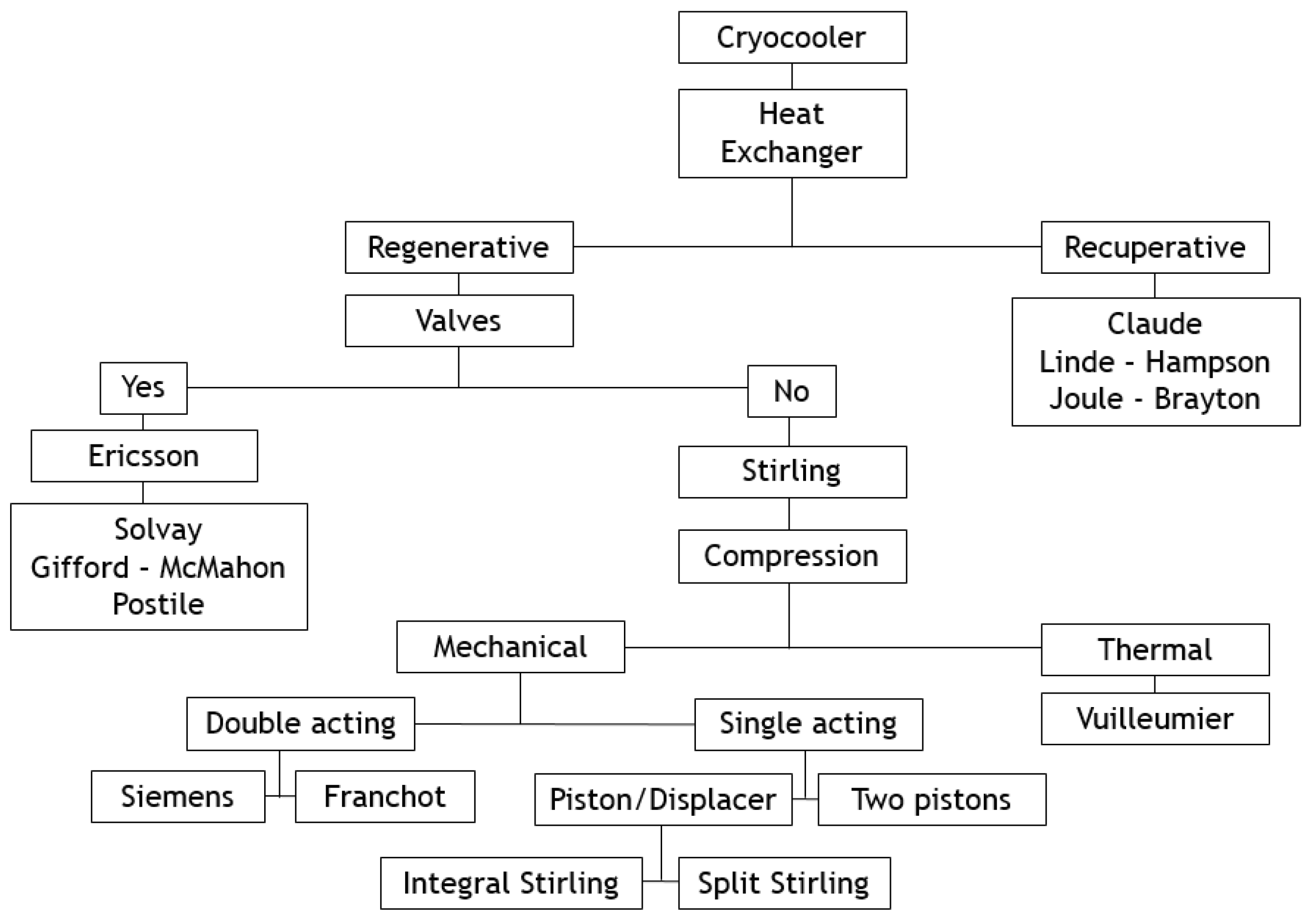
This paper deals with the optimization of a heat exchanger (the freezer) of a refrigerating machine, used in a Stirling machine working at low and moderate temperatures (between −100 and 0 °C). This machine is a member of the cryocooler’s technology family (
Figure 1). Generally, the closed cycle of the Stirling machine concerns engines, coolers and heat pumps [
11,
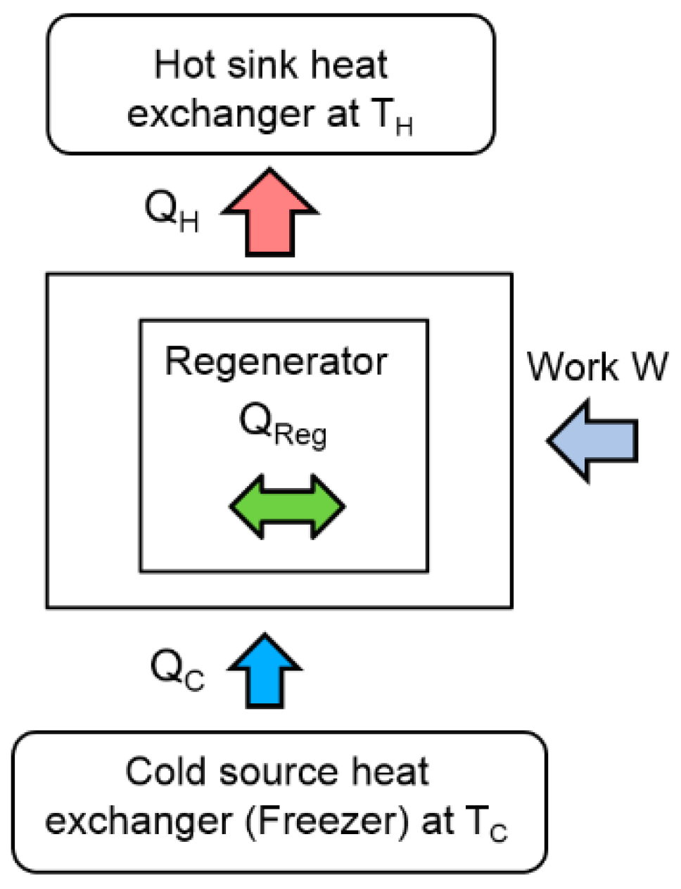
12]. The thermodynamic cycle is the same in each case except that the process direction is reversed. In its theoretical refrigerating cycle (
Figure 2,
Figure 3 and
Figure 4), the working fluid is compressed at the highest constant temperature
TH (1–2) and Q
H is the corresponding heat rejected to the environment through the cooler exchanger.
The fluid is cooled at constant volume (2–3) by the heat Q
R rejected from the gas to the regenerator. Then, the expansion work (3–4) takes place at the lowest constant temperature T
C and the external heat Q
C is extracted from the surroundings and supplied to the gas through the freezer exchanger. Finally, the fluid is heated from the temperature T
C to T
H by the corresponding heat Q
R stored in the regenerator during the process at constant volume (4–1). Both isochoric processes take place in a porous heat exchanger called the regenerator [
4,
5], whose efficiency is a key point of Stirling machine performances.
In refrigeration operation, heat is then rejected to the hot sink during the compression (1–2) and provided to the cold source in the compression stage (3–4). In a Stirling machine, these exchangers play a crucial role in the optimization of the performances. The objective of this paper is to optimize the performance of these exchangers by means of the second law of analysis and to study the behavior of the entropy generation. This approach focuses on the cold source exchanger (the freezer) at constant temperature
TC (
Figure 5), considering that the same approach could concern the exchanger of the hot sink at temperature
TH.
Entropy generation analysis is considered as a measure of sustainability because a process with a lower entropy generation rate is more sustainable and able to realize energy conversion more efficiently. Nowadays, new indicators based on an engineering approach of irreversibility are used to evaluate both the technological level and the environmental impact of the production process and the socio-economic conditions [
13,
14,
15]. Heat and mass transfer processes and thermal systems like heat exchangers have been studied and optimized in order to minimize the irreversibilities using the second law of thermodynamics in fundamental works published since the 1980s [
16,
17,
18,
19]. The second law of thermodynamics method is applied to general convective heat transfer flows in ducts and it defines the entropy rate contributed by heat transfer irreversibilities and fluid flow frictions. Convective heat transfer through ducts is analyzed with constant heat flux or constant temperature [
20,
21,
22,
23,
24].
The main objective of this work is to determine the optimum duct or heat exchanger geometry which minimize losses for a range of Reynold numbers, hydraulic diameters, and fins geometry (thickness, spacing). We describe the experimental setup based on a Beta Stirling refrigerator, specifically focusing on the cold heat exchanger. Then, we will focus our study on the second law analysis of the experimental performances of the cold heat exchanger. The model and optimization present complementary criteria and alternative ratios, like the dimensionless entropy ratio, irreversibility distribution ratio and Bejan number, that we used in this study to determine the performances of a cold heat exchanger of a Stirling refrigerator.
3. Mathematical Model
In a heat exchanger, real processes present irreversibilities caused by losses due to fluid friction, heat exchange across a finite temperature difference and heat exchange with the environment [
26]. Second law analysis is a method developed to design systems on minimum entropy production caused by these losses [
16,
27,
28]. The second law equation describes the irreversibility of the process, in terms of entropy generation rate
within the heat exchanger between inlet and outlet ducts of a system boundary.
For steady operation (
), consider an arbitrary flow passage of length
dx with a finite temperature difference ∆
T = (
Tw −
T) between the wall temperature
Tw and the bulk temperature
T of the fluid, the rate of entropy generation per unit length is
where
τ =
ΔT/
T a dimensionless temperature difference,
the wall heat transfer per unit length,
the mass flow rate and
the longitudinal pressure gradient.
The quantity
corresponds to the entropy generation rate accounting for the heat transfer irreversibility (
) and the term
corresponds to the entropy generation rate for the fluid friction irreversibility (
). Based on these quantities, Bejan defined the irreversibility distribution ratio
ϕ by [
29]:
The entropy generation irreversibility can be described by the Bejan number
Be as the ratio between the heat transfer irreversibility and the total irreversibility due to heat transfer and fluid flow [
30,
31]:
The heat transfer dominates when (or ) and the fluid friction dominates when Be → 0 (or ϕ → ∞). The ideal equilibrium between these two irreversibilities is reached for Be = 1/2 or (ϕ = 1).
Assuming the refrigerating fluid to be incompressible, Equation (2) can be written as:
Equation (6) represents the entropy generation per unit length due to heat transfer across finite temperature difference and to fluid friction, respectively. If we consider that the dimensionless temperature difference
τ =
ΔT/
T ≪ 1, the following equation is obtained:
Derived from
Figure 5, the
Figure 6 presents the control volume of the Stirling cold heat exchanger for energy and entropy analysis.
The cold heat exchanger is a double-pipe type heat exchanger made up of two concentric circular tubes (Label 1 in
Figure 6). The incompressible coolant liquid flows continuously, with a mass flow
, through the annular passage under the temperature
and pressure
gradients, respectively. The other fluid is the working gas (Nitrogen) of the Stirling refrigerator and it flows alternatively (corresponding to the rotational frequency of the machine) at constant temperature
TC in the inner tube corresponding to the cylinder of the machine (Labels 8 and 10). The heat flux
is extracted from the surface and maintained at the constant temperature
TC along the heat exchanger surface. This temperature is measured in the expansion volume of the refrigerator and depends on different parameters like thermal load, pressure of the gas, rotational speed [
12,
32]. The heat exchanger is considered as a duct at constant temperature
TC with a hydraulic diameter
Dh and a total length
L corresponding to mean distance between the inlet and the outlet of the heat exchanger.
Equation (7) is integrated along the length, and the expression of the entropy generation
becomes [
21,
22,
33]:
where
and
.
The hydraulic diameter approach is a simple dimensional parameter method to calculate the heat transfer and the pressure drop in the heat exchanger. The hydraulic diameter
Dh of the cold heat exchanger is defined [
34].
The rate of entropy generation is represented as the dimensionless form
NS [
29]:
where
is the heat capacity rate within the heat exchanger. In this work, the heat capacity rate is the product of the mass flow and specific heat capacity rate of the incompressible fluid.
The fluid flow is considered to be fully developed inside the exchanger. The friction factor
f is given for a well-known correlation [
35,
36,
37]. The complex flow field generated by the internal geometry of the heat exchanger influences the pressure gradient required to drive the flow. The friction factor
f is defined
with the Reynolds number
. The two constants
a and
b depend on the fluid properties, the flow regime and the geometry constraints of the heat exchanger. These two coefficients were identified from data reduction experimental results [
38] and pressure drop data were correlated to ±10% for
Re < 2000 (laminar flow condition).
The average of the inlet and outlet bulk temperatures is used to calculate the physical parameters (density, viscosity and specific heat capacity) of the coolant liquid (55/45 by mass ethylene glycol/water mixture) in the temperature range 240 K <
T < 300 K (
Table 2 and
Figure 7). Ethylene glycol lowers the specific heat capacity of water mixtures relative to pure water.
Considering Equation (10), we get:
The first term corresponds to dimensionless rate of entropy production due to the thermal irreversibilities (NS,∆T), and the second one, (NS,∆P), to the pressure irreversibilities.
From Equation (13), we introduce a Bejan number
based on a dimensionless entropy ratio:
4. Results and Discussion
Both fluid friction and heat transfer contribute to the rate of entropy generation represented by Equations (4), (5), (10) and (13). Entropy generation is investigated with the effects of different parameters concerning the cold heat exchanger (Length
L, hydraulic diameter
Dh, mass flow
, temperature
TC of the gas inside the cold volume of the Stirling refrigerator). Before examining the dependence of these parameters on entropy generation, it is necessary to discuss the following observations and assumptions. Measurements are performed in the cold heat exchanger (the freezer) of the Stirling refrigerator and concern the temperatures and pressures of the working gas inside the expansion volume corresponding to the internal cold heat exchanger, mass flow and pressures of the coolant liquid (mix water/ethylene–glycol) and rotational speed of the refrigerator (
Figure 6).
In this section, we used constant values of inlet and outlet temperatures fixed at
Ti = 300 K and
To = 260 K, respectively. The temperature
To corresponds to a constraint we need for an industrial process not described in this article. The hydraulic diameter of the cold heat exchanger is
Dh = 0.015 m and its characteristic length is
L = 0.10 m. For the coolant liquid, the variation of viscosity with temperature is responsible for most of the property effects. The coolant fluid flow
vary in the range (0.003–0.010 kg.s
−1). In our study, we performed experiments with two mass flows rates of coolant liquid
= 0.003 kg.s
−1 and
= 0.004 kg.s
−1, respectively. At low temperatures, the viscosity increases significantly and between 243 K and 263 K the dynamic viscosity increases in a ratio of around 7 (
Table 2) and has the direct effect of increasing the fluid frictions. We used the film temperature based on the wall and mean bulk temperatures of the liquid flow rate to calculate its properties. We performed the measurements when the machine was operating in steady state at a fixed rotational speed
ω with 35 rad.s
−1 <
ω < 80 rad.s
−1 and for a given working gas temperature
TC with 190 K <
TC < 273 K. At each extremity of the exchanger (inlet and outlet on
Figure 6), we collected the characteristic data of the coolant fluid: the refrigerant mass flow rate
, the inlet and outlet pressures
Pi and
Po and their corresponding temperatures
Ti and
To, respectively. Then, we introduced the experimental data in the thermodynamic model concerning the temperatures, the pressures, the mass flows, the hydraulic diameter, and the mean length
L of the cold heat exchanger. We finally used the model to extrapolate the performances of the refrigerator in terms of irreversibility distribution ratio
ϕ (Equation (3)), entropy generation rate
NS (Equations (10) and (13)) and Bejan numbers
(Equations (5) and (14)).
4.1. Effect of Characteristic Dimensions (Length L and Hydraulic Diameter Dh)
Figure 8,
Figure 9 and
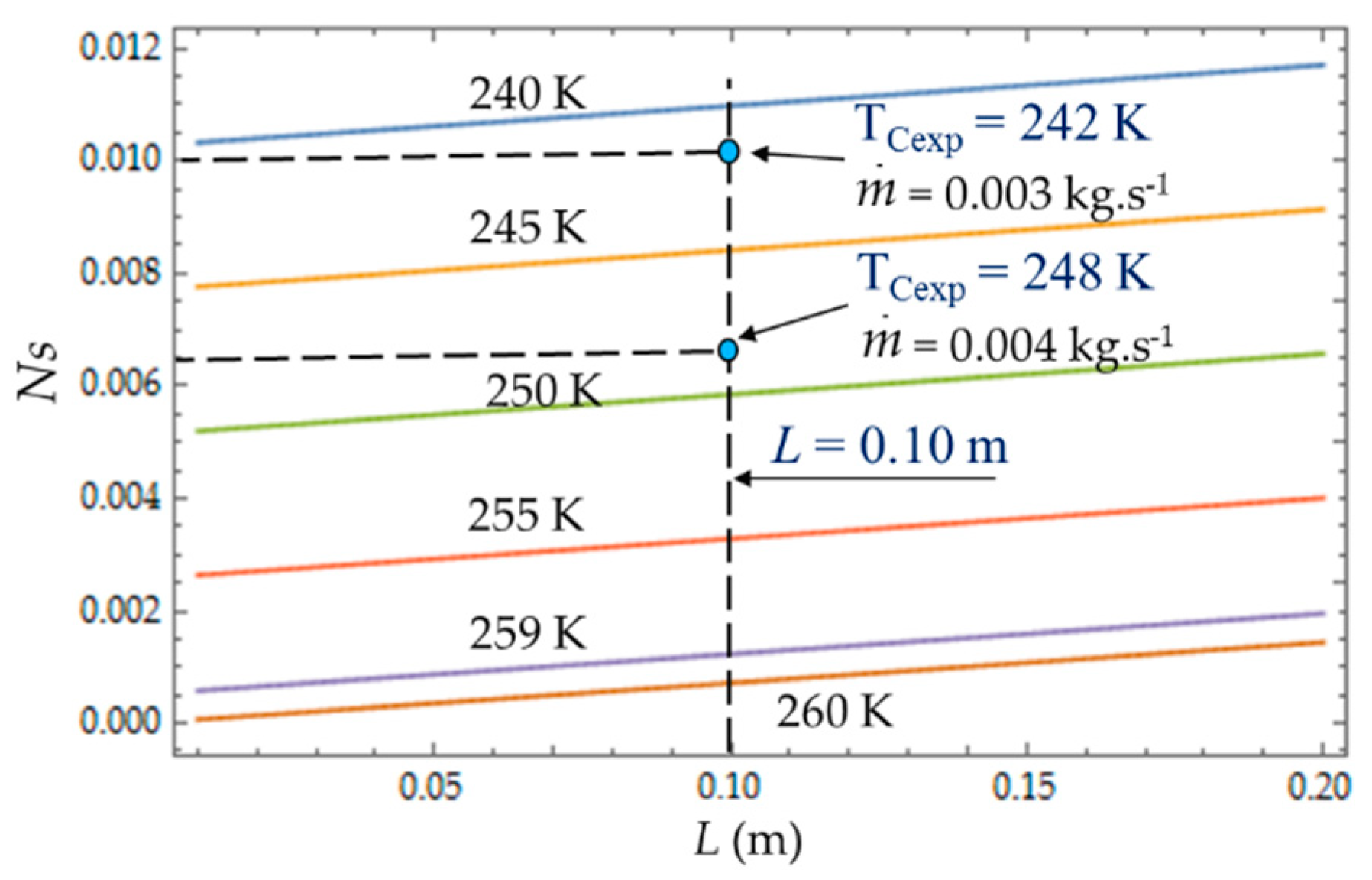
Figure 10 present the entropy generation parameters (N
S,
and φ) as functions of length (L) and hydraulic diameter (D
h) for fixed values of cold gas temperature (T
C). The entropy generation number (N
S) increases with the length L of the heat exchanger because of the increase in the fluid friction and pressure drop. For a given length, N
S (
Figure 8) increases when the temperature T
C decreases because the heat transfer and the entropy production increase. For each mass flow rate
of the cooling liquid, we measured the temperature T
C of the cold gas inside the expansion space of the refrigerator. For
= 0.003 kg.s
−1, this temperature is
TCexp = 242 K and it corresponds to the entropy generation number
NS ≈ 0.010, while the theoretical model provides a higher value
NS ≈ 0.011 (+10%) and a lower temperature
TC = 240 K. When the flow rate increases (
= 0.004 kg.s
−1), the pressure drop also logically increases, causing the decrease in
.
The irreversibility distribution ratio φ increases with the length L of the heat exchanger (
Figure 9). At given length L, the smallest values of φ correspond to the case for which the heat transfer dominates. We observe at L = 0.10 m (
Figure 9), an increase in φ as the mass flow rate
increases because the fluid frictions dominate, as was observed in the literature [
3,
22,
40].
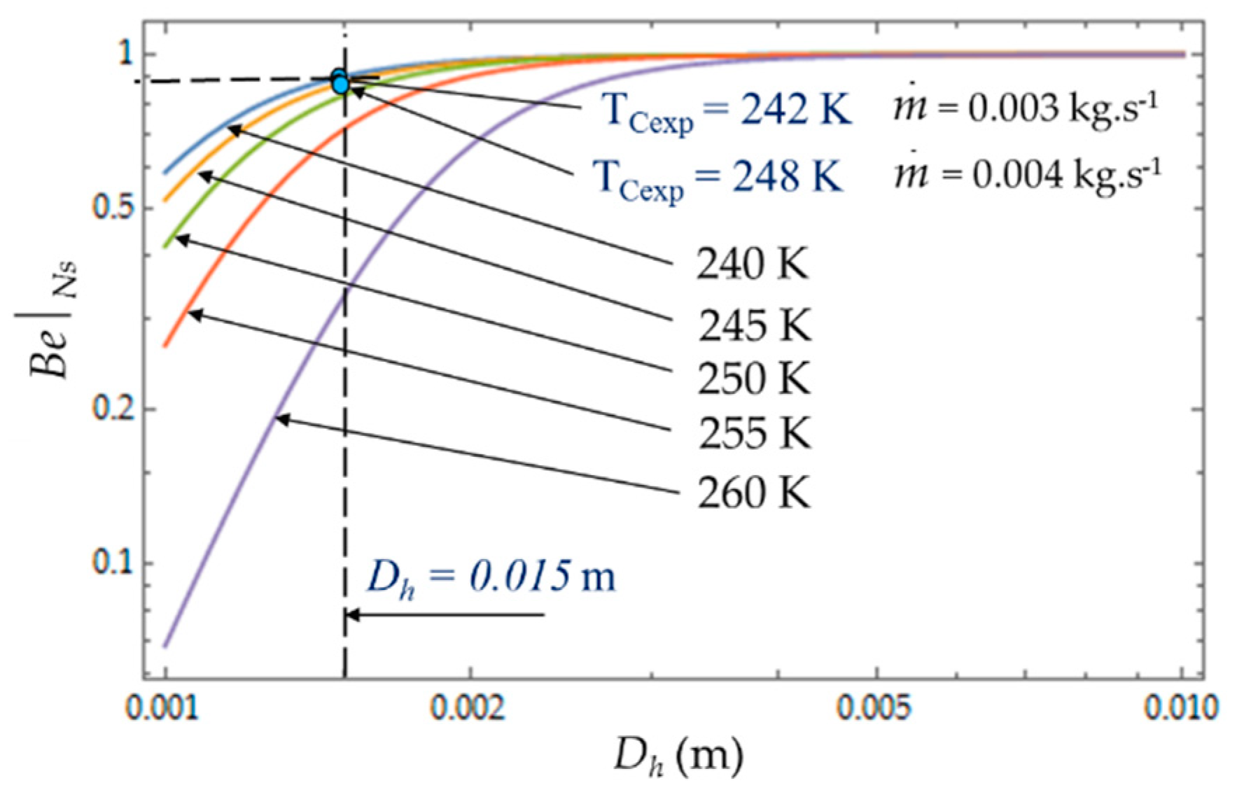
Figure 10 plots the evolution of
as a function of cold heat exchange length
L at different temperatures
TC. The limit
when the heat transfer dominates. At given mass flow rate
, for small values of hydraulic diameter (
Dh < 5 mm), the effect of fluid friction is more effective and
varies with great sensitivity to temperature
TC. For higher values of hydraulic diameter,
Dh > 5 mm, the heat transfer dominates fluid frictions regardless of the temperature
TC of the cold volume and, consequently,
ϕ → 0 (
Figure 11). The effects of the variation in the mass flows
and
are of the same amplitude in our experiments and show the dominance of the heat transfer on the fluid frictions (
and
ϕ → 0).
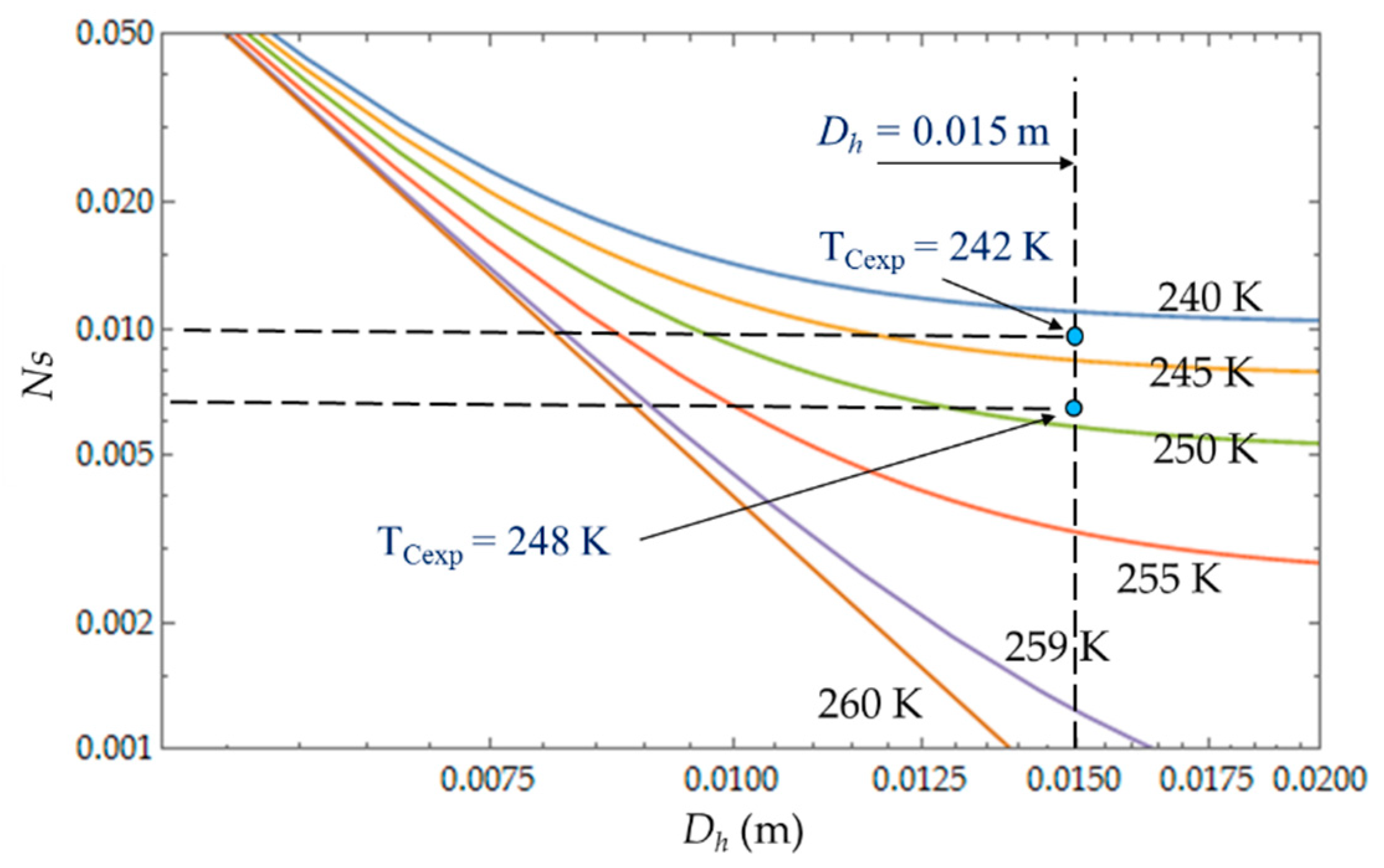
The heat transfer impacts the entropy generation rate
NS, which logically decreases with the temperature
TC, and the hydraulic diameter
Dh, corresponding to the dominance of the heat transfer irresversibilities over fluid losses (
Figure 12). That is what we observed with the two experimental temperatures
TCexp = 242 K and
TCexp = 248 K corresponding to the two mass flow rates
and
.
The objective is to reduce the degree of irreversibility of the refrigerator and to obtain small values of
NS [
16,
22,
33,
41]. This objective depends on the parameters temperature of the cold volume and hydraulic diameter. We observe that the properties of the refrigerant play an important role. When the temperature of the fluid is too low, the viscosity of the fluid and the pressure drops increase and
NS increases as well, which reduces the performance of the refrigerator. For large values of
Dh, the entropy generated by the fluid losses is no longer affected by the flow friction losses. Ns tends towards a constant (in our case, this phenomenon is quite obvious for the temperatures 240 K <
Tc < 250 K) and the irreversibility distribution ratio φ tends to zero (
Figure 11). The entropy generation rate
NS depends mainly on the part of the entropy due to heat transfers and then decreases as a function of temperature
TC and hydraulic diameter
Dh across a trade-off between fluid flow irreversibilities and heat transfer.
4.2. Effect of Coolant Mass Flow
As shown in Equations (4), (8) and (13), it appears that the greater the mass flow
, the higher the fluid frictions and pressure drop. As a result, at a fixed mass flow, both entropy generation rate
NS and irreversibility distribution ratio
ϕ increase with the heat transfer (
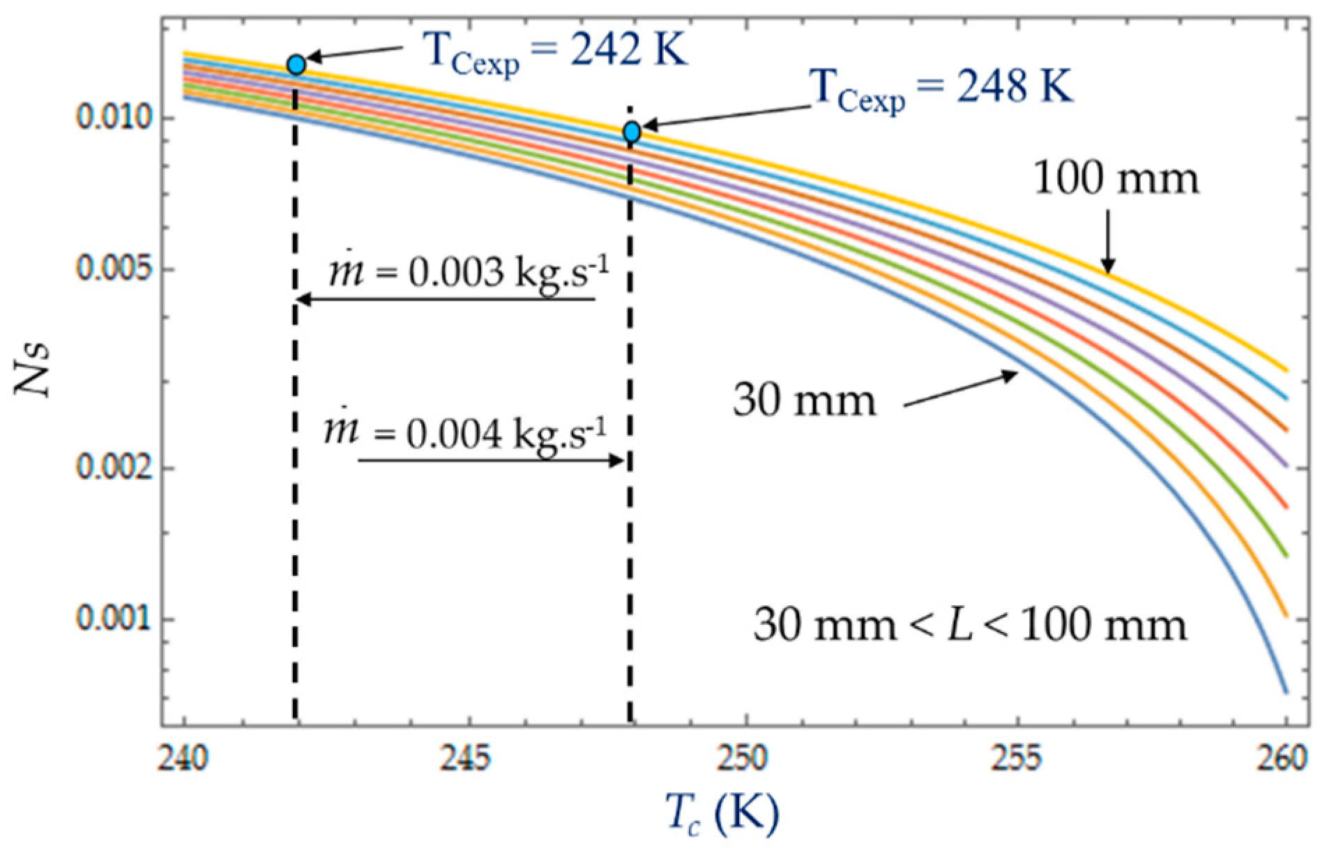
Figure 13). Effectively, at low temperatures (
TC = 240 K), the heat transfer from the coolant at mean bulk temperature
Tmb = (
Ti +
To)/2 to the gas is higher than at high temperatures (
TC = 260 K) and
Ns presents highest variations. This observed for the two experimental temperatures
TCexp = 242 K and
TCexp = 248 K corresponding to the mass flow rates
= 0.003 kg.s
−1 and
= 0.004 kg.s
−1, respectively. Consequently, at a low temperature (
TC = 240 K) and small cooling flow rate, the irreversibility distribution
ϕ and Bejan number
confirm that heat transfer dominates fluid frictions (
Figure 14 and
Figure 15). These phenomena are verified for both refrigerant flow rates
= 0.003 kg.s
−1 and
= 0.004 kg.s
−1.
At given temperatures Tc with 240 K < TC < 255 K, and for low mass flow rates, < 0.10, the trend in the evolution of the Bejan number shows the dominance of heat transfer over viscous friction and → 1. Experimental tests with = 0.003 kg.s−1 and = 0.004 kg.s−1 are thus found in this working area of the refrigerating machine.
4.3. Effect of Cold Gas Temperature TC
The temperature
TC of the cold gas inside the expansion volume is measured when the Stirling refrigerator runs at a steady rotational speed ω. For given inlet and outlet temperatures,
Ti = 300 K and
To = 260 K respectively, the heat transfer exchanged with the collant at mean bulk temperature decreases with the coolant temperature (
Figure 16). This figure shows that, at the given cold gas temperature
Tc, the entropy generation rate
NS increases with the length
L of the heat exchanger due to an increased pressure drop caused by viscous friction along the heat exchanger confirming the dominance of pressure drop [
29,
42]. As the amplitudes of gas temperature increase, both heat transfer exchanged with the coolant fluid at mean bulk temperature and irreversibility distribution ratio
φ increase (
Figure 17). At low temperatures (e.g., 240 K), the viscosity and the Prandlt number of the liquid increase sharply, with a factor around 7 between 243 K and 263 K, and the friction losses become high even at low flow rates. For the limit temperature
Tc → 260 K, at fixed mass flow
, the heat transfer would require an infinite quantity or a perfect heat exchanger efficiency and that is why the irreversibility distribution ratio
φ rises sharply as the temperature approaches the limit
Tc → 260 K and would tend to infinity for
Tc = 260 K.
5. Conclusions
We have developed an analysis of the entropy generation rate inside a cold heat exchanger of a Stirling refrigerator by examining the behavior of three criteria: the adimensionless entropy ratio NS, the irreversibility distribution ratio φ and the Bejan number based on the adimensionless entropy ratio NS,∆T and NS,∆P corresponding to the heat transfer and fluid friction irreversibilities, respectively.
The cold heat exchanger is a double-pipe type heat exchanger made up of two concentric circular tubes. The incompressible coolant liquid flows continuously, with a mass flow rate, through the annular passage, under the temperature and pressure gradients, respectively. The other fluid is the working gas (Nitrogen) of the Stirling refrigerator and it flows alternatively (corresponding to the rotational frequency of the machine) at constant temperature TC in the inner tube corresponding to the cylinder of the machine.
The cold heat exchanger transfers heat from a gas to a coolant liquid in the temperature range (240–300 K) and the efficiency of this operation is a result of the competition between heat transfer and fluid flow irreversibilities. We have carried out experiments with two mass flow rates = 0.003 kg.s−1 and = 0.004 kg.s−1 and showed the dominance of heat transfer over viscous friction in the cold heat exchanger, which presents a hydraulic diameter Dh = 0.015 m and a length L = 0.10 m.
The aim of the analysis was to understand the impact of hydraulic diameter Dh, length L, coolant mass flow and cold gas temperature TC on these three criteria. It could be shown that, to ensure a minimal entropy production ratio NS, it is necessary to minimize the fluid friction irreversibilities (NS,∆P). Experimental results have shown the trade-off between fluid flow irreversibilities and heat transfer. We showed that large characteristic length and small hydraulic diameter generate large entropy production especially at low mean temperatures because of the high value of the coolant liquid (mix water/ethylene–glycol) viscosity increasing the fluid friction.
Our analysis needs to be further improved on these different points:
- -
Develop a second law analysis based on a heat exchanger submitted to periodic flows;
- -
Investigate other cold exchanger geometries with a larger hydraulic diameter and length and different mass flow rates;
- -
Perform exergetic and thermoeconomic analysis in order to define new indicators.


