Research on a Simplified Model of an Aluminum Vapor Chamber in a Heat Dissipation System


Abstract
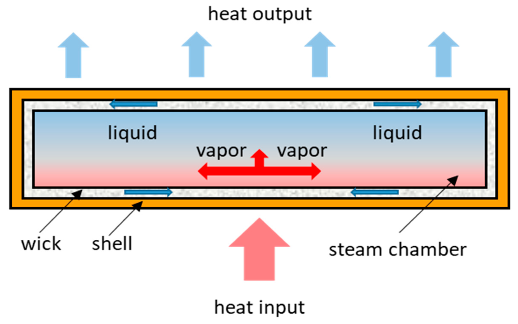
1. Introduction
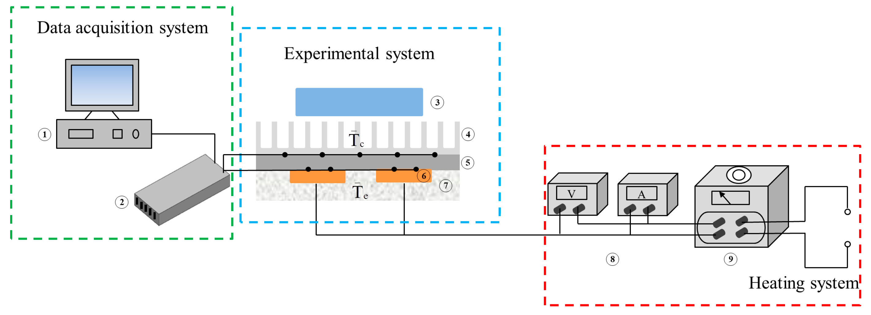
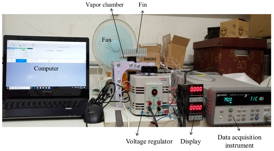
2. Experimental Facility
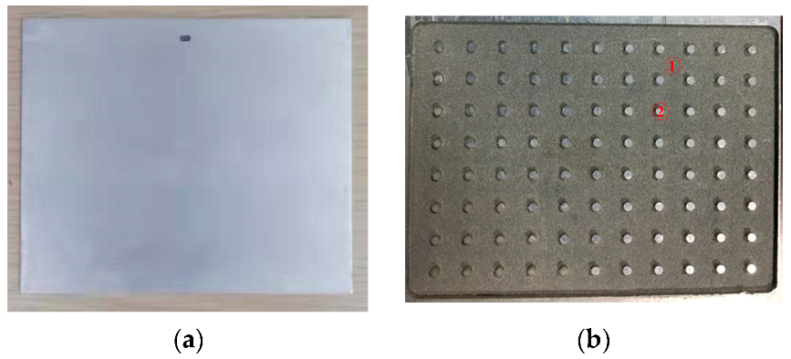
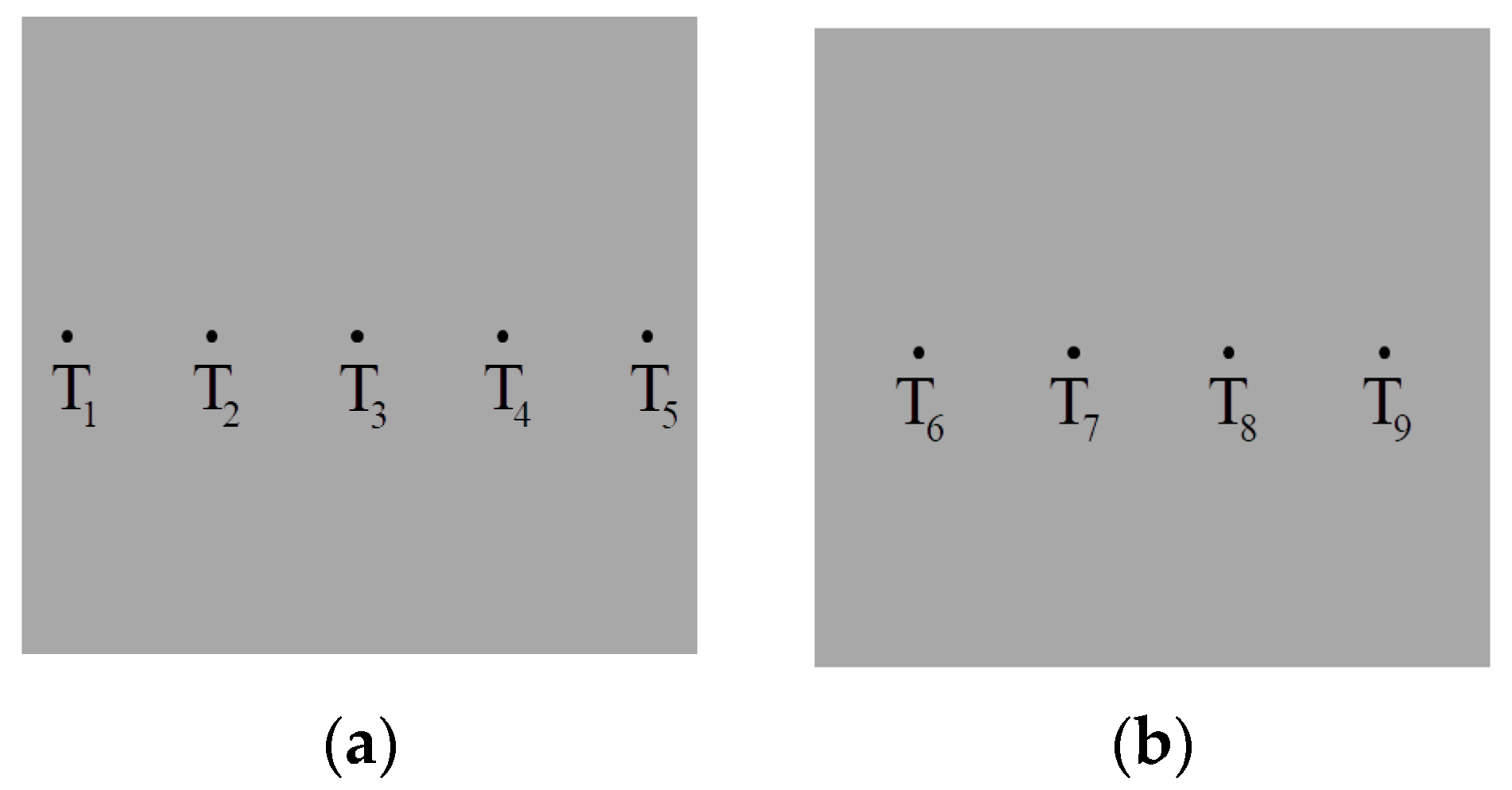
2.1. Test Section
2.2. Data Analysis
2.3. Uncertainty Analysis
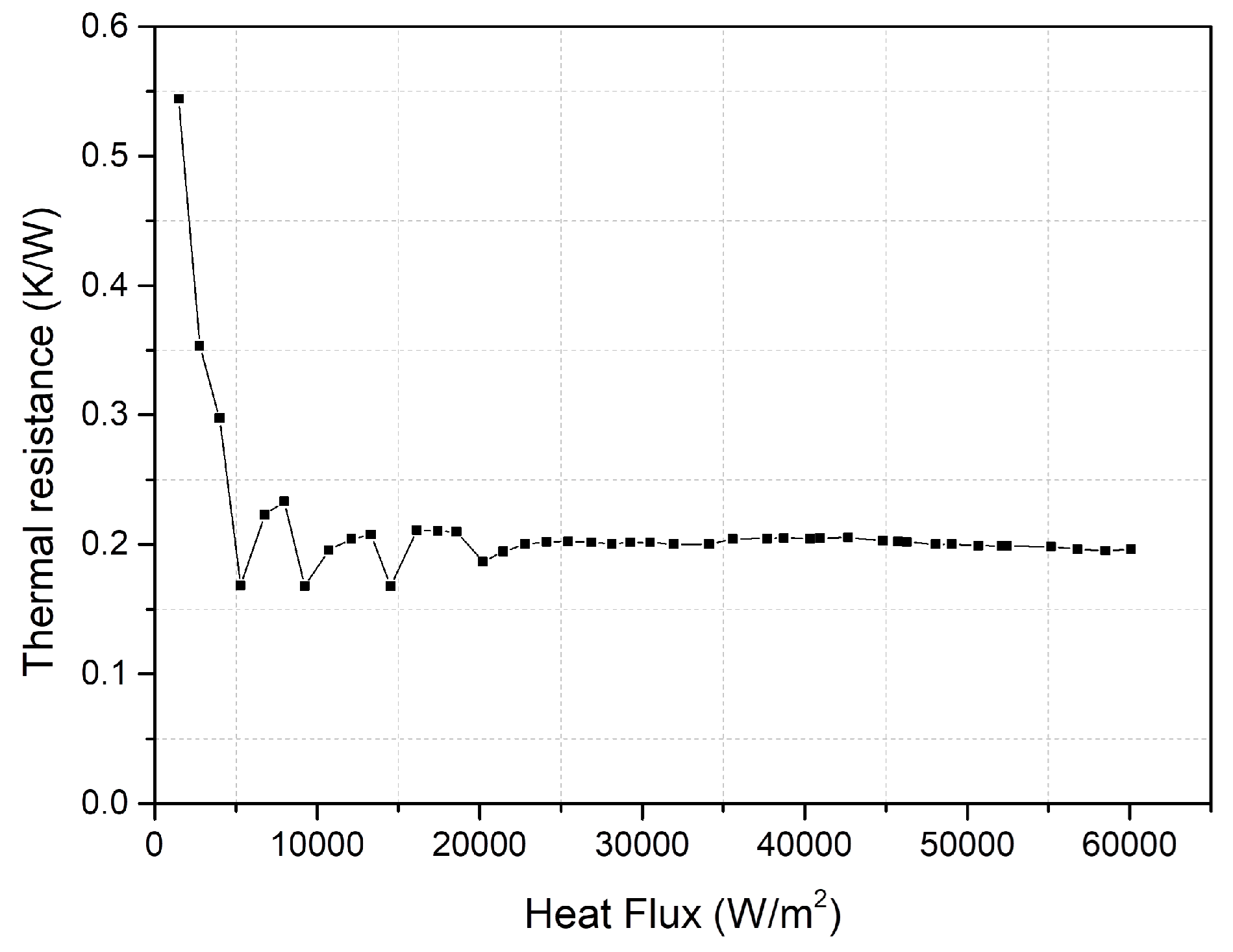
2.4. Experimental Result
3. Analysis and Modeling
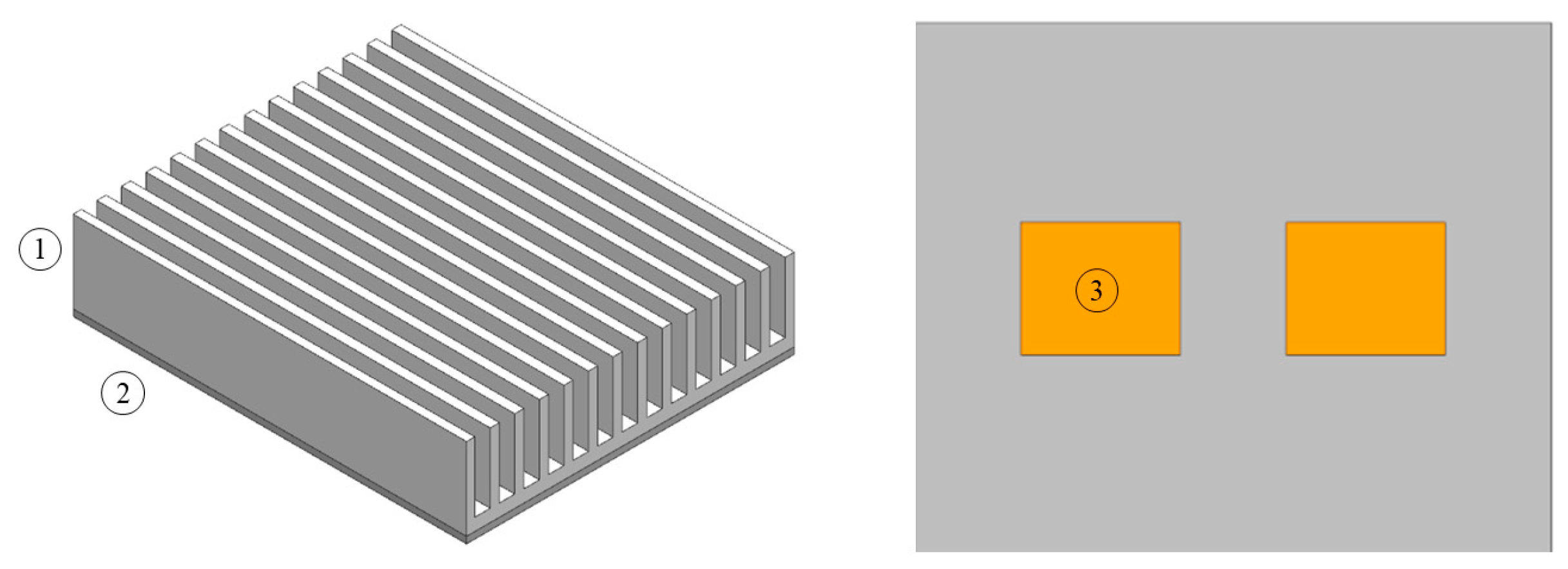
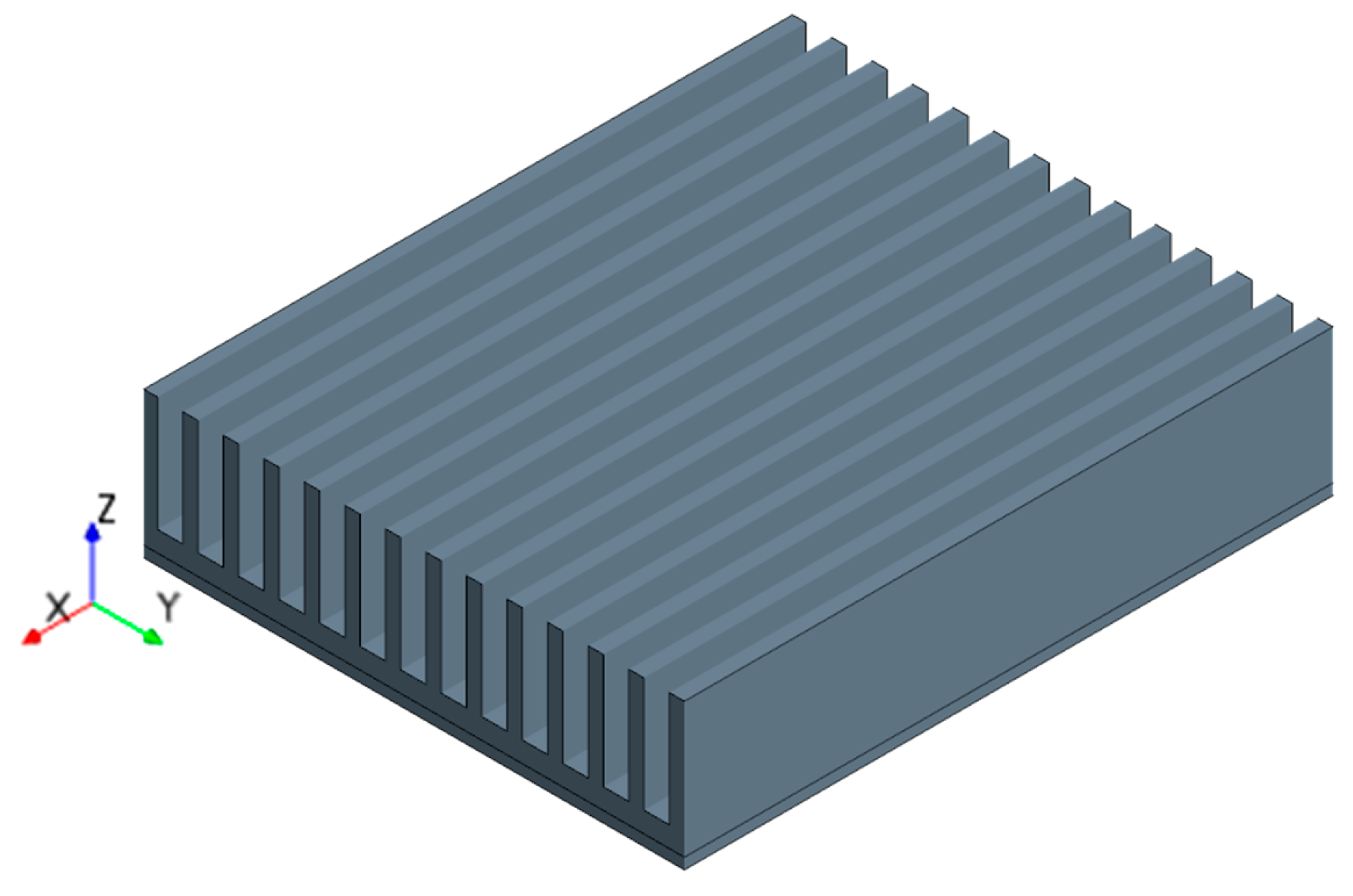
3.1. Geometric Model
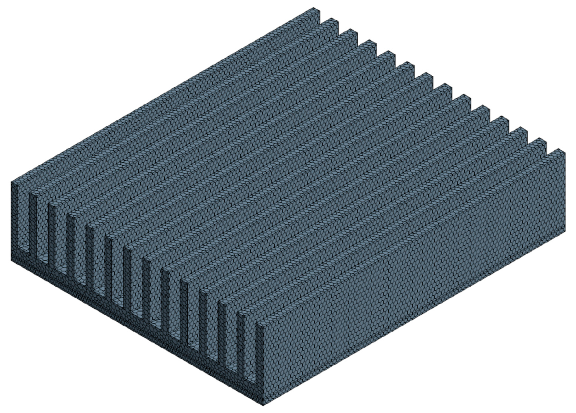
3.2. Mesh Model
3.3. Physical Model
4. Results and Discussion
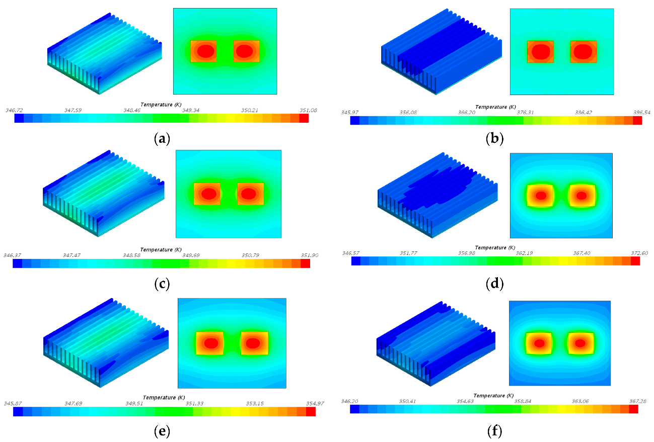
4.1. Results Analysis
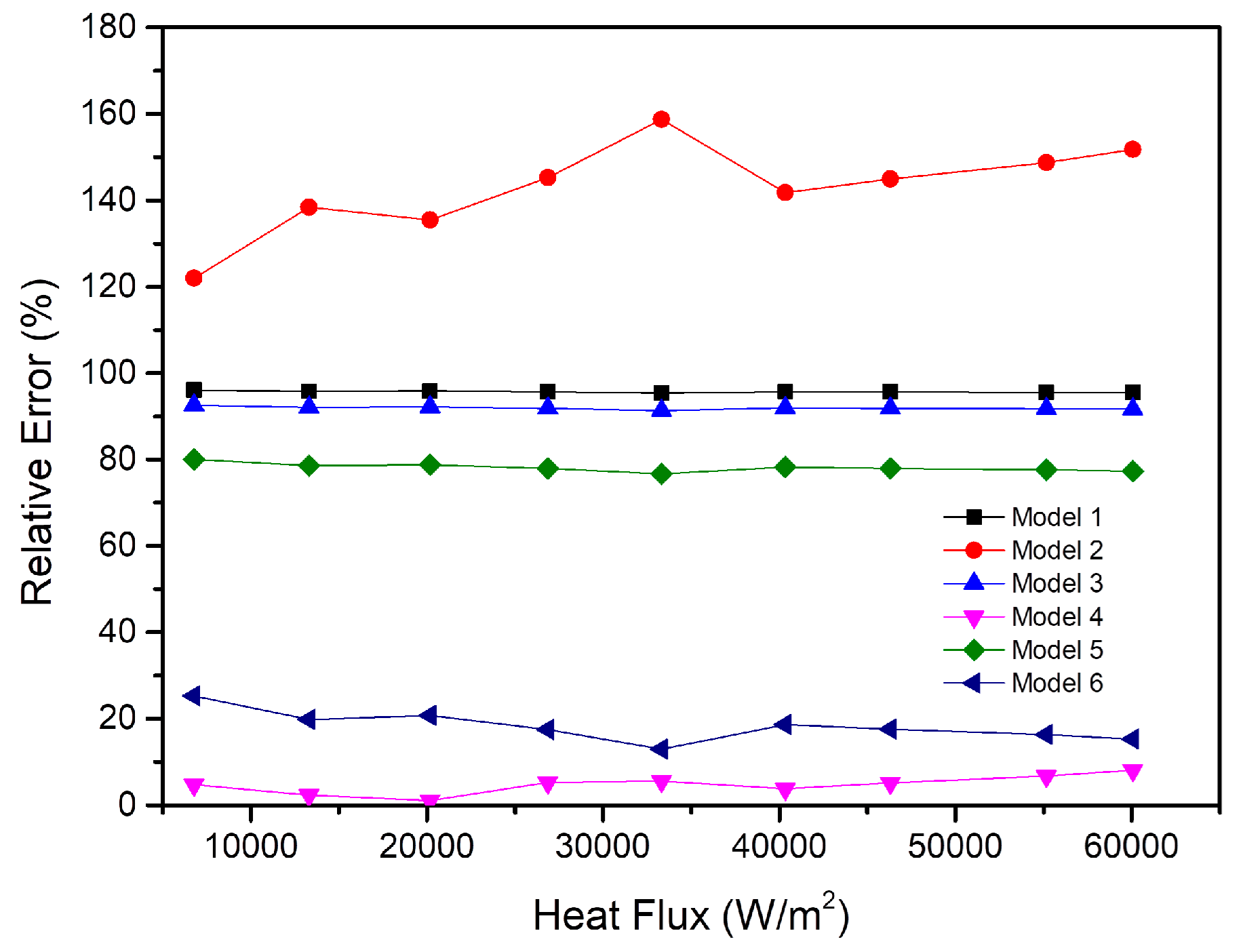
4.2. Results Verification
5. Conclusions
- (1)
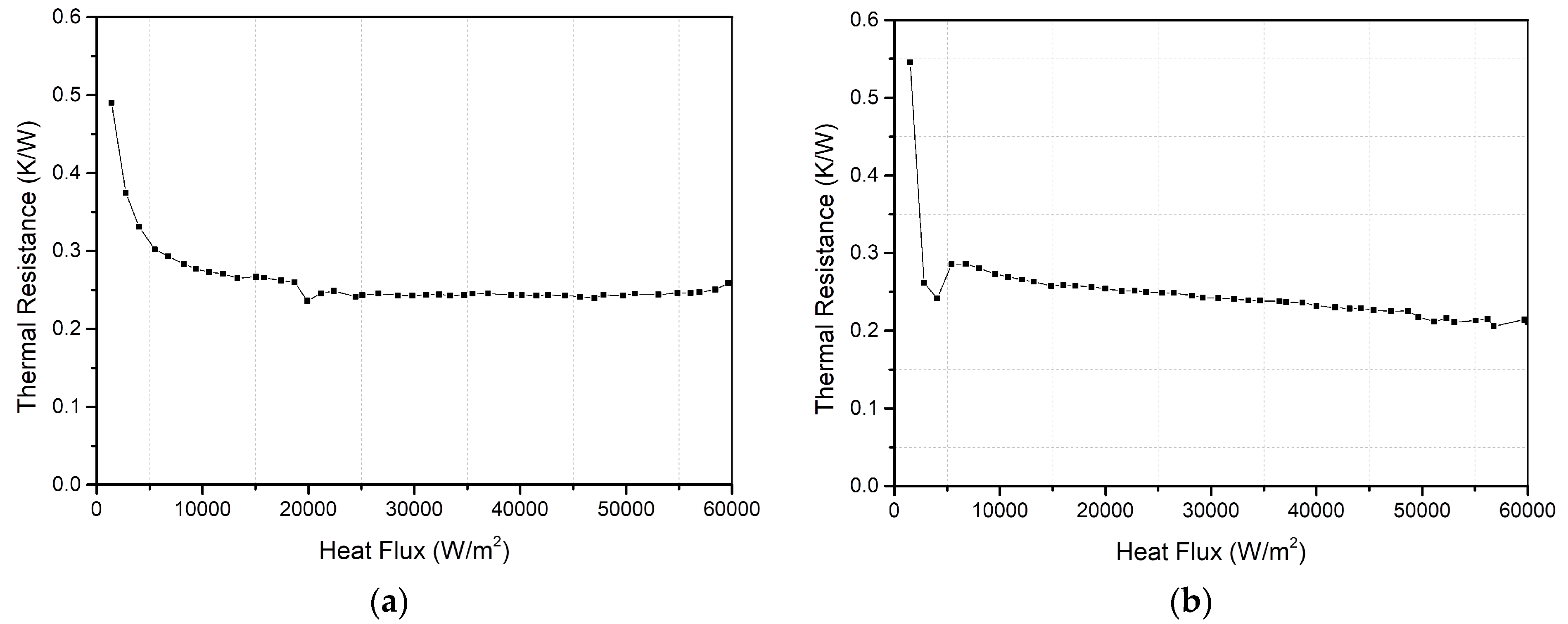
- As the heat flux density increases, the thermal resistance of the vapor chamber is smaller and the thermal performance is better. Within the working temperature range of electronic components, the thermal resistance of the vapor chamber is a constant value of 0.2 K/W, and there is no dry-out phenomenon.
- (2)
- By numerically simulating the six simplified models, the thermal resistance of the six models is analyzed. Then, the conclusion that simplifying the vapor chamber into the shell and the other part is suitable compared to other models is finally obtained.
- (3)
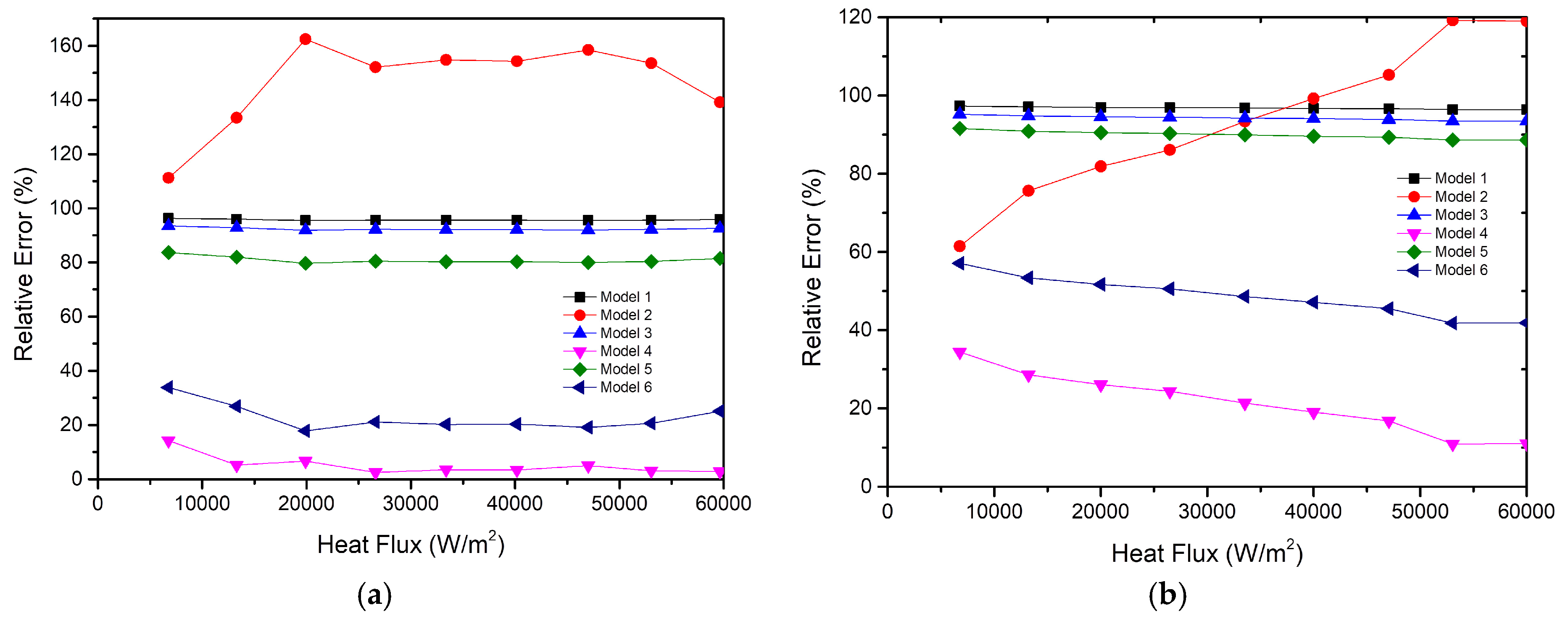
- Although the simplified Model 4 is the most suitable model of the vapor chamber under different test conditions, the results show that the accuracy of the model decreases with more heat sources.
- (4)
- By analyzing simplified models of the vapor chamber under different testing conditions, the most suitable and general simplified Model 4 in the heat dissipation system is obtained, which is very significant for industrial thermal design.
Author Contributions
Funding
Acknowledgments
Conflicts of Interest
References
- Ternet, F.; Louahlia-Gualous, H.; Masson, S.L. Impact of microgroove shape on flat miniature heat pipe efficiency. Entropy 2018, 20, 44. [Google Scholar] [CrossRef]
- Lai, A.; Gillot, C. Thermal characterization of flat silicon heat pipes. In Proceedings of the IEEE Semiconductor Thermal Measurement and Management Symposium, San Jose, CA, USA, 11 March 2004. [Google Scholar]
- Yao, F.; Miao, S.S. An experimental study of an anti-gravity vapor chamber with a tree-shaped evaporator. Appl. Therm. Eng. 2018, 141, 1000–1008. [Google Scholar] [CrossRef]
- Liu, W.; Yi, P. The performance of the vapor chamber based on the plant leaf. Int. J. Heat Mass Transf. 2016, 98, 746–757. [Google Scholar] [CrossRef]
- Yu, X.; Zhang, L. Heat transfer of an IGBT module integrated with a vapor chamber. J. Electron. Packag. 2011, 133, 011008. [Google Scholar] [CrossRef]
- Lefèvre, F.; Rullière, R. Prediction of the temperature field in flat plate heat pipes with micro-grooves-Experimental validation. Int. J. Heat Mass Transf. 2008, 51, 4083–4094. [Google Scholar] [CrossRef]
- Liu, W.; Gou, J. The experimental investigation of a vapor chamber with compound columns under the influence of gravity. Appl. Therm. Eng. 2018, 140, 131–138. [Google Scholar] [CrossRef]
- Hsieh, J.C.; Lin, D.T. An experimental study on the compatibility of acetone with aluminum flat-plate heat pipes. Heat Mass Transf. 2014, 50, 1525–1533. [Google Scholar] [CrossRef]
- Koito, Y.; Imura, H. Numerical analysis and experimental verification on thermal fluid phenomena in a vapor chamber. Appl. Therm. Eng. 2006, 26, 1669–1676. [Google Scholar] [CrossRef]
- Chen, Y.S.; Chien, K.H. Numerical simulation of a heat sink embedded with a vapor chamber and calculation of effective thermal conductivity of a vapor chamber. Appl. Therm. Eng. 2009, 29, 2655–2664. [Google Scholar] [CrossRef]
- Velardo, J.; Singh, R. An investigation into the effective thermal conductivity of vapour chamber heat spreaders. Energy Procedia 2017, 110, 256–261. [Google Scholar] [CrossRef]
- Velardoa, J.; Date, A.; Singh, R.; Nihill, J.; Date, A.; Phan, T.L. On the effective thermal conductivity of the vapour region in vapour chamber heat spreaders. Int. J. Heat Mass Transf. 2019, 145, 118797. [Google Scholar] [CrossRef]
- Chen, L.; Deng, D. Development and thermal performance of a vapor chamber with multiartery reentrant microchannels for high-power LED. Appl. Therm. Eng. 2019, 17, 131–138. [Google Scholar]
- Zeng, J.; Zhang, S. Experimental investigation on thermal performance of aluminum vapor chamber using micro-grooved wick with reentrant cavity array. Appl. Therm. Eng. 2018, 130, 185–194. [Google Scholar] [CrossRef]
- Naphon, P.; Wiriyasart, S. Study on the vapor chamber with refrigerant R-141b as working fluid for HDD cooling. Int. Commun. Heat Mass Transf. 2012, 39, 1449–1452. [Google Scholar] [CrossRef]
- Attia, A.A.; El-Assal, B.T.A. Experimental investigation of vapor chamber with different working fluids at different charge ratios. Ain Shams Eng. J. 2012, 3, 289–297. [Google Scholar] [CrossRef]
- He, B.; Wei, M. Experiments on the ultrathin silicon vapor chamber for enhanced heat transfer performance. In Proceedings of the 15th IEEE Intersociety Conference on Thermal and Thermomechanical Phenomena in Electronic Systems in Electronic Systems, Las Vegas, NV, USA, 31 May–2 June 2016. [Google Scholar]
- Xuan, Y.; Hong, Y. Investigation on transient behaviors of flat plate heat pipes. Exp. Therm. Fluid Sci. 2004, 28, 249–255. [Google Scholar] [CrossRef]
- Ranjan, R.; Murthy, J.Y. A numerical model for transport in flat heat pipes considering wick microstructure effects. Int. J. Heat Mass Transf. 2011, 54, 153–168. [Google Scholar] [CrossRef]
- Xiao, B.; Faghri, A. A three-dimensional thermal-fluid analysis of flat heat pipes. Int. J. Heat Mass Transf. 2008, 51, 3113–3126. [Google Scholar] [CrossRef]
- Sobhan, C.B.; Garimella, S.V. A computational model for the transient analysis of flat heat pipes. In Proceedings of the Conference on Thermal and Thermomechanical Phenomena in Electronic Systems, Las Vegas, NV, USA, 23–26 May 2000. [Google Scholar]
- Elnaggar, M.H.; Abdullah, M.Z. Experimental analysis and FEM simulation of finned U-shape multi heat pipe for desktop PC cooling. Energy Convers. Manag. 2011, 52, 2937–2944. [Google Scholar] [CrossRef]
- Wang, S.; Chen, J. Effect of evaporation section and condensation section length on thermal performance of flat plate heat pipe. Appl. Therm. Eng. 2011, 31, 2367–2373. [Google Scholar] [CrossRef]
- Zhang, D.; Tao, H. Numerical simulation investigation on thermal performance of heat pipe flat-plate solar collector. Appl. Therm. Eng. 2017, 118, 113–126. [Google Scholar] [CrossRef]
- Li, D.; Zhang, G.Q. Numerical simulation on heat pipe for high power LED multi-chip module packaging. In Proceedings of the International Conference on Electronic Packaging Technology and High Density Packaging, Beijing, China, 10–13 August 2009. [Google Scholar]
- Zhang, Z.; Wei, K. Experimental and numerical study of a passive thermal management system using flat heat pipes for lithium-ion batteries. Appl. Therm. Eng. 2019, 11, 114660. [Google Scholar] [CrossRef]
- Anderson, A.M. Experimental methods for engineers. Exp. Therm. Fluid Sci. 1994, 9, 250–255. [Google Scholar] [CrossRef]
- Ababneh, M.T.; Gerner, F.M. Thermal-fluid modeling for high thermal conductivity heat pipe thermal ground planes. J. Thermophys. Heat Transf. 2014, 28, 270–278. [Google Scholar] [CrossRef]


| Simplified Models | Reference |
|---|---|
| Anisotropic entire region | [10,24,26] |
| Isotropic entire region | [11,23,25,27] |
| The entire region divided into the wall region, vapor region, and wick region | [12] |
| Measured Value | Calculated Value | ||
|---|---|---|---|
| Parameter | Uncertainty | Parameter | Uncertainty |
| 0.25 K | 1.47% | ||
| 1% | |||
| 1% | |||
| Base Size of the Grid | Number of the Grid | Temperature Difference between Evaporation and Condensation Surface | Thermal Resistance |
|---|---|---|---|
| 1 mm | 21,6870 | 1.104300 | 0.498510293 |
| 2 mm | 130,371 | 1.095600 | 0.494582882 |
| 4 mm | 123,065 | 1.141900 | 0.515483929 |
| 8 mm | 37,517 | 1.572700 | 0.709958469 |
| Model | Shell | Wick | Steam Chamber |
|---|---|---|---|
| Model 1 | in all directions | ||
| Model 2 | in X directions, in Y directions, in Y directions | ||
| Model 3 | Aluminum alloy | in all directions | |
| Model 4 | Aluminum alloy | in X directions, in Y directions, in Y directions | |
| Model 5 | Aluminum alloy | in all directions | |
| Model 6 | Aluminum alloy | in X directions, in Y directions, in Y directions | |
| Model | Thermal Resistance |
|---|---|
| model 1 | 0.0088 |
| model 2 | 0.4946 |
| model 3 | 0.01651 |
| model 4 | 0.2123 |
| model 5 | 0.04451 |
| model 6 | 0.16644 |
© 2019 by the authors. Licensee MDPI, Basel, Switzerland. This article is an open access article distributed under the terms and conditions of the Creative Commons Attribution (CC BY) license (http://creativecommons.org/licenses/by/4.0/).
Share and Cite
Han, S.; Yang, L.; Tian, Z.; Yuan, X.; Lu, H. Research on a Simplified Model of an Aluminum Vapor Chamber in a Heat Dissipation System. Entropy 2020, 22, 35. https://doi.org/10.3390/e22010035
Han S, Yang L, Tian Z, Yuan X, Lu H. Research on a Simplified Model of an Aluminum Vapor Chamber in a Heat Dissipation System. Entropy. 2020; 22(1):35. https://doi.org/10.3390/e22010035
Chicago/Turabian StyleHan, Shuang, Lixin Yang, Zihao Tian, Xiaofei Yuan, and Hongyan Lu. 2020. "Research on a Simplified Model of an Aluminum Vapor Chamber in a Heat Dissipation System" Entropy 22, no. 1: 35. https://doi.org/10.3390/e22010035
APA StyleHan, S., Yang, L., Tian, Z., Yuan, X., & Lu, H. (2020). Research on a Simplified Model of an Aluminum Vapor Chamber in a Heat Dissipation System. Entropy, 22(1), 35. https://doi.org/10.3390/e22010035