1. Introduction
In security communication, the cryptogram generator is a key device. It is showed that in chaotic security communications, this cryptogram generator can be a chaotic system. In chaotic security communications, the utility of the chaotic system is “encryption”, thus it is valuable to construct a proper chaotic system for chaotic security communication. A time delayed chaotic system has a simple structure and a hyperchaotic attractor in phase space, which provides a higher level of security in chaotic secure communications [
1,
2,
3,
4]. Therefore the design and implementation of a time-delayed chaotic system is of high practical importance for increasing the safety of secure communication.
FPAA (Field Programmable Analog Array) is a dynamically programmable Analog Signal Processor device. It has integrator, comparator, amplifier, inverter, multiplier, delay and other blocks. These blocks are constructed from a combination of conventional and switched capacitor circuit elements and are programmed by a host processor [
5]. We can easily and flexibly use FPAA’s programming software to design an analog circuit including time-delay chaotic system through the combination of blocks. Then these analog circuits pre-constructed can be realized by being downloaded to the FPAA development board in real time. Therefore, this programmable device is easier, more efficient and more economical than using individual operational amplifiers, resistors, capacitances, analog multipliers and other discrete components used for implementing analog circuit systems.
FPAA has become more and more popular recently [
6,
7,
8,
9]. Caponetto used FPAAs to design and implement a fully programmable Chua’s circuit and highlight several advantages of the approach: The design and implementation phases are very simple, and the circuit is totally programmable [
10]. Further, Recai Kilic realized FPAA-based Chua’s circuit models and jerk circuit using different nonlinear functions in a programmable and reconfigurable form [
11,
12]. What’s more, Recai Kilic introduced a universal approach to design and implement programmable analog non-time-delay chaotic systems based on FPAA [
13]. After that, Fatma Yildirim Dalkiran and J. C. Sprott realized a fourth-order hyperjerk system based on FPAA [
14]. Chunbiao Li designed and implemented chaotic systems with complete amplitude control and constructed infinitely many attractors in a programmable chaotic circuit based on FPAA [
15,
16]. But the above researchers had not designed and implemented time-delay chaotic systems based on the FPAA. Further, time-delayed chaotic systems can provide a higher level of security in chaotic secure communications compared with non-time-delay chaotic systems, so the design and implementation of a time-delayed chaotic circuit based on FPAA can be very helpful for researchers of chaos secure communication.
Therefore, in this paper, we aim to introduce a universal approach to design and implement programmable analog time-delay chaotic systems based on FPAA. In this context, firstly the design procedure of a FPAA device will be given and then FPAA-based design examples including autonomous and non-autonomous time-delay chaotic circuit models will be introduced. At the same time, we further analyze Shannon entropy and Lyapunov exponents of time series outputs by circuit and simulation systems. We hope that these design notes will be a useful practical guide for researchers who wish to experimentally study time-delay chaotic systems.
2. FPAA-Based System Designs
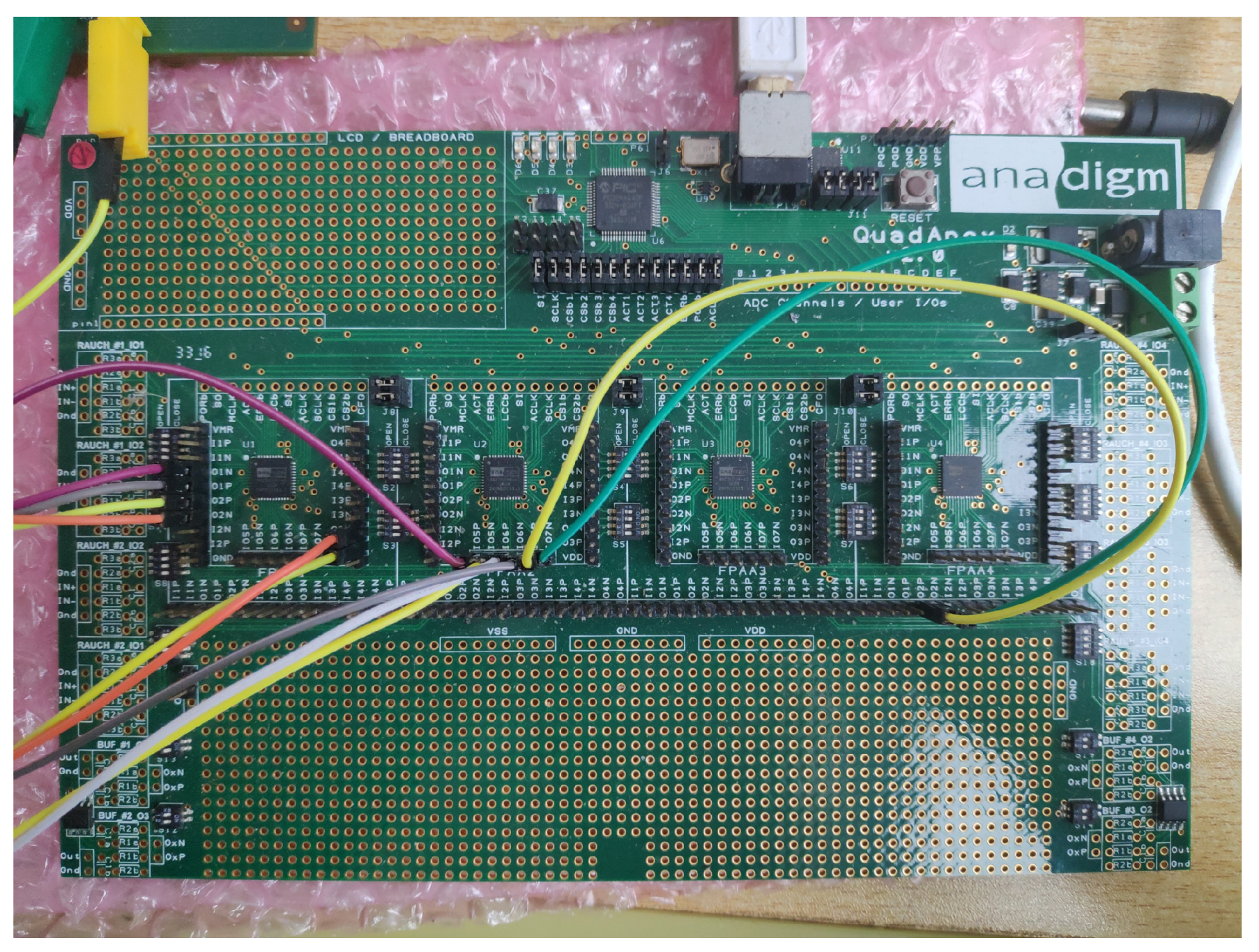
Here in this paper we use the newest integrated circuit technique of FPAA to realize time-delay chaotic systems. A FPAA development software named AnadigmDesigner2 was used to design time-delay systems in Windows. An Anadigm QuadApex development board shown in
Figure 1 with four AN231E04 chips was used to construct a circuit implementation of time-delay chaotic system.
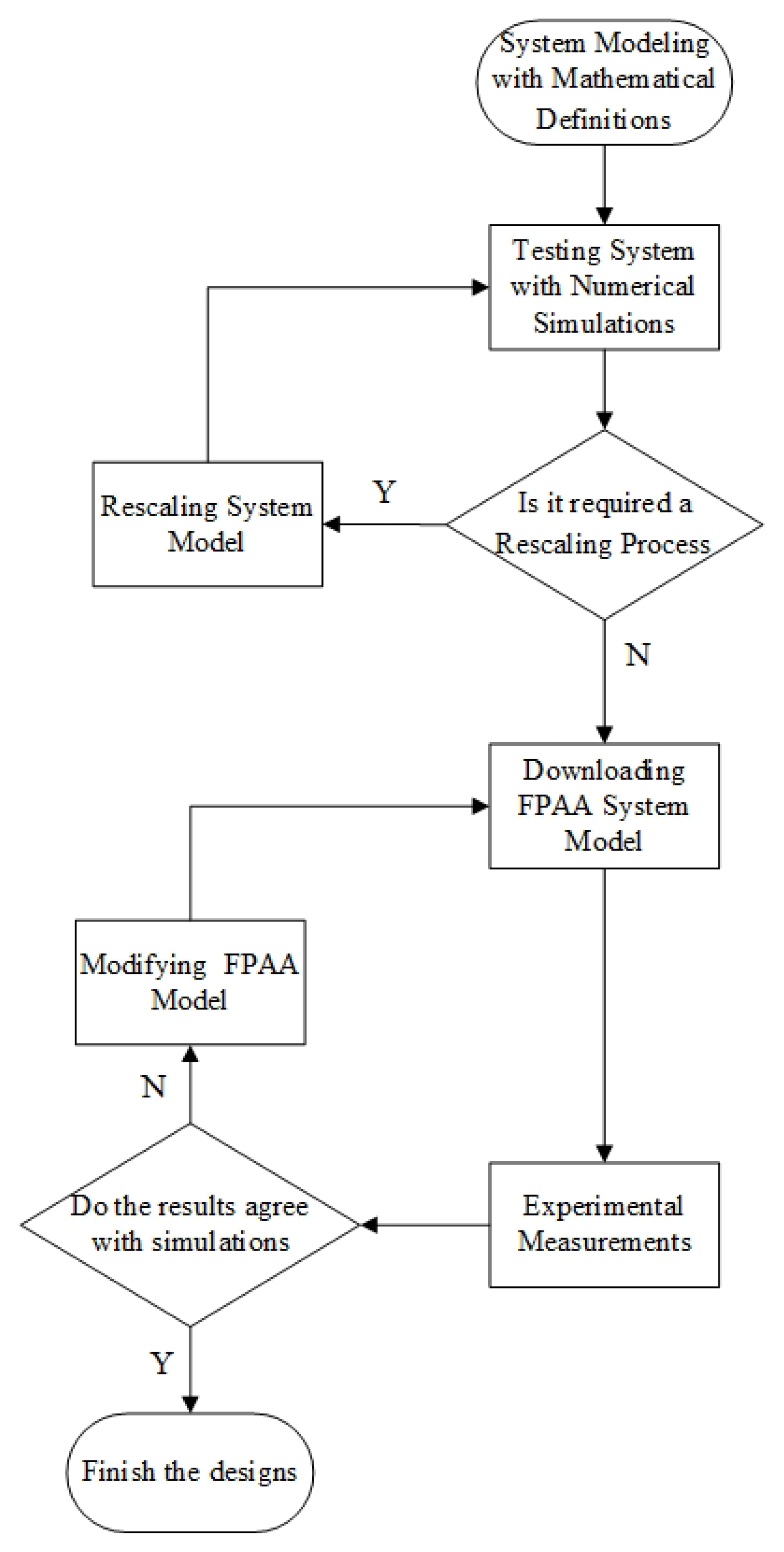
Figure 2 shows the basic flow chart of the FPAA designs. The analog signals of FPAA are limited to the range −3 V to +3 V. Therefore, we test the system with the numerical simulation before using the FPAA design system. Then we decide to rescale the system or not according to the simulation results. If there is something noticeable, we usually use matlab to simulate the system because the simulation tool of FPAA is too slow and the simulation time is too short. Then the system is designed in the FPAA design software, which is similar to the Simulink module of matlab. After setting up the circuit, the configuration information will be downloaded to the FPAA development board by clicking the download button in the software. The experimental results are compared with the simulation results, and if the results are satisfactory, the implementation is finished, otherwise FPAA modeling needs to be modified.
3. FPAA-Based Time-Delay Chaotic System Realizations
3.1. Autonomous Time-Delay Ikeda System
Ikeda system is a one-order autonomous time-delay chaotic system [
17]. It describes the phase shift in nonlinear optics, and presents a variety of periodic bifurcation and chaotic behaviors. The Ikeda system is one of the few delayed chaotic systems that have been studied deeply. Ikeda’s system is defined by the following state equation:
where
x denote the state variables of the system,
and
are system parameters and
represents the delay time which plays an important role in the system’s chaos mechanism. These parameters are determined as
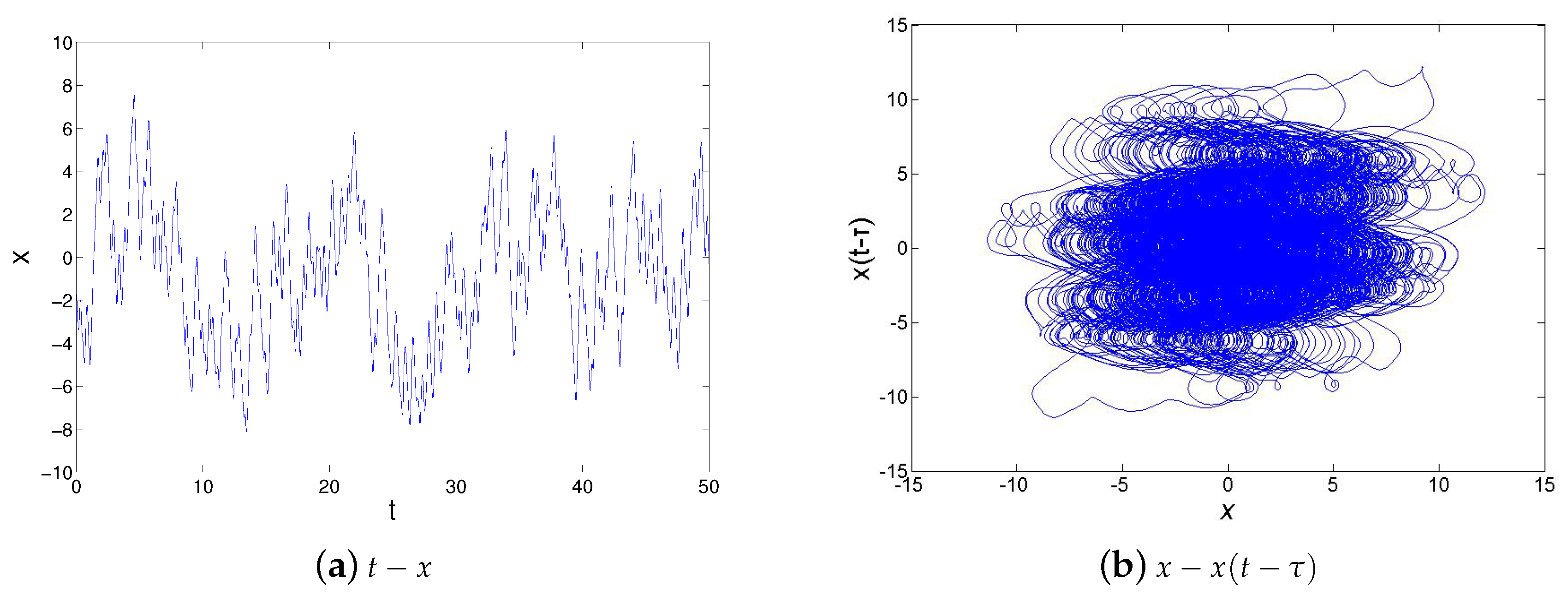
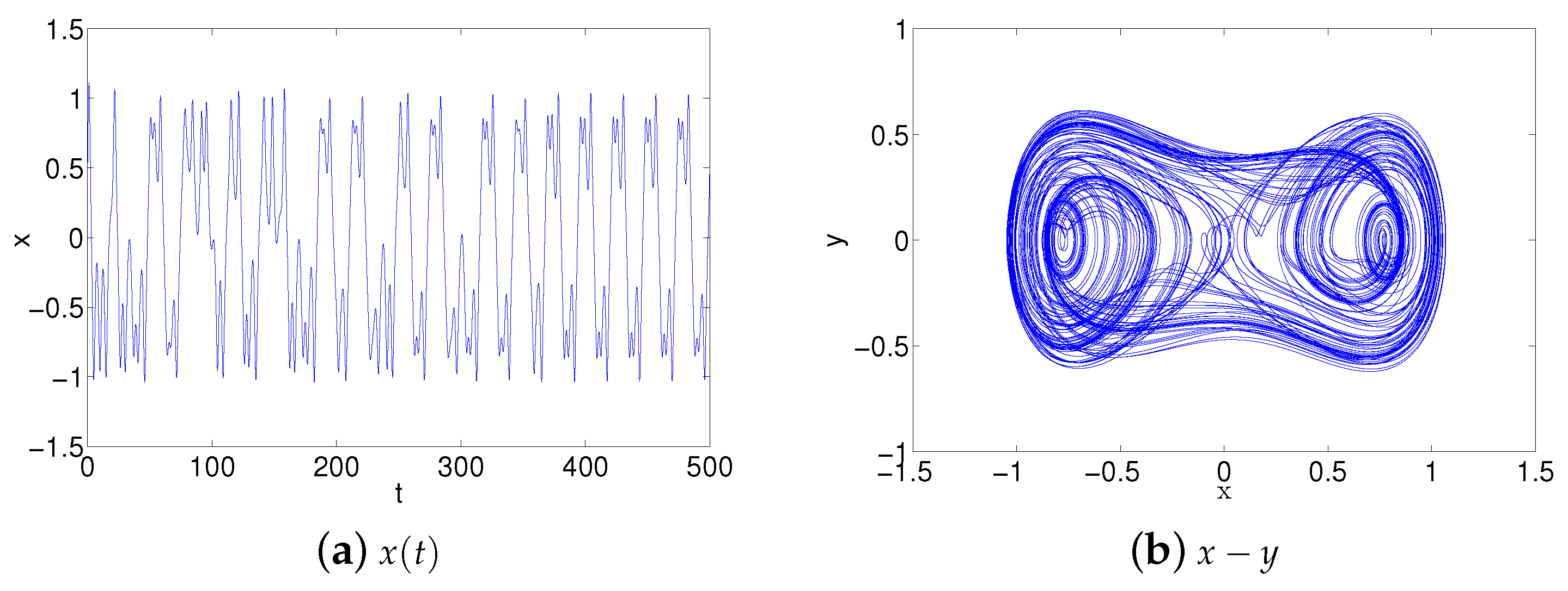
. Before autonomous Ikeda system implementing, the system defined by Equation (
1) is tested with a numerical simulation tool. The numerical simulation results of Ikeda system are illustrated in
Figure 3 by adopting the Fourth-Order Runge-Kutta Method in matlab. The maximum value of
was more than
according to simulation results, System (
1) is rescaled to
as following:
According to the Equation (
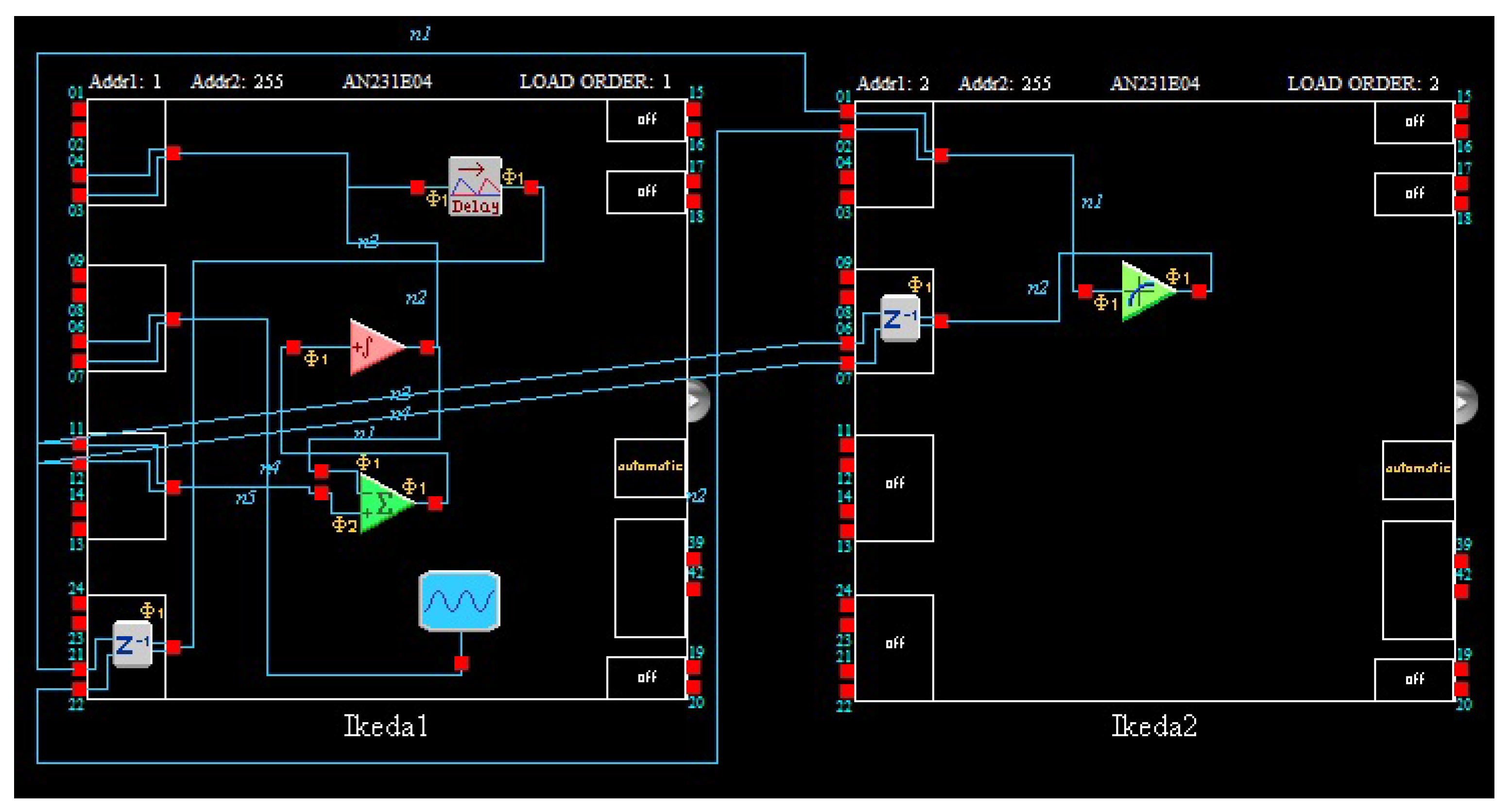
2), the circuit is constructed.
is implemented by a programmable transfer function module. We can design and realize all kinds of nonlinear functions by using the transfer function module. Compared with analog circuit design techniques, it is very easy, efficient and economical to help us realize all kinds of nonlinear systems. At the same time, the delay of circuit was designed by the delay module, so we can change the delay parameter easily by programming. Besides, attention should be paid to the time scale conversion when the analog circuit is constructed by the Equation (
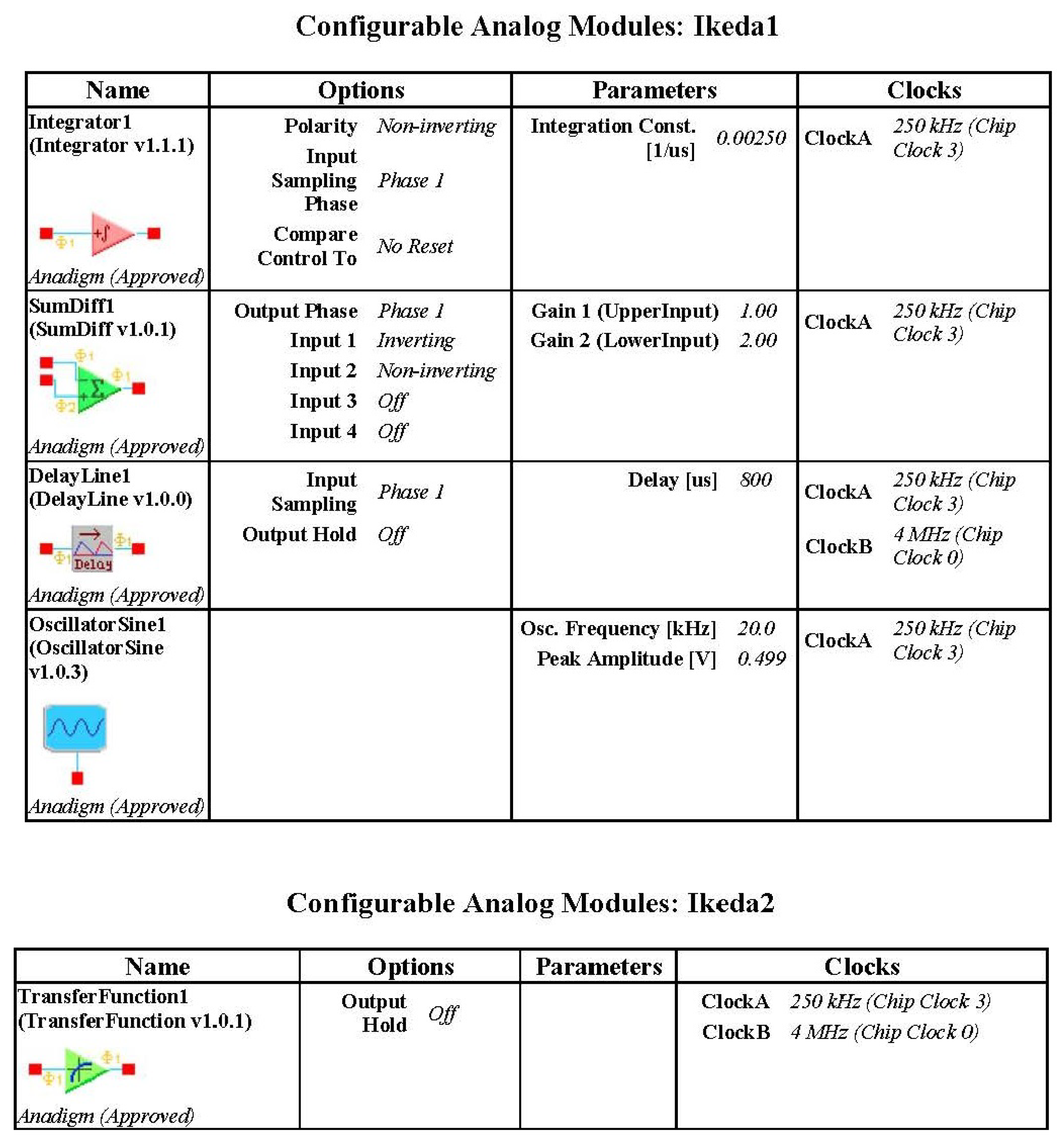
2). The delay time is 2 and the integral constant of integrator of FPAA is usually determined as 0.0025 1/us. Therefore, the parameters of the actual delay module are 800 us. The circuit diagram constructed by AD2 software is illustrated in
Figure 4.
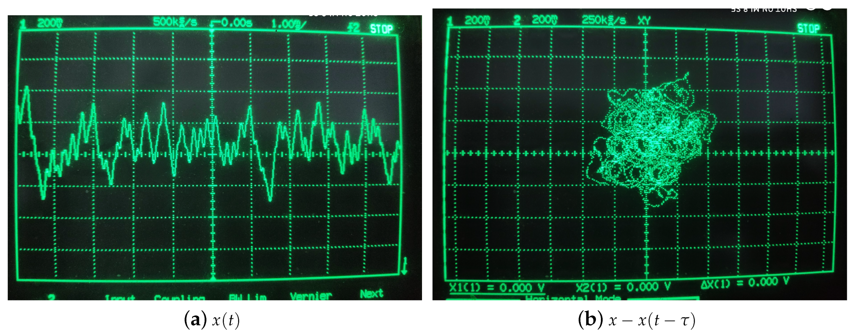
Because the chip resources of FPAA are limited, a chip cannot contain both transfer function module and delay module, it needs two FPAA chips to implement, system state-variable
x is output by IO1. The chaotic dynamics and the chaotic attractor have been showed in
Figure 5. The parameters are showed in
Figure 6.
Then we further analyze Shannon entropy and Lyapunov exponents of time series output by Ikeda circuit and simulation system. We sample 130,000 points to be used to test for the Ikeda circuit with a sample rate of 256 kHz, then, the number of point of Ikeda simulation system is also 130,000 and the step of simulation system is 0.01. The results are listed in the
Table 1.
Experimental results showed that Shannon entropy and Lyapunov exponents of Ikeda circuits and simulation system are approximately equal. Therefore an autonomous Ikeda chaotic system has been implemented successfully by using FPAA programmable device according to pictorial results and quantitative results.
3.2. Non-Autonomous Duffing System
Apart from the autonomous time-delay chaos system implemented by FPAA in the above section, FPAAs are also fit to implement non-autonomous time-delay chaos systems by programming and reconfiguring. In this section, we will introduce how a non-autonomous time-delay chaotic system can be implemented by using a FPAA device.
The Duffing system is one of the most typical and important objects in nonlinear dynamics, because it can model the large deformation or similar properties in an engineering structure. A lot of engineering systems could be described by Duffing or Duffing-based oscillators to enlighten their complicated dynamical behaviors and mechanisms. The time-delay equation of Duffing system is as follows according to this paper [
18].
In the above equation,
x denote the state variables of the system,
,
c and
k are system parameters and
represents delay time. These parameters are determined as
,
. This system is appropriate for programmable and reconfigurable design and implementation. The new designs are implemented more easily and inexpensively by changing system parameters of the Duffing system flexibly through software. FPAA device has an internal wave generator, it can generate many waves such as sin-waves and square waves, and the frequency, amplitude and other parameters of waves can be changed easily by programming. Therefore, it is non-essential to use an external AC source in FPAA implementation of the Duffing system and the amplitude and frequency parameters of the sin-wave can be easily adjusted by programming. As in the above Ikeda system, the necessary system simulation is required before FPAA modeling. The chaotic dynamics and the chaotic attractor of the simulation have been showed in
Figure 7. According to the simulation results the System (3) is rescaled to
as follows:
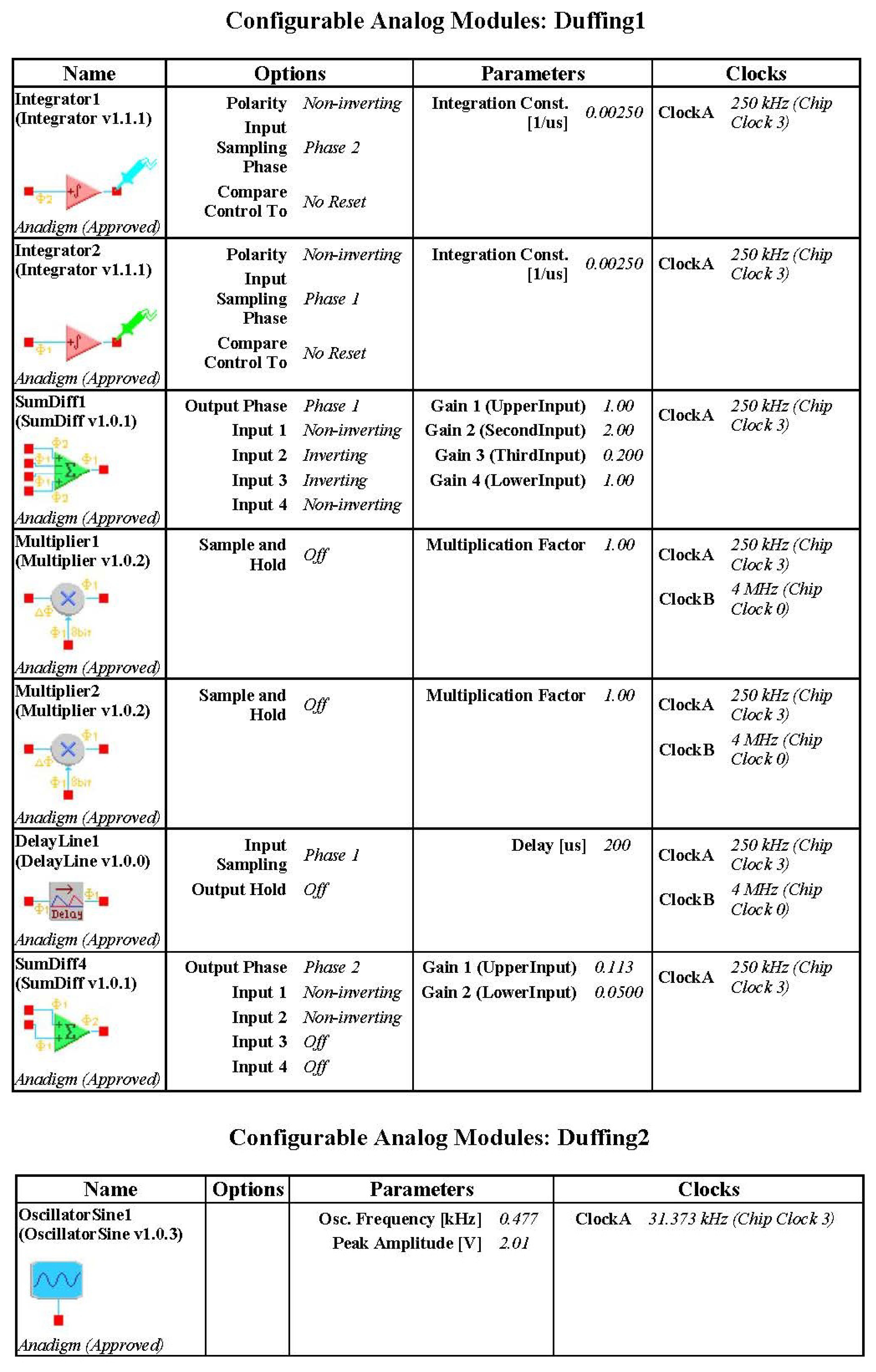
Then the Duffing system is modeled with an FPAA software tool. The Duffing system also needs an AC source module, which is different from autonomous time-delay chaos system. Attention should be paid to the time scale conversion when the analog circuit is constructed by the Equation (
4). The
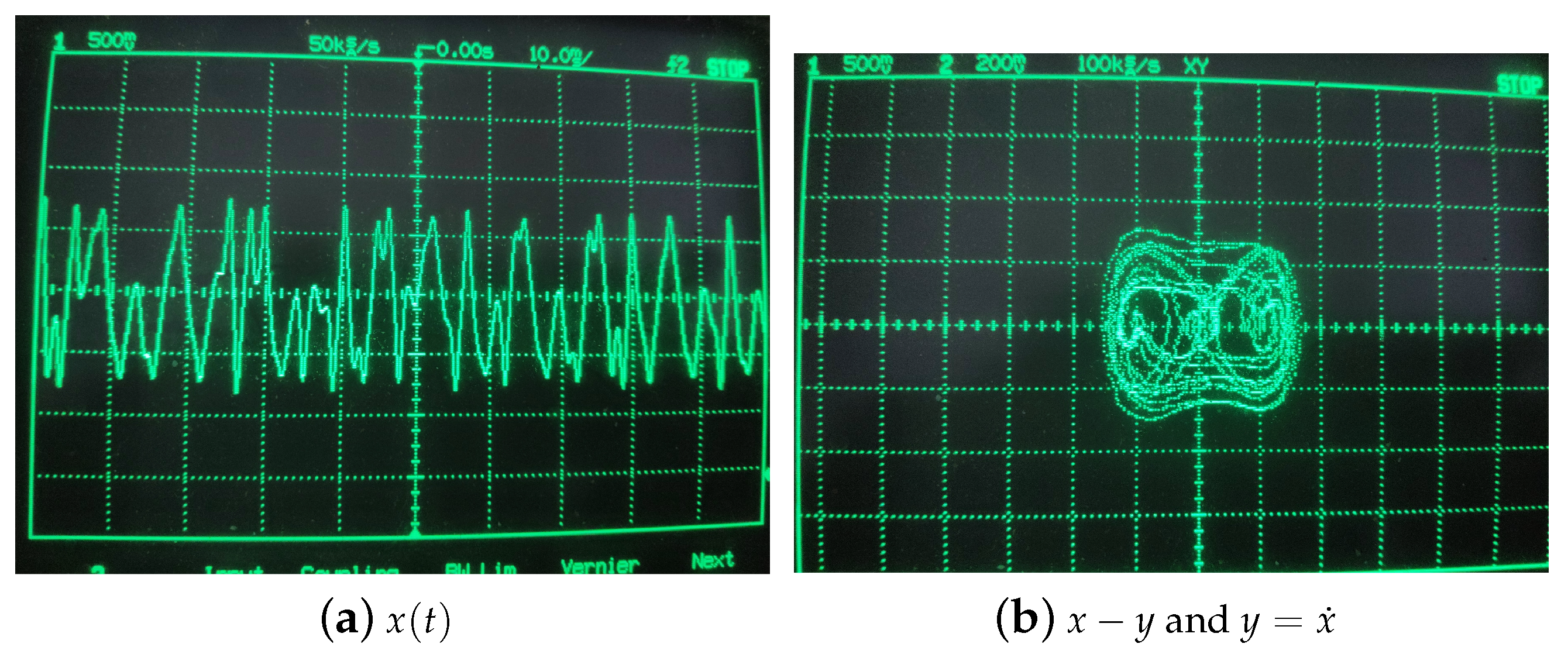
is 1.2 and the integral constant of integrator of FPAA is usually determined as 0.0025 1/us. Therefore, the frequency of the AC source block is 0.477 kHz. This model is downloaded to the FPAA development board via a serial port, and experimental measurements obtained from I/O connections of the FPAA board are illustrated in
Figure 8. The results of experiment have been showed in
Figure 9 and the circuit parameters are desplayed in
Figure 10. After that, we further analyze Shannon entropy and Lyapunov exponents of the time series output by a Duffing circuit and simulation system. Like the Ikeda system, we sample 130,000 points to be used to test for Duffing circuit and the sample rate is 256 kHz. The number of point of Duffing simulation system is 130,000 and the step of simulation system is 0.01. The results are listed in the
Table 2.
Experimental results showed that Shannon entropy and Lyapunov exponent of Duffing circuit and simulation system are approximately equal. Therefore non-autonomous duffing chaotic system has also been implemented successfully by using FPAA programmable device according to pictorial results and quantitative results.
4. Discussion
Here, we have designed and realized an autonomous time delay Ikeda circuit and non-autonomous time delay Duffing circuit successfully according to the analysis of phase picture, Shannon entropy and Lyapunov exponents. We download time delay chaos circuits pre-designed in software to the development board. After this, different chaos circuits can be implemented in the same development, which greatly reduces our design time. At the same time, the range of realizable chaos circuits based on FPAA is enlarged by constructing chaotic systems with time delay in this paper. This is conducive to researchers of chaos secure communication, because the time-delay chaotic source in chaotic secure communication can be realized by programming, and more importantly, the parameters of chaotic source can be changed easily by a programmable way. Although there are many advantages of FPAA in this paper, there are also limitations, at first, as some complex time-delay chaotic circuits may not be realized because the chip resources of FPAA are limited. Besides, the parameter range of the FPAA delay module is limited, and some time delay chaotic systems with large delay may not be realized. At last, the parameters of the delay used in the time-delay result in discrete delay. Therefore, the time-delay chaotic systems based on FPAA are finite dimension systems.
5. Conclusions
In this paper, we chose Ikeda and Duffing models as autonomous and non-autonomous design examples to introduce a universal programmable time-delay chaos system based on FPAA. Experimental results agree with the results obtained from simulation. It shows that this programmable design approach will be very useful in many applications based on time-delay chaotic systems. Many time-delay chaotic systems based on mathematical modeling will not need complex electronic hardware, and the design and implementation of time-delay chaotic systems will be more efficient, simpler and more economical. We hope that these design notes will be useful for researchers who wish to experimentally study time-delay chaotic systems.
Author Contributions
Conceptualization, H.-P.H., X.-H.L. and F.-L.X. Formal analysis, H.-P.H., X.-H.L. Software, X.-H.L.
Funding
This research was funded by National Key R & D Program of China (Grant No. 2017YFB0802000), Cryptography Theoretical Research of National Cryptography Development Fund (Grant No. MMJJ20170109).
Conflicts of Interest
The authors declare no conflict of interest.
References
- Mensour, B.; Longtin, A. Synchronization of delay-differential equations with application to private communication. Phys. Lett. A 1998, 244, 59–70. [Google Scholar] [CrossRef]
- Li, C.D.; Liao, X.F.; Wong, K.W. Chaotic lag synchronization of coupled time-delayed systems and its applications in secure communication. Phys. D-Nonlinear Phenom. 2005, 194, 187–202. [Google Scholar] [CrossRef]
- Cheng, M.F.; Gao, X.J.; Deng, L.; Liu, L.F.; Deng, Y.S.; Fu, S.N.; Zhang, M.M.; Liu, D.M. Time-Delay Concealment in a Three-Dimensional Electro-Optic Chaos System. IEEE Photonics Technol. Lett. 2015, 27, 1030–1033. [Google Scholar] [CrossRef]
- Robilliard, C.; Huntington, E.H.; Webb, J.G. Enhancing the security of delayed differential chaotic systems with programmable feedback. IEEE Trans. Circuits Syst. II-Express Briefs 2006, 53, 722–726. [Google Scholar] [CrossRef]
- Anadigm. Available online: www.anadigm.com (accessed on 12 March 2019).
- Liu, L.; Gao, Y.; Deng, J. Design and implementation of a reconfigurable mixed-signal SoC based on field programmable analog arrays. J. Semicond. 2017, 38, 115001. [Google Scholar] [CrossRef]
- Callegari, S.; Rovatti, R.; Sett, G. First direct implementation of a true random source on programmable hardware. Int. J. Circuit Theory Appl. 2005, 33, 1–16. [Google Scholar] [CrossRef]
- Natarajan, A.; Hasler, J. Fractional Hodgkin-Huxley Neuron and FPAA Dynamics. IEEE Trans. Biomed. Circuits Syst. 2018, 12, 918–926. [Google Scholar] [CrossRef] [PubMed]
- Natarajan, A.; Hasler, J. Modeling, simulation and implementation of circuit elements in an open-source tool set on the FPAA. Analog Integr. Circuits Signal Process. 2017, 91, 119–130. [Google Scholar] [CrossRef]
- Caponetto, R.; Caponetto, R.; Fortuna, L.; Frasca, M. Field programmable analog array to implement a programmable Chua’s circuit. Int. J. Bifurc. Chaos 2005, 15, 1829–1836. [Google Scholar] [CrossRef]
- Kilic, R.; Dalkiran, F.Y. Reconfigurable implementations of chua’s circuit. Int. J. Bifurc. Chaos 2009, 19, 1339–1350. [Google Scholar] [CrossRef]
- Kilic, R.; Dalkiran, F.Y. Programmable design and implementation of a chaotic system utilizing multiple nonlinear functions. Turk. J. Electr. Eng. Comput. Sci. 2010, 18, 647–655. [Google Scholar] [CrossRef]
- Kilic, R. Universal programmable chaos generator: Design and implementation issues. Int. J. Bifurc. Chaos 2010, 20, 419–435. [Google Scholar] [CrossRef]
- Dalkiran, F.Y.; Sprott, J.C. Simple Chaotic Hyperjerk System. Int. J. Bifurc. Chaos 2016, 26, 1650189. [Google Scholar] [CrossRef]
- Li, C.; Wesley, J.T.; Sprott, J.C.; Herbert, H.I.; Xu, Y. Constructing Infinitely Many Attractors in a Programmable Chaotic Circuit. IEEE Access 2018, 6, 29003–29012. [Google Scholar] [CrossRef]
- Li, C.; Wesley, J.T.; Sprott, J.C.; Zhang, R.; Lu, T. Linear synchronization and circuit implementation of chaotic system with complete amplitude control. Chin. Phys. B 2017, 26, 120501. [Google Scholar] [CrossRef]
- Lakshmanan, D.; Senthilkumar, D.V. Dynamics of Nonlinear Time-Delay Systems; Springer: Berlin, Germany, 2010; pp. 67–69. ISBN 978-3-642-14937-5. [Google Scholar]
- Shen, Y.; Wen, S.; Yang, S.; Guo, S.; Li, L. Analytical threshold for chaos in a Duffing oscillator with delayed feedbacks. Int. J. Non-Linear Mech. 2018, 98, 173–179. [Google Scholar] [CrossRef]
© 2019 by the authors. Licensee MDPI, Basel, Switzerland. This article is an open access article distributed under the terms and conditions of the Creative Commons Attribution (CC BY) license (http://creativecommons.org/licenses/by/4.0/).


