1. Introduction
In a Cloud Radio Access Network (C-RAN) architecture, a cloud unit, or baseband processing unit (BBU), carries out baseband signal processing on behalf of a number of radio units, or remote radio heads (RRHs), that are connected to the cloud through an interface referred to as fronthaul links [
1]. The C-RAN technology is recognized as one of the dominant architectural solutions for future wireless networks due to the promised reduction in capital and operational expenditures and the capability of large-scale interference management [
2]. A major challenge of C-RAN deployment is that high-rate baseband in-phase and quadrature (IQ) samples need to be carried on the fronthaul links of limited data rate. The design of signal processing strategies, including fronthaul compression techniques, for C-RAN was widely studied in the literature [
3,
4,
5,
6].
The mentioned works [
3,
4,
5,
6] and references therein assume a conventional fronthaul topology, whereby there are dedicated point-to-point fronthaul links from the cloud to each RRH as in Common Public Radio Interface (CPRI) specification [
7]. However, in modern implementations of C-RAN, as illustrated in
Figure 1, the fronthaul transport network will often be packet-based and it will have a multi-hop architecture built with general-purpose switches using network function virtualization (NFV) and software-defined networking (SDN) [
8,
9]. Packet-based fronthaul network can leverage the wide deployment of Ethernet infrastructure [
10].
Packet-based multi-hop networks are subject to congestion and packet losses. The traditional path diversity approach repeats the same packet on the multiple routes in order to mitigate these issues [
11,
12]. This approach can successfully reduce the packet loss probability at the cost of increasing the overhead in the fronthaul network. A limitation of these traditional schemes is that, when multiple packets arrive at the cloud within the tolerated delay, the signal quality utilized for channel decoding at the cloud is the same as if a single packet is received. To make a more efficient use of the multiple routes, in this paper, we propose a multiple description coding (MDC) scheme that operates directly on the baseband signals. Thanks to MDC, a better distortion level is obtained as more packets arrive at the cloud within the deadline. We refer to [
13] for an overview and for a discussion on applications of MDC. In addition, the work [
14] proposed the use of MDC to improve the achievable rate of a multicast cognitive interference channel.
Since, thanks to MDC, the signal quality varies depending on the number of packets arriving at the cloud, we propose that user equipments (UEs) leverage the broadcast approach in order to enable the adaptation of the transmission rate to the effective received signal-to-noise ratio (SNR) [
15,
16]. The broadcast approach defines a variable-to-fixed channel code [
17] that enables the achievable rate to adapt to the channel state when the latter is known only at the receiving end. The broadcast approach splits the message of each UE into multiple submessages that are encoded independently, and transmitted as a superposition of the encoded signals. With the proposed MDC-based solution, based on the packets received within a given deadline, the cloud performs successive interference cancellation (SIC) decoding of the UEs’ submessages with a given order so that the achievable rate can be adapted to the number of delivered packets. Therefore, the number of received packets determines the quality of the channel state known only at the receiver. Related methods were introduced in [
18] and [
19], where broadcast coding with layered compression [
20] was applied to the uplink of C-RAN systems with distributed channel state information [
18] and with uncertain fronthaul capacity [
19].
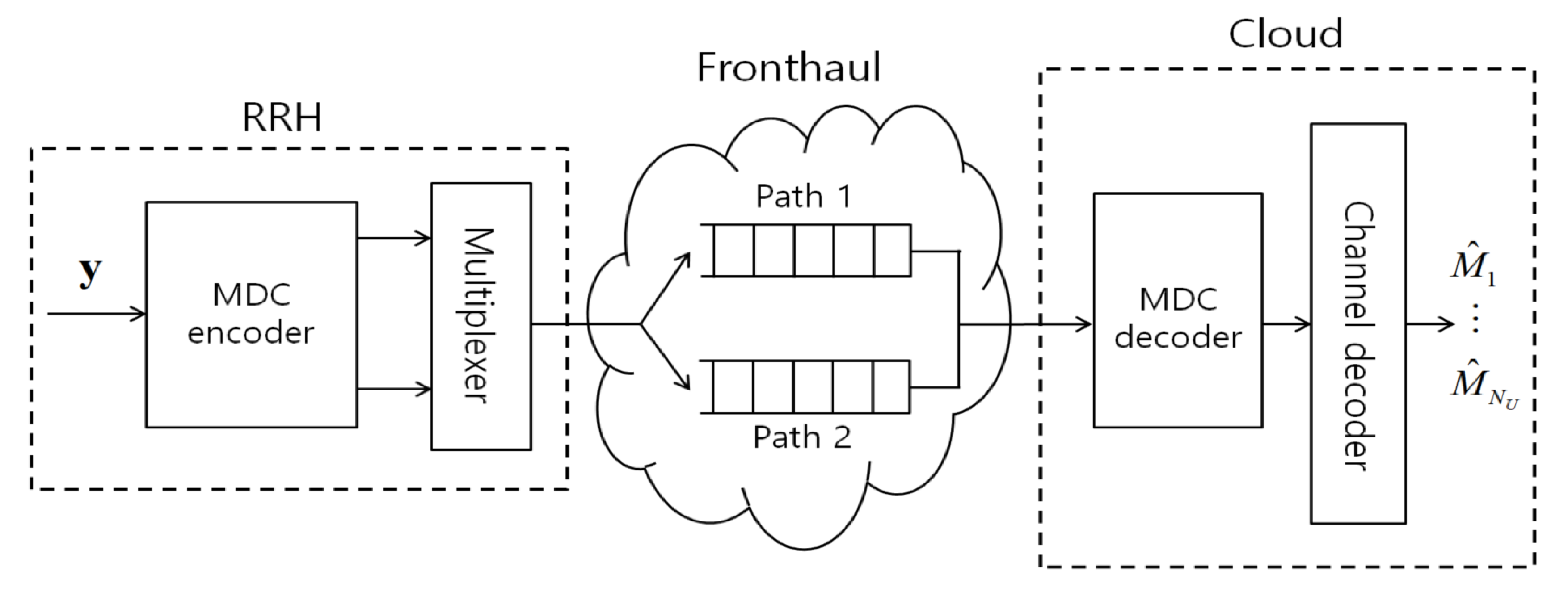
More specifically, in this work, we study joint radio and fronthaul transmission for the uplink of a C-RAN with a packet-based fronthaul network. In the system, the uplink received baseband signal of each RRH is quantized and compressed producing a bit stream. The output bits are then packetized and transmitted on the fronthaul network. Following a standard approach to increase robustness to network losses and random delays (see, e.g., [
11,
12]), we assume that the packets are sent over multiple paths towards the cloud as seen in
Figure 2. This can be done by using either conventional packet-based duplication [
11,
12] or the proposed MDC approach. The packets may be lost due to network delays or congestion when they are not received within a tolerable fronthaul delay dependent on the application. Based on the packets that have arrived within the delay, the cloud carries out decompression and channel decoding.
The rest of the paper is organized as follows. In
Section 2, we describe the system model for the uplink of a C-RAN with packet-based fronthaul network. In
Section 3, we present the proposed MDC scheme which operates in a combination with the broadcast coding. The optimization of the proposed scheme is discussed in
Section 4, and the advantages of the proposed scheme are validated with extensive numerical results in
Section 5. We discuss extension to general cases in
Section 6, and the paper is concluded in
Section 7.
We summarize some notations used throughout the paper as follows. The mutual information between random variables X and Y conditioned on Z is denoted as , and denotes the differential entropy of X. We define as the circularly symmetric complex Gaussian distribution with mean and covariance . The expectation, trace, determinant and Hermitian transpose operations are denoted by , , and , respectively, and represents the set of all complex matrices. We denote as an identity matrix of size N, and ⊗ represents the Kronecker product. indicates that the matrix is positive semidefinite.
3. Robust Compression Based on Multiple Description Coding
In this section, we propose a robust compression technique based on MDC, which, in combination with broadcast coding, enables the achievable rate to be adapted to the number of packets collected by the cloud, and hence to the current network congestion level. To highlight the idea, we assume that the RRH has available two paths to the cloud. Extensions will be discussed in
Section 6. The traditional path diversity approach repeats the same packet on the two routes [
11]. More sophisticated forms of packet-based encoding, such as erasure coding studied in [
12], are not applicable to the case of two paths. Accordingly, if one or two packets are received by the fronthaul deadline of
slots, the signal is decompressed and decoding is carried out at the cloud. Note that, if both packets are received, the signal quality is the same as if one packet is received. In contrast, we propose to adopt MDC as seen in
Figure 2. With MDC, if one packet is received by the deadline
, we obtain a certain distortion level, while we obtain a better distortion level if both packets are received ([
21] Ch. 14).
In the MDC approach, the RRH first quantizes and compresses the received signal to produce quantized signals , and . Packets and are sent on two separate paths to the cloud, with sent on route l. By the properties of MDC, if only a single packet arrives at the cloud within deadline , the MDC decoder can recover the quantized signal , while the signal can be recovered if the both packets are received in time.
Denote as
the number of bits per symbol used to represent the signal for each of the quantized packets
and
. We refer to
as the compression output rate. As shown in ([
21] Ch. 14), the rate
should satisfy the conditions
To evaluate (
2)–(
4), as in, e.g., [
3,
4,
5,
6], we assume standard Gaussian quantization codebooks, so that the quantized signals can be modeled as
for
, where the quantization noise
is independent of the signal
and distributed as
for
and
. The right-hand sides (RHSs) of (
2)–(
4) can hence be written as
where we have defined the notations
and
with
denoting a column vector of all ones.
We now discuss the derivation of the probability that a packet
l is delivered to the cloud within the given deadline
. The number
of fronthaul packets that need to be delivered within the time
to the cloud for the
lth description is given as
since
is the number of bits per description and
is the number of available bits per frame. Note that
increases with the compression output rate
and decreases with the size of the fronthaul packet
. Then, the probability that description
sent on route
l is received at the cloud within the deadline
is given as
where
are independent and geometrically distributed random variables with parameter
such that the sum
is a negative binomial random variable with parameters
and
([
22] Ch. 3). Therefore, the probability (
9) can be written as
where
is the regularized incomplete beta function defined as
with
. For simplicity of notation, we also define the probabilities
and
that no or both descriptions arrive at the cloud within the deadline.
Define as
the number of descriptions that arrive at the cloud within the given deadline
. The probability distribution
can then be written as
with the notation
and
.
Broadcast Coding
With MDC, the quality of the information available at the cloud for decoding the transmitted signals
is determined by the number
M of descriptions that arrive at the cloud. Since the state
is not known to the UEs, the rate cannot be a priori adapted by the UEs depending on the congestion level. To handle this issue, we propose that each UE
k adopts a broadcast coding strategy [
15,
16,
17,
18] as
where the signals
and
encode independent messages of UE
k, and the decoder at the cloud is required to reliably recover only the signals
with
when
descriptions arrive at the cloud. We denote the rate of the signal
as
for
and
. We make the standard assumption that the
jth signal
of each UE
k is distributed as
, where the powers
need to satisfy the power constraint
. Under the described assumption, the covariance matrix
of all the transmitted signals
is given as
with
.
The signal
collected at the cloud when
descriptions have arrived at the cloud is given as
For the case of
, the cloud receives
or
. In (
14), we set
without loss of generality, since
and
are statistically equivalent.
When no description arrives at the cloud (i.e.,
), the cloud has no information received from the RRH, and none of the signals
can be decoded by the cloud. When only a single description arrives at the cloud (
), the cloud jointly decodes the first-layer signals
based on the received quantized signal
. Therefore, the achievable sum-rate
of the first-layer signals is given as
where we have defined the vector
that stacks the layer-
m signals of all the UEs, and the notations
and
.
If both descriptions arrive at the cloud (i.e.,
), the cloud first jointly decodes the first-layer signals
from the recovered quantized signal
, and cancels the impact of the decoded signals from
, i.e.,
. Then, the cloud decodes the second-layer signals
based on
. Thus, the achievable sum-rate
of the second-layer signals is given as
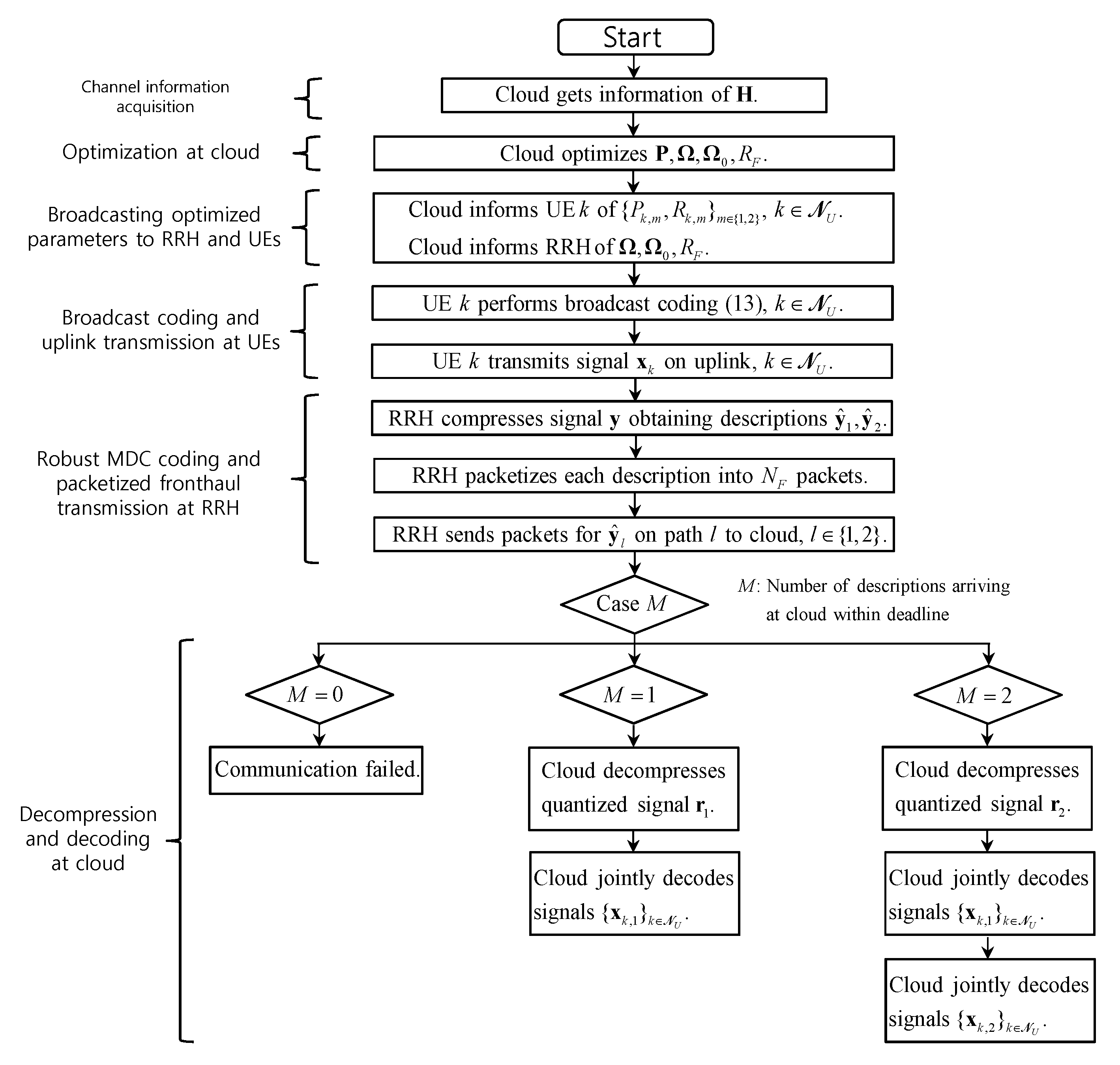
In summary, the whole system operates as follows. The cloud first obtains the channel state information and optimizes the variables related to broadcast coding and MDC coding. The optimization will be discussed in
Section 4. After the optimization algorithm is finished, the cloud informs the UEs and the RRH of the optimized variables. The UEs perform broadcast coding and uplink transmission, and the RRH compresses the received signal obtaining two descriptions which are packetized and sent on fronthaul paths to the cloud. Based on the received packets, the cloud performs MDC decoding of the quantized signals and SIC decoding of the UEs’ messages. We provide a flowchart that illustrates the described operations of the proposed system in
Figure 4.
4. Problem Definition and Optimization
For fixed instantaneous channel states
, we aim at jointly optimizing the compression output rate
, the power allocation variables
and the quantization noise covariance matrices
with the goal of maximizing the expected sum-rate denoted as
. Here the expectation is taken with respect to the random variables
with
, which depend on the current congestion level of the packet network. The expected sum-rate
is hence given as
with the notations
and
. The expected sum-rate
can be expressed as a function of
,
and
:
We note that increasing the compression output rate
has conflicting effects on the expected sum-rate
. On the one hand, the probability of timely reception of all fronthaul packets decreases with
due to the increased number
of packets in (
8). On the other hand, once the packets have arrived at the cloud, a better sum-rate can be achieved with larger
, since the quantization noise signals have smaller powers.
The problem mentioned above can be stated as
To tackle the problem (19), we first note that, if we fix the compression output rate variable
, the problem becomes a difference-of-convex (DC) problem as in [
23]. Therefore, we can find an efficient solution by adopting the concave convex procedure (CCCP) approach (see, e.g., [
24,
25]). The detailed algorithm that tackles (19) with the CCCP approach is described in Algorithm 1, where we have defined the functions
,
and
as
with the function
defined as
| Algorithm 1 CCCP algorithm for problem (19) for fixed |
1. Initialize the variables , to arbitrary matrices that satisfy the constraints (19b), (19c) and (19d), and set .
2. Update the variables as a solution of the convex problem:
3. Stop if a convergence criterion is satisfied. Otherwise, set and go back to Step 2. |
We have discussed the optimization of the power allocation variables
and the quantization noise covariance matrices
for fixed compression output rate
. For the optimization of
, we propose to perform a 1-dimensional discrete search over
with
and
. Here we have excluded the values
with non-integer
from the search space
. This does not cause a loss of optimality, since we can increase the compression output rate, hence improving the compression fidelity to
without increasing the number
of packets in (
8) that needs to be delivered to the cloud.
Optimization of Traditional Path-Diversity Scheme
In this subsection, we discuss the optimization of the traditional path-diversity (PD) scheme, in which the RRH repeats to send the same packet on the available two routes [
11]. Accordingly, the RRH produces only a single quantized signal
, where the quantization noise
is independent of
and distributed as
under the assumption of standard Gaussian quantization codebooks. Denoting as
the compression output rate for the quantized signal
, the rate
should satisfy the condition
To evaluate the achievable sum-rate, we define the binary variable
, which takes 1 if at least one packet arrives at the cloud, and 0 otherwise. The probability distribution of
D can be written as
If both packets sent on two routes are lost (i.e.,
), the cloud cannot decode the signals sent by the UEs. If the cloud receives at least one packet (
), the cloud can perform decoding of the signals
based on the received quantized signal
, and the achievable sum-rate can be written as
The expected sum-rate
can be expressed as
The problem of maximizing the expected sum-rate
with the traditional PD scheme can hence be stated as
We can tackle the problem (25) in a similar approach to that proposed for addressing (19).
5. Numerical Results
In this section, we provide numerical results that validate the advantages of the proposed robust baseband compression technique based on MDC coding scheme. We consider a system bandwidth of 100 MHz and assume that each wireless frame consists of
channel uses. We also assume that each fronthaul packet has
bits (i.e., 750 bytes) which corresponds to a half of the maximum payload size per frame defined in Ethernet [
10]. Denoting as
the fronthaul capacity in bit/s, each fronthaul packet has the duration of
. If we define the maximum tolerable delay on fronthaul network as
s, the deadline
in packet duration is given as
. In the simulation, we set
ms. For simplicity, we assume that all paths have the same error probability
for all
. Regarding the channel statistics, we assume that the positions of the UEs and the RRH are uniformly distributed within a circular area of radius 100 m. The elements of the channel matrix
are independent and identically distributed (i.i.d.) as
. Here the path-loss
is modeled as
, where
represents the distance between the RRH and UE
k, and
is the reference distance set to
m. We set the noise covariance to
, and the SNR is defined as
.
5.1. Fixed Compression Output Rate
We first evaluate the expected sum-rate performance
when only the power allocation variables
and the quantization noise covariance matrices
are optimized according to Algorithm 1 for fixed compression output rate
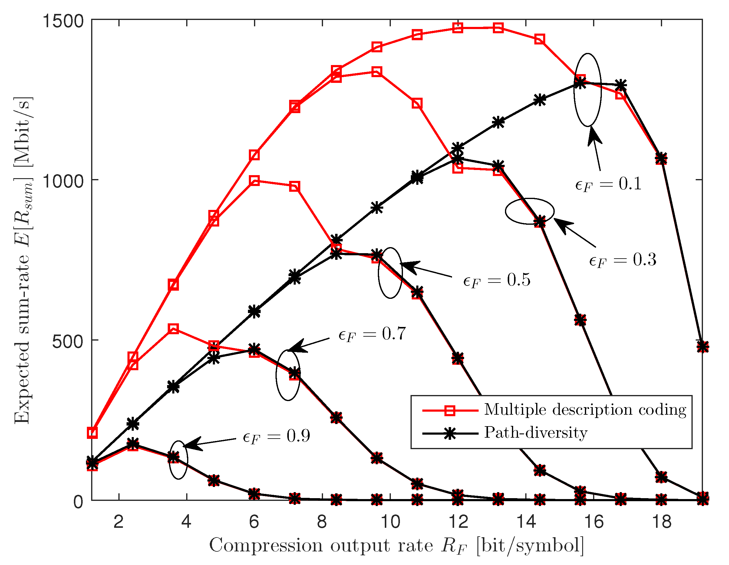
. In
Figure 5, we plot the expected sum-rate
versus the compression output rate
for various values of path error probability
with
,
,
,
Mbit/s and 25 dB SNR. We observe that, for both the MDC and PD schemes, the optimal compression output rate
increases as the fronthaul error probability
decreases. This suggests that, with smaller
, the packet networks become more reliable and hence more packets can be reliably delivered to the cloud within the deadline. Furthermore, the figure shows that, with MDC, it is optimal to choose a lower compression output rate with respect to PD. This is because, as the fronthaul quality improves in terms of the error probability
, the PD scheme can only increase the sum-rate by increasing the quality, or the compression output rate
, of each individual description, since it cannot benefit from reception of both descriptions. In contrast, the MDC scheme can operate at a lower
, since the quality of the compressed signal is improved by reception of both descriptions. Receiving both descriptions tends to be more likely if the compression output rate is lower and hence the number of fronthaul packets per frame is reduced.
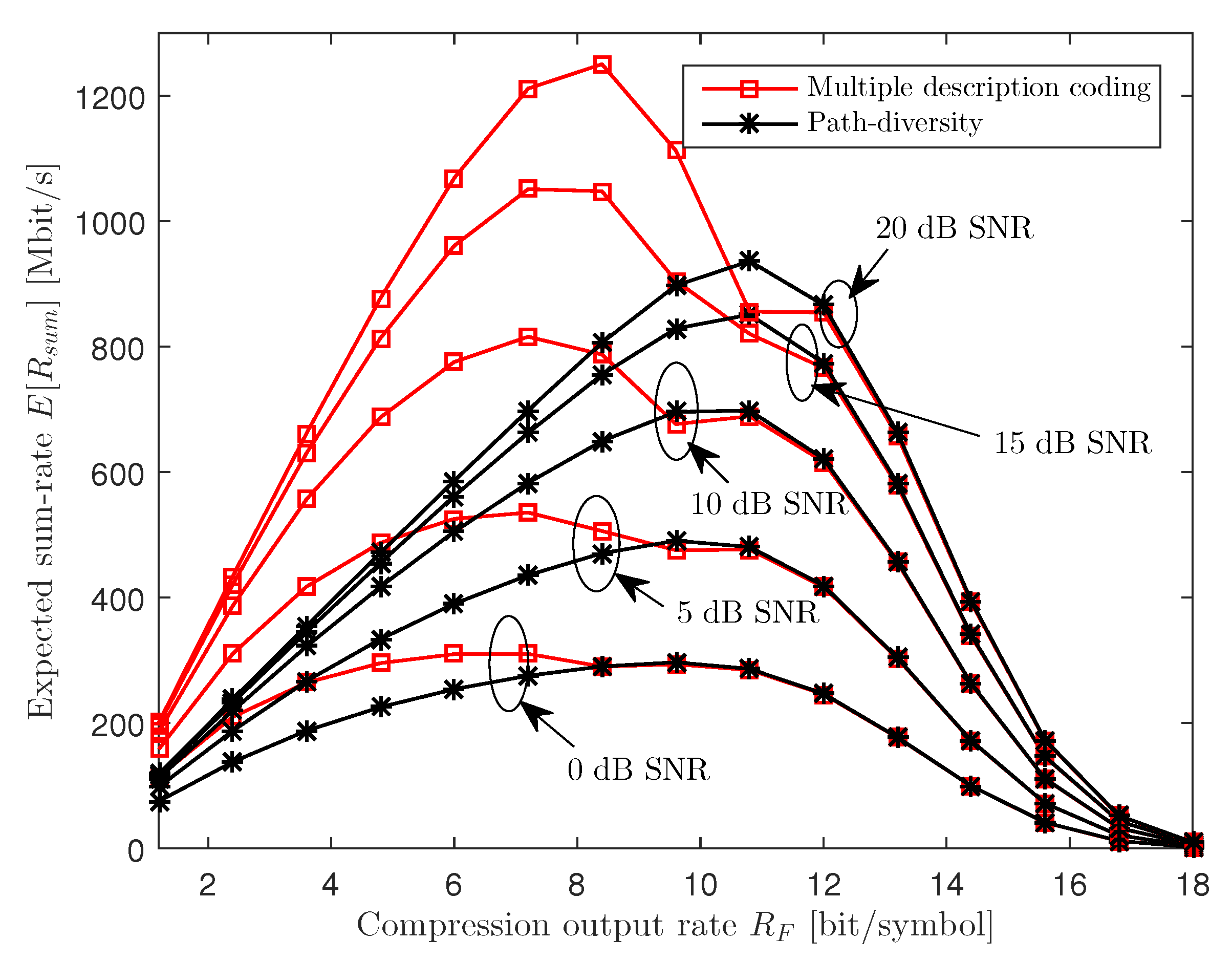
In
Figure 6, we depict the expected sum-rate
versus the compression output rate
for various SNR levels with
,
,
,
and
Mbit/s. The figure shows that, as the SNR increases, the optimal compression output rate
slightly increases for both MDC and PD. This is because, while the SNR level does not affect the reliability of the packet fronthaul network, it is desirable for the RRH to report better descriptions of the uplink received signals to the cloud when the received signals carry more information on the UEs’ messages.
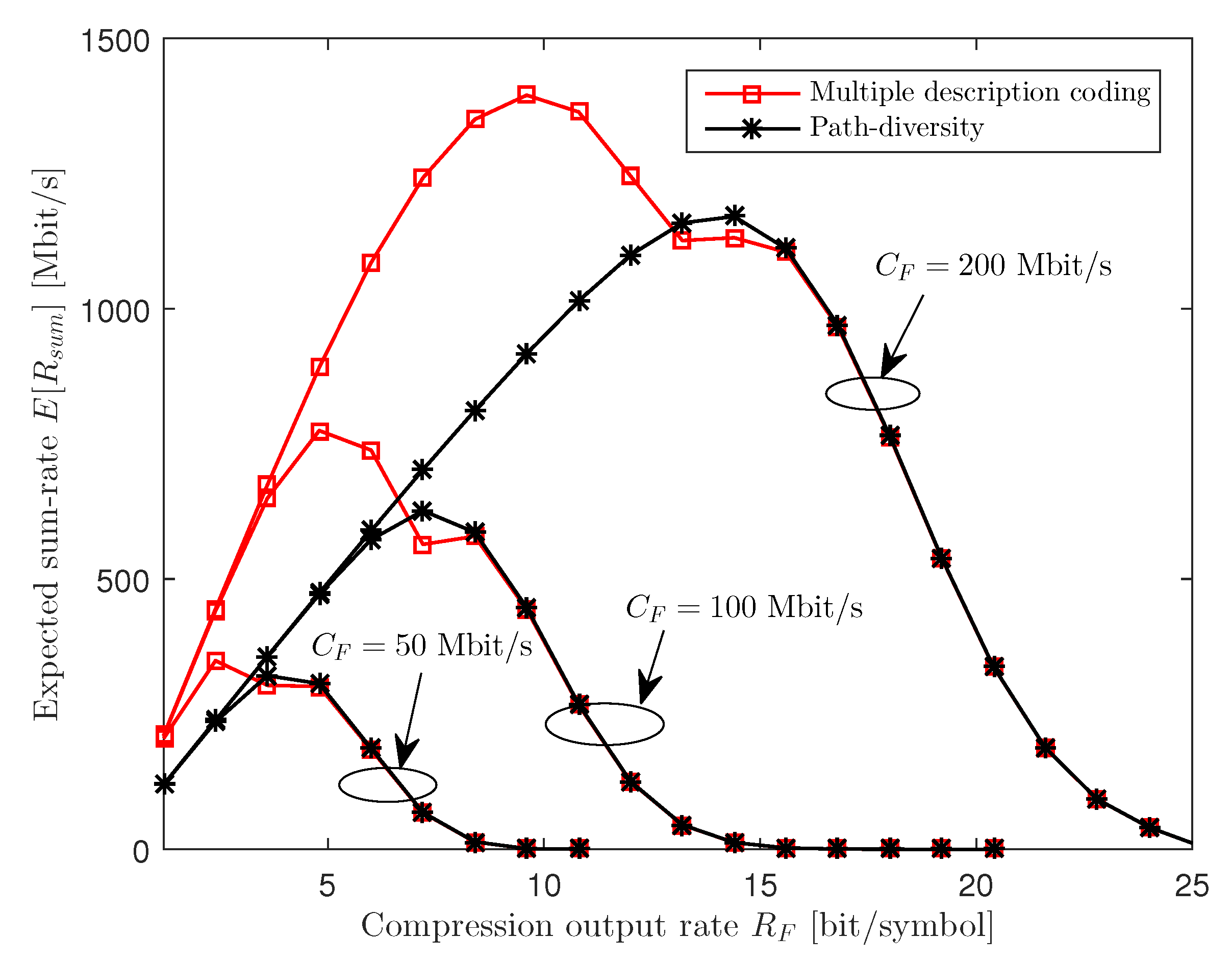
Figure 7 plots the expected sum-rate
with respect to the compression output rate
for various fronthaul capacity
with
,
,
,
and 25 dB SNR. Since more packets, and hence more bits, can be transferred to the cloud within the deadline
with increased fronthaul capacity
, the optimal compression output rate
grows with
for both the MDC and PD schemes.
5.2. Optimized Compression Output Rate
In this subsection, we present the expected sum-rate
achieved when the power allocation variables
, the quantization noise covariance matrices
and the compression output rate
are jointly optimized as discussed in
Section 4. In
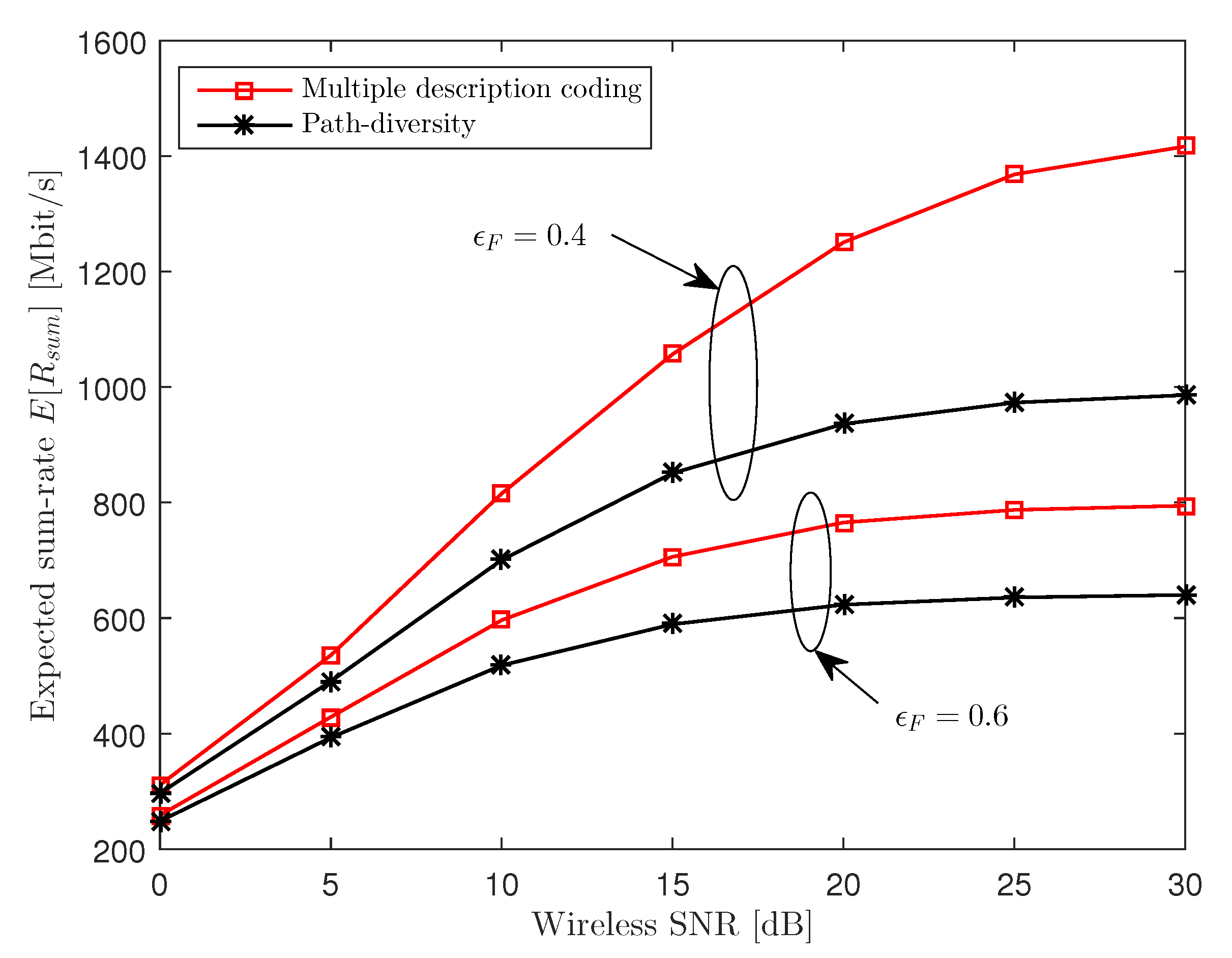
Figure 8, we plot the expected sum-rate
versus the SNR for
,
,
,
and
Mbit/s. We observe from the figure that the MDC scheme shows a larger gain at a higher SNR level. This suggests that, as the SNR increases, the overall performance becomes limited by the quantization distortion which is smaller for the MDC scheme than for PD.
In
Figure 9, we plot the expected sum-rate
versus the fronthaul capacity
for
,
,
,
and 25 dB SNR. The figure illustrates that the MDC scheme shows relevant gains over the PD scheme in the intermediate regime of
. This is because, when the fronthaul capacity
is sufficiently large, the whole system has a performance bottleneck in the wireless uplink rather than in the fronthaul network, and the sum-rate converges to 0 as
approaches 0.
6. Extension to General Numbers of RRHs and Fronthaul Paths
In this section, we briefly discuss the application of MDC to the case of general number
of RRHs and
fronthaul paths. Each RRH
i sends
descriptions
,
, one on each of the routes to the cloud, where
is a quantized version of the received signal
defined as
As in (
5), under Gaussian quantization codebook, the quantization noise
is independent of
and is distributed as
. With MDC, the cloud can recover the signal
if only the packets for the
lth description
arrive at the cloud within the deadline. If a subset of descriptions from RRH
i arrive in time, the cloud can obtain a better signal from RRH
i, whose quality increases with the size of the subset. Generalizing (
2)–(
4), conditions relating the resulting quantization noise covariance matrices and the output compression rate
can be found in [
26].
We define as
the number of descriptions of RRH
i that arrive at the cloud within the deadline
. The probability distribution
of
is then given as
where
is an indicator function that outputs 1 if the input statement is true and 0 otherwise; and the probability
is defined as
.
As discussed, with MDC, the quality of the information available at the cloud depends on the numbers of descriptions that arrive at the cloud. This means that there are distinct states depending on the current congestion level of the packet network. In principle, the broadcast coding can be applied in such a way that each UE k sends a superposition of layers. However, this approach does not scale well with respect to , and it is not straightforward to rank all the states.
To adopt a broadcast coding strategy with a scalable complexity, a possible option is to fix the number of layers, denoted as
L, as in, e.g., [
27]. Accordingly, the transmit signal
of each UE
k is given by a superposition of
L independent signals
,
, i.e.,
with the power constraint
. We then partition the
congestion states into
L groups, denoted as
, so that the layer-
l signals
can be decoded by the cloud for all congestion states in
with
. Since we can evaluate the probability of all the states using (27), the expected sum-rate can be expressed as a function of the compression output rate, the power allocation variables and the quantization covariance matrices. Therefore, we can tackle the problem of jointly optimizing these variables in a similar approach to that proposed in
Section 4. We leave the evaluation of the impacts of the numbers of RRHs
and fronthaul paths
to future work.

.png)