1. Introduction
The power generation sector is one of the most expanding sectors in the Gulf countries mainly due to the rise of the population size, economic and industrial development and the availability of fossil fuels. Several new projects are planned, commissioned or already launched. The power plants are composed mainly of gas turbine units, steam turbines and combined cycle plants. Several questions are arising including the optimum operation of these power plants, the reduction of their energy consumption and the reduction of their environmental impacts. The possible electrical interconnection between the Gulf countries is another important issue.
The Gulf Cooperation Council (GCC) was formed in 1981, consisting of the six Arab Gulf countries, namely the United Arab Emirates, Bahrain, Saudi Arabia, Oman, Qatar and Kuwait [
1]. Based on some previous studies, it has been demonstrated that the electrical interconnection among the GCC countries is possible technically and economically. As a result, the GCC Interconnection Authority (GCCIA) was established in July 2001 with headquarters located in Dammam and the control center in Ghunan, Saudi Arabia [
1,
2,
3].
Table 1 presents the electrical capacity of interconnection of each country in GCC. Saudi Arabia contributes with its eastern region having the largest production of electricity in the Kingdom [
4].
Gas turbine plants are widely used to generate electricity worldwide, in particular to cover the peak load demand as in Kuwait [
5] and to produce electrical power in inland regions, such as in Saudi Arabia. For instance, gas turbine units produced about 50% of the total electrical capacity of the Saudi Kingdom in 2012 [
6].
Gas turbines are considered constant volumetric flow rate machines using ambient air as the working fluid [
7,
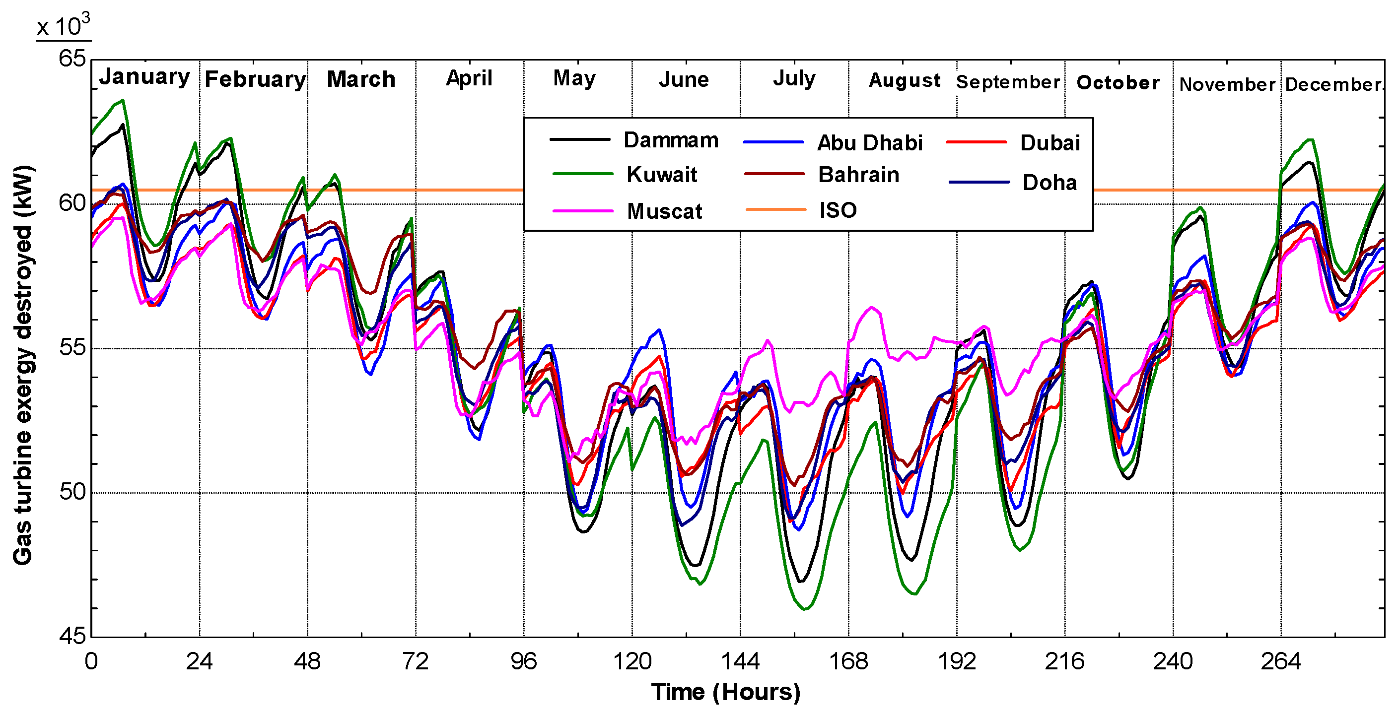
8]. Therefore, ambient conditions (temperature, humidity and pressure) are considered as important factors affecting the performance of such power plants. The production capacity of gas turbines is rated by the International Standards Organization (ISO), which specified the following reference air inlet conditions: air temperature 15 °C (59 °F), relative humidity 60% and absolute pressure (sea-level) 101.325 kPa (14.7 psia).
Several studies have discussed the effect of ambient conditions on the performance of gas turbines. Al Ibrahim et al. [
9] tested a simple gas cycle in the central Qaseem region of Saudi Arabia. They concluded that high ambient temperatures of mid-day of the summer season cause a 24% decreasing in system capacity [
10]. Baakeem et al. [
11] studied theoretically the effect of the average hourly temperature and relative humidity on the performance of a typical gas turbine unit used in three Saudi regions: Ad Dammam, Riyadh and Jeddah. The obtained results showed that both ambient temperature and humidity have a significant effect on the gas turbine performance. They reported that due to weather variation, the maximum electricity production losses were 20%, 18% and 17.5% of ISO production in Riyadh, Ad Dammam and Jeddah, respectively. De Sa and Al Zubaidy [
12] investigated the gas turbine performance at varying ambient temperatures for specific turbines (SIEMENS SGT 94.2 and SIEMENS SGT 94.3) installed at the Dewa Power Station located at Al Aweer, Phases II and III in Dubai, UAE. Each of these types of gas turbine has a power generation capacity of 160 MW and 265 MW, respectively. De Sa and Al Zubaidy [
12] reported that for every 1 °C rise in ambient temperature above ISO conditions, the units lose 0.1% in terms of thermal efficiency and 1.47 MW of its gross (useful) power output. Al-Fahed et al. [
8] focused on the effect of ambient air temperature and relative humidity on the performance of a gas turbine cogeneration system under Kuwait summer climate conditions. They concluded that increasing inlet air temperatures have a negative effect on the net power and thermal efficiency of the gas turbine, while increasing relative humidity has a small positive impact on gas turbine cycle net power and thermal efficiency. For an integrated gas turbine and heat recovery steam generator (HRSG), increasing inlet air temperature has a negative impact on the power to heat ratio (PHR), while relative humidity has no effect on PHR. Ameri and Hejazi [
13] reported that there are more than 170 gas turbine units in Iran with a combined capacity of 9500 MW. In the summer season, the power output of those units is about 80% of their rated capacity, meaning that around 1900 MW are lost during the hot season. Erdem and Sevilgen [
14] analyzed the effect of ambient temperature on electricity production and fuel consumption of two simple gas turbine models. They considered seven climate regions in Turkey using average monthly temperature data corresponding to those regions. They reported that electricity production loss occurs in all regions when the temperature is above 15 °C, and loss rates vary between 1.67% and 7.22% depending on the regions. Electricity generation increases by 0.27% to 10.28% when inlet air is cooled to 10 °C.
The second law of thermodynamics has been frequently used to analyze the performance of such power systems. Ameri et al. [
15] evaluated the irreversibility rates occurring in each component of Neka combined cycle power plants using exergy analysis. Khaliq [
16] analyzed the performance of a tri-generation system using energy and exergy balances, while Sanjay and Prasad [
17] evaluated the energy and exergy efficiencies of an inter-cooled combustion turbine-based combined cycle (ICCT-CC) power plant. Chen et al. [
18] investigated the exergy and energy levels of a combined cooling, heating and power system driven by a small-scale gas turbine at off design conditions. The performance of a gas turbine with air bottoming cycle (ABC) was investigated by Ghazikhani et al. [
19] using the first and second laws. Working fluid was treated as an ideal gas with variable specific heat, and the fuel was assumed to be pure methane. All components of the system were assumed to operate under adiabatic conditions and with fixed turbine and compressor isentropic efficiencies.
Bhargava et al. [
20] conducted thermo-economic analyses of various power augmentation technologies, implemented on a selected gas turbine using selected climatic conditions in order to identify the best techno-economic solution for the considered weather data. Bhargava et al. [
21] investigated the gas turbine performance enhancement approaches using wet cycles and hybrid cycles. These high performance cycles consist of modified Brayton cycles with humidification or water/steam injection and with fuel cells. They include an intercooled steam-injected gas turbine cycle, a humidified air turbine cycle, a cascaded humidified advanced turbine cycle, a Brayton cycle with high temperature fuel cells and their combinations with the modified Brayton cycles. The main results of this work show that the cycle efficiency obtained with those high performance systems can be comparable or better than combined cycle efficiency.
In hot climates, the performance of gas turbines can be enhanced by reducing air temperature at the compressor inlet, because cooled air has higher density, giving the turbine a higher mass flow rate and a lower power required by the compressor. Several cooling methods commonly called turbine inlet-air cooling technologies (TIAC) have been proposed and implemented. A good number of works have investigated the effect of inlet air-cooling systems (TIAC) on the performance of gas turbines and combined cycles [
7,
10,
22,
23,
24,
25,
26,
27]. Al-Ibrahim and Varnham [
10] conducted a review on inlet air-cooling technologies for enhancing the performance of combustion turbines in Saudi Arabia. Al-Ansary et al. [
7] studied the effect of inlet air cooling systems in gas turbines in Riyadh for every hour of every day during the period from May to September using four technologies. The authors have investigated the prospects of using a hybrid turbine inlet air cooling (TIAC) system consisting of mechanical chilling followed by evaporative cooling. Alhazmy et al. [
22] studied the effect of inlet air-cooling on gas turbine power output and efficiency using two different cooling techniques, namely direct mechanical refrigeration and evaporative water spray cooler, under the hot humid conditions of Jeddah, Saudi Arabia. Popli et al. [
23] enhanced the gas turbine efficiency by using 17 MW of gas turbine exhaust heat to provide 12.3 MW of cooling to cool compressor inlet air to 10 °C by single-effect water-lithium bromide (H
2O-LiBr) absorption chillers in the United Arab Emirates. The power requirements of several inlet air cooling techniques for the GE Frame 6B gas turbine power plants in two Omani locations, Marmul and Fahud, were evaluated using typical meteorological year (TMY) data by Dawoud et al. [
24]. Chakerand Meher-Homji [
25] analyzed the impact of the inlet fogging on the performance of simple gas turbines (GE Frame 7EA and GE Frame 9FA gas turbines for 60- and 50-Hz applications). They explained the methodology and data analysis used to derive the cooling potential. The study considered the weather data for 106 major locations over the world.
Based on the above described references, it comes in particular:
Those references have dealt each and in general with the analysis of the performance of gas turbines for one specific or very few locations. The work of Chaker and Meher-Homji [
25] considered however the weather data for a good number of locations.
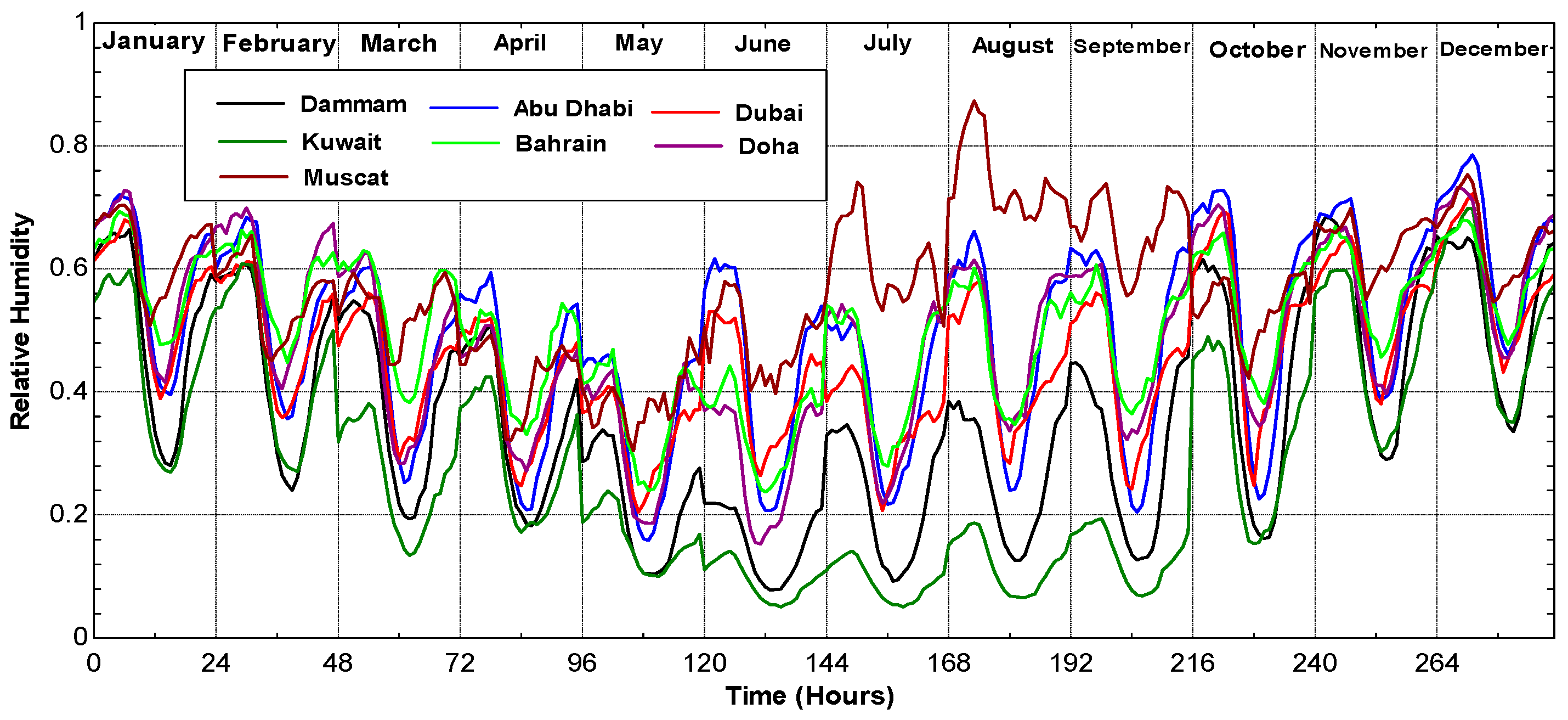
The humidity effect on the gas turbines’ performance calculations, particularly the exergy ones, was not systematically investigated.
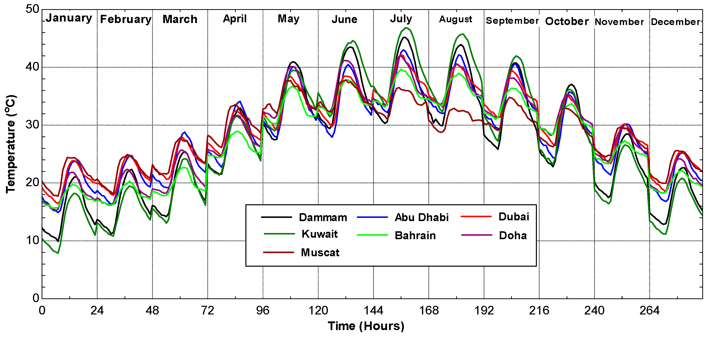
Very few studies have focused on the analysis of the effect of actual weather conditions using average hourly temperature and relative humidity for several Gulf cities.
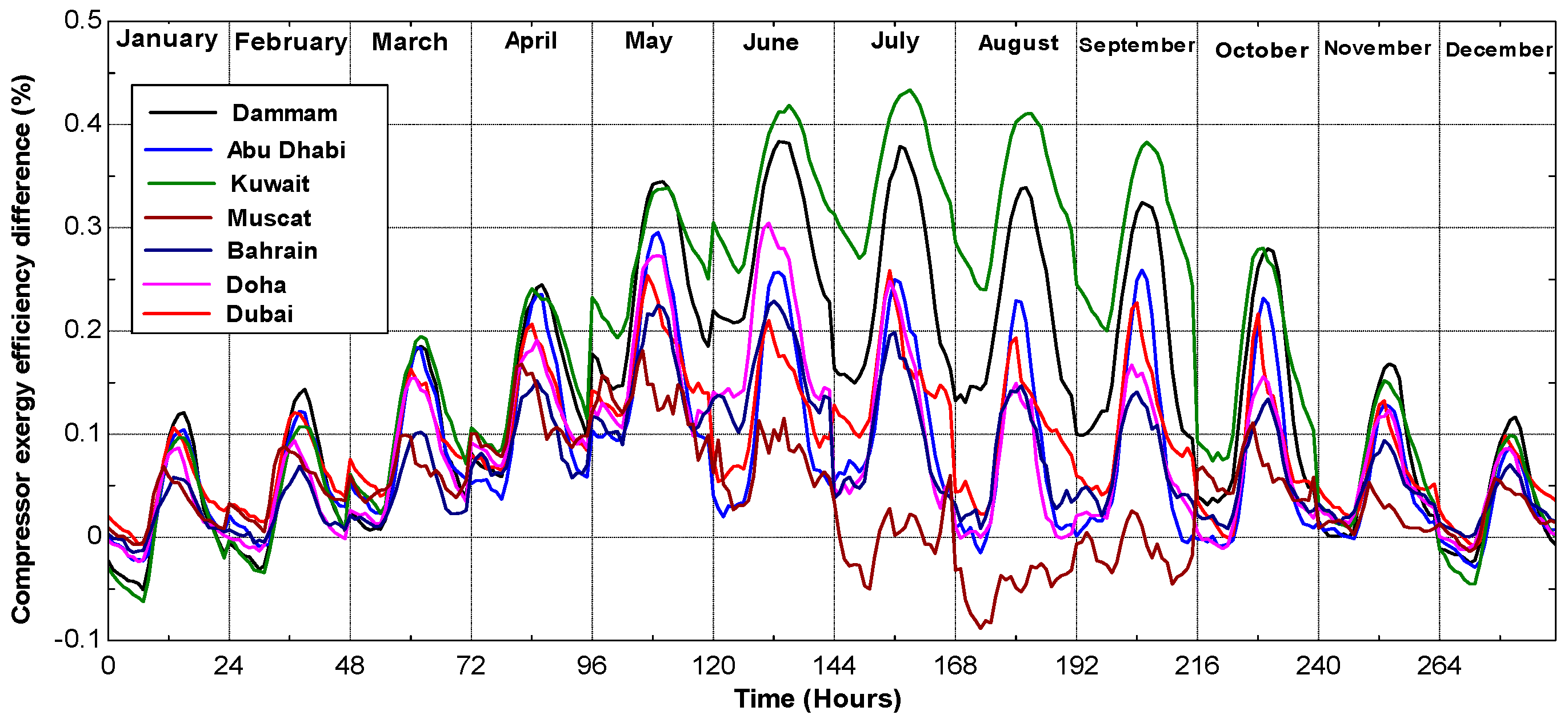
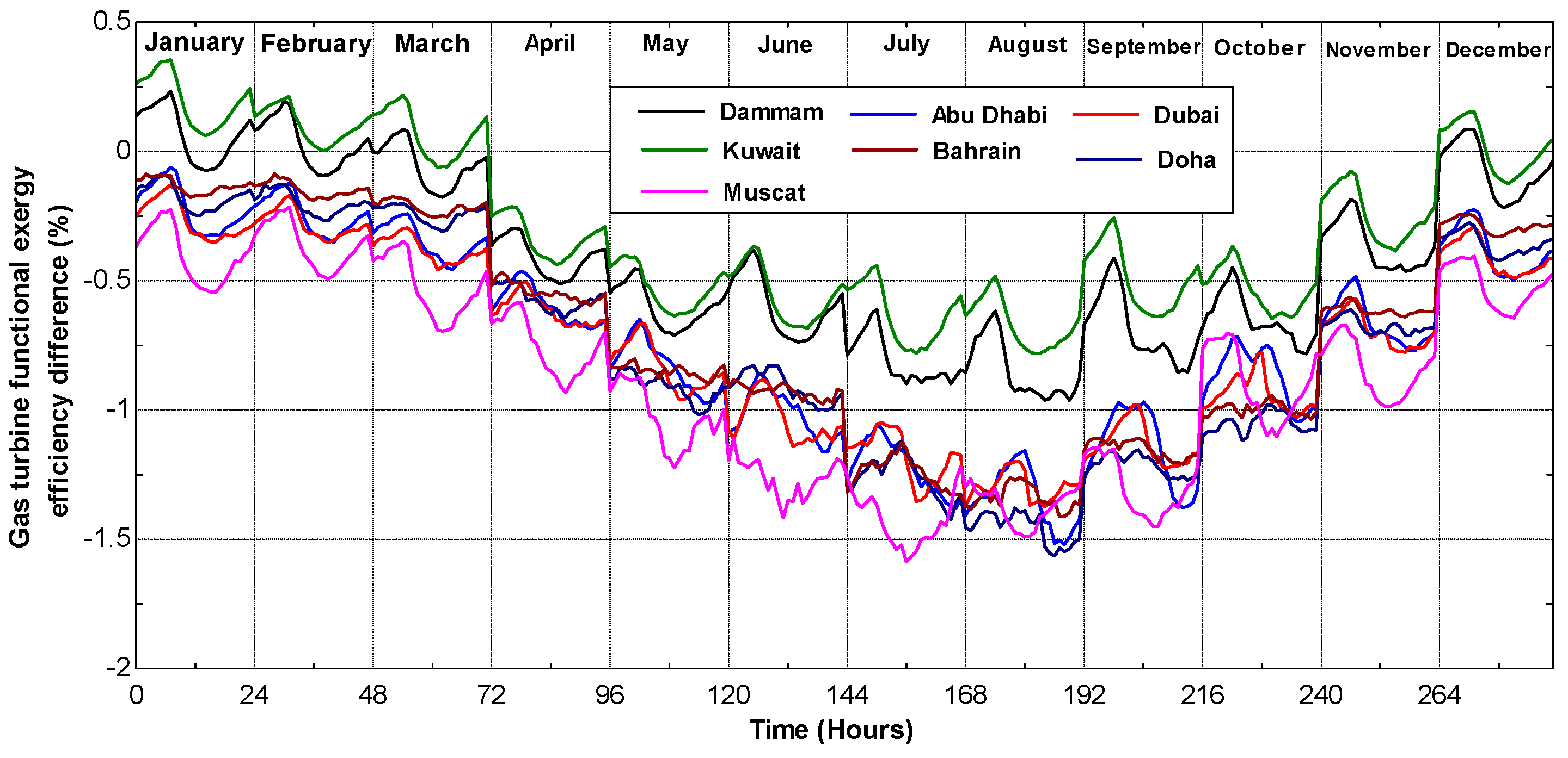
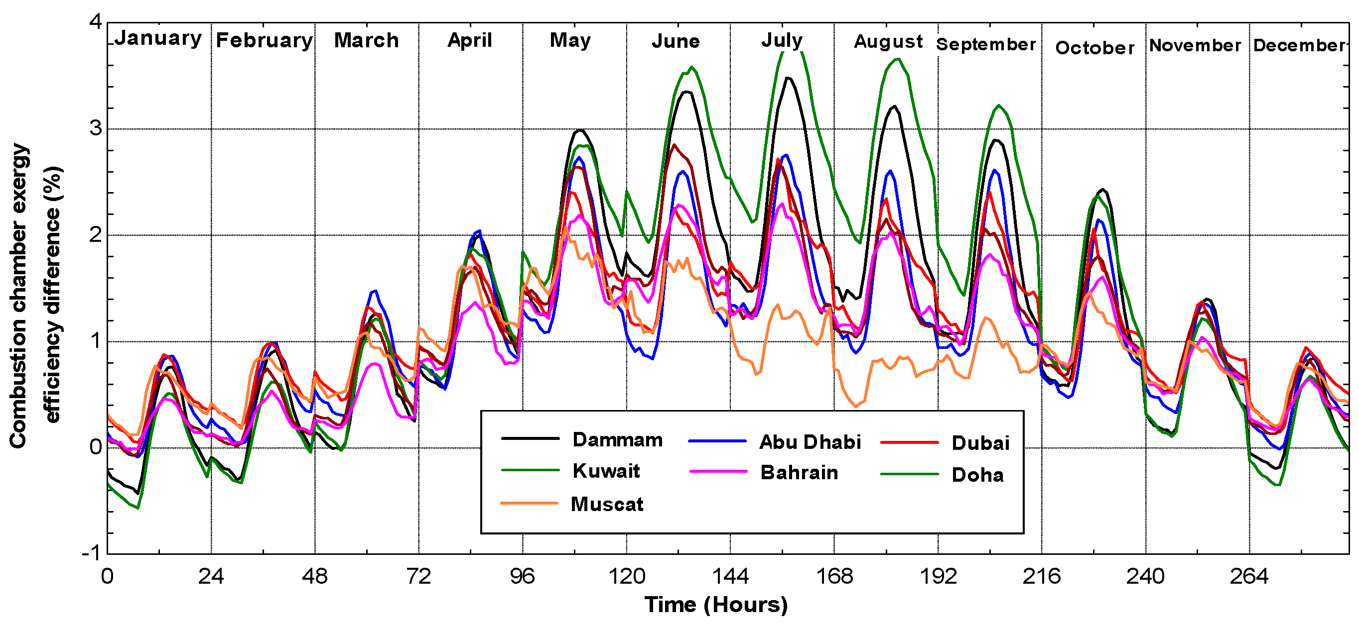
The aim of this paper is to present a theoretical energy and exergy analysis of typical gas turbines using average hourly temperature and relative humidity for selected Arab Gulf cities. The differences between the ISO and actual electricity production and fuel consumption will be evaluated and analyzed. The exergy efficiency of those power systems will be also presented taking ISO conditions as reference conditions.
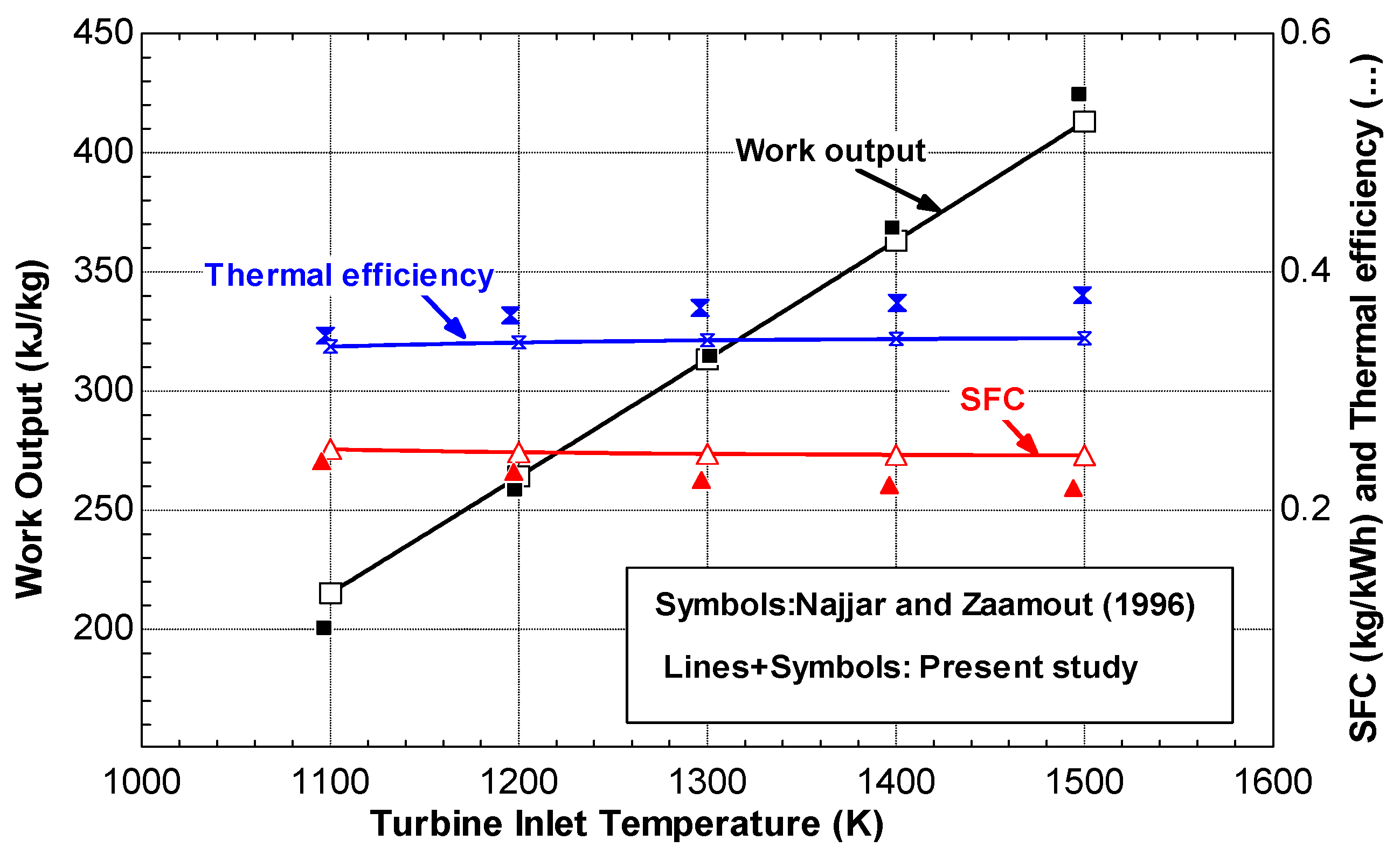
In the following, the theoretical model with the basic assumptions used in this work will be presented first. The model validation tests are outlined in
Section 3, while
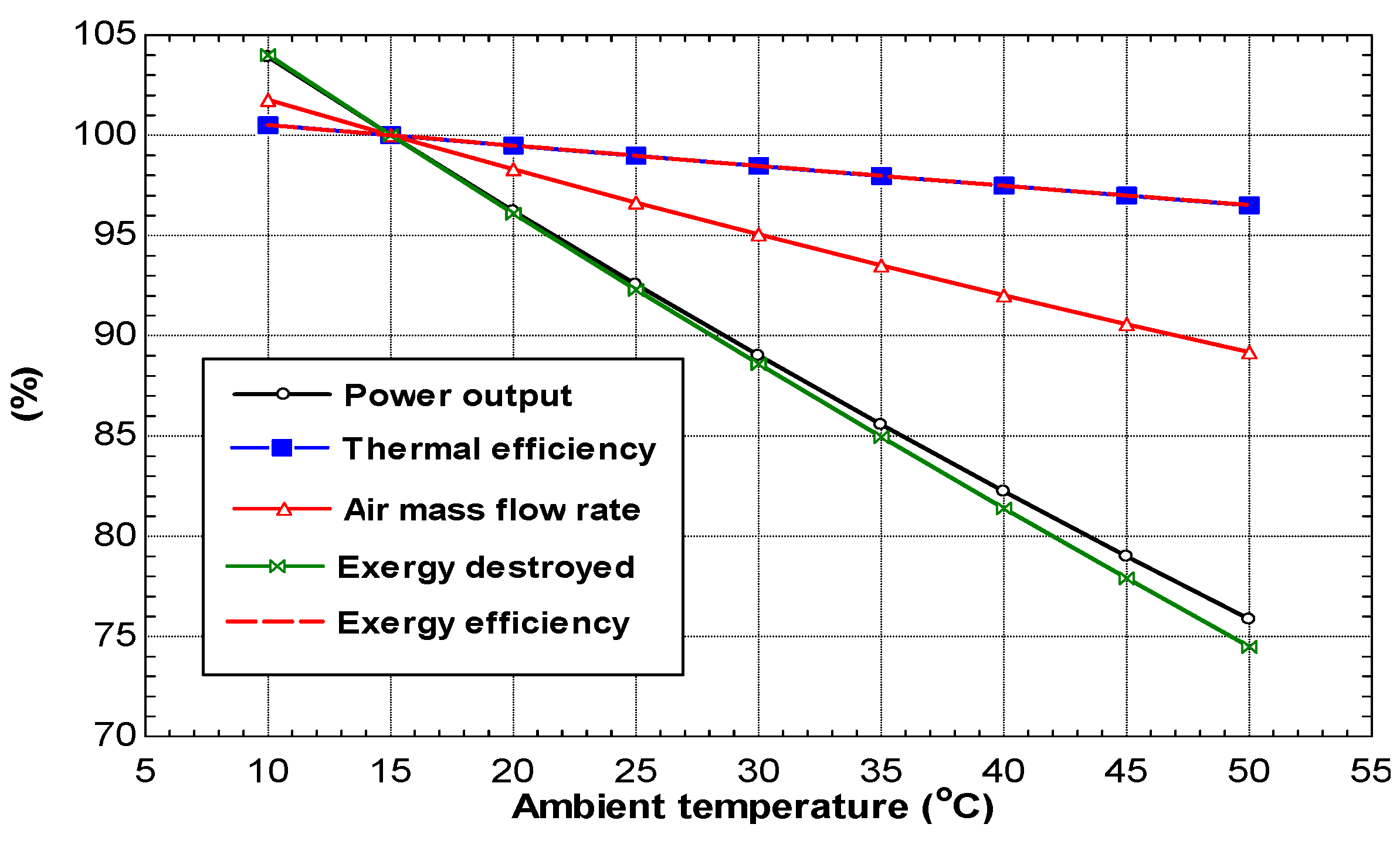
Section 4 includes the results and discussion of the first law and second law analysis.
2. Gas Turbine Cycle
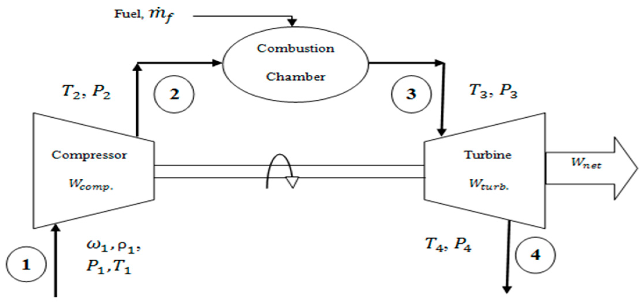
A simple gas turbine operates in the open Brayton thermodynamic cycle, as depicted in
Figure 1. As the ambient air enters the gas turbine, it passes through a compressor, which causes its pressure to increase rapidly. Fuel is then injected into the high-pressure air and ignited in the combustion chamber. The combustion products expand into the turbine and produce the work that is used to drive the generator shaft and, so, generating electricity. Part of the generated work is also used to drive the initial stage compressor.
Table 2 shows the technical parameters selected for modeling the gas turbine unit. The following basic assumptions are considered:
Each component of the gas turbine is analyzed as a control volume assumed to be at steady state with neglected pressure drop, except in the combustion chamber.
Fuel is supposed to be pure methane, and its temperature is constant and equal to the ambient temperature.
All components of the system are operated under adiabatic conditions. In particular, the combustion chamber is considered as an insulated chamber.
All fluid thermo-physical properties are modeled as temperature and pressure dependent.
Kinetic and potential energy and exergy variations in different components of the system and in the pipelines are neglected.
The ISO conditions are considered as the reference state conditions.
Based on the above assumptions, the general from of the governing equations can be expressed based on the first and second laws of thermodynamics as:
where
,
Q,
W and
h are the mass flow rate, heat transfer, work and specific enthalpy, respectively.
,
,
,
and
are the exergy input, exergy output, exergy associated with heat transfer, exergy associated with work and exergy destroyed, respectively. The specific flow exergy at any thermodynamic state is equal to [
28]:
is the specific entropy; the subscript 0 refers to the reference state conditions. The mass flow rate of the moist inlet air is:
where
is the moist air density and
is the humidity ratio (the ratio of the mass of water vapor to the mass of dry air). Those variables are functions of air inlet conditions (
T1,
P1 and
). The moist air density is calculated based on the ambient conditions. The compression work can be estimated as:
where
is the dry air mass flow rate,
rc is the compressor pressure ratio,
is the ratio of air specific heat,
is the air specific heat at constant pressure and
is the compressor is entropic efficiency that can be evaluated as [
29]:
The air specific heat at constant pressure can be calculated as [
26]:
For
:
and
in Equation (6) are the specific enthalpies of the vapor at the inlet and outlet of the compressor, respectively. The saturation pressure (
) of water vapor depends on the absolute humidity as:
The total temperature and pressure of the moist air leaving the compressor can be evaluated as:
The exergy at the inlet and outlet of the compressor can be calculated as:
The exergy destroyed in the compressor can be evaluated as:
Simplifying Equations (12)–(14), the exergy destroyed in the compressor becomes:
The heat added to the combustion chamber is:
where
is the fuel mass flow rate,
LCV is its lower calorific value and
is the combustion chamber efficiency. The fuel consumption rate can be calculated as follows:
where
is the combustion gases’ specific heat at constant pressure and
is the specific enthalpy of vapor at the outlet of the combustion chamber. The combustion chamber discharge pressure
can be estimated as:
where
is the percentage combustion chamber pressure loss.
The specific flow exergy of fuel is given as [
18,
31,
32]:
where
A is the fuel chemical energy level. The parameters a and b are equal to one and four, respectively, for methane (CH
4) [
18]. As the combustion products are assumed to behave as an ideal gas, the exergy rate of the flue gas after the combustion chamber can be calculated as:
is the total mass of working fluid flowing through the turbine and equals:
where
is the fuel to air ratio defined as
is the gas specific heat at constant pressure and
is the gas constant. Therefore, the exergy balance of the combustion chamber is:
The total work produced by the turbine can be estimated as:
where
is the gas specific ratio, and
is the turbine isentropic efficiency and can be evaluated as [
29]:
The exergy rate of the flue gas after the turbine can be estimated as:
The exergy balance for the adiabatic process in the turbine can be evaluated as:
Similarly as the compressor, by simplifying Equations (20), (25) and (26) the exergy destroyed in the turbine becomes:
Finally, the net power of the gas turbine can be calculated as:
The thermal efficiency of the gas turbine cycle is:
The exergy destroyed of a gas turbine is a summation of the exergies destroyed of the gas turbine components:
The functional exergy efficiency of the gas turbine and those of its components can be expressed as [
28]:
The monthly and annual power production of the gas turbine is:
is the monthly power production;
N is the number of days in that month;
i refers to the time of the day;
is the annual power production; and
j represents the month. The monthly and annual fuel consumption rates are:
The difference between the actual and ISO performance of a gas turbine can be expressed as:
D refers to the performance parameters of a gas turbine, and p represents the time of the day or month or year.
It is of interest to mention that the above governing equations are based on mass, energy and exergy balances for the whole gas turbine unit and its main components under steady-state conditions. Such an approach has been widely used in similar previous works (see, for instance, [
8,
11,
12,
13,
14,
19,
22,
26]). It is assumed the changes in the ambient conditions and their effect on the gas turbine performance and components parameters would not affect the steady-state behavior of the power system.


