
Entropy Generation and Heat Transfer Performances of Al2O3-Water Nanofluid Transitional Flow in Rectangular Channels with Dimples and Protrusions


Abstract
:
1. Introduction
2. Physical Model and Numerical Methods
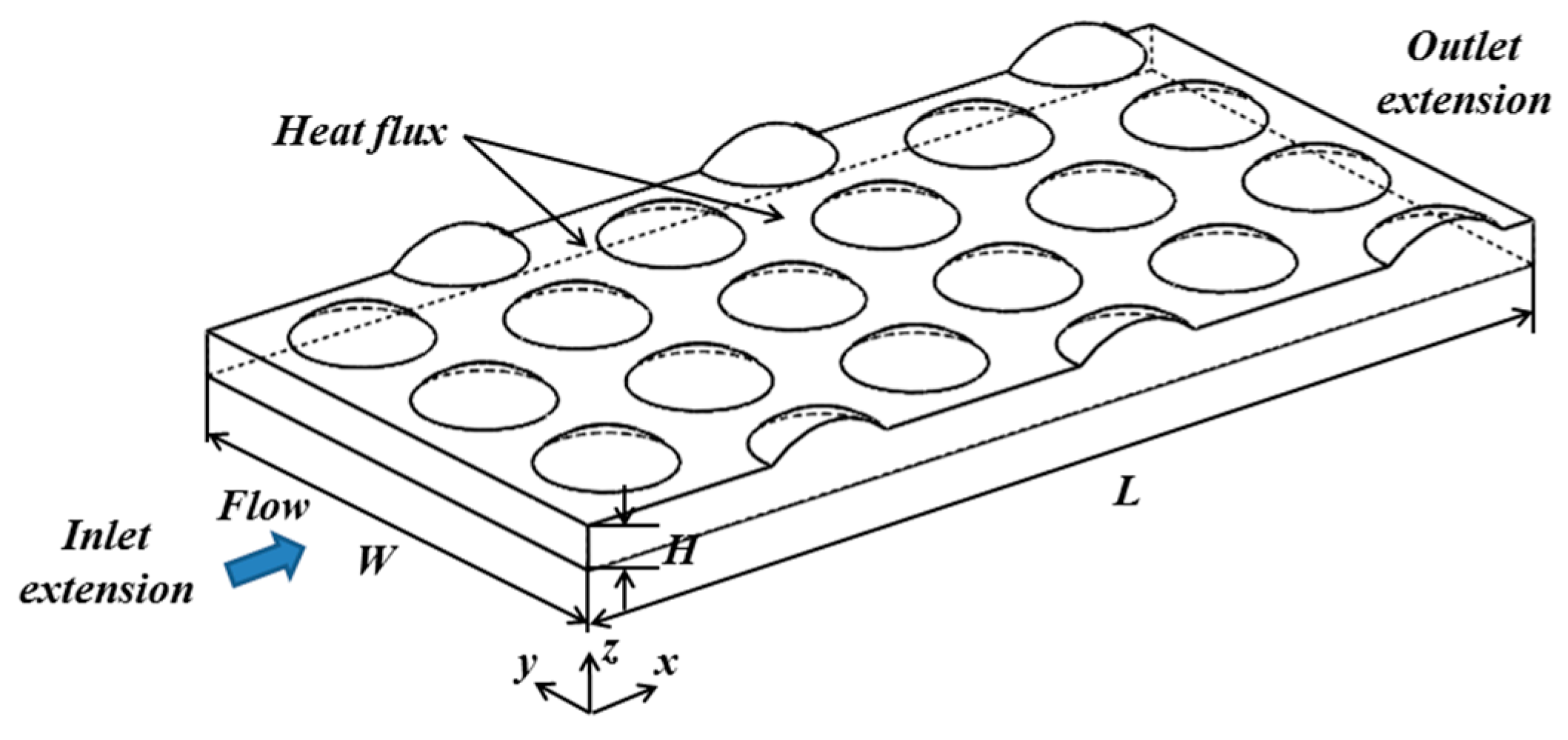
2.1. Physical Model and Numerical Method
2.2. Physical Property of Nanofluid
- Density model ρ:
- Brinkman viscosity model μ [7], which is the most common relation to calculate the viscosity in the entropy generation problems:
- Bruggeman thermal conductivity model k [11] that can be applied to spherical particle with various concentrations:
2.3. Data Reduction
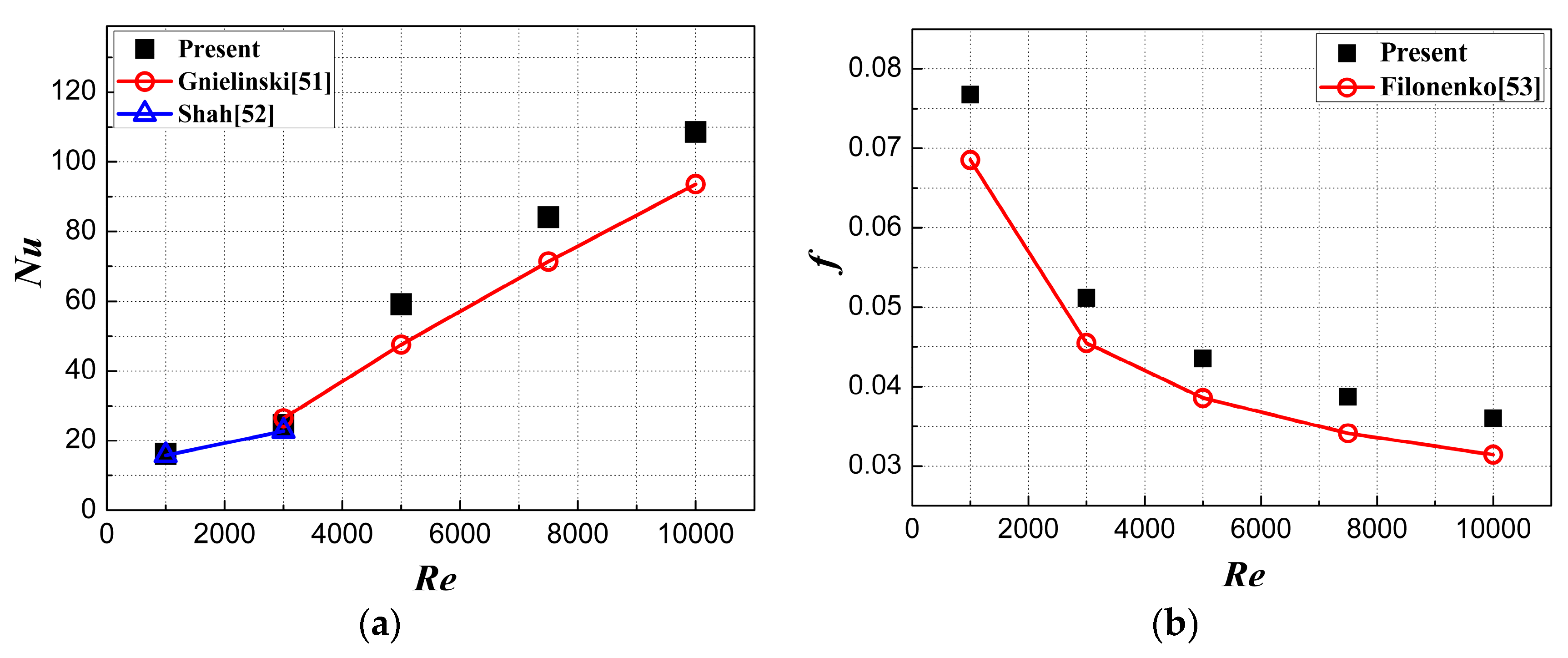
2.4. Method Validation and Grid Independence Study
- Gnielinski:where , f is given as Filonenko Equation and L is the length of the domain considered. Prf and Prw are the Prandtl numbers based on the average fluid temperature and wall temperature, respectively.
- Filonenko:
- Shah:
3. Results and Discussion
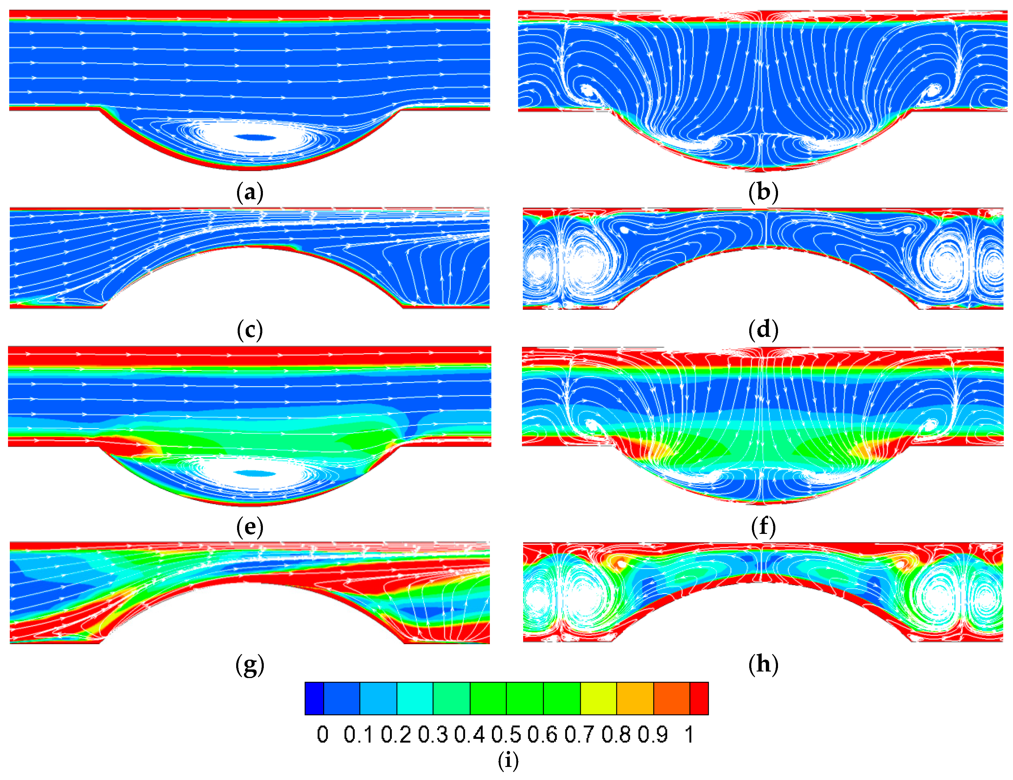
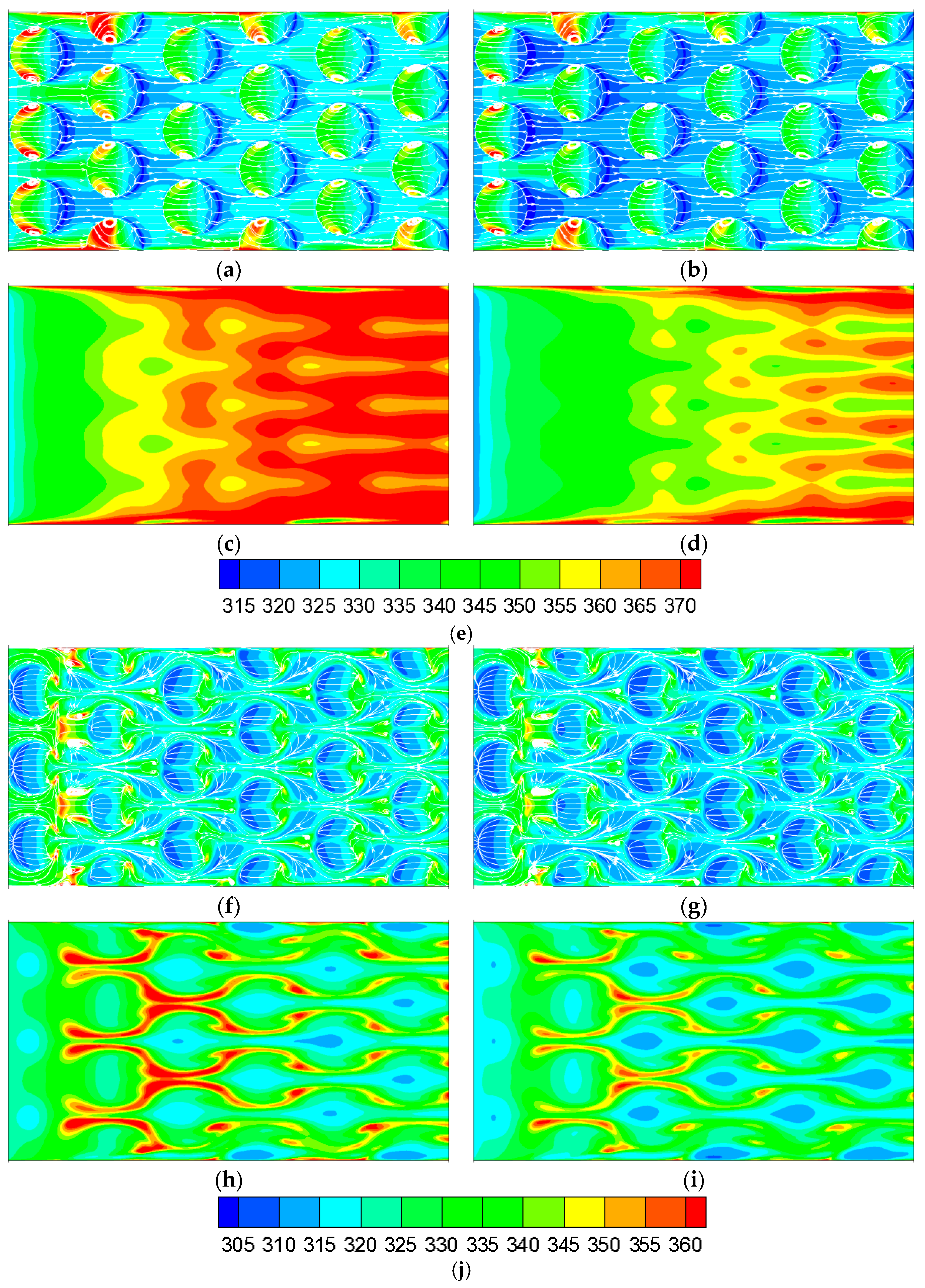
3.1. Flow Regimes and Flow Structures
3.2. Entropy Generation Analysis
3.2.1. Effect of Nanofluids on Entropy Generation
3.2.2. Effect of Dimples/Protrusions on Entropy Generation
3.3. Heat Transfer Performance Analysis
4. Conclusions
- When Re reaches 10,000 or even higher, the mainstream has completely turned into turbulent flow, and Re range in this study covers laminar flow, transitional flow and turbulent flow.
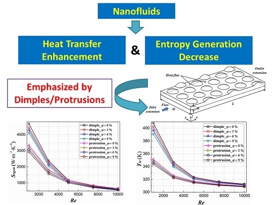
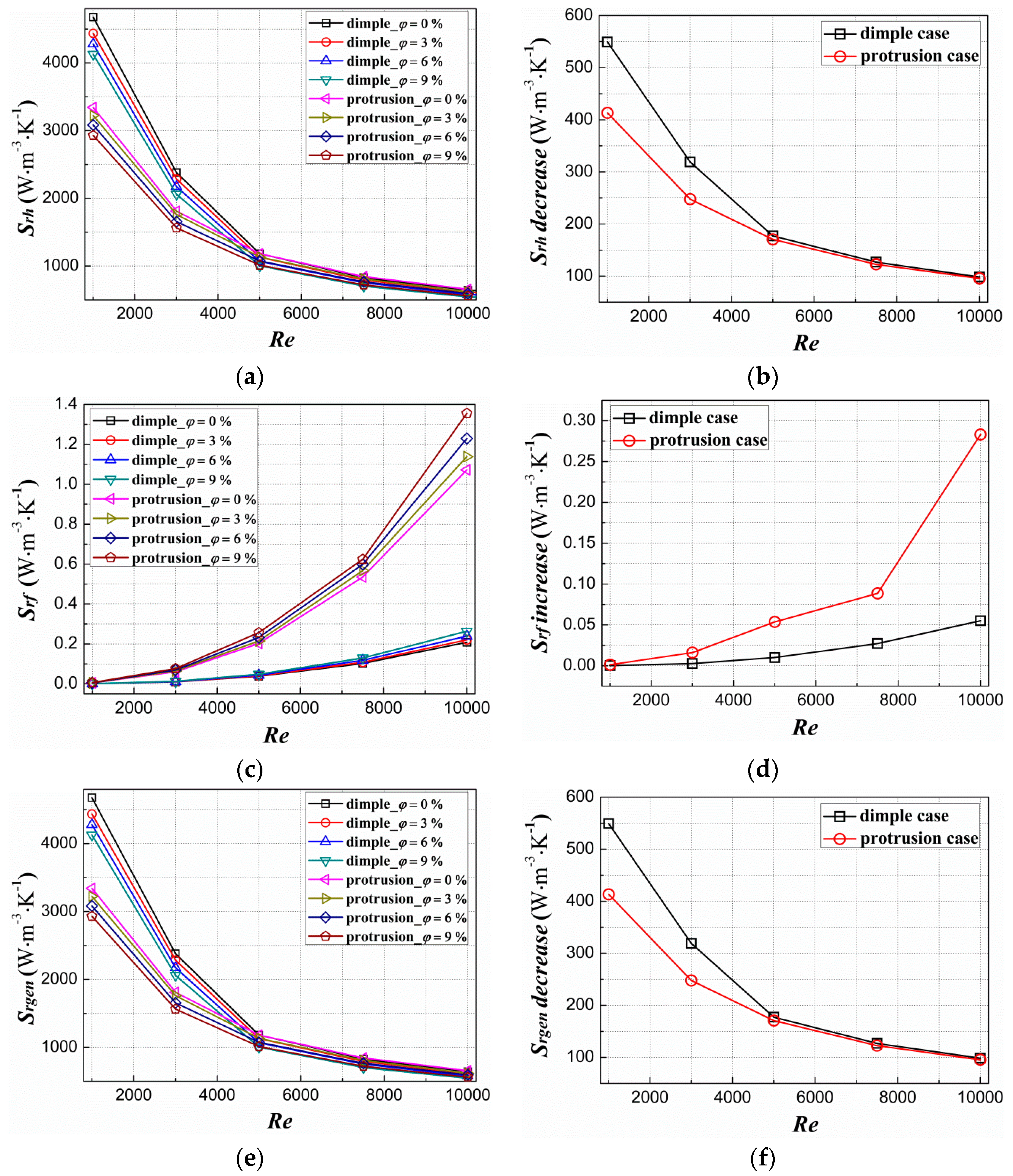
- The Srh keeps decreasing at a given Re with an increasing volume fraction, and the decrease of the Srh owing to nanofluids declines with the increase in Re. The employment of nanofluid increases Srf at a given Re, and Srf further ascends with an increasing volume fraction, in which the effect gets more significant with the growth in Re. The Srgen expresses a variation tendency with high similarity with that of Srh under the Re range in this study.
- The dimple-case has great benefit in decreasing entropy generation compared to smooth channel both in heat transfer entropy generation rate and friction entropy generation rate. The protrusion-case suffers from penalty of distinct friction entropy generation rate increase though it performs well in heat transfer entropy generation rate decline.
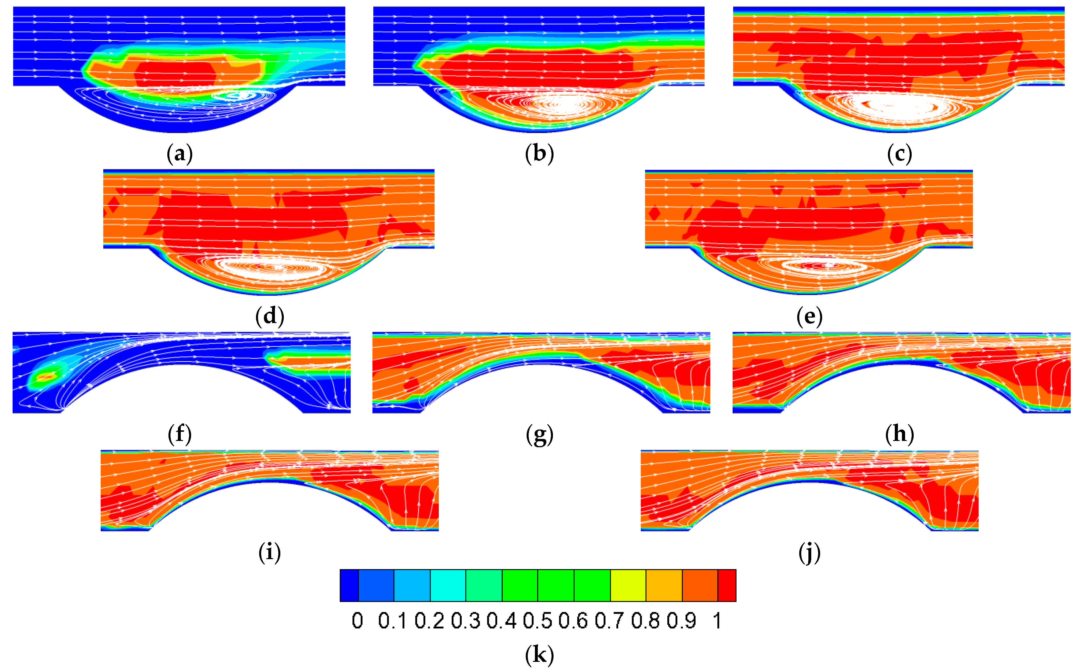
- The keeps at a quite low level in the major area of the domain, and the high regions are mainly located near the boundary layer and the local vortices. There is a low region near dimple trailing edge, and high regions are detected in accordance with low velocity areas.
- The high temperature regions’ area notably decreases and the low temperature regions’ area markedly increases with an increasing volume fraction. The entire temperature level prominently declines almost at all regions in both the structured and smooth surfaces.
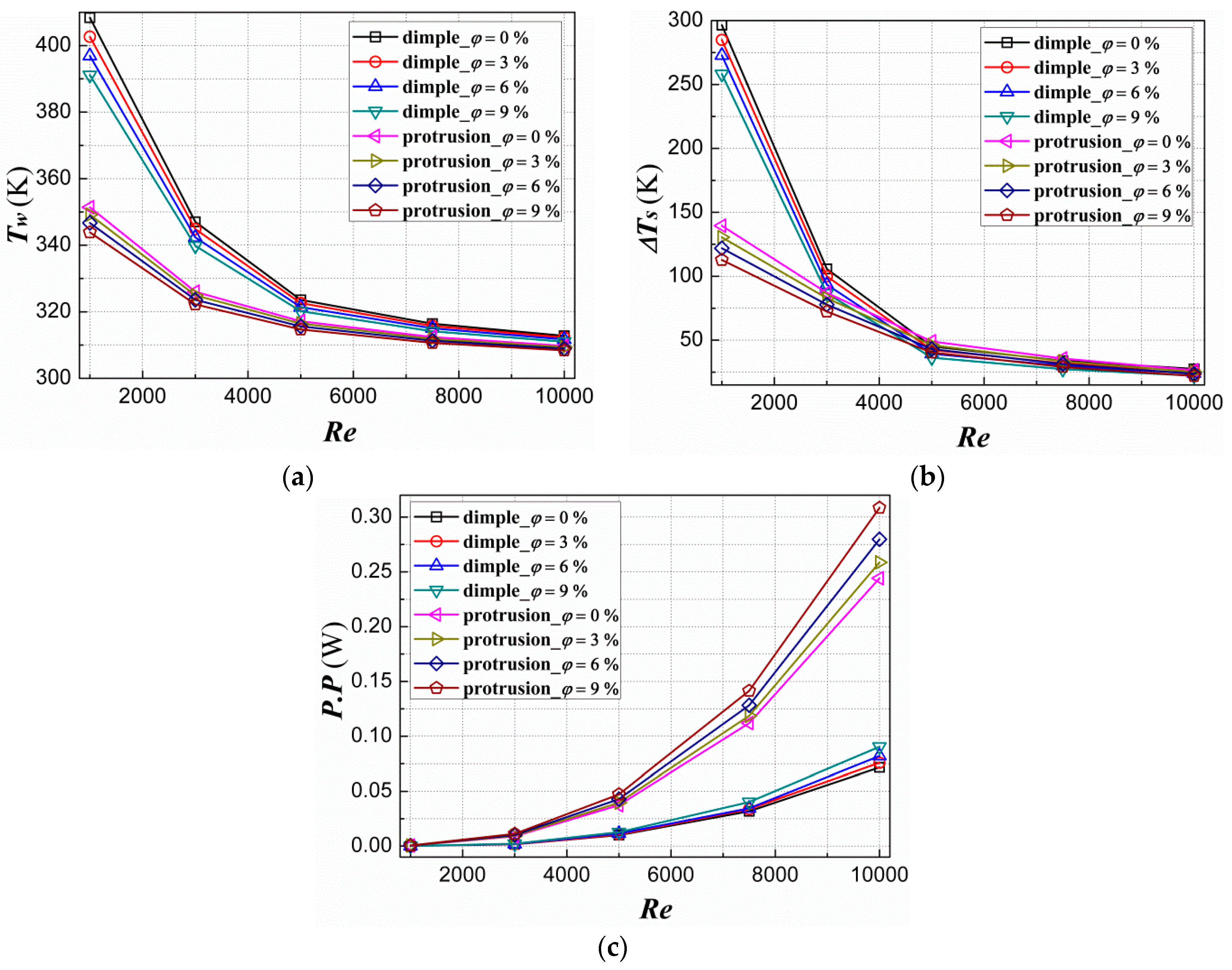
- With the increase in nanofluids volume fraction, Tw keeps decreasing, ΔTs declines and P.P ascends in both dimple-case and protrusion-case at a given Re.
- Conclusively, it is preferred to employ nanofluids to obtain great heat transfer enhancement performance and significant entropy generation decrease under laminar flow. It is also recommended that protrusions be adopted under laminar flow for its superior heat transfer enhancement performance and remarkable entropy generation decrease. Besides, dimples are preferable under turbulent flow in order to avoid high pumping power and excessive friction entropy generation increase.
Author Contributions
Conflicts of Interest
Abbreviations
| A | wall area (m3) |
| Cp | specific heat (J/kg∙K) |
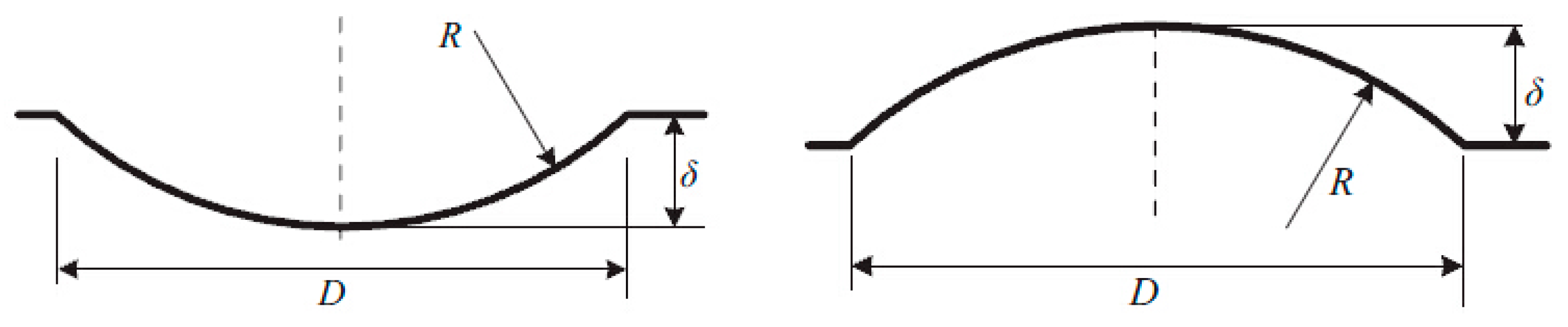
| D | dimple/protrusion print diameter (m) |
| Dh | hydraulic diameter (m) |
| f | resistance coefficient |
| H | channel height (m) |
| k | thermal conductivity (W/m·K) |
| L | heated section length (m) |
| M | mass flow rate (kg/s) |
| Nu | Nusselt number |
| P.P | pumping power (W) |
| Re | Reynolds number |
| local total entropy generation rate (W/m3·K) | |
| local heat transfer entropy generation rate (W/m3·K) | |
| local friction entropy generation rate (W/m3·K) | |
| dimensionless local total entropy generation rate | |
| dimensionless local heat transfer entropy generation rate | |
| dimensionless local friction entropy generation rate | |
| Srgen | average total entropy generation rate (W/m3·K) |
| Srh | average heat transfer entropy generation rate (W/m3·K) |
| Srf | average friction entropy generation rate (W/m3·K) |
| Srh0 | average heat transfer entropy generation rate of smooth channel (W/m3·K) |
| Srf0 | average friction entropy generation rate of smooth channel (W/m3·K) |
| Tw | wall temperature (K) |
| Um,in | inlet average velocity (m/s) |
| W | channel height (m) |
| x, y, z | Cartesian coordinates (m) |
| Greek Characters | |
| δ | dimple/protrusion depth (m) |
| φ | volume fraction (%) |
| γ | turbulence intermittency |
| ρ | density (kg/m3) |
| μ | viscosity (Pa·s) |
| ΔTs | temperature uniformity (K) |
| ΔP | pressure drop (Pa) |
| Subscripts | |
| max | maximum value |
| min | minimum value |
| nf | nanofluid |
| f | basefluid |
| p | nanoparticle |
| in | inlet |
References
- Choi, U.S.; Eastman, J.A. Enhancing thermal conductivity of fluids with nanoparticles. In Proceedings of the 1995 International Conference on Mechanical Engineering Congress and Exhibition, San Francisco, CA, USA, 12–17 November 1995.
- Saidur, R.K.; Leong, Y.; Mohammad, H.A. A review on applications and challenges of nanofluids. Renew. Sustain. Energy Rev. 2011, 15, 1646–1668. [Google Scholar] [CrossRef]
- Hadad, Z.; Oztop, H.F.; Abu-Nada, E.; Mataoui, A. A review on natural convective heat transfer of nanofluids. Renew. Sustain. Energy Rev. 2012, 16, 5363–5378. [Google Scholar] [CrossRef]
- Khanafer, K.; Vafai, K. A critical synthesis of thermophysical characteristics of nanofluids. Int. J. Heat Mass Transf. 2011, 54, 4410–4428. [Google Scholar] [CrossRef]
- Mahbubul, I.M.; Saidur, R.; Amalina, M.A. Latest developments on the viscosity of nanofluids. Int. J. Heat Mass Transf. 2012, 55, 874–885. [Google Scholar] [CrossRef]
- Fan, J.; Wang, L. Review of heat conduction in nanofluids. J. Heat Transf. 2011, 133, 040801. [Google Scholar] [CrossRef]
- Brinkman, H.C. The viscosity of concentrated suspensions and solutions. J. Chem. Phys. 1952, 20, 571. [Google Scholar] [CrossRef]
- Corcione, M. Heat transfer features of buoyancy-driven nanofluids inside rectangular enclosures differentially heated at the sidewalls. Int. J. Therm. Sci. 2010, 49, 1536–1546. [Google Scholar] [CrossRef]
- Duangthongsuk, W.; Wongwises, S. Measurement of temperature-dependent thermal conductivity and viscosity of TiO2-water nanofluids. Exp. Therm. Fluid Sci. 2009, 33, 706–714. [Google Scholar] [CrossRef]
- Maxwell, J.C. A Treatise Electricity Magnetism, 2nd ed.; Clarendon Press: Oxford, UK, 1881. [Google Scholar]
- Bruggeman, D.A.G. Berechnung verschiedener physikalischer Konstanten von heterogenen Substanzen. I. Dielektrizitatskonstanten und Leitfahigkeiten der Mischkorper aus isotropen Substanzen. Annalen der Physik 1935, 416, 636–664. (In German) [Google Scholar] [CrossRef]
- Hamilton, R.L.; Crosser, O.K. Thermal conductivity of heterogeneous two component systems. Ind. Eng. Chem. Fundam. 1962, 1, 182–191. [Google Scholar] [CrossRef]
- Nan, C.W.; Birringer, R.; Clarke, D.R.; Gleiter, H. Effective thermal conductivity of particulate composites with interfacial thermal resistance. J. Appl. Phys. 1997, 81, 6692–6699. [Google Scholar] [CrossRef]
- Yu, W.; Choi, S.U.S. The role of interfacial layers in the enhanced thermal conductivity of nanofluids: A renovated Maxwell model. J. Nanopart. Res. 2003, 5, 167–171. [Google Scholar] [CrossRef]
- Yu, W.; Choi, S.U.S. The role of interfacial layers in the enhanced thermal conductivity of nanofluids: A renovated Hamilton–Crosser model. J. Nanopart. Res. 2004, 6, 355–361. [Google Scholar] [CrossRef]
- Koo, J.; Kleinstreuer, C. A new thermal conductivity model for nanofluids. J. Nanopart. Res. 2004, 6, 577–588. [Google Scholar] [CrossRef]
- Feng, Y.; Kleinstreuer, C. Nanofluid convective heat transfer in a paralleldisk system. Int. J. Heat Mass Transf. 2010, 53, 4619–4628. [Google Scholar] [CrossRef]
- Machrafi, H.; Lebon, G. The role of several heat transfer mechanisms on the enhancement of thermal conductivity in nanofluids. Contin. Mech. Thermodyn. 2016. [Google Scholar] [CrossRef]
- Seyf, H.R.; Feizbakhshi, M. Computational analysis of nanofluid effects on convective heat transfer enhancement of micro-pin-fin heat sinks. Int. J. Therm. Sci. 2012, 58, 168–179. [Google Scholar] [CrossRef]
- Selvakumar, P.; Suresh, S. Convective performance of CuO/water nanofluid in an electronic heat sink. Exp. Therm. Fluid Sci. 2012, 40, 57–63. [Google Scholar] [CrossRef]
- Diao, Y.H.; Liu, Y.; Wang, R.; Zhao, Y.H.; Guo, X.; Tang, X. Effects of nanofluids and nanocoatings on the thermal performance of an evaporator with rectangular microchannels. Int. J. Heat Mass Transf. 2013, 67, 183–193. [Google Scholar] [CrossRef]
- Wen, D.S.; Ding, Y.L. Experimental investigation into convective heat transfer of nanofluids at the entrance region under laminar flow conditions. Int. J. Heat Mass Transf. 2004, 47, 5181–5188. [Google Scholar] [CrossRef]
- Suresh, S.; Chandrasekar, M.; Selvakumar, P. Experimental studies on heat transfer and friction factor characteristics of CuO/water nanofluid under laminar flow in a helically dimpled tube. Heat Mass Transf. 2012, 48, 683–694. [Google Scholar] [CrossRef]
- Suresh, S.; Chandrasekar, M.; Chandra Sekhar, S. Experimental studies on heat transfer and friction factor characteristics of CuO/water nanofluid under turbulent flow in a helically dimpled tube. Exp. Therm. Fluid Sci. 2011, 35, 542–549. [Google Scholar] [CrossRef]
- Vakili, M.; Mohebbi, A.; Hashemipour, H. Experimental study on convective heat transfer of TiO2 nanofluids. Heat Mass Transf. 2013, 49, 1159–1165. [Google Scholar] [CrossRef]
- Xuan, Y.M.; Li, Q. Investigation on Convective Heat Transfer and Flow Features of Nanofluids. ASME J. Heat Transf. 2003, 125, 151–155. [Google Scholar] [CrossRef]
- Gavili, A.; Isfahani, T.D.; Zabihi, F.; Hadi, I. The effect of real viscosity on the heat transfer of water based Al2O3 nanofluids in a two-sided lid-driven differentially heated rectangular cavity. Heat Mass Transf. 2013, 49, 1433–1445. [Google Scholar] [CrossRef]
- Mohammed, H.A.; Al-Shamani, A.N.; Sheriff, J.M. Thermal and hydraulic characteristics of turbulent nanofluids flow in a rib–groove channel. Int. Commun. Heat Mass Transf. 2012, 39, 1584–1594. [Google Scholar] [CrossRef]
- Oztop, H.F.; Al-Salem, K. A review on entropy generation in natural and mixed convection heat transfer for energy systems. Renew. Sustain. Energy Rev. 2012, 16, 911–920. [Google Scholar] [CrossRef]
- Singh, P.K.; Anoop, K.B.; Sundararajan, T.; Das, S.K. Entropy generation due to flow and heat transfer in nanofluids. Int. J. Heat Mass Transf. 2010, 53, 4757–4767. [Google Scholar] [CrossRef]
- Li, J.; Kleinstreuer, C. Entropy generation analysis for nanofluid flow in microchannels. J. Heat Transf. 2010, 132, 122401. [Google Scholar] [CrossRef]
- Moghaddami, M.; Mohammadzade, A.; Varzane Esfehani, S.A. Second law analysis of nanofluid flow. Energy Convers. Manag. 2011, 52, 1397–1405. [Google Scholar] [CrossRef]
- Leong, K.Y.; Saidur, R.; Mahlia, T.M.I.; Yau, Y.H. Entropy generation analysis of nanofluid flow in a circular tube subjected to constant wall temperature. Int. Commun. Heat Mass Transf. 2012, 39, 1169–1175. [Google Scholar] [CrossRef]
- Mahian, O.; Mahmud, S.; Zeinali Heris, S. Analysis of entropy generation between co-rotating cylinders using nanofluids. Energy 2012, 44, 438–446. [Google Scholar] [CrossRef]
- Shahi, M.; Mahmoudi, A.H.; Raouf, A.H. Entropy generation due to natural convection cooling of a nanofluid. Int. Commun. Heat Mass Transf. 2011, 38, 972–983. [Google Scholar] [CrossRef]
- Mahmoudi, A.H.; Talebi, F.; Shahi, M. Entropy generation due to natural convection cooling of a horizontal heat source mounted inside a square cavity filled with nanofluid. Heat Transf. Res. 2012, 43, 19–46. [Google Scholar]
- Khorasanizadeh, H.; Nikfar, M.; Amani, J. Entropy generation of Cu–water nanofluid mixed convection in a cavity. Eur. J. Mech. B Fluids 2013, 37, 143–152. [Google Scholar] [CrossRef]
- Khorasanizadeh, H.; Nikfar, M.; Amani, J. Numerical investigation of Cu–water nanofluid natural convection and entropy generation within a cavity with an embedded conductive baffle. Sci. Iran 2012, 19, 1996–2003. [Google Scholar] [CrossRef]
- Esmaeilpoura, M.; Abdollahzadeh, M. Free convection and entropy generation of nanofluid inside an enclosure with different patterns of vertical wavy walls. Int. J. Therm. Sci. 2012, 52, 127–136. [Google Scholar] [CrossRef]
- Cho, C.C.; Chen, C.L.; Chen, C.K. Natural convection heat transfer and entropy generation in wavy-wall enclosure containing water-based nanofluid. Int. J. Heat Mass Transf. 2013, 61, 749–758. [Google Scholar] [CrossRef]
- Boghrati, M.; Bajestan, E.E.; Etminan, V. Entropy generation minimization of confined nanofluids laminar flow around a block. In Proceedings of the ASME 10th Biennial Conference on Engineering Systems and Analysis, Istanbul, Turkey, 12–14 July 2010.
- Sarkar, S.; Ganguly, S.; Dalal, A. Analysis of entropy generation during mixed convection heat transfer of nanofluids past a square cylinder in vertically upward flow. J. Heat Transf. 2012, 134, 122501. [Google Scholar] [CrossRef]
- Leong, K.Y.; Saidur, R.; Khairulmaini, M.; Michael, Z.; Kamyar, A. Heat transfer and entropy analysis of three different types of heat exchangers operated with nanofluids. Int. Commun. Heat Mass Transf. 2012, 39, 838–843. [Google Scholar] [CrossRef]
- Matin, M.H.; Nobari, M.R.H.; Jahangiri, P. Entropy analysis in mixed convection MHD flow of nanofluid over a non-linear stretching sheet. J. Therm. Sci. Technol. 2012, 7, 104–119. [Google Scholar] [CrossRef]
- Selimefendigil, F.; Oztop, H.F.; Abu-Hamdeh, N. Natural convection and entropy generation in nanofluid filled entrapped trapezoidal cavities under the influence of magnetic field. Entropy 2016, 18, 43. [Google Scholar] [CrossRef]
- Menter, F.R. Two-equation eddy-viscosity turbulence models for engineering applications. AIAA J. 1994, 32, 1598–1605. [Google Scholar] [CrossRef]
- Menter, F.R.; Langtry, R.B.; Likki, S.R.; Suzen, Y.B.; Huang, P.G.; Volker, S. A correlation-based transition model using local variables—Part I: Model formulation. J. Turbomach. 2006, 128, 413–422. [Google Scholar] [CrossRef]
- Manca, O.; Mesolella, P.; Nardini, S.; Ricci, D. Numerical study of a confined slot impinging jet with nanofluids. Nanoscale Res. Lett. 2011, 6, 1–16. [Google Scholar] [CrossRef] [PubMed]
- Ho, C.J.; Chen, M.W.; Li, Z.W. Numerical simulation of natural convection of nanofluid in a square enclosure: Effects due to uncertainties of viscosity and thermal conductivity. Int. J. Heat Mass Transf. 2008, 51, 4506–4516. [Google Scholar] [CrossRef]
- Bejan, A. Entropy Generation through Heat and Fluid Flow; Wiley: New York, NY, USA, 1982. [Google Scholar]
- Gnielinski, V. New equations for heat transfer in turbulent pipe and channel flows. Int. Chem. Eng. 1976, 16, 359–368. [Google Scholar]
- Shah, R.K.; London, A.L. Laminar Flow Forced Convection in Ducts: A Source Book for Compact Heat Exchanger Analytical Data; Academic Press: New York, NY, USA, 1978. [Google Scholar]
- Flionenko, G.K. Hydraulic Resistance in Pipes. Teploenergetika 1954, 1, 40–44. (In Russian) [Google Scholar]


| Case | Turbulator Structure | Volume Fraction (φ) | Case | Turbulator Structure | Volume Fraction (φ) | Re |
|---|---|---|---|---|---|---|
| Case 1 | dimples | 0% | Case 5 | protrusions | 0% | 1000~40,000 |
| Case 2 | dimples | 3% | Case 6 | protrusions | 3% | 1000~40,000 |
| Case 3 | dimples | 6% | Case 7 | protrusions | 6% | 1000~40,000 |
| Case 4 | dimples | 9% | Case 8 | protrusions | 9% | 1000~40,000 |
| Mesh | Grid Number (million) | Nu | Difference (%) | f × 102 | Difference (%) |
|---|---|---|---|---|---|
| Mesh 1 | 0.582 | 73.467 | 7.367 | 6.634 | 8.134 |
| Mesh 2 | 1.496 | 70.235 | 2.644 | 6.383 | 4.042 |
| Mesh 3 | 2.889 | 68.813 | 0.566 | 6.172 | 0.603 |
| Mesh 4 | 4.541 | 68.426 | Reference | 6.135 | Reference |
© 2016 by the authors; licensee MDPI, Basel, Switzerland. This article is an open access article distributed under the terms and conditions of the Creative Commons Attribution (CC-BY) license (http://creativecommons.org/licenses/by/4.0/).
Share and Cite
Xie, Y.; Zheng, L.; Zhang, D.; Xie, G. Entropy Generation and Heat Transfer Performances of Al2O3-Water Nanofluid Transitional Flow in Rectangular Channels with Dimples and Protrusions. Entropy 2016, 18, 148. https://doi.org/10.3390/e18040148
Xie Y, Zheng L, Zhang D, Xie G. Entropy Generation and Heat Transfer Performances of Al2O3-Water Nanofluid Transitional Flow in Rectangular Channels with Dimples and Protrusions. Entropy. 2016; 18(4):148. https://doi.org/10.3390/e18040148
Chicago/Turabian StyleXie, Yonghui, Lu Zheng, Di Zhang, and Gongnan Xie. 2016. "Entropy Generation and Heat Transfer Performances of Al2O3-Water Nanofluid Transitional Flow in Rectangular Channels with Dimples and Protrusions" Entropy 18, no. 4: 148. https://doi.org/10.3390/e18040148
APA StyleXie, Y., Zheng, L., Zhang, D., & Xie, G. (2016). Entropy Generation and Heat Transfer Performances of Al2O3-Water Nanofluid Transitional Flow in Rectangular Channels with Dimples and Protrusions. Entropy, 18(4), 148. https://doi.org/10.3390/e18040148