Article

On the Virtual Cell Transmission in Ultra Dense Networks

1
Department of Electronic Engineering, Xiamen University, Xiamen 361005, China
2
Tsinghua National Laboratory for Information Science and Technology, Research Institute of Information Technology, Tsinghua University, Beijing 100084, China
*
Author to whom correspondence should be addressed.
Entropy 2016, 18(10), 374; https://doi.org/10.3390/e18100374
Submission received: 25 June 2016 / Revised: 30 September 2016 / Accepted: 14 October 2016 / Published: 20 October 2016

Abstract

:
Ultra dense networks (UDN) are identified as one of the key enablers for 5G, since they can provide an ultra high spectral reuse factor exploiting proximal transmissions. By densifying the network infrastructure equipment, it is highly possible that each user will have one or more dedicated serving base station antennas, introducing the user-centric virtual cell paradigm. However, due to irregular deployment of a large amount of base station antennas, the interference environment becomes rather complex, thus introducing severe interferences among different virtual cells. This paper focuses on the downlink transmission scheme in UDN where a large number of users and base station antennas is uniformly spread over a certain area. An interference graph is first created based on the large-scale fadings to give a potential description of the interference relationship among the virtual cells. Then, base station antennas and users in the virtual cells within the same maximally-connected component are grouped together and merged into one new virtual cell cluster, where users are jointly served via zero-forcing (ZF) beamforming. A multi-virtual-cell minimum mean square error precoding scheme is further proposed to mitigate the inter-cluster interference. Additionally, the interference alignment framework is proposed based on the low complexity virtual cell merging to eliminate the strong interference between different virtual cells. Simulation results show that the proposed interference graph-based virtual cell merging approach can attain the average user spectral efficiency performance of the grouping scheme based on virtual cell overlapping with a smaller virtual cell size and reduced signal processing complexity. Besides, the proposed user-centric transmission scheme greatly outperforms the BS-centric transmission scheme (maximum ratio transmission (MRT)) in terms of both the average user spectral efficiency and edge user spectral efficiency. What is more, interference alignment based on the low complexity virtual cell merging can achieve much better performance than ZF and MRT precoding in terms of average user spectral efficiency.

1. Introduction

With the rapid development of smart phones and all kinds of other mobile computing devices, mobile data traffic volume has grown explosively in recent years. Cisco points out in [1] that by the end of 2015, global mobile data traffic had grown more than 4000-times compared to 2005, and the number becomes an amazing 400 million when comparing to the year of 2000. Hence, [1] predicts that there will be an 8.5-times increase in global mobile data traffic by the year of 2020. However, the past decade has also seen considerable development in the wireless communication industry. The long-term evolution (LTE) developed by the 3rd Generation Partnership Project (3GPP) has been in wide commercial use. Up to today, more mobile data traffic (almost 47 percent of the total mobile data traffic) goes through LTE than 3G. The LTE networks are seeing their capacity limit soon. As a result, it is a big challenge to realize an 8.5-times network capacity increase within five years for the network operators and vendors.
The network capacity of future wireless communication systems should be evaluated in an area capacity sense, the unit of which is bps / km 2 . Noting that bps / km 2 = bps / Hz × Hz / cell × cell / km 2 , i.e., the area capacity is equal to the product of cell spectral efficiency, system bandwidth and cell density [2]. As a result, we have three ways to boost the network capacity to cope with the 8.5-times increase of global mobile data traffic volume by 2020 [1]; each of the three ways corresponds to some key enablers for 5G [3]; for example, spectrum re-farming and high frequency transmission for bandwidth expanding, massive MIMO [4] and non-orthogonal multiple access [5] for spectral efficiency improvement and ultra dense networks (UDN) for network densification [6]. However, the introduction of new bandwidth is in fact a very costly solution if no additional radio access technologies for unlicensed bands with seamless handover are provided [2]. The capacity gain brought by massive MIMO and non-orthogonal multiple access may be also quite limited due to limited radio frequency chains, pilot contamination, finite and potentially correlated scattering environment and constrained receiver complexity. Hence, neither additional bandwidth nor the improvement of spectral efficiency anticipated from the new air interface can economically efficiently cater to the forecasted traffic volume. Fortunately, we still have the means of network densification. Utilizing the ultra dense deployment of infrastructure equipment and the inherent advantage of extremely proximal transmission, UDN seems promising to provide an ultra high resource reuse factor. This results in hundreds of times capacity improvement in hot-spot areas.

1.1. Related Works

Despite the appealing features of UDN, the continuing increase of cell density brings new challenges [7]. In a typical UDN, many low power remote base station antennas (RBAs) are irregularly (usually randomly) distributed over a given area and connected to a central processor; consequently, a dense and irregular network topology is introduced. Since the interference environment of a random topology network is rather harsh, it is necessary to design the transmission schemes, as well as the resource allocation subtly. We can generally put the existing UDN transmission schemes into three categories.

1.1.1. BS-Centric Transmission

In the traditional BS-centric transmission approach, a UDN is deployed in cellular systems and users are served by the RBAs in the cell in the form of a distributed antenna system (DAS) [8]. Nevertheless, it is pointed out in [9] that there are always cell edge users who suffer from severe inter-cell interference (ICI) if the cellular structure is adopted and users are served in a BS-centric manner.

1.1.2. User-Centric Transmission

The user-centric transmission scheme is the key concept of virtual cells [10]. The goal of user-centric virtual cells is to eliminate cell edges. It breaks the traditional concept of “cells”. Instead of the conventional cellular network, those RBAs around the users constitute the virtual cells and jointly serve the users at the “center”. As the users move on, new RBAs join in the virtual cells, and old ones are removed rapidly. In order to reduce the signaling overhead and signal processing complexity, the transmission scheme of virtual cells should be well designed, including transmitting power control, beamforming, virtual cell updating, as well as RBA selection. The work in [11] investigates the effect of virtual cell size on the average user rate when the maximum ratio transmission (MRT) is adopted in each user’s virtual cell. A virtual cell grouping transmission scheme is also proposed to eliminate the intra-group interference caused by no cooperation. What is more, interference alignment (IA) [12,13,14,15] has been considered as a new paradigm of intelligent interference management in wireless networks. The principle of IA is to align the interference signals into a subspace with minimum dimensions at the receiver, and consequently, the degrees-of freedom (DoFs) of the desired signals can be maximized. A limited feedback-based IA scheme has been proposed for the interfering multi-access channel (IMAC) in [12]. The optimized transceivers have been designed with the performance-oriented quantization strategy to minimize the residual ICI, and the proposed scheme achieves a significant gain of system throughput, which can be implemented with flexible antenna configurations. Two new uplink opportunistic interference alignment schemes have been proposed with the active alignment transmit beamforming designs in [13], where both cooperative and distributed solutions have been considered with the angle-based and the strength-based selection criteria.

1.1.3. Global Optimal Approach

Besides the BS-centric and user-centric schemes, the third solution is to find the global optimum with respect to the combination of RBA/user pairing, transmitting power tuning as done in [16,17,18]. The basic idea is to reformulate the original intractable combinatorial optimization problem into a series of convex optimization problems or integer linear programs (ILP), and then, the global optimum can be acquired via existing optimization tools.
In contrast to the simple BS-centric transmission scheme without coordination, the global optimum solution requires global coordination. Clearly, the anticipated ICI elimination comes at the cost of a large amount of information (including channel state information (CSI), control signaling, as well as user data) exchange, joint signal processing and series of large-scale optimization problem solving, the complexity of which could be prohibitively high if the number of RBAs is very large.

1.2. Our Contribution

In this paper, we focus on the user-centric scheme, where only partial coordination is required and can scale well with the network size. Different from the virtual cell grouping scheme proposed in [11], where users whose virtual cells overlap with each other are grouped into a new virtual cell, this paper groups the virtual cells that overlap in the interference domain. Specifically, we first construct an interference graph that stands for the potential interference relationship among the virtual cells, whereby virtual cells having a potential ICI stronger than a predefined threshold are connected. Then, RBAs and users in the virtual cells within the same maximally-connected component (MCC) are grouped together and merged into one new virtual cell cluster. The grouped users are jointly served by the merged virtual cell via zero-forcing (ZF) to eliminate the intra-cluster interference. During the ZF transmission, coordination takes place only within the merged virtual cell, and no inter-cell information exchange is required. Due to the remaining inter-cluster interference after cell merging, we propose to use multi-virtual-cell minimum mean square error (MVC-MMSE) precoding where only the exchange of cross cell CSI is required. Considering that the achievable rate is influenced mainly by the strong interference and is quite insensitive to the weak interference, we propose to use IA to simultaneously align the strongest interference on a lower dimensional subspace at each receiver, so that the desired signals can be transmitted on the interference-free dimensions. Simulation results validate the effectiveness and performance gain of the proposed transmission schemes in the UDN.
The contributions of this paper can be summarized in the following aspects:
  • This paper proposes a user-centric scheme, where only partial coordination is required, and can scale well with the network size.
  • This paper proposes an interference graph-based virtual cell merging scheme, where the size of the merged virtual cells can be well scaled by tuning the interference graph threshold. Then, the grouped users are jointly served by the merged virtual cell via ZF and MVC-MMSE to eliminate the intra-cluster and inter-cluster interference.
  • This paper proposes IA within every cluster based on the virtual cell merging scheme, which aims to eliminate strong intra-cluster interference.
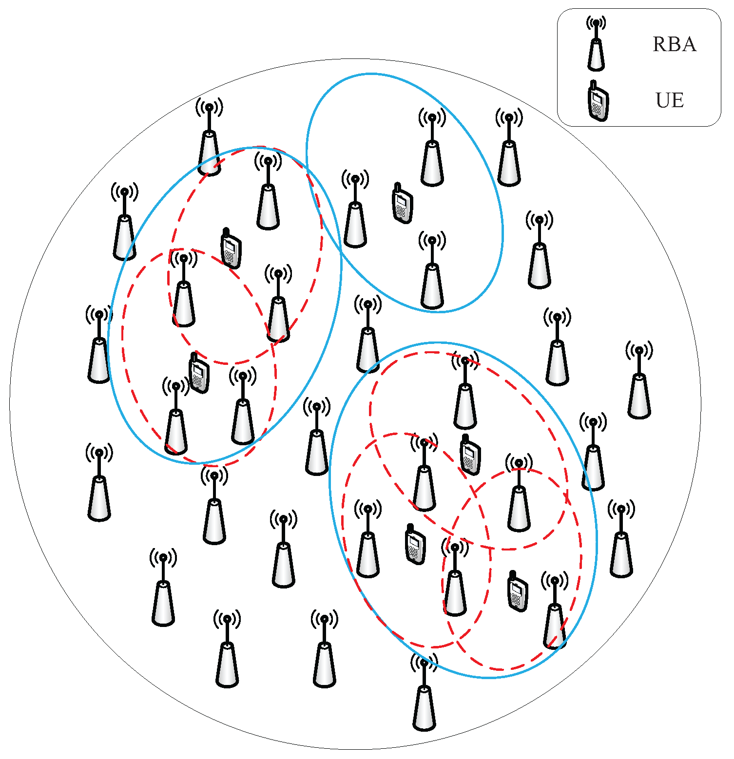
The remainder of the paper is organized as follows. In Section 2, the system model is introduced. Section 3 describes details about the virtual cell merging scheme based on the interference graph and applies different precoding schemes, such as ZF, MVC-MMSE and IA, to the merged virtual cell clusters. Simulation results of average user spectral efficiency are presented with different transmission schemes in Section 4, and Section 5 concludes this paper.
Notation: We use lowercase and uppercase boldface letters for column vectors and matrices, respectively; ( · ) T , ( · ) H and ( · ) 1 for the transpose, conjugate transpose and inversion of a matrix, respectively. A i , j denotes the entry in the i-th row and j-th column of matrix A . The N × N identity matrix is denoted by I N . E ( · ) denotes the expectation of a random variable. ⊙ denotes the Hadamard product. eigvec ( · ) denotes the eigenvector of the matrix. · denotes the norm of the matrix.

2. System Model

We consider a circular area A where B RBAs and K single antenna users (multi-antenna users can be easily obtained from the model extended from the single-antenna user, where the single-antenna users can be seen as multiple streams of multi-antenna users) are uniformly and randomly distributed. Without loss of generality, we normalize the radius of A to one. Denote the set of RBAs and the set of users in the UDN as B and K , with B = B and K = K , respectively. Assume that each of the RBAs is equipped with a single antenna, and all of the RBAs are connected to a central processor where the next generation fronthaul interface (NGFI) [19] is used to support necessary CSI and control signaling exchange. For any user k ( k K ) in the UDN, he or she preliminarily selects N 0 closest RBAs to form his or her virtual cell, which is the initial serving RBA set of user k, denoted as V k . If there is no virtual cell merging, MRT is adopted in each of the K virtual cells according to [11], regardless of ICI. The details of virtual cell merging are discussed in Section 2. Assume that after virtual cell merging, there exist M merged virtual cell clusters. Denote the user set and RBA set of the m-th ( 1 m M ) merged virtual cell cluster as K m and B m , with K m = K m and B m = N m , respectively. All of the users in K m are jointly served by all of the RBAs in B m , as depicted in Figure 1. We focus on a specific user k K m . Then, the channel vector from merged virtual cell cluster m to user k can be modeled as:
h k , B m = λ k , B m g k , B m
where λ k , B m C 1 × N m is the large scale fadings from the merged virtual cell cluster m to user k. λ k , B m includes path loss and shadowing, which change in a relatively slow manner and can be estimated accurately via long-term statistics. g k , B m C 1 × N m represents the small-scale fadings from all of the RBAs in B m to user k and are assumed to be independently and identically drawn from a unit zero-mean circularly-symmetric complex Gaussian distribution.
Denoting the transmitted signal vector form the merged virtual cell cluster m to its user k as x k , B m C N m × 1 , the received signal vector at user k can then be modeled as:
y k = l = 1 M j K l p j h k , B l x j , B l + n k = p k h k , B m x k , B m + j K m , j k p j h k , B m x j , B m + l = 1 , l m M j K l p j h k , B l x j , B l + n k
where n k CN ( 0 , σ 2 ) is the additive white Gaussian noise (AWGN) observed by user k, and p j is the transmitting power of user j, which is assumed to be the same for any different users in this paper, i.e., p j P , j K . The first term on the right-hand side of the second equal sign in (2) is the useful signal received by user k, while the second term and the third term denote the intra-cluster interference caused by other users in the m-th merged virtual cell cluster and inter-cluster interference caused by users in other merged virtual cell clusters, respectively. Without loss of generality, we assume the transmitted signal vector x k , B m to be the precoded symbols of user k, which can be written as:
x k , B m = w k , B m s k
where w k , B m C N m × 1 is the precoding vector of user k, and s k is the information symbol of user k with zero mean and unit variance. Information symbols are assumed to be independent and uncorrelated between different users. To meet the equal total transmitting power constraint of each user, we have w k , B m H w k , B m = 1 . Substituting (3) into (2), we can write the received useful signal power and interference power as (4) and (5), respectively.
S k = P h k , B m w k , B m w k , B m H h k , B m H
I k = j K m , j k P h k , B m w j , B m w j , B m H h k , B m H + l = 1 , l m M j K l P h k , B l w j , B l w j , B l H h k , B l H
In a typical UDN, it is often the case that there are a large number of interfering users. Therefore, the interference received by user k can be well approximated as a zero mean complex Gaussian random variable with variance I k . As a result, the ergodic spectral efficiency of user k can be then expressed as (6), according to Shannon Equation [20],
R k = E H K m , B m 1 + S k I k + σ 2
where the expectation is taken over the channel matrix between user set K m and its serving RBAs set B m .

3. Transmission Schemes Based on Virtual Cell Merging

Since no cooperation among the initial virtual cells will introduce strong ICI, it is natural to let the virtual cells with distinct ICI jointly serve their users in light of coordinated multi-point (CoMP) transmission. This motivates the idea of virtual cell merging. An intuitive solution is to group the initial virtual cells that overlap each other together as done in [11]. However, it is not easy to control the size of the merged virtual cell clusters due to the random network topology; hence, the signal processing complexity is not predictable. Instead, this section proposed an interference graph-based virtual cell merging scheme, where the size of the merged virtual cells can be well scaled by tuning the interference graph threshold. According to information theory [21], linear precoding, such as ZF and MVC-MMSE, can obviously eliminate the intra-cluster and inter-cluster interference with a much lower complexity. Therefore, we consider ZF and MMSE based on the low complexity virtual cell merging to eliminate the strong interference.

3.1. Virtual Cell Merging with ZF and MVC-MMSE Transmission

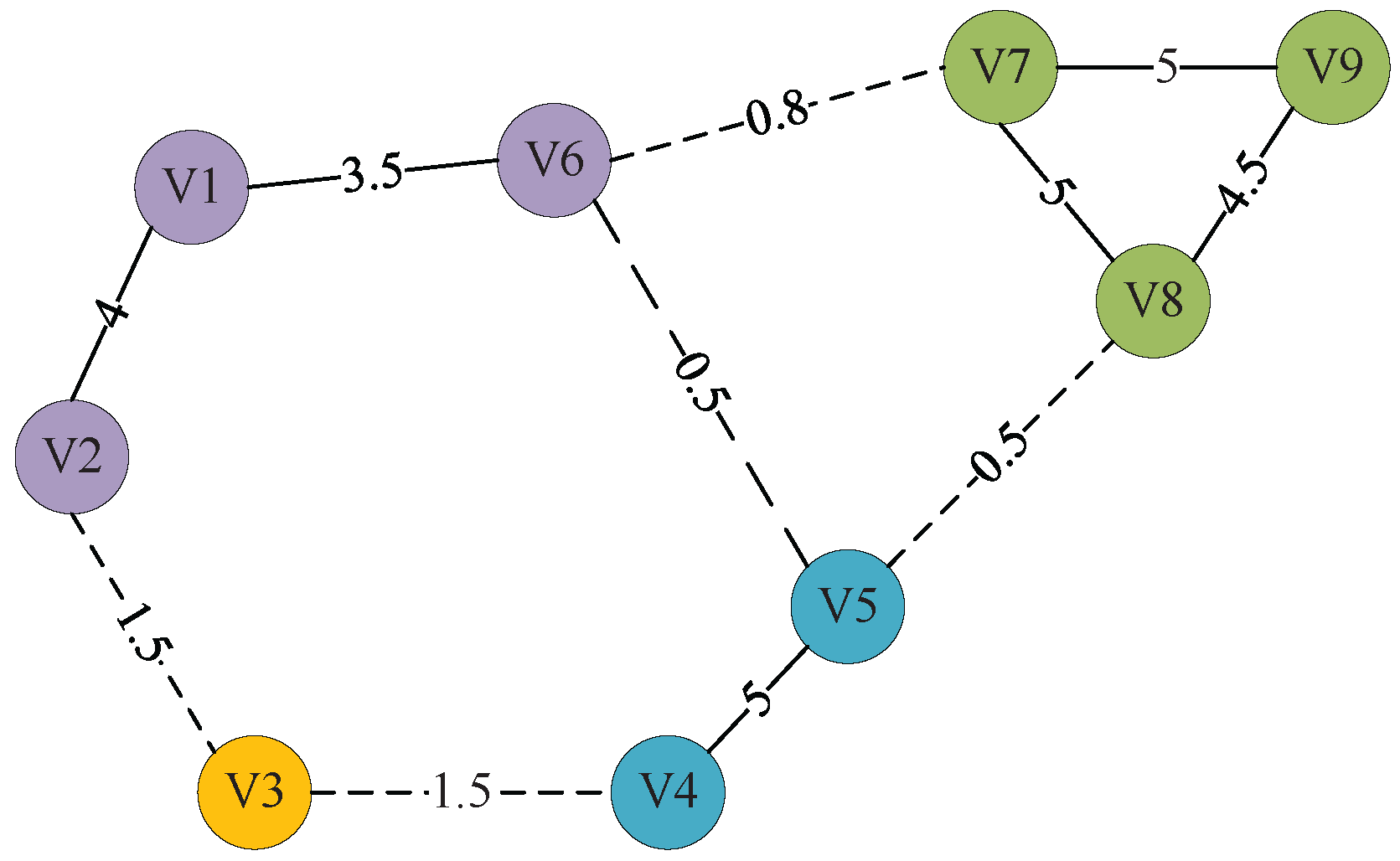
3.1.1. Interference Graph Construction

With each user’s information symbol transmitted by equal power, the ergodic interference from an RBA to a user can be measured by the large-scale fading coefficient between them. Based on this observation, we propose an intuitive metric to describe the potential interference strength between two different virtual cells, which can be formulated as:
γ j , k = γ k , j = + for   k = j λ j , V k λ j , V j + λ k , V j λ k , V k otherwise
where γ j , k is the potential interference strength between initial virtual cells of user k and user j and λ k , V j is the large-scale fading vector from user j’s initial virtual cell to user k. Generally, larger γ j , k indicates more severe interference. We model each user’s initial virtual cell as a vertex in an undirected graph G where the edges are weighted by the potential interference strength between the vertexes. To determine whether two virtual cells belong to the same cluster, an interference strength threshold g t h is introduced. Based on G and g t h , we generate a binary graph G b , which can be described by a K by K binary matrix T . We have:
T k , j = 1 for   γ k , j g t h 0 otherwise
this implies that the vertexes corresponding to the initial virtual cells of user k and user j are connected in G b if and only if the interference strength exceeds the given threshold. Note that the infinite value of γ k , k ensures that the initial virtual cell of user k is always self-connected.

3.1.2. Virtual Cell Merging Based on the Interference Graph

With g t h appropriately selected, it is reasonable to consider that the initial virtual cells corresponding to the connected vertexes in G b have strong interference with each other. Therefore, for the sake of ICI mitigation, it is intuitive to group the initial virtual cells that connect to each other into one coordinating cluster. This directly leads to our virtual cell merging algorithm, where initial virtual cells represented by the vertexes within the same MCC of G b merge into one virtual cell cluster. Details of the virtual cell merging algorithm are presented in Algorithm 1. Figure 2 is an illustration of the interference graph-based virtual cell merging process. In this illustration, there are nine initial virtual cells, denoted by V 1 , , V 9 in the circles in Figure 2. Herein, g t h is set to two, hence the edges with weights larger than two are considered to be connected, denoted by the solid lines. The dashed edges or the edges that have not been drawn all have a weight of less than two and are considered to be disconnected. It easy to get the MCCs of the graph according to Algorithm 1. We have four MCCs in this illustration, indicating that four virtual cell clusters are finally formed, where all of the RBAs of each cluster jointly serve the users therein.
Algorithm 1 Interference graph-based virtual cell merging algorithm.
Initialization:
  • Each user k K selects N 0 closest RBAs to form his or her virtual cell V k ; interference graph G is constructed according to (7). Given g t h , the binary graph G b is generated according to (8), as well as its describing matrix T . Set the initial merged virtual cell cluster index as m = 1 .
  • while K do
    • ∀ user k K , initialize the user set as K = k and the RBA set as B m = V k .
    • Remove user k from the unmerged user set: K = K \ K m .
    • Generate the connected user set with K m as C m = { j K | T K m , j 0 } .
    • while C m do
      •  Update the current user set K m = K m C m .
      •  Update the current RBA set B m = B m V C m .
      •  Update the unmerged user set K = K \ C m .
      •  Recalculate the connected user set with K m as C m = { j K | T K m , j 0 } .
    • end while
    • m = m + 1 .
  • end while
    return K j and B j , ( 1 j m 1 )

3.1.3. ZF Transmission

We consider using ZF to eliminate intra-cluster interference, where only intra-cluster CSI is required. For each merged virtual cell cluster B m and the user group K m it serves, the downlink channel matrix can be denoted as H K m , B m C K m × B m . Then, the ZF precoding matrix Z K m , B m can be calculated as the pseudo-inverse of H K m , B m , i.e., Z K m , B m = H K m , B m H H K m , B m H K m , B m H 1 . Nevertheless, the existence of Z K m , B m requires H K m , B m to have full row rank, where B m K m must be ensured. Neither the virtual cell grouping method based on cell overlapping nor the virtual cell merging scheme based on interference graph can guarantee such a full row rank condition. As a result, MRT is still adopted in this circumstance, and the corresponding precoding matrix is denoted as R K m , B m = H K m , B m H . Considering the constraint that each user’s precoding vector has unit norm, the precoding vector for user k K m under the ZF transmission scheme can be expressed as:
w k , B m ZF = z k , B m / z k , B m if   B m K m r k , B m / r k , B m otherwise
where z k , B m and r k , B m are the column vectors of Z K m , B m and R K m , B m corresponding to user k in K m , respectively.

3.1.4. MVC-MMSE Transmission

Note that the ZF transmission scheme can only eliminate the intra-cluster interference. As far as a practical UDN scenario is considered, it is often the case that multiple virtual cell clusters coexist. The consequent inter-cluster interference may also affect the system performance prominently. In order to further mitigate the inter-cluster interference, an MVC-MMSE precoding scheme is proposed, where not only intra-cluster CSI, but also inter-cluster CSI are required. This indicates that there are CSI exchange between virtual cell clusters, which contribute to the signaling overhead. However, it is still much milder than the fronthaul compared to the global optimum scheme, where user data exchange is required among clusters. For any user group K m , the MVC-MMSE precoding matrix M K m , B m can be obtained by solving the following optimization problem:
M K m , B m = argmin { G } E ( H K m , B m G s K m + n K m s K m 2 + l = 1 , l l M H K l , B m G s K m 2
where H K l , B m C K l × B m is the downlink channel matrix between the RBAs in the m-th cluster and the users in the l-th cluster, G is the objective variable, s K m C K m × 1 is the information symbol vector transmitted for the users in the m-th cluster and n K m C K m × 1 is the AWGN whose entries are independently and identically drawn from CN ( 0 , σ 2 ) . The objective function in (10) is to jointly minimize the signal receiving error in the m-th cluster and the amount of interference it pours into the other clusters. With a constrained total transmission power, the solution of (10) is given as follows.
Firstly, simplify the objective function in (10) as:
J ( G ) = E ( H K m , B m G I K m ) s K m 2 + l = 1 , l m M H K l , B m G s K m 2 + σ 2 K m = tr E ( H K m , B m G I K m ) H ( H K m , B m G I K m ) + l = 1 , l m M G H H K l , B m H H K l , B m G + σ 2 K m = tr G H H K m , B m H H K m , B m G G H H K m , B m H H K m , B m G + l = 1 , l m M G H H K l , B m H H K l , B m G + σ 2 K m = tr G H H K m , B m H H K m , B m + l = 1 , l m M H K l , B m H H K l , B m G G H H K m , B m H H K m , B m G + σ 2 K m
Then, we can solve the optimization problem in (11) with the Lagrange multiplier method. Let:
L ( G , λ ) = J ( G ) + λ ( tr G H G 1 )
R = H K m , B m H H K m , B m + l = 1 , l m M H K l , B m H H K l , B m + λ I K m
Then, define matrix U and V based on R as:
U = R 1 2 G V = R 1 2 H K m , B m H
rewrite (12) as the following quadratic form:
L ( G , λ ) = U V 2 tr H K m , B m R 1 H K m , B m H + σ 2 K m λ
From (15), we know that Equation (12) can be minimized only if U = V . Therefore, we can get that the optimal multi-cell precoding vector is:
G opt = R 1 H K m , B m H = l = 1 M H K l , B m H H K l , B m + λ I K l 1 H K m , B m H
We can get the boundary condition λ = σ 2 by letting L ( G , λ ) λ = 0 in (12). Therefore, (16) can be transformed into (10).
Normalizing the columns of M K m , B m , we can get the precoding vector for each user k in K m under the MVC-MMSE transmission scheme:
w k , B m MVC MMSE = m k , B m m k , B m
where m k , B m is the column vector of M K m , B m corresponding to user k in K m .

3.2. Virtual Cell Merging with IA Transmission

The achievable rate is influenced mainly by the strong interference and is quite insensitive to the weak interference. Therefore, eliminating very weak interference hardly improves the achievable rate, but requires additional signal dimensions. In addition, eliminating very weak interference may even degrade the performance because the power of the desired signal cannot be collected in the signal space used to cancel interference. IA is a well-known signal processing approach that attempts to simultaneously align the interference on a lower dimensional subspace at each receiver, so that the desired signals can be transmitted on the interference-free dimensions. Intuitively, we can consider IA within every cluster, which has very strong intra-cluster interference. Herein, we improve our virtual cell merging algorithm with the three strongest interference strengths in order to adapt the IA algorithm.

3.2.1. Virtual Cell Merging

Assume that γ k , K \ k denotes user k’s interference strength list. Find user k and user j that have the strongest interference with each other as:
k , j = { k , j max ( γ k , j ) }
Then, find the third user q that has the strongest interference with user k and user j as
q = { q max ( γ k , q + γ j , q ) }
Then, a virtual cell cluster is formed with the three strongest interfering virtual cells, where the user set is denoted as K m = { j , k , q } and the RBA set is denoted as B m = V k V j V q . Update the ungrouped user set and RBA set as K = K \ K m and B = B \ B m , respectively, and repeat the above steps until K is empty. The details of this virtual cell merging algorithm are presented in Algorithm 2.
Algorithm 2 Virtual cell merging algorithm.
Initialization:
  • Each user k K selects N 0 closest RBAs to form his or her virtual cell V k ; interference graph G is constructed according to (7). Set the initial merged virtual cell cluster index as m = 1 .
  • while K do
    • Find user k and user j: k , j = { k , j max ( γ k , j ) }
    • Find the third user q: q = { q max ( γ k , q + γ j , q ) }
    • Update user set K m = { j , k , q } , K = K \ K m
    • Update RBA set B m = V k V j V q , B = B \ B m
    • m = m + 1 .
  • end while
  • M = m 1 .
  • return K i and B i , ( 1 i M )

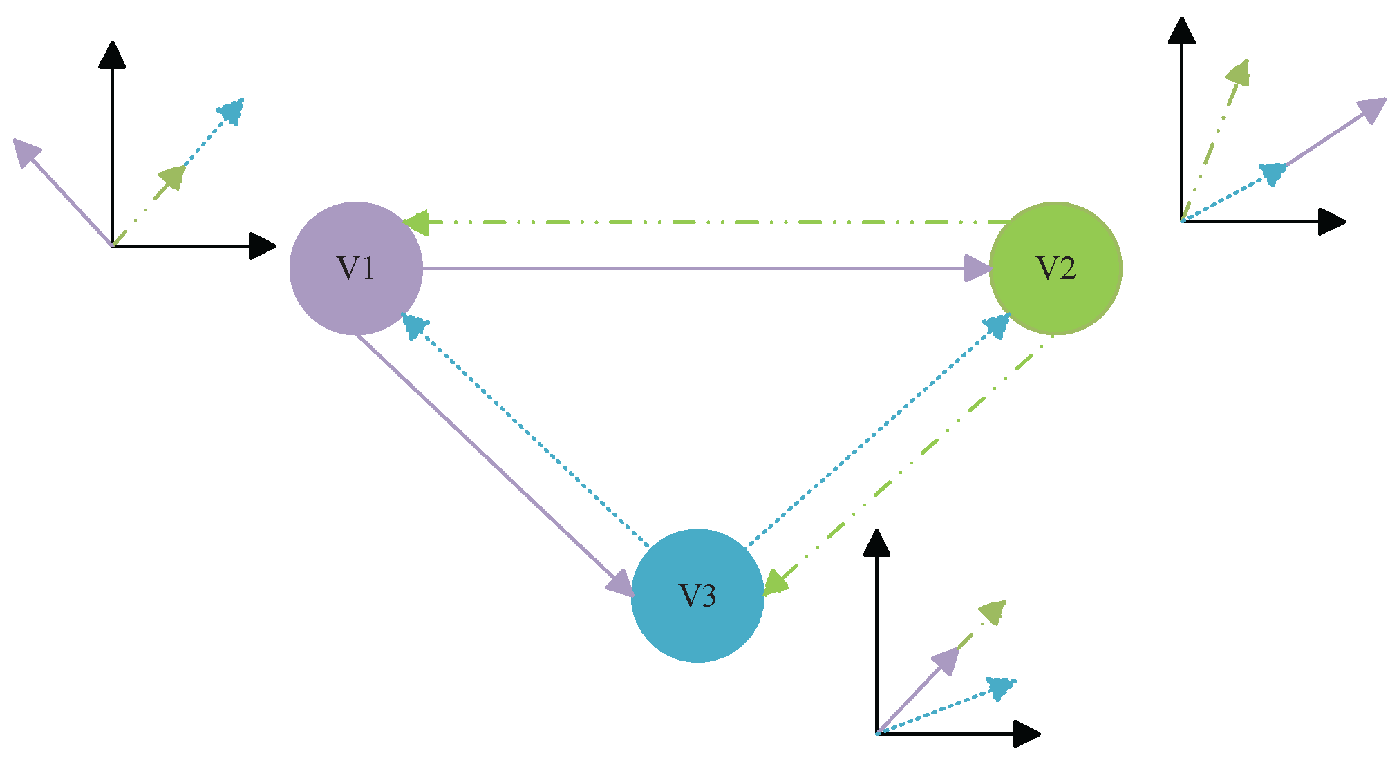
3.2.2. IA Transmission

After virtual cell merging, we consider IA within every cluster to eliminate strong interference. We first consider IA with one cluster consisting of three virtual cells that have the strongest interference strength with each other. Figure 3 illustrates the procedure used for designing the transmit beamforming matrices for the clusters. As shown in Figure 3, the interference can be aligned on a lower dimensional subspace at each receiver, then the desired signals can be transmitted on the interference-free dimensions by IA. We assume that perfect channel state information is available to both the transmitter and receiver. There are three virtual cells (i.e., V1, V2 and V3), and the corresponding users are user1 , user2 and user3 in the cluster.
Assume that each user is equipped with D antennas, D = N 0 . Consider the interference from V1, V2 to user3; the following conditions are obtained:
span ( H 3 , 1 W 1 ) = span ( H 3 , 2 W 2 )
where span ( · ) denotes the subspace spanned by the column vectors of a matrix, H i , j C N 0 × D is the channel matrix from the j t h RBA to the i t h user, which are all equipped with multi-antennas, W 1 and W 3 denote the transmit beamforming matrix for V1 and V3, respectively. What is more, the first h k , B m in the system model is a sector, because users are equipped with a single antenna. Multi-antenna users can be easily obtained from the model extended from the single-antenna user, where the single-antenna users can be seen as multiple streams of multi-antenna users. Therefore, in the IA transmission, we use H i , j as a matrix, where users and RBAs are all equipped with multi-antennas.
Then, consider the interference to user1 and user2 from other two virtual cells as:
span ( H 2 , 1 W 1 ) = span ( H 2 , 3 W 3 )
span ( H 1 , 3 W 3 ) = span ( H 1 , 2 W 2 )
From (21) and (22), we can get:
span ( W 1 ) = span ( H 2 , 1 1 H 2 , 3 W 3 )
span ( W 2 ) = span ( H 1 , 2 1 H 1 , 3 W 3 )
Using (20), (23) and (24), we can obtain the transmit beamforming matrices of W 3 as follows:
w 3 i = eigvec ( H 2 , 3 1 H 2 , 1 H 3 , 1 1 H 3 , 2 H 1 , 2 1 H 1 , 3 )
where i = { 1 , 2 , , N 0 / 2 } denotes different data streams. Then, W 3 can be expressed as arbitrary N 0 / 2 eigenvectors of matrix H 2 , 3 1 H 2 , 1 H 3 , 1 1 H 3 , 2 H 1 , 2 1 H 1 , 3 . After the normalization, we can get:
w 3 i = eigvec ( H 2 , 3 1 H 2 , 1 H 3 , 1 1 H 3 , 2 H 1 , 2 1 H 1 , 3 ) H 2 , 3 1 H 2 , 1 H 3 , 1 1 H 3 , 2 H 1 , 2 1 H 1 , 3
w 1 i = eigvec ( H 2 , 1 1 H 2 , 3 w 3 i ) H 2 , 1 1 H 2 , 3 w 3 i
w 2 i = eigvec ( H 1 , 2 1 H 1 , 3 w 3 i ) H 1 , 2 1 H 1 , 3 w 3 i
After determining the transmit beamforming matrices of W 1 , W 2 and W 3 , we can design the receive beamforming matrices U k for all users in order to cancel out the interference signals from the other virtual cells. With the decision variables U k , an optimization problem can be formulated as minimizing the mean square error as:
L M S E = k = 1 K E U k H y k s k F 2 = k = 1 K E U k H ( p k H k , k W k s k + p i i = 1 , i k K H k , i W i s i + n k ) s k 2
We can get the normalized U k by letting L M S E U k = 0 , then:
U k = l = 1 K ( H k , l W l W l H H k , l H ) + σ 2 I N 1 H k , k W k l = 1 K ( H k , l W l W l H H k , l H ) + σ 2 I N 1 H k , k W k

4. Simulation Results and Analysis

A circular area A with unit radius is considered in the simulation, within which K = 50 users are uniformly and independently distributed. There are B (B may take the value of 1000 and 10,000, making the network ultra dense) RBAs uniformly and independently distributed across A . Here, we take the value of B = 1000 and K = 50 directly from [11] for the sake of comparison. However, it is pointed out in [7] that the number of BSs in the UDN is likely to be significantly more than the number of User equipments (UEs). Hence, we make an even more aggressive assumption that B = 10,000 in this part to catch a glimpse of the performance of the proposed schemes in a network that is really “ultra dense”. Then, the network density can be described as the ratio of the number of RBAs and the number of users ρ = B K . The path loss between any user k K and any RBA b B is modeled as λ k , b = d k , b μ / 2 , where d k , b is the distance between user k and RBA b, the minimum of which is set to be 0.1; μ = 4 is the path-loss exponent factor. In fact, large-scale fading is equal to the product of shadowing fading and path loss. If shadowing fading is considered in this system model, it may be equivalent to the distance in path loss calculation being different. In this paper, we used Monte Carlo simulation in the simulation process; the number of simulations is quite large, including almost all kinds of distances; so here, we can ignore the shadowing fading. This paper aims to handle the intricate interference in UDN, so an interference limited scenario is considered, where P / σ 2 is set to 10 dB. The simulation parameters are listed in Table 1.
We focus on the performance of average user spectral efficiency, which can be formulated as R ¯ = 1 K k K R k . We now demonstrate the advantages of the proposed transmission schemes based on different virtual cell merging schemes, in terms of average user spectral efficiency and the corresponding signal processing embodied by the average cluster size.

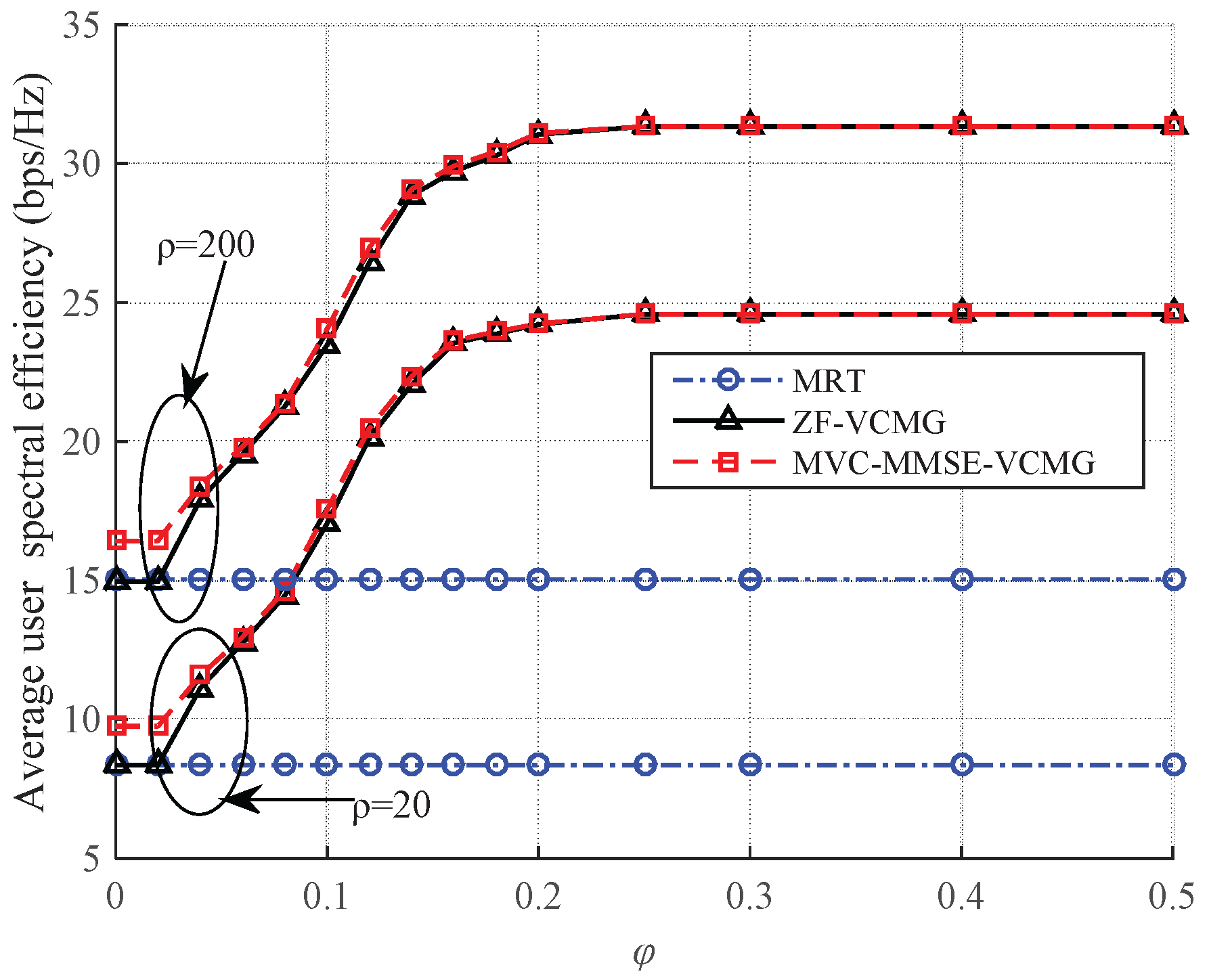
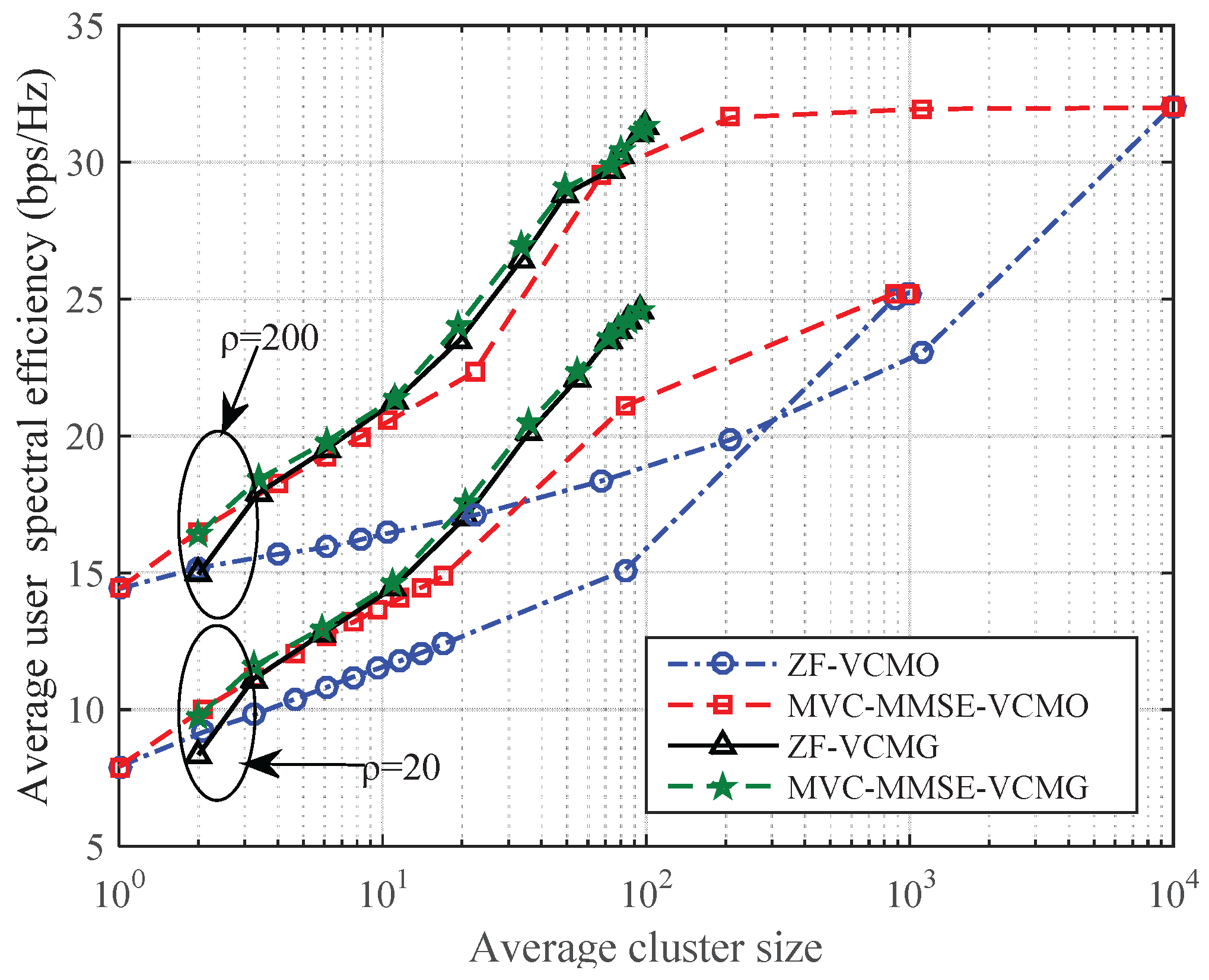
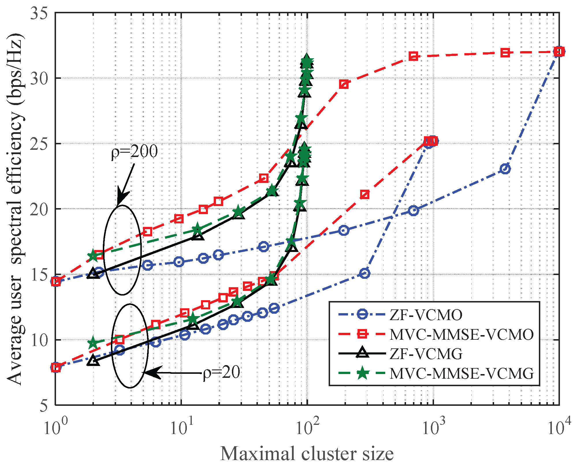
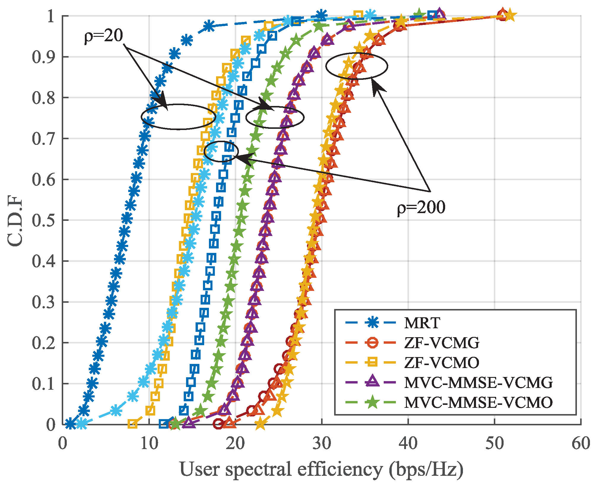
4.1. Virtual Cell Merging with ZF and MVC-MMSE Transmission

Let w k , B m denote any precoding vector of any user k K m , i.e., w k , B m may be any one of w k , B m ZF and w k , B m MVC MMSE .
Five different transmission schemes are simulated in this paper, including MRT, ZF with virtual cell merging based on virtual cell overlapping (ZF-VCMO) [11], ZF with virtual cell merging based on the interference graph (ZF-VCMG), MVC-MMSE with virtual cell merging based on virtual cell overlapping (MVC-MMSE-VCMO) and MVC-MMSE with virtual cell merging based on the interference graph (MVC-MMSE-VCMG).
Figure 4 compares the average user spectral efficiency R ¯ of MRT, ZF-VCMO and MVC-MMSE-VCMO at different initial virtual cell sizes. It can be seen clearly that different from the no virtual cell merging case (MRT) where the highest R ¯ is achieved when the initial virtual cell size N 0 is small, the ZF-VCMO scheme can markedly improve R ¯ as the increase of N 0 . When N 0 is large enough, R ¯ becomes saturated. This is because by including more RBAs into each user’s initial virtual cell, more users would overlap with each other. It is inevitable that all of the users and RBAs would be grouped together at some N 0 , after which no more increase of R ¯ is observed. We can also draw the conclusion from Figure 4 that MVC-MMSE-VCMO can significantly improve R ¯ at the same N 0 compared with ZF-VCMO. As a result, MVC-MMSE-VCMO can reach a targeted R ¯ at a much smaller N 0 , hence at a much smaller merged virtual cell cluster size, although inter-cluster CSI exchange is required. This implies that MVC-MMSE-VCMO can significantly reduce the signal processing complexity, which scales with the sizes of the merged virtual cell clusters, at the price of heavier signaling overhead.
Figure 5 compares R ¯ of MRT, ZF-VCMG and MVC-MMSE-VCMG at different relative interference graph thresholds φ, which is defined as φ = g t h min γ k , j / max γ k , j min γ k , j . Intuitively, φ represents the connection degree of G b . By tuning φ, we can easily control the size of merged virtual cell clusters. For ZF-VCMG and MVC-MMSE-VCMG, the initial virtual cell size N 0 is set to be two; that is to say, every user primarily selects two nearest RBAs to form its initial virtual cell before virtual cell merging is performed. It can be seen clearly that ZF-VCMG can achieve significantly higher R ¯ than MRT at different φ. When φ is large enough, R ¯ also becomes saturated. This is because when G b is dense enough, there would be only one MCC, resulting in a single merged virtual cell cluster, containing all of the initial virtual cells. Different from the case in Figure 4, MVC-MMSE-VCMG only shows a marginal performance increase compared to ZF-VCMG. This implies that the virtual cell merging based on the interference graph can effectively avoid major interference in UDN without inter-cluster CSI exchange.
Since both VCMO and VCMG can significantly improve R ¯ , both at the price of the increase of signal processing complexity or signaling overhead, Figure 6 and Figure 7 show the average cluster size and maximal cluster size of these transmission schemes respectively, when different R ¯ are reached. It should be noted that with the given ρ, the signaling overhead required for MVC-MMSE scales linearly with the average cluster size, while the signal processing complexity required for ZF or MVC-MMSE scales linearly with the cube of the maximal cluster size. It can be clearly seen that the ZF-VCMG scales much better than ZF-VCMO in terms of both average and maximal cluster size. ZF-VCMG can attain almost the same maximal cluster size as MVC-MMSE-VCMO when the targeted R ¯ is low and can further achieve higher R ¯ at a much smaller maximal cluster size than ZF-VCMO and MVC-MMSE-VCMO. This indicates that ZF-VCMO can achieve a targeted R ¯ with much lower signal processing complexity while no inter-cluster CSI exchange is needed. One may argue that the curves for ZF-VCMG and MVC-MMSE-VCMG become more and more steep with the increase of the maximal cluster size in Figure 7. This brings a very sharp increase of average user spectral efficiency when the maximal cluster size is around 100. In fact, the maximal cluster size is upper bounded by K × N 0 , which corresponds to the situation that all users’ initial virtual cells merge into one cluster. With the increase of φ, the average cluster size grows; so does the maximal cluster size, but it cannot exceed K × N 0 , which is the upper bound. When the maximal cluster size is close to the upper bound, a marginal further increase of the maximal cluster size may bring remarkable growth in the average cluster size, so we can still see a significant increase of the average user spectral efficiency. This leads to a large slope of the corresponding curves around the upper bound. However, the average user spectral efficiency will not increase infinitely due to the limited number of transmitting antennas. As a result, the average and maximal cluster size of ZF-VCMG and MVC-MMSE-VCMG can be well controlled by N 0 and φ, while that of ZF-VCMO and MVC-MMSE-VCMO is totally out of control, especially when the network is ultra dense.
Figure 8 presents the cumulative distribution function (CDF) of R ¯ for different transmission schemes. It can be clearly seen that R ¯ of the VCMO- and VCMG-based transmission schemes are distributed in a much smaller range than MRT, indicating that the user-centric virtual cell can effectively eliminate the cell edge in the UDN, thus greatly reducing the performance difference among the users. As a result, the user spectral efficiency performance is much less sensitive to the users’ positions than the BS-centric scheme is, stepping towards the goal of consistent high quality of experience (QoE) in UDN. We can also observe that ZF-VCMG outperforms MRT and ZF-VCMO significantly in terms of both average user spectral efficiency and edge user spectral efficiency. MVC-MMSE-VCMO can attain the performance of ZF-VCMG if B is large enough, but inter-cluster CSI exchange is required. MVC-MMSE-VCMG almost makes no contribution to the right shift of the CDF curves, although additional inter-cluster CSI exchange is provided.

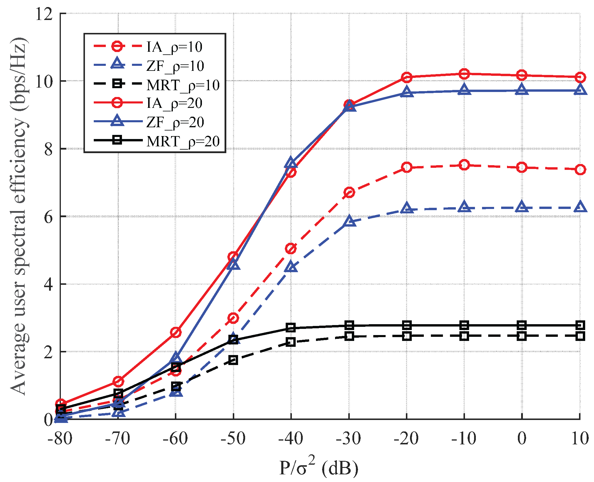
4.2. Virtual Cell Merging with IA Transmission

In this section, the proposed IA algorithm based on the virtual cell-cluster is evaluated in terms of the average user spectral efficiency by simulations, as well as ZF and MRT.
Figure 9 shows the average user spectral efficiency versus P / σ 2 under different transmission schemes, such as ZF and MRT precoding with K = 51 , ρ = 10 , ρ = 20 and the user antenna number D = N 0 = 2 . With the proposed virtual cell merging scheme, where every three initial virtual cells form a virtual cell-cluster, the number of virtual cell clusters is 17. It is obvious that the average user spectral efficiency of the system increases with the increase of P / σ 2 for all of the transmission schemes. Additionally, our proposed IA scheme based on low complexity virtual cell merging can reach higher average user spectral efficiency than ZF and MRT under different network densities, thus under different P / σ 2 . Besides, the interference from the data streams of other users increases with users antenna number. Nevertheless, we can eliminate these interferences by a global ZF, taking all of the data streams of all users into consideration. This requires us to know the global channel state information (CSI), and the information-bearing symbols of all of the users’ data streams should be ready at all RBAs, since it is a global cooperative transmission. This would bring heavy burden to the fronthaul in UDN. Besides, the signal processing complexity could be prohibitively high if the number of RBAs is large enough. In the proposed IA scheme, which is a partial cooperative transmission, only intra-cluster CSI exchange and user data sharing are required. Therefore, it can scale well with the network size. Therefore, all of the transmission schemes are simulated in a partial cooperation or no cooperation regime, so that the corresponding signal processing complexities and signaling overheads are comparable. It can be seen clearly from Figure 9 that the proposed low complexity virtual cell merging based on IA can greatly outperform ZF and MRT in terms of the average user spectral efficiency.

5. Conclusions

This paper aims to mitigate the large and complex interference in downlink UDN. Different from the traditional BS-centric cellular approach and the complex and time-consuming global optimal solution, a user-centric virtual cell paradigm is adopted. An interference graph-based virtual cell merging scheme is proposed in comparison with the overlapping-based virtual cell merging approach. After the interference graph is created, RBAs and users in the virtual cells within the same maximal connected component are grouped together and merged into one new virtual cell cluster, where users are jointly served via ZF. MVC-MMSE-based transmission schemes are further proposed to enhance the performance of the two virtual cell merging methods, which is shown to be effective for VCMO. Additionally, the interference alignment algorithm is proposed based on the improved virtual cell merging to eliminate the strong interference between different virtual cells. Simulation results show that the proposed ZF-VCMG and MVC-MMSE-VCMO can attain the average user spectral efficiency performance of ZF-VCMO with a much smaller virtual cell cluster size and significantly reduced signal processing complexity. Besides, the proposed user-centric transmission schemes greatly outperform the BS-centric transmission scheme (MRT) in terms of both the average user spectral efficiency and edge user spectral efficiency. What is more, IA based on the low complexity virtual cell merging can achieve much better performance than ZF and MRT precoding in terms of average user spectral efficiency. With the increased number of P / σ 2 and ρ, IA leads to more improvement and low complexity in average user spectral efficiency gain, compared to ZF and MRT. This indicates that the proposed scheme scales much better with the network density than ZF and MRT without merging, revealing that it can be applied suitably in ultra dense networks. Additionally, this paper treats all of the users equally without differentiating them based on the channels. Therefore, the precoding performance could be further improved by applying appropriate power control or IA algorithms.

Acknowledgments

This work was supported by China’s 863 Project (No. 2015AA01A706), the National Science and Technology Major Project (No. 2016ZX03001017), Science and Technology Program of Beijing (D161100001016002), the Scientific and Technological Cooperation Projects (No. 2015DFT10160B) and by the State Key Laboratory of Wireless Mobile Communications, Samsung, and China Academy of Telecommunications Technology (CATT).

Author Contributions

The work presented in this paper corresponds to a collaborative development by all authors. Xin Su and Lianfen Huang defined the research line. Xiaopeng Zhu and Chiyang Xiao developed the proposed algorithm and wrote the paper. Jie Zeng gave many modification suggestions about the paper. All authors have read and approved the final manuscript.

Conflicts of Interest

The authors declare no conflict of interest.

References

  1. Cisco Visual Networking Index: Global Mobile Data Traffic Forecast Update, 2015–2020, Cisco White Paper. 2016. Available online: http://www.cisco.com/c/en/us/solutions/collateral/service-provider/visual-networking-index-vni/mobile-white-paper-c11-520862.html (accessed on 17 October 2016).
  2. Hwang, I.; Song, B.; Soliman, S. A Holistic View on Hyper-Dense Heterogeneous and Small Cell Networks. IEEE Commun. Mag. 2013, 51, 20–27. [Google Scholar] [CrossRef]
  3. Chih-Lin, I.; Han, S.; Xu, Z.; Sun, Q.; Pan, Z. G: Rethink Mobile Communications for 2020+. Phil. Trans. R. Soc. 2016, 374. [Google Scholar] [CrossRef] [PubMed]
  4. Larsson, E.G.; Edfors, O.; Tufvesson, F.; Marzetta, T.L. Massive mimo for next generation wireless systems. IEEE Commun. Mag. 2014, 52, 186–195. [Google Scholar] [CrossRef]
  5. Nikopour, H.; Yi, E.; Bayesteh, A.; Au, K.; Hawryluck, M.; Baligh, H.; Ma, J. SCMA for downlink multiple access of 5G wireless networks. In Proceedings of the IEEE GLOBECOM, Austin, TX, USA, 8–12 December 2014; pp. 3940–3945.
  6. Galinina, O.; Pyattaev, A.; Andreevy, S.; Dohler, M.; Koucheryavy, Y. 5G multi-RAT LTE-WiFi ultra-dense small cells: Performance dynamics, architecture, and trends. IEEE J. Sel. Areas Commun. 2015, 33, 1224–1240. [Google Scholar] [CrossRef]
  7. Lo´pez-Pe´rez, D.; Ding, M.; Claussen, H.; Jafari, A. Towards 1 Gbps/UE in Cellular Systems: Understanding Ultra-Dense Small Cell Deployments. IEEE Commun. Surv. Tutor. J. 2015, 17, 2078–2101. [Google Scholar] [CrossRef]
  8. Heath, R.; Peters, S.; Wang, Y.; Zhang, J. A current perspective on distributed antenna systems for the downlink of cellular systems. IEEE Commun. Mag. 2013, 51, 161–167. [Google Scholar] [CrossRef]
  9. Wang, J.; Dai, L. Asymptotic Rate Analysis of Downlink Multi-user Systems with Co-located and Distributed Antennas. IEEE Trans. Wirel. Commun. 2015, 14, 3046–3058. [Google Scholar] [CrossRef]
  10. Dai, L. An uplink capacity analysis of the distributed antenna system (DAS): From cellular DAS to DAS with virtual cells. IEEE Trans. Wirel. Commun. 2014, 13, 2717–2731. [Google Scholar]
  11. Wang, J.; Dai, L. Downlink Rate Analysis for Virtual-Cell based Large-Scale Distributed Antenna Systems. IEEE Trans. Wirel. Commun. 2016, 15, 1998–2011. [Google Scholar] [CrossRef]
  12. Gao, H.; Lv, T.; Fang, D.; Yang, S.; Yuen, C. Limited feedback-based interference alignment for interfering multi-access channels. IEEE Commun. Lett. 2014, 18, 540–543. [Google Scholar] [CrossRef]
  13. Gao, H.; Leithon, J.; Yuen, C.; Suraweera, H. New uplink opportunistic interference alignment: An active alignment approach. In Proceedings of the IEEE WCNC, Shanghai, China, 7–10 April 2013; pp. 1123–1127.
  14. Zhou, R.; Lv, T.; Long, W.; Gao, H. Limited feedback schemes based on inter-cell interference alignment in two-cell interfering MIMO MAC. In Proceedings of the IEEE ICC, Budapest, Hungary, 9–13 June 2013; pp. 3807–3811.
  15. Zhao, N.; Yu, F.; Sun, H. Adaptive energy-efficient power allocation in green interference alignment wireless networks. IEEE Trans. Veh. Technol. 2015, 64, 4268–4281. [Google Scholar] [CrossRef]
  16. Gotsis, A.; Stefanatos, S.; Alexiou, A. Spatial coordination strategies in future ultra-dense wireless networks. In Proceedings of the 11th International Symposium on Wireless Communications Systems, ISWCS 2014, Barcelona, Spain, 26–29 August 2014; pp. 801–807.
  17. Gotsis, A.; Stefanatos, S.; Alexiou, A. Global Network Coordination in Densified Wireless Access Networks through Integer Linear Programming. In Proceedings of the IEEE PIMRC’13, Tokyo, Japan, 8–11 September 2009; pp. 1548–1553.
  18. Shi, Y.; Zhang, J.; Letaief, K.B.; Bai, B.; Chen, W. Large-scale convex optimization for ultra-dense Cloud-RAN. IEEE Wirel. Commun. Mag. 2015, 22, 84–91. [Google Scholar] [CrossRef]
  19. Chih-Lin, I.; Yuan, Y.; Huang, J.; Ma, S.; Cui, C.; Duan, R. Rethink fronthaul for soft RAN. IEEE Commun. Mag. 2015, 53, 82–88. [Google Scholar]
  20. Shannon, C.E. A Mathematical Theory of Communication. Bell Syst. Tech. J. 1948, 27, 379–423. [Google Scholar] [CrossRef]
  21. Goldsmith, A. Wireless Communication; Cambridge University Press: Cambridge, UK, 2005. [Google Scholar]
Figure 1. Illustration of the downlink ultra dense network (UDN) based on virtual cell merging. Red dashed ellipses denote the virtual cells before virtual cell merging, and blue solid ellipses are the ones after virtual cell merging. User equipments (UEs) in the same blue solid ellipse are jointly served by the remote base station antennas (RBAs) therein.
Entropy 18 00374 g001
Figure 2. Illustration of the interference graph-based virtual cell merging. Circles denote the initial cells; numbers on the edges denote the potential interference strength metric. Different colors stand for the result of virtual cell merging, where cells with the same color belong to the same merged virtual cell cluster.
Entropy 18 00374 g002
Figure 3. Interference alignment algorithm with one cluster. Dashed line arrows denote the interference from Virtual Cell 3 (V3) to V1 and V2. Dotted dashed line arrows denote the interference from V2 to V1 and V3. Solid line arrows denote the interference from V1 to V2 and V3. At the two-dimensional coordinate system, the interference from other virtual cells can be aligned into a lower dimensional subspace at each receiver.
Entropy 18 00374 g003
Figure 4. Average user spectral efficiency of maximum ratio transmission (MRT), ZF-virtual cell overlapping (VCMO) and MVC-MMSE-VCMO versus initial virtual cell size N 0 , with K = 50 , ρ = 20 and ρ = 200 .
Entropy 18 00374 g004
Figure 5. Average user spectral efficiency of MRT, ZF-virtual cell merging based on the interference graph (VCMG) and MVC-MMSE-VCMG versus relative interference graph threshold φ, with K = 50 , ρ = 20 and ρ = 200 .
Entropy 18 00374 g005
Figure 6. Average user spectral efficiency of ZF-VCMO, MVC-MMSE-VCMO, ZF-VCMG and MVC-MMSE-VCMG versus the average cluster size, with K = 50 , ρ = 20 and ρ = 200 .
Entropy 18 00374 g006
Figure 7. Average user spectral efficiency of ZF-VCMO, MVC-MMSE-VCMO, ZF-VCMG and MVC-MMSE-VCMG versus the maximal cluster size, with K = 50 , ρ = 20 and ρ = 200 .
Entropy 18 00374 g007
Figure 8. Cumulative distribution of user spectral efficiency for different transmission schemes. The results of K = 50 , ρ = 20 and ρ = 200 are shown.
Entropy 18 00374 g008
Figure 9. Average user spectral efficiency versus P / σ 2 for different interference management algorithms, with K = 51 , ρ = 10 , ρ = 20 and D = N 0 = 2 .
Entropy 18 00374 g009
Table 1. Simulation parameters. MVC-MMSE, multi-virtual-cell minimum mean square error; IA, interference alignment.
ParametersValue
Network layoutUniform
Number of BSs10,000/1000
Number of UEs50
Carrier frequency2 GHz
Bandwidth20 MHz
Path loss factor4
Transmitting SNR P / σ 2 = 10 dB
Number of UE antennas1 for ZF and MVC-MMSE transmission and 2 for IA transmission
Channel modelRayleigh channel

