
Properties Evaluation of a Novel Entropy-Stabilized Ceramic (La0.25Ce0.25Nd0.25Sm0.25)Ti2Al9O19 with Enhanced CMAS Corrosion Resistance for Thermal Barrier Coating Applications

Abstract
1. Introduction
2. Experimental Procedures
2.1. Sample Preparation
2.2. CMAS Corrosion Tests
2.3. Characterizations
3. Results and Discussion
3.1. Phase Composition and Microstructure Characterization
3.2. High-Temperature Stability and Thermophysical Properties Characterization
3.3. Mechanical Properties
3.4. Infrared Emissivity Properties
3.5. CMAS Corrosion Processes
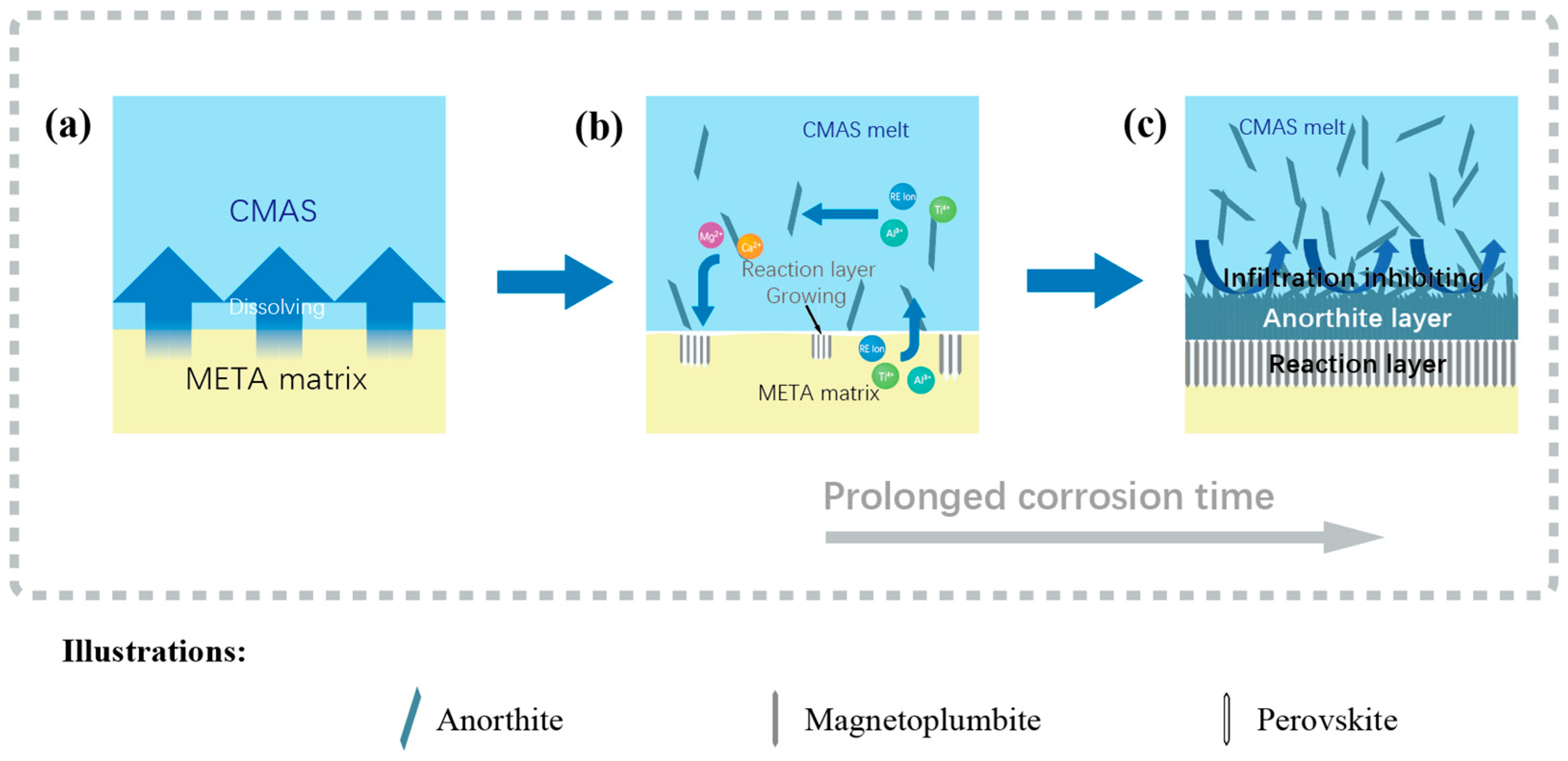
3.6. CMAS Infiltration Inhibiting Mechanism

4. Conclusions
- (1)
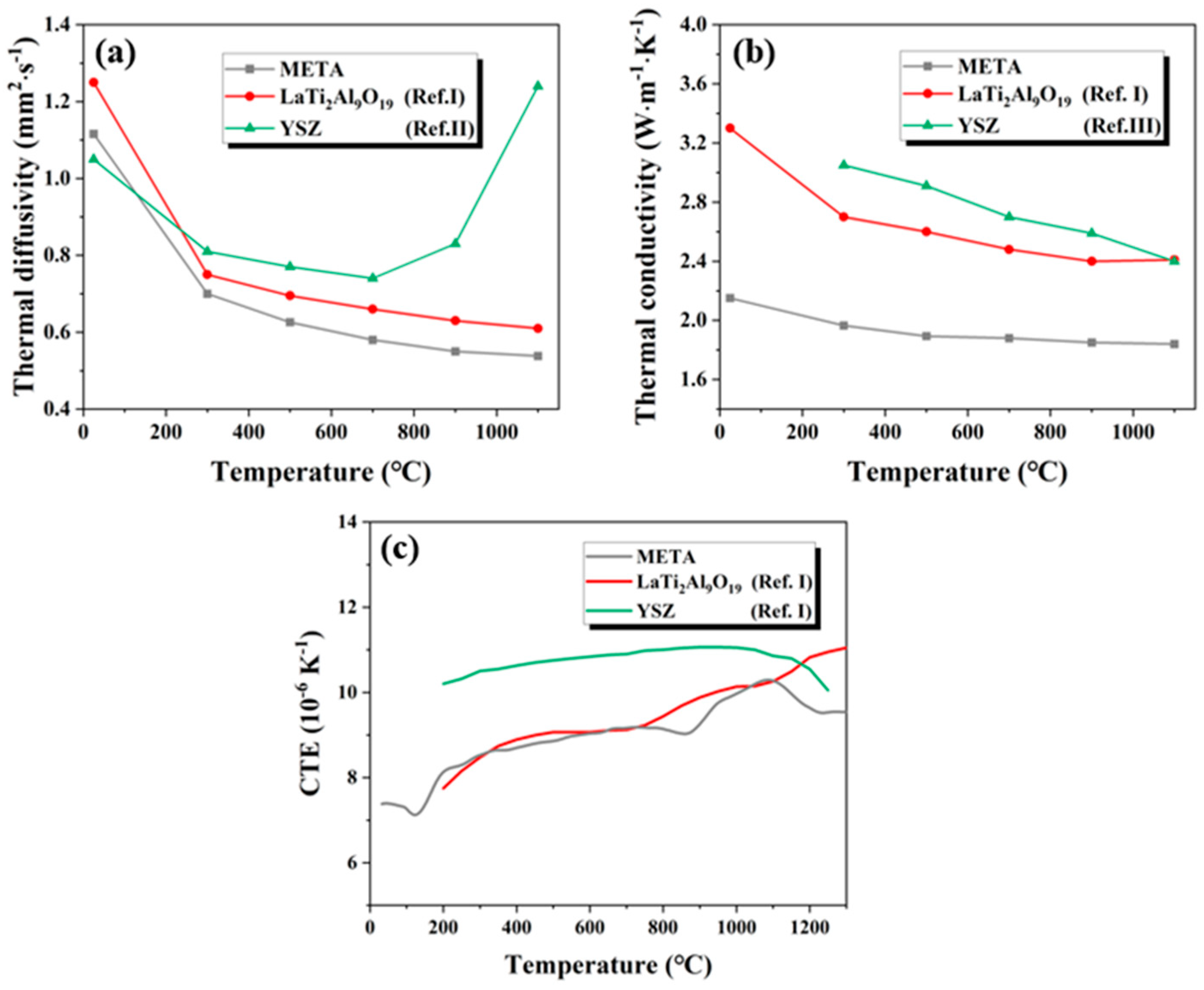
- META exhibits exceptional thermophysical and mechanical properties. The incorporation of atoms with different radii results in low thermal conductivity (1.84–2.15 W·(m·K)−1). The experimental results demonstrated that the CTE of META exhibits fluctuations with temperature, which has an impact on its thermal cycling performance. However, in general, the CTE of META is comparable to that of YSZ, which significantly mitigates the detrimental effects of thermal mismatch on its thermal shielding performance.
- (2)
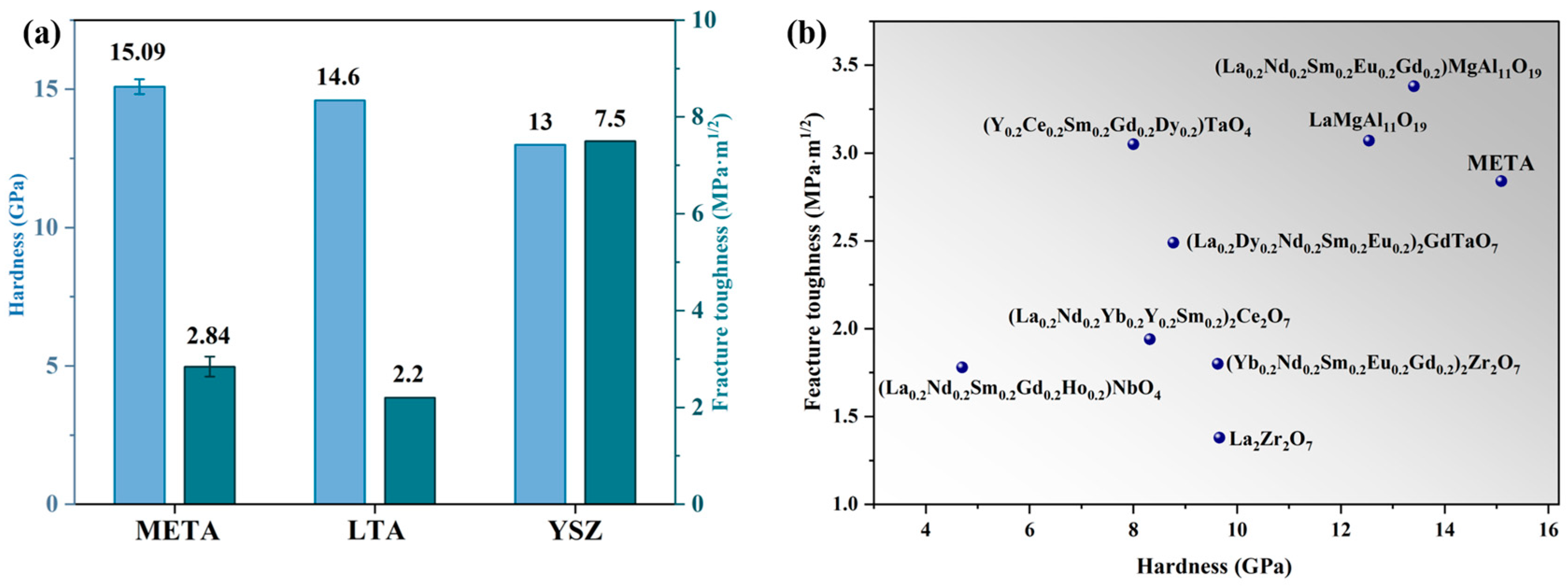
- META has a high hardness (15.10 GPa), good fracture toughness (2.20 MPa·m1/2), and high infrared emissivity in the range of 2.5 to 10 μm, with an average value of 0.86. The mechanical properties of META can assist in the prolongation of the operational lifespan of TBCs. Consequently, at elevated temperatures META becomes infrared opaque, reducing the photon mean free path and minimizing the contribution of radiative heat transfer to thermal conductivity. This ultimately reduces the thermal conductivity at high temperatures.
- (3)
- META has been demonstrated to be an effective inhibitor of corrosion in CMAS. The combined effects of delayed diffusion, increased viscosity of molten CMAS, the barrier effect of the self-crystallized product layer, and improved high-temperature stability of the reaction layer serve to enhance the ability of META to resist the penetration and corrosion of molten CMAS.
Author Contributions
Funding
Institutional Review Board Statement
Informed Consent Statement
Data Availability Statement
Conflicts of Interest
References
- Padture, N.P. Advanced structural ceramics in aerospace propulsion. Nat. Mater. 2016, 15, 804–809. [Google Scholar]
- Wei, Z.Y.; Dong, X.X.; Cai, H.N.; Li, G.R.; Zhao, S.D. Vertical crack distribution effect on the TBC delamination induced by crack growth from the ceramic surface and near the interface. Ceram. Int. 2022, 48, 33028–33040. [Google Scholar] [CrossRef]
- Godiganur, V.S.; Nayaka, S.; Kumar, G.N. Thermal barrier coating for diesel engine application—A review. Mater. Today-Proc. 2021, 45, 133–137. [Google Scholar] [CrossRef]
- Kumar, V.; Kandasubramanian, B. Processing and design methodologies for advanced and novel thermal barrier coatings for engineering applications. Particuology 2016, 27, 1–28. [Google Scholar] [CrossRef]
- Cheng, Z.; Zahiri, B.; Ji, X.Y.; Chen, C.; Chalise, D.; Braun, P.V.; Cahill, D.G. Good Solid-State Electrolytes Have Low, Glass-Like Thermal Conductivity. Small 2021, 17, 2101693. [Google Scholar] [CrossRef] [PubMed]
- Cao, X.Q.; Vassen, R.; Stoever, D. Ceramic materials for thermal barrier coatings. J. Eur. Ceram. Soc. 2004, 24, 1–10. [Google Scholar]
- Poerschke, D.L.; Jackson, R.W.; Levi, C.G. Silicate Deposit Degradation of Engineered Coatings in Gas Turbines: Progress Toward Models and Materials Solutions. Annu. Rev. Mater. Res. 2017, 47, 297–330. [Google Scholar] [CrossRef]
- Zhu, H.L.; Liu, L.; Xiang, H.M.; Dai, F.Z.; Wang, X.H.; Ma, Z.; Liu, Y.B.; Zhou, Y.C. Improved thermal stability and infrared emissivity of high-entropy REMgAl11O19 and LaMAl11O19 (RE = La, Nd, Gd, Sm, Pr, Dy; M = Mg, Fe, Co, Ni, Zn). J. Mater. Sci. Technol. 2022, 104, 131–144. [Google Scholar] [CrossRef]
- Liu, H.Z.; Ouyang, J.H.; Liu, Z.G.; Wang, Y.M. Microstructure, thermal shock resistance and thermal emissivity of plasma sprayed LaMAl11O19 (M = Mg, Fe) coatings for metallic thermal protection systems. Appl. Surf. Sci. 2013, 271, 52–59. [Google Scholar] [CrossRef]
- Yin, J.H.; Zhang, M.; Zhou, T.; Xiang, Y.; Ma, W.Z.; Zhong, M.; Zhang, H.Z.; Zhou, C.; Han, M.; Tu, X.G.; et al. Investigating the mechanism of infrared emissivity control in MgO doped YSZ based ceramics. Infrared Phys. Technol. 2024, 138, 105235. [Google Scholar] [CrossRef]
- Tu, T.Z.; Liu, J.X.; Zhou, L.; Liang, Y.C.; Zhang, G.J. Graceful behavior during CMAS corrosion of a high-entropy rare-earth zirconate for thermal barrier coating material. J. Eur. Ceram. Soc. 2022, 42, 649–657. [Google Scholar]
- Meng, F.W.; Ye, F.X.; Luo, T.Y. The high-temperature CMAS corrosion behavior of high-entropy (La0.2Nd0.2Sm0.2Eu0.2Gd0.2)2Hf2O7 hafnate thermal barrier coating material with fluorite structure. J. Eur. Ceram. Soc. 2024, 44, 2460–2470. [Google Scholar]
- Wang, Y.H.; Liu, Z.G.; Ouyang, J.H.; Wang, Y.M.; Wang, Y.J. Dependence of the infrared emissivity on SiC content and microstructure of microarc oxidation ceramic coatings formed in Na2SiO3 electrolyte. Appl. Surf. Sci. 2018, 431, 17–23. [Google Scholar] [CrossRef]
- Gan, M.D.; Chong, X.Y.; Yu, W.; Xiao, B.; Feng, J. Understanding the ultralow lattice thermal conductivity of monoclinic RETaO4 from acoustic-optical phonon anti-crossing property and a comparison with ZrO2. J. Am. Ceram. Soc. 2023, 106, 3103–3115. [Google Scholar]
- Yan, R.X.; Liang, W.P.; Miao, Q.; Zhao, H.; Liu, R.X.; Li, J.L.; Zang, K.; Dong, M.J.; He, X.P.; Gao, X.G.; et al. Mechanical, thermal and CMAS resistance properties of high-entropy (Gd0.2Y0.2Er0.2Tm0.2Yb0.2)2Zr2O7 ceramics. Ceram. Int. 2023, 49, 20729–20741. [Google Scholar] [CrossRef]
- Vassen, R.; Cao, X.Q.; Tietz, F.; Basu, D.; Stöver, D. Zirconates as new materials for thermal barrier coatings. J. Am. Ceram. Soc. 2000, 83, 2023–2028. [Google Scholar]
- Xie, X.Y.; Guo, H.B.; Gong, S.K.; Xu, H.B. Lanthanum-titanium-aluminum oxide: A novel thermal barrier coating material for applications at 1300 °C. J. Eur. Ceram. Soc. 2011, 31, 1677–1683. [Google Scholar]
- Dhineshkumar, S.R.; Duraiselvam, M.; Natarajan, S.; Panwar, S.S.; Jana, T.; Khan, M.A. Effect of laser glazing on the thermo-mechanical properties of plasma-sprayed LaTi2Al9O19 thermal barrier coatings. Mater. Manuf. Process 2017, 32, 1573–1580. [Google Scholar]
- Yang, Z.S.; Zong, P.A.; Huang, M.Z.; Han, Y.; Zhou, H.J.; Feng, Y.J.; Zhang, P.; Wan, C.L. Effect of Heat Treatment on LaTi2Al9O19-Zr0.92Y0.08O1.96 Composite Coating Powders by Air Plasma Spraying. Rare Met. Mater. Eng. 2022, 51, 1601–1605. [Google Scholar]
- Dhineshkumar, S.R.; Duraiselvam, M.; Natarajan, S.; Panwar, S.S.; Jena, T.; Khan, M.A. Enhancement of strain tolerance of functionally graded LaTi2Al9O19 thermal barrier coating through ultra-short pulse-based laser texturing. Surf. Coat. Technol. 2016, 304, 263–271. [Google Scholar]
- Zhou, X.; Xu, Z.H.; He, L.M.; Xu, J.Y.; Zou, B.L.; Cao, X.Q. Hot corrosion behavior of LaTi2Al9O19 ceramic exposed to vanadium oxide at temperatures of 700–950 °C in air. Corros. Sci. 2016, 104, 310–318. [Google Scholar]
- Oses, C.; Toher, C.; Curtarolo, S. High-entropy ceramics. Nat. Rev. Mater. 2020, 5, 295–309. [Google Scholar]
- Zhang, R.Z.; Reece, M.J. Review of high entropy ceramics: Design, synthesis, structure and properties. J. Mater. Chem. A 2019, 7, 22148–22162. [Google Scholar]
- Ye, F.X.; Meng, F.W.; Luo, T.Y.; Qi, H. Ultrafast high-temperature sintering of high-entropy (La0.2Nd0.2Sm0.2Eu0.2Gd0.2)2Hf2O7 ceramics with fluorite structure. Ceram. Int. 2022, 48, 35649–35654. [Google Scholar]
- Luo, X.W.; Huang, S.; Xu, C.H.; Hou, S.E.; Jin, H.Y. Rare-earth high-entropy aluminate-toughened-zirconate dual-phase composite ceramics for advanced thermal barrier coatings. Ceram. Int. 2023, 49, 766–772. [Google Scholar]
- Gild, J.; Samiee, M.; Braun, J.L.; Harrington, T.; Vega, H.; Hopkins, P.E.; Vecchio, K.; Luo, J. High-entropy fluorite oxides. J. Eur. Ceram. Soc. 2018, 38, 3578–3584. [Google Scholar]
- Zhang, P.; Gong, L.Y.; Lou, Z.H.; Xu, J.; Cao, S.Y.; Zhu, J.T.; Yan, H.X.; Gao, F. Reduced lattice thermal conductivity of perovskite-type high-entropy (Ca0.25Sr0.25Ba0.25RE0.25)TiO3 ceramics by phonon engineering for thermoelectric applications. J. Alloys Compd. 2022, 898, 162858. [Google Scholar]
- Luo, X.W.; Huang, S.; Huang, R.Q.; Hong, J.H.; Yuan, S.G.; Shu, Z.; Zhao, L.; Lu, C.; Jin, H.Y. Rare-earth high-entropy magnetoplumbite structure hexaluminates (La0.2Nd0.2Sm0.2Eu0.2Gd0.2)MAl11O19 (M = Mg, Zn) for thermal barrier coating applications with enhanced mechanical and thermal properties. Ceram. Int. 2024, 50, 21281–21288. [Google Scholar]
- Luo, X.W.; Huang, R.Q.; Xu, C.H.; Huang, S.; Hou, S.; Jin, H.Y. Designing high-entropy rare-earth zirconates with tunable thermophysical properties for thermal barrier coatings. J. Alloys Compd. 2022, 926, 166714. [Google Scholar]
- Yang, Q.; Zhao, L.R. Characterization of nano-layered multilayer coatings using modified Bragg law. Mater. Charact. 2008, 59, 1285–1291. [Google Scholar]
- Huang, L.L.; Meng, H.M.; Tang, J. Crystallization behavior of plasma-sprayed lanthanide magnesium hexaaluminate coatings. Int. J. Min. Met. Mater. 2014, 21, 1247–1253. [Google Scholar]
- Mikuskiewicz, M.; Migas, D.; Moskal, G. Synthesis and thermal properties of zirconate, hafnate and cerate of samarium. Surf. Coat. Technol. 2018, 354, 66–75. [Google Scholar]
- Ren, K.; Wang, Q.K.; Shao, G.; Zhao, X.F.; Wang, Y.G. Multicomponent high-entropy zirconates with comprehensive properties for advanced thermal barrier coating. Scripta Mater. 2020, 178, 382–386. [Google Scholar]
- Klemens, P.G. Phonon scattering by oxygen vacancies in ceramics. Physics B 1999, 263, 102–104. [Google Scholar]
- Nettleton, R.E. Foundations of the Callaway theory of thermal conductivity. Phys. Rev. Lett. 1963, 132, 2032–2038. [Google Scholar]
- Heine, V.; Welche, P.R.; Dove, M.T. Geometrical origin and theory of negative thermal expansion in framework structures. J. Am. Ceram. Soc. 1999, 82, 1793–1802. [Google Scholar]
- Liu, H.W.; Liu, L.; Xiang, H.M.; Dai, F.Z.; Wang, X.H.; Huang, M.Z.; Wan, C.L.; Ma, Z.; Liu, Y.B.; Li, H.Z.; et al. Orthorhombic to tetragonal polymorphic transformation of YTa3O9 and its inhibition through the design of high-entropy (Y0.2La0.2Ce0.2Nd0.2Gd0.2)Ta3O9. J. Eur. Ceram. Soc. 2022, 42, 3559–3569. [Google Scholar]
- Zhang, Y.L.; Guo, L.; Yang, Y.P.; Guo, H.B.; Zhang, H.J.; Gong, S.K. Influence of Gd2O3 and Yb2O3 Co-doping on Phase Stability, Thermo-physical Properties and Sintering of 8YSZ. Chin. J. Aeronaut. 2012, 25, 948–953. [Google Scholar]
- Lu, X.R.; Yuan, J.Y.; Li, G.; Xu, M.Y.; Lu, G.Q.; Zhang, Y.X.; Yuan, F.H.; Huang, J.Q.; Deng, L.H.; Jiang, J.N.; et al. Preparation and properties evaluation of high-entropy (La0.2Nd0.2Sm0.2Eu0.2Gd0.2)MgAl11O19 for advanced thermal barrier coating. J. Eur. Ceram. Soc. 2024, 44, 6641–6650. [Google Scholar]
- Zhu, J.T.; Meng, X.Y.; Zhang, P.; Li, Z.L.; Xu, J.; Reece, M.J.; Gao, F. Dual-phase rare-earth-zirconate high-entropy ceramics with glass-like thermal conductivity. J. Eur. Ceram. Soc. 2021, 41, 2861–2869. [Google Scholar]
- Chen, L.; Hu, M.Y.; Wu, P.; Feng, J. Thermal expansion performance and intrinsic lattice thermal conductivity of ferroelastic RETaO4 ceramics. J. Am. Ceram. Soc. 2019, 102, 4809–4821. [Google Scholar] [CrossRef]
- Zhu, J.T.; Lou, Z.H.; Zhang, P.; Zhao, J.; Meng, X.Y.; Xu, J.; Gao, F. Preparation and Thermal Properties of Rare Earth Tantalates (RETaO4) High-Entropy Ceramics. J. Inorg. Mater. 2021, 36, 411–417. [Google Scholar] [CrossRef]
- Gu, S.Y.; Zhang, S.Y.; Xue, B.; Yan, J.K.; Li, W.; Zhang, L.L. Phase variation and thermophysical properties of La2Hf2O7 with alumina addition. J. Eur. Ceram. Soc. 2018, 38, 1938–1945. [Google Scholar] [CrossRef]
- Cong, L.K.; Zhang, S.Y.; Gu, S.Y.; Li, W. Thermophysical properties of a novel high entropy hafnate ceramic. J. Mater. Sci. Technol. 2021, 85, 152–157. [Google Scholar] [CrossRef]
- Zhu, J.T.; Meng, X.Y.; Xu, J.; Zhang, P.; Lou, Z.H.; Reece, M.J.; Gao, F. Ultra-low thermal conductivity and enhanced mechanical properties of high-entropy rare earth niobates (RE3NbO7, RE = Dy, Y, Ho, Er, Yb). J. Eur. Ceram. Soc. 2021, 41, 1052–1057. [Google Scholar] [CrossRef]
- Ren, X.M.; Tian, Z.L.; Zhang, J.; Wang, J.Y. Equiatomic quaternary (Y0.25Ho0.25Er0.25Yb0.25)2SiO5 silicate: A perspective multifunctional thermal and environmental barrier coating material. Scr. Mater. 2019, 168, 47–50. [Google Scholar] [CrossRef]
- Sarker, P.; Harrington, T.; Toher, C.; Oses, C.; Samiee, M.; Maria, J.P.; Brenner, D.W.; Vecchio, K.S.; Curtarolo, S. High-entropy high-hardness metal carbides discovered by entropy descriptors. Nat. Commun. 2018, 9, 4980. [Google Scholar] [CrossRef]
- Zhao, M.; Ren, X.R.; Pan, W. Mechanical and thermal properties of simultaneously substituted pyrochlore compounds (Ca2Nb2O7)x(GdZrO)1−x. J. Eur. Ceram. Soc. 2015, 35, 1055–1061. [Google Scholar] [CrossRef]
- Zhu, J.T.; Xu, J.; Zhang, P.; Meng, X.Y.; Cao, S.Y.; Wu, J.M.; Wei, M.Y.; Shi, Y.S.; Reece, M.J.; Gao, F. Enhanced mechanical and thermal properties of ferroelastic high-entropy rare-earth-niobates. Scr. Mater. 2021, 200, 113912. [Google Scholar] [CrossRef]
- Tang, A.; Li, B.; Sang, W.W.; Hongsong, Z.; Chen, X.G.; Zhang, H.M.; Ren, B. Thermophysical performances of high-entropy (La0.2Nd0.2Yb0.2Y0.2Sm0.2)Ce2O7 and (La0.2Nd0.2Yb0.2Y0.2Lu0.2)Ce2O7 oxides. Ceram. Int. 2022, 48, 5574–5580. [Google Scholar] [CrossRef]
- Zhang, H.M.; Zhang, H.S.; Liu, S.X.; Zhang, X.P.; Chen, X.G.; Wang, H.; Wang, Y.H.; Duan, H.L.; Xue, Y.F. (La0.2Dy0.2Nd0.2Sm0.2Eu0.2)2GdTaO7: A promising candidate oxides for high-temperature coating applications. J. Mater. Res. Technol. 2023, 25, 6511–6523. [Google Scholar] [CrossRef]
- Wang, J.; Wu, F.S.; Zou, R.A.; Wu, Y.S.; Gan, M.D.; Feng, J.; Chong, X.Y. High-entropy ferroelastic rare-earth tantalite ceramic: (Y0.2Ce0.2Sm0.2Gd0.2Dy0.2)TaO4. J. Am. Ceram. Soc. 2021, 104, 5873–5882. [Google Scholar] [CrossRef]
- Zmeskal, D.; Buchnicek, M.; Vala, M. Thermal properties of bodies in fractal and Cantorian physics. Chaos Soliton Fract. 2005, 25, 941–954. [Google Scholar] [CrossRef]
- Liu, L.; Zhang, S.Y.; Ma, Z.; Zhu, S.Z. Effects of Ca2+-Sr2+ doping on the infrared emissivity of LaCrO3. Ceram. Int. 2020, 46, 19738–19742. [Google Scholar] [CrossRef]
- Sarkar, A.; Eggert, B.; Velasco, L.; Mu, X.K.; Lill, J.; Ollefs, K.; Bhattacharya, S.S.; Wende, H.; Kruk, R.; Brand, R.A.; et al. Role of intermediate 4f states in tuning the band structure of high entropy oxides. APL Mater. 2020, 8, 051111. [Google Scholar]
- Sarkar, A.; Loho, C.; Velasco, L.; Thomas, T.; Bhattacharya, S.S.; Hahn, H.; Djenadic, R. Multicomponent equiatomic rare-earth oxides with a narrow band gap and associated praseodymium multivalency. Dalton Trans. 2017, 46, 12167–12176. [Google Scholar]
- Liu, H.Z.; Liu, Z.G.; Ouyang, J.H.; Wang, Y.M. Thermo-optical properties of LaMg1−xNixAl11O19(0 ≤ x ≤ 1) hexaaluminates for metallic thermal protection system. Mater. Lett. 2011, 65, 2614–2617. [Google Scholar]
- Qu, W.W.; Li, S.S.; Chen, Z.H.; Li, C.; Pei, Y.L.; Gong, S.K. Hot corrosion behavior and wettability of calcium-magnesium-alumina-silicate (CMAS) on LaTi2Al9O19 ceramic. Corros. Sci. 2020, 162, 108199. [Google Scholar]
- Guo, L.; Xin, H.; Li, Y.Y.; Yu, Y.; Yan, Z.; Hu, C.W.; Ye, F.X. Self-crystallization characteristics of calcium-magnesium-alumina-silicate (CMAS) glass under simulated conditions for thermal barrier coating applications. J. Eur. Ceram. Soc. 2020, 40, 5683–5691. [Google Scholar]
- Cong, L.K.; Li, W.; Song, Q.; Guo, Y.; Wang, J.C.; Gu, S.Y.; Zhang, S.Y. Hot corrosion of high-entropy hafnate for thermal barrier coating material subjected to molten CMAS. Corros. Sci. 2022, 209, 110714. [Google Scholar]
- Yan, Z.; Guo, L.; Zhang, Z.; Wang, X.H.; Ye, F.X. Versatility of potential protective layer material Ti2AlC on resisting CMAS corrosion to thermal barrier coatings. Corros. Sci. 2020, 167, 108532. [Google Scholar] [CrossRef]
- Webster, R.I.; Opila, E.J. The effect of TiO2 additions on CaO-MgO-Al2O3-SiO2 (CMAS) crystallization behavior from the melt. J. Am. Ceram. Soc. 2019, 102, 3354–3367. [Google Scholar] [CrossRef]
- Zhang, G.H.; Chou, K.C.; Mills, K. Modelling Viscosities of CaO-MgO-Al2O3-SiO2 Molten Slags. ISIJ Int. 2012, 52, 355–362. [Google Scholar] [CrossRef]
- Jing, J.; Li, J.M.; He, Z.; He, J.; Guo, H.B. High-temperature CMAS resistance performance of Ti2AlC oxide scales. Corros. Sci. 2020, 174, 108832. [Google Scholar] [CrossRef]
- Zhen, Y.L.; Zhang, G.H.; Chou, K.C. Influence of Al2O3/TiO2 Ratio on Viscosities and Structure of CaO-MgO-Al2O3-SiO2-TiO2 Melts. ISIJ Int. 2014, 54, 985–989. [Google Scholar] [CrossRef]
- Zhou, X.; Wang, J.S.; Yuan, J.Y.; Sun, J.B.; Dong, S.J.; He, L.M.; Cao, X.G. Calcium-magnesium-aluminon-silicate induced degradation and failure of La2(Zr0.3Ce0.7)2O7/YSZ double-ceramic-layer thermal barrier coatings prepared by electron beam-physical vapor deposition. J. Eur. Ceram. Soc. 2018, 38, 1897–1907. [Google Scholar] [CrossRef]
- Lv, C.; Lin, C.; Zhao, X.S. Enhancing low-temperature electrochemical kinetics and high-temperature cycling stability by decreasing ionic packing factor. eScience 2023, 3, 100179. [Google Scholar] [CrossRef]
- Aygun, A.; Vasiliev, A.L.; Padture, N.P.; Ma, X.Q. Novel thermal barrier coatings that are resistant to high-temperature attack by glassy deposits. Acta Mater. 2007, 55, 6734–6745. [Google Scholar] [CrossRef]
- Ou, J.N.; Bin, X.; Liu, Z.H.; Sun, J.B.; Lu, W.H. CMAS corrosion behavior of LaMgAl11O19/CeO2 ceramic materials. J. Eur. Ceram. Soc. 2024, 44, 3747–3759. [Google Scholar] [CrossRef]


| Compounds | Thermal Conductivity (W·(m·K)−1) | CTE (10−6 K−1) |
|---|---|---|
| META (This work) | 1.84–2.15, 300–1100 °C | 8.13–10.50, 200–1300 °C |
| YSZ [38] | 2.40–3.04, 100–900 °C | 11, 1200 °C |
| LaMgAl11O19 [39] | 2.62, 1000 °C | 8.53, 1300 °C |
| (La0.2Nd0.2Sm0.2Eu0.2Gd0.2)MgAl11O19 [39] | 2.19–3.27, 25–1000 °C | 9.22, 1300 °C |
| La2Zr2O7 [40] | 2.3, 1000 °C | 9.1, 1200 °C |
| (Dy0.2Y0.2Ho0.2Er0.2Yb0.2)2Zr2O7 [40] | 2.18, 1000 °C | 10.08, 1200 °C |
| YTaO4 [41] | 1.57–2.88, 100–800 °C | 9.6, 1200 °C |
| GdTaO4 [41] | 1.83–3.61, 100–800 °C | 8.8, 1200 °C |
| (Nd0.25Sm0.25Eu0.25Gd0.25)TaO4 [42] | 2.1–2.97, 100–1000 °C | 8.8, 1200 °C |
| (Nd0.2Sm0.2Eu0.2Gd0.2Dy0.2)TaO4 [42] | 1.94–3.13, 100–1000 °C | 9, 1200 °C |
| La2Hf2O7 [43] | 1.44, 1200 °C | 9.2, 1300 °C |
| (La0.2Ce0.2Pr0.2Sm0.2Eu0.2)2Hf2O7 [44] | 1.00, 800 °C | 12.7, 1200 °C |
| (Dy0.25Er0.25Y0.25Yb0.25)3NbO7 [45] | 0.9, 25 °C | 9.8, 1200 °C |
| (Y0.25Ho0.25Er0.25Yb0.25)2SiO5 [46] | 1.0–1.47, 200–800 °C | 6.6, 1460 °C |
| Corrosion Condition | Position/at% | Ca | Si | Mg | La | Ce | Nd | Sm | RE Total | Ti | Al | O |
|---|---|---|---|---|---|---|---|---|---|---|---|---|
| 1250 °C/3 h | A1 | 7.2 | - | 1.5 | 0.9 | 1.1 | 0.9 | 1.1 | 4.0 | 9.2 | 23.7 | 54.4 |
| A2 | 4.4 | - | 2.3 | 0.7 | 0.7 | 0.6 | 0.6 | 2.6 | 4.3 | 35.6 | 50.9 | |
| A3 | 12.9 | 27.5 | - | - | - | - | - | - | - | 23.4 | 35.8 | |
| A4 | 19.7 | 29.7 | 6.1 | 0.2 | 0.3 | 0.3 | 0.3 | 1.1 | 1.4 | 5.4 | 36.3 | |
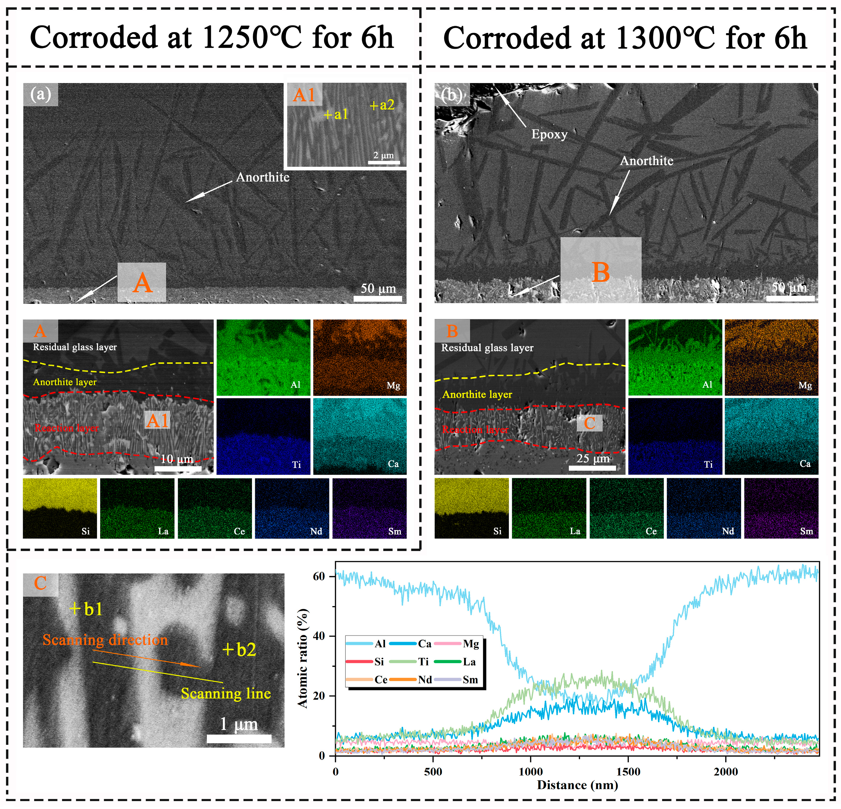
| 1250 °C/6 h | a1 | 9.9 | - | 1.1 | 1.0 | 1.4 | 1.6 | 1.8 | 4.8 | 14.1 | 18.5 | 50.5 |
| a2 | 4.2 | - | 2.2 | 0.8 | 0.8 | 0.6 | 0.6 | 2.8 | 4.2 | 37.3 | 49.4 | |
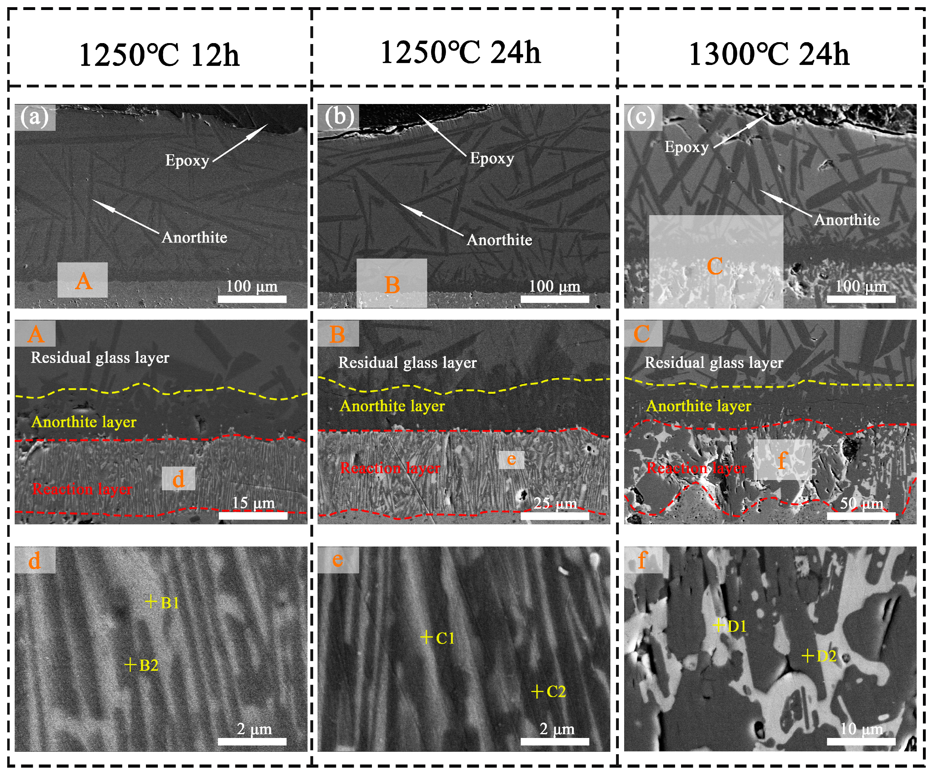
| 1250 °C/12 h | B1 | 12.2 | - | 1.3 | 0.9 | 1.3 | 1.4 | 1.3 | 4.9 | 13.9 | 15.7 | 51.9 |
| B2 | 3.8 | - | 2.3 | 0.8 | 0.7 | 0.7 | 0.6 | 2.8 | 4.1 | 37.9 | 50.4 | |
| 1250 °C/24 h | C1 | 12.1 | - | 1.4 | 0.9 | 1.2 | 1.2 | 1.5 | 4.8 | 14.5 | 14.8 | 51.3 |
| C2 | 3.6 | - | 2.2 | 0.8 | 0.8 | 0.5 | 0.6 | 2.7 | 3.4 | 39.9 | 50.7 | |
| 1300 °C/6 h | b1 | 10.9 | - | - | 1.3 | 2.1 | 2.5 | 3.4 | 9.3 | 19.7 | 9.5 | 50.2 |
| b2 | 2.5 | - | 2.7 | 0.8 | 0.6 | 0.5 | 0.4 | 2.3 | 1.6 | 41.5 | 48.0 | |
| 1300 °C/24 h | D1 | 12.6 | - | - | 1.2 | 1.7 | 2.7 | 3.4 | 9.0 | 21.9 | 3.5 | 52.7 |
| D2 | 2.0 | - | 2.6 | 0.6 | 0.6 | 0.4 | 0.4 | 2.0 | 1.2 | 42.86 | 49.6 |
| Chemical Formula | Crystalline Structure | Abbreviation | Marked Points | Description |
|---|---|---|---|---|
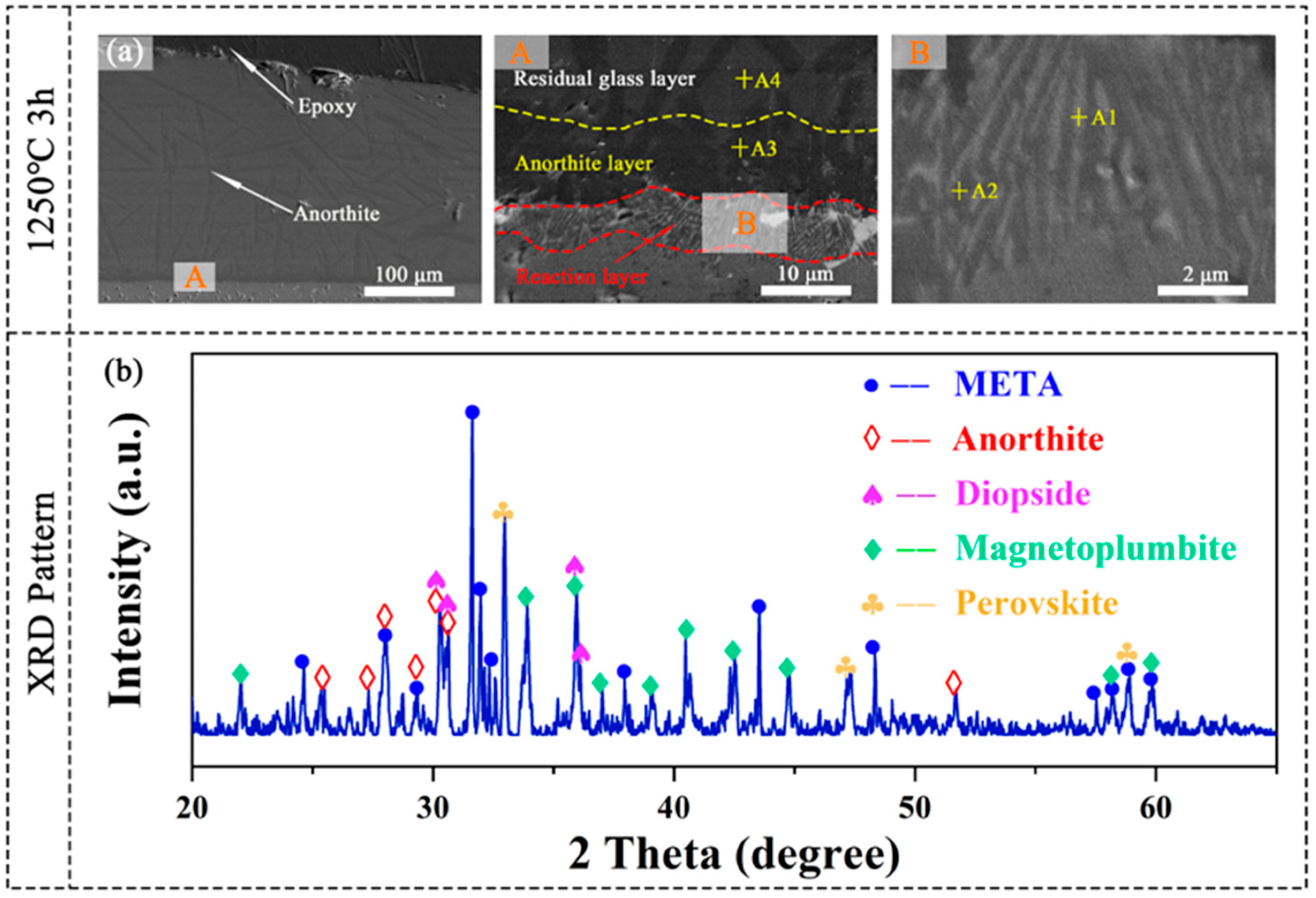
| CaAl2Si2O8 | Anorthite | An | A3 | Calcium aluminosilicate |
| RE(Ca, Mg)Al11O19 | Magnetoplumbite | Mag | a2, b2, A2, B2, C2, D2 | Magnetoplumbite-type rare-earth hexaaluminate |
| (Ca, RE)(Ti, Al)O3 | Perovskite | Prv | a1, b1, A1, B1, C1, D1 | Multicomponent perovskite solid solution |
| Ca33Mg9Al13Si45 | - | CMAS | A4 | Molten salts |
Disclaimer/Publisher’s Note: The statements, opinions and data contained in all publications are solely those of the individual author(s) and contributor(s) and not of MDPI and/or the editor(s). MDPI and/or the editor(s) disclaim responsibility for any injury to people or property resulting from any ideas, methods, instructions or products referred to in the content. |
© 2025 by the authors. Licensee MDPI, Basel, Switzerland. This article is an open access article distributed under the terms and conditions of the Creative Commons Attribution (CC BY) license (https://creativecommons.org/licenses/by/4.0/).
Share and Cite
Ye, F.; Song, Z.; Meng, F.; Ali, S. Properties Evaluation of a Novel Entropy-Stabilized Ceramic (La0.25Ce0.25Nd0.25Sm0.25)Ti2Al9O19 with Enhanced CMAS Corrosion Resistance for Thermal Barrier Coating Applications. Materials 2025, 18, 1778. https://doi.org/10.3390/ma18081778
Ye F, Song Z, Meng F, Ali S. Properties Evaluation of a Novel Entropy-Stabilized Ceramic (La0.25Ce0.25Nd0.25Sm0.25)Ti2Al9O19 with Enhanced CMAS Corrosion Resistance for Thermal Barrier Coating Applications. Materials. 2025; 18(8):1778. https://doi.org/10.3390/ma18081778
Chicago/Turabian StyleYe, Fuxing, Ziqi Song, Fanwei Meng, and Sajid Ali. 2025. "Properties Evaluation of a Novel Entropy-Stabilized Ceramic (La0.25Ce0.25Nd0.25Sm0.25)Ti2Al9O19 with Enhanced CMAS Corrosion Resistance for Thermal Barrier Coating Applications" Materials 18, no. 8: 1778. https://doi.org/10.3390/ma18081778
APA StyleYe, F., Song, Z., Meng, F., & Ali, S. (2025). Properties Evaluation of a Novel Entropy-Stabilized Ceramic (La0.25Ce0.25Nd0.25Sm0.25)Ti2Al9O19 with Enhanced CMAS Corrosion Resistance for Thermal Barrier Coating Applications. Materials, 18(8), 1778. https://doi.org/10.3390/ma18081778