Abstract
The development of low-carbon fuels from renewable resources is a key measure to reduce carbon dioxide emissions and mitigate climate change. Biomass gasification with subsequent gas processing and purification is a promising route to produce low-carbon hydrogen. In the past decade, simulation-based modelling using Aspen Plus software has supported the investigation of future potential industrial applications of this pathway. This article aims to provide a review of the modelling and economic assessment of woody biomass gasification-based hydrogen production, with focus on the evaluation of the model accuracy in predicting producer gas composition in comparison with experimental data depending on the approach implemented. The assessment of comprehensive models, which integrate biomass gasification with gas processing and purification, highlights how downstream gas processing could improve the quality of the syngas and, thus, the hydrogen yield. The information in this article provides an overview of the current practices, challenges, and opportunities for future research, particularly for the development of a comprehensive pathway for hydrogen production based on biomass gasification. Moreover, this review includes a techno-economic assessment of biomass to hydrogen processes, which will be useful for implementation at industrial-scale.
1. Introduction
The continued growth of the human population and industrialisation demands caused a persistent increase in global energy consumption, leading to a steady rise in CO2 emissions. In 2020, the energy-related emissions worldwide were at 31.5 Gt despite the 5.8% decline in global CO2 emissions due to the hit of the pandemic in energy demand. Given this current trend, measures have been proposed to reduce CO2 emissions, which cover clean energy development and implementation, including green hydrogen, synthetic natural gas and liquid fuels along with carbon capture and storage (CCS) [1].
Presently, hydrogen is largely used in oil refineries as a processing agent and in chemical production processes [2]. However, with the global effort to reduce CO2 emissions, hydrogen as a clean energy carrier has recently been used in the energy and transportation sectors to substitute conventional gaseous and liquid fuels. Thus, green hydrogen from renewable resources has been regarded as an environmentally friendly, efficient, inexhaustible, and cost-attractive energy carrier in the future [3].
Green hydrogen currently contributes less than 5% toward the world’s hydrogen demand and is mainly produced from water electrolysis [2]. The dramatic increase in hydrogen production from this pathway requires a huge supply of renewable electricity. Green hydrogen can also be produced from biomass resources through various conversion technologies. Biomass gasification is one of the most well-known thermal processes in converting carbonaceous materials such as woody biomass to hydrogen-rich synthetic gas, which can then be processed for pure hydrogen production. It could produce energy from biomass at a lower cost than conventional technologies because of its superior energy conversion efficiency [4].
The overall performance of hydrogen production from biomass is assessed on conversion and energy efficiencies, hydrogen purity, and economic returns. For the biomass gasification-based processes, these parameters are affected by biomass feedstock type, key processing technologies employed, process integration, and operating conditions. Experimental data generation and mathematical modelling for the process simulation are essential tools to evaluate the influence of these parameters on the design and operation of the gasification and subsequent gas processing units on the overall process performance. Although the experimental data generation route remains the most reliable, modelling could serve as a low-cost and effective option for identifying operational limits and for optimising operation parameters [4,5].
In recent years, simulation software such as Aspen Plus has been used to develop either thermodynamic equilibrium [6,7,8,9,10,11,12,13,14] or kinetic-based [15,16,17,18,19,20,21,22,23,24] process models for biomass gasification. These modelling studies provide insights into the operation and understanding of the performance of biomass gasification. The process models can also be used to predict the impacts of the biomass feedstock, gasifier type, gasification agent, and operating conditions. However, biomass gasification models alone are not sufficient to fully evaluate the technical and economic potential of the process to produce high-purity hydrogen from biomass. It is well known that the producer gas from biomass gasification consists of H2, CO, CO2 and CH4, as well as other gaseous species depending on the gasification agent applied. Hence, subsequent gas cleaning and processing are necessary. Recent studies on process modelling have also included downstream gas cleaning and gas processing following the biomass gasification process to evaluate the overall performance of the process for hydrogen production [25,26,27]. These models are useful in economic and environmental assessment and in evaluating the potential for large-scale applications of biomass gasification-based hydrogen production technologies.
The commercial implementation of biomass-sourced energy technologies is dependent on cost-competitiveness compared to conventional fossil fuel-sourced technologies and the green hydrogen from water electrolysis [28,29,30]. The overall technical performance of hydrogen production from biomass gasification-based processes has been evaluated in terms of carbon conversion efficiency and gas quality including its composition, heating value, and cold gas efficiency [31,32,33,34]. Meanwhile, the economics of the process has been assessed in the reported studies using metrics such as total capital investment, production cost, levelised cost of hydrogen, net present value, and selling price [35,36,37,38].
The primary objective of this article is to provide an assessment of the process simulation-based approach for green hydrogen production from woody biomass based on advanced gasification and subsequent gas processing. The review of biomass gasification models focuses on the evaluation of the model accuracy in predicting producer gas composition. The presented comprehensive models, which integrate biomass gasification with gas processing, highlight how downstream gas cleaning, gas processing and purification could affect the yield and quality of the hydrogen produced. In summary, this article provides information on the current practices, challenges, and opportunities for future research, particularly for the development of a comprehensive pathway for hydrogen production from biomass gasification-based processes. Moreover, this article presents an overview of the techno-economic assessment of biomass gasification-based technologies to support the evaluation of the technology’s potential for industrial-scale applications.
2. Woody Biomass
Biomass is an organic matter originating from living plants and animals which includes wood, forest-derived and agriculture-derived wastes, animal waste, municipal solid waste, food processing waste, and aquatic plants although in most cases the biomass covers the solid matter from trees and crops [39]. The biomass can be processed to produce liquid fuel, gaseous fuel, solid fuel, and chemicals through appropriate pathways [40]. However, the production of liquid and gaseous fuels from biomass requires large-scale implementation to make the process efficient and economically viable [4]. Therefore, efforts to develop new processes and to improve the current energy production pathways from biomass continue to grow, particularly for hydrogen production from biomass sources.
Woody biomass, which originated from trees, can include tree stems (wood), residues from log harvesting in the forests (forest residues), residues from wood processing, and demolition wood. It is the oldest form of energy used by humans and has traditionally been used for heat and power. Moreover, the woody biomass could be used as the feedstock in biorefinery processes [41].
2.1. Woody Biomass Chemical Composition
Woody biomass is predominantly composed of cellulose, hemicellulose, and lignin. The fraction of these components varies with the wood species, and the detailed composition data are given in Table 1. In addition, woody biomass also contains 0.2 to 2.5 wt.% inorganic constituents, collectively known as ash, including potassium, calcium, sodium, silicon, phosphorous, and magnesium [39]. Since the chemical composition of the biomass plays the key role in the decomposition of woody biomass, the intrinsic nature and elemental composition of the biomass significantly affect the performance of the processing units and the product quality of the hydrogen. During biomass devolatilisation, which is the initial stage of biomass gasification, the components of cellulose, hemicellulose and lignin decompose to volatile gases, organic vapours, tars, and char [42].

Table 1.
Composition of woody biomass in comparison with straws (wt% dry basis) [42].
The elemental composition of the woody biomass determines the product composition of each processing unit for energy and fuels [43]. The results from the ultimate analysis, proximate analysis, and heating value evaluation guide the exploration of biomass’s thermochemical conversion options. The selected results of the chemical composition of woody biomass from the ultimate and the proximate analyses are presented in Table 2. Steam gasification of woody biomass could yield producer gas with 30–50 vol.% hydrogen depending on the gasifier type, gasification temperature and steam-to-biomass ratio [9,31,33].
Table 2.
Chemical composition of some woody biomass.
2.2. Pre-Treatment and Handling
Pre-treatment of woody biomass, which includes biomass sizing and drying, is a necessary step before the gasification process. These pre-treatments ensure the consistency of the feedstock material and improve the gasification performance and the quality of the syngas [39].
2.2.1. Biomass Size Reduction
Size reduction is normally the first step of biomass pre-treatment step for ensuring consistent biomass sizes for the gasification process. In addition, the drying of smaller and uniformly sized particles is more effective and efficient than the drying of large particles. Depending on the biomass sources, various sizing technologies can be used. When low-quality logs, branches, and damaged logs from log harvesting, and large-sized cut-offs from the wood processing mills, are used as the feedstock, chipping of the biomass is a common practice [39]. In fluidised-bed gasification technologies, particle size is an important parameter for biomass conversion efficiency and syngas quality [45]. Hence, it has been of interest to researchers to evaluate the effect of biomass size on the producer gas composition.
In the study of Huang and Jin [13], the effect of biomass feed particle size was investigated from 0.15 mm to 0.25 mm in the downdraft steam gasification of pinewood, and it was found that the H2/CO ratio was increased by 11.41% with the particle size reducing from 0.25 mm to 0.177 mm, while further reduction from 0.177 mm to 0.15 mm yielded only a 3.75% increase in the H2/CO ratio. Therefore, the particle size of 0.177 mm was considered the optimal particle size in the study considering the cost of broken pine woodchips.
In another study, by Beshenti et al. [20], the effect of particle size on the producer gas composition was studied for wood gasification in a bubbling fluidized bed using air and steam as the gasification agent. The results of the study showed that with particle size reduction from 10 to 7 mm, the contents of H2, CO and CH4 in the producer gas was increased slightly, respectively, from 32.92 to 33.63 vol.%, from 41.23 to 41.72 vol.%, and from 3.8 to 3.9 vol.%, while the CO2 content decreased from 22.02 to 20.68 vol.%. However, the hydrogen yield increased significantly from 42.95 to 51.07% with the biomass particle size decrease, which was attributed to the reduction in diffusion limitations with smaller particles.
The results from previous studies [46,47,48] have shown that larger particles exhibited greater heat transfer resistance during the initial decomposition stage (pyrolysis) in the gasifier, resulting in higher residual char yield. Generally, reducing the particle size improves the carbon conversion and syngas yield, increases hydrogen production, and decreases tar formation. However, too small particles may have an adverse effect due to the high fly-ash entrainment in the gas product, and thus, more effort is needed for the gas cleaning. In addition, the chipping process consumes electricity, and thus, reducing the particle size more than needed is not necessary [20].
2.2.2. Biomass Drying
A high moisture content of biomass feedstock used in gasification is known to extensively increase the heat requirement of the gasifier to vaporize the water [39]. The removal of 1 kg of moisture in the biomass feed requires heat of at least 2260 kJ from the gasification process [49]. Since woody biomass moisture content in fresh state can range from 50 to 100% (dry-basis), drying prior to the gasification process is necessary to reduce the heat requirement for the drying stage within the gasifier. However, if the biomass is sourced from forest residues and wood processing residues, the moisture content can vary significantly. In this case, the drying can be a process to ensure consistent moisture content of the biomass to feed to the gasifier [50].
The target moisture content of woody biomass for the gasification is dependent on the type of gasifier and the gasification agent to be used. The study of Dang et al. [16] showed that an increase in biomass moisture content from 5% to 30% in the air and steam gasification of wood residue in a bubbling fluidized bed gasifier could increase the H2 and CO2 contents in the producer gas from 30 to 35 vol.% and from 30 to 40 vol.%, respectively, while the CO and CH4 contents decreased from 30 to 20 vol.% and from 10 to 8 vol.%, respectively. In biomass steam gasification, the effect of increasing the steam-to-biomass ratio has a similar trend to that of increasing the biomass moisture content, since the vapour from moisture vaporisation in the biomass can play the same role as the injected steam in the gasification process, which enhances steam reforming and water–gas shift reactions in the gasification. However, it is worth noting that the injected steam does not consume as much energy as the biomass moisture, thus improving the gasification efficiency.
In another study, by Doherty et al. [31], on steam gasification of wood chip with moisture content ranging from 5 to 40% in a dual fluidised-bed gasifier, the results showed only a 3.27% increase in hydrogen content (44.76–48.03 vol.%) in the producer gas. It was found that the moisture content has a more significant effect in the cold gas efficiency (CGE) of the process, which was decreased from 94.28% at 5% moisture content to 53.24% at 40% moisture content. Therefore, the biomass moisture content needs to be optimised to achieve high CGE. For a dual fluidised-bed gasifier with steam as the gasification agent, the biomass moisture content of 15 to 25% is desirable to achieve optimum gasification performance and high efficiency [49].
3. Biomass Gasification
Biomass gasification is a promising conversion technology for the production of producer gas, which can then be used for electricity, synthetic natural gas, hydrogen, and liquid fuel. It is considered more advantageous than the biochemical processing route in terms of flexibility in the type of biomass feedstock that it could process [4].
Biomass gasification involves the partial oxidation of biomass fuel to produce a mixture of H2, CO, CH4, and CO2 gases called producer gas or product gas when steam or oxygen is used as the gasification agent. After the gas cleaning to remove tars and contaminant gaseous species in the producer gas, the clean gas (syngas) can be used for the target purpose. The composition and quality of the producer gas are affected by the biomass type, the gasification type, the gasification agent and the gasification operation conditions [41].
3.1. Steam Gasification
Biomass gasification is commonly performed at operation temperatures ranging from 700 to 1200 °C. The whole gasification process can be divided into three stages including moisture vaporisation, initial devolatilisation or decomposition, which is similar to pyrolysis, and gasification reactions both among gases (homogeneous reactions), and between gases and solid char (heterogeneous reaction) [51]. For the biomass steam gasification, heat is provided either through the oxidation reactions happening in the gasifier, when air or oxygen is used in combination with steam as the gasification agent, or provided by combustion of char, as in the dual fluidised-bed (DFB) steam gasifiers.
3.1.1. Drying
Drying entails the removal of the moisture from the biomass feed by evaporation. In this stage, as the biomass is heated inside the gasifier, the moisture starts to evaporate once the biomass is heated above 100 °C. This stage decreases the moisture content of the biomass to as low as 5%, and the moisture evaporation is completed at 200 °C [6,52]. This stage is considerably shorter than other stages, since the biomass feedstock for gasification is commonly pre-dried to a moisture content of 15–25% [53].
3.1.2. Pyrolysis
During the pyrolysis stage, the biomass is heated to 200–700 °C, and the biomass undergoes devolatilisation. At this stage, the thermal decomposition of larger hydrocarbon molecules is facilitated, releasing volatile matter due to the thermal breakdown. Up to the temperature of 700 °C, 70–90% of the volatile components of biomass vaporise, producing a mixture of H2, CO, CO2, CH4, and heavier hydrocarbon gases (tar gases). The other 10–30% portion of the pyrolysis product is composed of a solid char and liquid tar vapours, which condense at reduced temperatures [42,52]. The different biomass components decompose at varying temperatures. Hemicellulose decomposition starts at 203 °C; cellulose decomposition occurs at higher temperatures of 286–426 °C; and lignin decomposition occurs over a wider range of temperatures from 215 to 585 °C [39,43].
The gases released from the drying and pyrolysis stages undergo further reactions which are discussed in the subsequent section. Meanwhile, the tar vapours produced in the pyrolysis stage are converted to light hydrocarbons, non-condensable gases, or remain as the unconverted tar compounds in the subsequent gasification stage.
3.1.3. Gasification Reactions
The chemical reactions involved in this critical gasification stage as well as in the devolatilisation stage are summarized in Table 3 for biomass steam gasification. As presented in the table, the homogeneous and heterogenous reactions comprise both oxidation and reduction reactions. The oxidation reactions are the reactions of combustible substances with oxygen provided by the biomass feedstock when steam is used as the gasification agent. In the case of steam gasification in a DFB gasifier, the oxidation reaction of solid char happens in a separate column wherein air acts as the fluidising and oxidising agent. These combustion reactions supply heat to the other endothermic reactions in the gasification process such as volatile steam reforming, cracking, and water–gas shift reactions [4,42].
Table 3.
Main chemical reactions during biomass steam gasification [3].
The reduction reactions, which occur at a temperature range of 800–100 °C, include endothermic (R7, R8, R12 and R13) and exothermic (R9 and R14) reactions. However, the critical reactions, such as Boudouard, water–gas and steam reforming, make the reduction reactions generally endothermic. Given the chemical equilibrium nature of R7 to R9 and R12 to R14 reactions, products and reactants can coexist considering several competing reactions. Since the composition of products at equilibrium is a function of temperature, the gasification temperature at the gasification stage significantly affects the final composition of the producer gas and its characteristics [42].
3.2. Dual Fluidised-Bed Gasifiers
Gasifiers are generally categorized depending on fluid dynamics (updraft, downdraft, fluidised-bed, or entrained flow), mode of heat transfer (autothermal, allothermal), gasification agents (air, oxygen, or steam blown), and pressure (atmospheric or pressurized) [54,55]. The dual fluidised-bed gasifier is an allothermal type of gasifier with fluidised-bed configuration.
One type of DFB gasifier comprises an integrated bubbling fluidised bed (BFB) and circulating fluidised bed (CFB), as illustrated in Figure 1. In this type of gasifier system, the gasification occurs in the BFB gasifier at 700–900 °C, while the char combustion occurs in the CFB combustor. It uses steam as the gasification agent and an internally circulating bed material to supply the heat required by the endothermic gasification process. The DFB gasifier produces syngas with little or no nitrogen in the BFB and flue gas in the CFB [51,56].
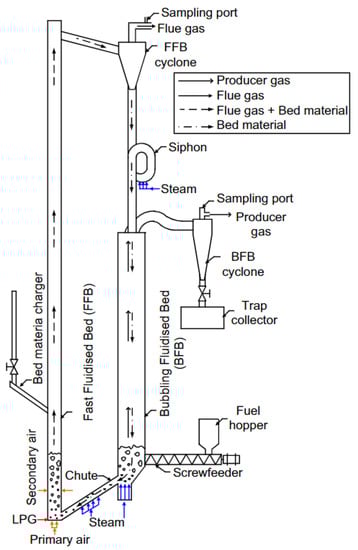
Figure 1.
Schematic diagram of a dual fluidised-bed steam gasifier [57]. (Reprinted from Fuel, Vol. 102, W. Saw and S. Pang. The influence of calcite loading on producer gas composition and tar concentration of radiata pine pellets in a dual fluidised-bed steam gasifier, pp. 445–452, copyright (2012), with permission from Elsevier.)
The DFB steam gasification system is considered a promising technology for the thermochemical conversion of biomass, since it can generate hydrogen-rich producer gas with high heating value and achieve overall high energy efficiency [58]. However, due to the complex equipment configuration compared to other types of gasifiers, careful operation of DFB is required to maintain steady conditions, particularly with the circulating bed material [51]. Nevertheless, it is noteworthy that the DFB gasifier has found application in process intensification such as in the integration of biomass gasification with in situ CO2 adsorption using calcite as catalytic bed materials. Detailed reviews on the available DFB gasification technologies in pilot and demonstration scales and current developments on such technologies are available elsewhere [54,55,56].
The performance indicators in biomass gasification include quality of the syngas in terms of composition and heating values, carbon conversion efficiency, and cold gas efficiency. Among these indicators, syngas composition is one of the most critical measures in evaluating product quality. Various downstream applications of the syngas require different gas compositions. For hydrogen production, the producer gas should have high H2 content and high contents of CO and CH4 which are then converted to H2 and CO2 in the gas processing units following the gasification.
Experimental results from the gasification of woody biomass in pilot scale DFB gasifiers are presented in Figure 2 for the producer gas composition. The operating conditions for these experimental studies are presented in Table 4. It is apparent from these results that DFB steam gasification could generate producer gas with high H2 (30–40 vol.%) and CO (20–35 vol.%) contents. This agrees with the observation of Hanchate that DFB gasifiers can yield producer gas with 30–45 vol.% H2 [56]. It is also notable from these results that the H2-to-CO ratio ranged from 0.8 to 1.8, and the CO2 and CH4 concentrations could range from 16 to 25 vol.% and from 10 to 12 vol.%, respectively.
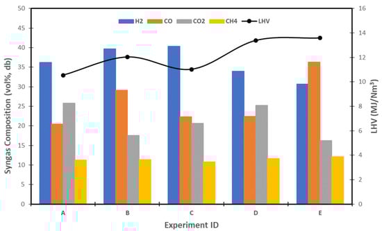
Figure 2.
Experimental results of gas composition and LHV from steam gasification of some woody biomass in a dual fluidised-bed gasifier.
Table 4.
Operating conditions in the steam gasification of some woody biomass in a dual fluidised-bed gasifier.
Since the biomass gasification process aims at the conversion of low heating value biomass to medium calorific value product gases, the heating value of the producer gas is considered another important performance indicator. The low heating value (LHV) of the producer gas, which is highly dependent on the gas composition, ranges from 11–14 MJ/Nm3 for the DFB steam gasification, as illustrated in Figure 2.
Other performance indicators, such as gas yield and cold gas efficiency (CGE), for the steam gasification of woody biomass in pilot-scale DFB gasifiers are reported in previous studies [61,62]. Results from the study of Schmid et al. [61] showed that the yield from gasification of woody biomass at 800 °C was 0.84 Nm3/kg for softwood and 0.91 Nm3/kg for hard wood, with CGE of 63% and 67%, respectively. This is comparable with the experimental results from the study of Zhang and Pang [62], wherein gasification of pine wood at 800 °C generated 0.86 Nm3 of producer gas per kg of dry ash-free biomass with a CGE of 69%.
3.3. Effect of Operating Conditions
Biomass gasification is a complex thermochemical process in which endothermic and exothermic reactions, heat and mass transfer as well as fluid flow occur simultaneously in the gasifier. Operation conditions, such as gasification agent, gasification temperature and steam-to-biomass ratio for steam biomass gasification, significantly influence the overall performance of the gasification system and the producer gas quality.
3.3.1. Gasification Agent
Gasification agents in biomass gasification include pure oxygen, air, CO2, steam, or a combination of them. Air as a gasification agent yields producer gas with a low heating value (4–6 MJ/Nm3), which is much less than that using other gasification agents because of the nitrogen dilution. In contrast, using steam or oxygen or combining steam with oxygen generates producer gas with a heating value of 12–14 MJ/Nm3. Table 5 compares the producer gas LHV and composition as well as gasification temperatures using different gasification agents. Indicator of production costs are also included for the comparison.
Table 5.
Comparison of gasification process using different gasification agents [3].
Pure oxygen is a desirable gasification agent since it produces good quality producer gas with relatively high concentrations of H2 and CO, and much lower tar content. However, using pure oxygen makes the operation very costly and could detrimentally affect the economics of the process. Meanwhile, using carbon dioxide as a gasification agent promotes CO formation and increases the heating value of the producer gas. The downside is the slow reaction rates for chemical reactions involved, thus requiring a longer reaction time.
Steam as a gasification agent can promote hydrogen and CO yields and is thus preferred in biomass gasification to produce gaseous and liquid fuels. It has the potential to produce syngas with high heating values and high hydrogen content. However, the biomass steam gasification reactions, at high temperatures of 700–900 °C, are overall endothermic and require external heat supply [54]. Therefore, steam gasification using dual fluidised-bed gasifiers, as discussed in Section 3.2, has been gaining attention worldwide. Recently, steam gasification is considered one of the most efficient and effective thermochemical processes for hydrogen production from biomass [3,63]. It has been proven viable for both medium-scale and large-scale gasification processes and is considered better than air gasification in terms of gas composition and tar production [63].
3.3.2. Gasification Temperature
The operating temperature of the gasification plays an important role in the final composition of the producer gas, since the equilibrium conditions for the main reactions in the biomass gasification process are a function of temperature. Following Le Chatelier’s principle, higher temperatures favour the product formation in endothermic reactions, while the lower temperatures favour the formation of products in exothermic reactions although the lower temperature results in slow reaction rates. Therefore, the selection of operation temperature of the gasification process must consider the exothermic and endothermic reactions simultaneously as well as the reaction rates, with the aim of high gas yield and high CO and H2 contents in the producer gas [9].
According to previous research [16,31], the producer gas yield, composition, and heating value are most sensitive to the gasification temperature among operating variables. The effect of temperature on hydrogen production in the steam gasification of various biomass feedstock was studied by a number of researchers [23,31,32,58,59,64].
Doherty et al. [31] observed that increasing the temperature in the steam gasification of pine woodchip in a DFB gasifier from 650 to 950 °C can increase the H2 and CO content by 46.65 vol.% and 27.04 vol.%, respectively. At the same time, the contents of CH4 and CO2 are reduced from 44.03 to 1.45 vol.% and from 43.15 to 12.35 vol.%, respectively. It was also noticed in the study that the gasification temperature has less impact on the producer gas composition at gasification temperature over 950 °C and that gasifier temperature of over 1000 °C should be avoided to prevent ash melting.
In another study, by Zhang and Pang, on gasification of pine wood in a DFB system [53], it was found that increasing the operation temperature from 700 to 800 °C increased the H2 content from 22 vol.% to 25 vol.%, while the CO content was increased from 40 vol.% to 42 vol.%, whereas the CO2 content decreased from 18 vol% to 13 vol.%. The CH4 content maintained relatively constant at 14 vol.%. Interestingly, the cold gas efficiency was increased from 62 to 69% with the increase in gasification temperature, while the tar yield was favourably decreased by 12% from 7.56 to 6.67 g/kg dry-ash free biomass.
The same observation regarding the effect of gasifier temperature on producer gas composition was also reported by Zhai et al. [33] who conducted study on steam gasification of pine sawdust. It was found that with an increase in the gasification temperature from 600 to 800 °C, the H2 content increased from 35 vol.% to 38 vol.% and that of CO increased from 10 vol.% to 25 vol.% in the producer gas. Correspondingly, the carbon conversion was increased from 58% to 98%. It was also observed that CO2 content decreased from 20 vol.% to 8 vol.%, while the CH4 content decreased from 7 vol.% to non-detectable low level. Further increase in the gasification temperature above 800 °C showed a noticeably less impact on the producer gas composition.
In summary, high operating temperatures in the biomass steam gasification are favourable in producing gas with high hydrogen content and less heavy tars [14,16]. The CO content and carbon conversion efficiencies also increase with the gasification temperature, while CO2 and CH4 decrease due to the equilibrium shift with temperature increase [33]. Furthermore, the overall producer gas yield increases with an increase in the operation temperature due to the release of more volatiles. Higher temperature favours the producer gas and hydrogen yields, but too high a gasification temperature could lower the LHV of the producer gas [65]. Previous studies show that the optimal temperature for H2 generation in DFB steam gasification is 800–900 °C [13,33,56].
3.3.3. Steam-to-Biomass Ratio
In biomass gasification with steam as the gasification agent, the steam-to-biomass mass ratio (S/B) is another important operating parameter affecting the H2 content in the producer gas. The S/B could influence the input energy requirements and the product gas yield and quality. Studies on the effect of S/B in DFB gasifiers are widely available [24,31,32,59,64].
Doherty et al. [31] observed that varying the S/B from 0.25 to 1.35 resulted in an increase in both H2 and CO2 contents by 25.7 vol.% and 7.27 vol.%, respectively. At the same time, both CO and CH4 contents were dropped by 17.69% and 15.8%, respectively. For DFB biomass steam gasification, an S/B range of 0.5–1.0 was recommended based on a number of studies, since operation at higher S/B requires higher energy for steam generation and showed a detrimental effect on the syngas LHV.
In a study by Zhai et al. [33] on a model simulation of pine wood steam gasification with feeding rate of 1000 kg/h, it was found that with the increase in S/B from 0.06 to 0.3 at a gasification temperature of 800 °C, the H2 yield increased from 35 kmol/h to 48 kmol/h. The carbon conversion rate also showed improvement from 75 to 100% as the S/B was increased, while the CGE decreased slightly from 41.5 to 40.5%.
The same effect of S/B on producer gas composition has been observed in the studies of Huang and Jin [13] and Tavares et al. [9]. In the study of Huang and Jin, the H2 and CO2 contents in the producer gas increased by 6.78 vol.% and 13.74 vol.%, respectively, as the S/B ratio was increased from 0.7 to 2.8. However, the content of CO decreased by 19.52 vol.%, and the content of CH4 decreased by 1.9 vol.%, with the increase in S/B. Similarly, Tavares et al. observed that with the S/B increase from 0.1 to 2.0, the H2 content increased from 35 vol.% to 60 vol.%) and the CO2 content from 5 vol.% to −28 vol.%). However, the CO content decreased from 50 vol.% to 15 vol.% and that of CH4 decreased from 8 vol.% to almost zero.
From these previous research findings, biomass gasification with high S/B values promotes steam reforming and water–gas shift reactions, resulting in increased gas yield, hydrogen yield, and H2 and CO2 concentrations, but reduced CO and CH4 concentrations in the producer gas. Following Le Chatelier’s principle, the higher steam feeding rate favours the steam reforming and water–gas shift reactions towards the product (hydrogen) formation [18,65]. However, excessive steam feeding could cause enthalpy losses due to the heat consumed for steam generation and excessive unreacted steam in the producer gas which results in reduced process efficiencies and low gas quality [49]. Hence, it is ideal to use an optimised steam-to-biomass ratio. Typical S/B used in woody biomass steam gasification processes range from 0.5 to 1.2 [66,67].
4. Producer Gas Processing
The producer gas generated directly from the biomass gasification contains various gaseous species. In addition, the gasification product also contains a minor quantity of unreacted char and ash, as well as a small fraction of heavy molecular weight organic compounds, termed as tar. Hence, further cleaning of the gas to remove tar compounds and contaminant species (NH3, H2S and HCl) is necessary. In addition, further processing of the producer gas to convert the other gaseous species to hydrogen and CO2 and H2 purification are needed to increase the H2 yield and to generate a stream of pure CO2 for reuse. The general hydrogen production process flow for integrated biomass gasification with gas processing is illustrated in Figure 3.
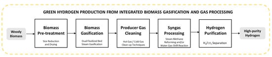
Figure 3.
General process flow of integrated biomass gasification with gas processing for hydrogen production.
4.1. Producer Gas Cleaning
Generally, the gas cleaning techniques are classified as ‘primary’ and ‘secondary’ clean-up methods. The primary or in-situ clean-up refers to the processes that reduce undesirable components in the producer gas within the gasifier, while the secondary clean-up techniques are the processes added in the downstream to clean the producer gas [68]. In addition to the location of the gas cleaning within the process, gas clean-up technologies in the secondary techniques are classified based on the process temperature range and gas cleaning sorbents: the cold gas clean-up or the hot/warm gas clean-up. The downstream gas cleaning can also be categorised as a wet method where solvent is used and a dry method where only solid sorbents or catalysts are used [69].
The cold gas clean-up methods, which are commonly wet processes, are used to remove contaminants from the producer gas at relatively low temperatures (<100 °C). In addition to the wet methods, cold gas clean-up methods can be based on adsorption, filtration and electrostatic precipitators or cyclones. In general, the advantage of cold gas clean-up includes high efficiency of contaminant removal and convenient operation. However, the main disadvantages are the high energy penalty, as the producer gas needs to be cooled down before the cleaning, and the additional cost acquired from the treatment or disposal of the contaminant streams [67,68,69].
In contrast to cold gas clean-up, the hot gas clean-up methods involve the removal of contaminants from the producer gas at high temperatures (>300 °C), such as catalytic tar cracking and contaminant adsorption by using metal oxide materials [68,70]. The main advantage of this technology is that it does not need the gas cooling and reduces waste streams by converting some of the contaminants into compounds which do not cause harm to the environment or may even be used as valuable products. Techniques that employ hot gas clean-up include particulate removal, thermal cracking, catalytic cracking, and steam or dry reforming [69,70].
Experimental and simulation-based studies have been reported to investigate the efficiency of different gas cleaning techniques in reducing the tar content of producer gas from biomass gasification. In the study of Harb et al. [71] and Zhang et al. [72], the oil-based gas washing process (OLGA), which combines a collector with an absorber and a stripper to separate light and heavy tar, was investigated for its tar removal efficiency by process simulation using Aspen Plus. The results of the simulation by Harb et al. using methyl-oleate as the absorbent showed an overall tar removal efficiency of 98.8% for an initial tar concentration of 7098 mg/Nm3 using an oil flow rate of 5500 kg/h at 333 K. While the use of the mixture of soybean oil and N-formylmorpholin at the optimized condition in the study of Zhang et al. showed that the process can reduced the tar content of producer gas from 9030 mg/Nm3 to below 30 mg/Nm3.
Hai et al. [73], examined novel tar-reducing techniques using a char bed, woodchip bed and mop fan connected to the end of the cyclone in a biomass gasifier. The bio-char was found to be unsuitable for tar removal due to the burning of bed, while the woodchip showed 29% tar reduction efficiency. The use of a mop fan with and without water spray presented a tar removal efficiency of 89.6% and 60%, respectively.
Pranolo et al. [74] assessed another gas cleaning system which consists of scrubber, elutriator pipe, and shell-and-tube heat exchanger to produce low-tar-content producer gas from the fixed-bed air gasification of palm kernel shell and mahogany fruit shell. The highest tar removal efficiency demonstrated by the system for the palm kernel shell and fruit shell were 70.84% and 18.72%, respectively.
In another study, by Pallozi et al. [75], the efficiency of a tar removal system consisting of a dolomite bed reactor and vegetable oil scrubber for gas conditioning and gas cleaning, respectively, was investigated. The results showed that the combination of the gas conditioning and cleaning system was better than the separate usage of the dolomite bed and oil scrubber. The simple cleaning system which only uses the oil scrubber was not desirable, since tar removal efficiency immediately dropped down only after 1.5 h of operation, whereas the combined system showed high tar conversion even after 12 h of operation. Meanwhile, the use of the dolomite bed alone undesirably showed very high gas dew point.
4.2. Producer Gas Processing: Steam Methane Reforming
The producer gas directly from the biomass gasification contains 5–15 vol.% CH4 and other light hydrocarbons, depending on the gasification agent, biomass species, gasification temperature and gasifier type. Steam reforming is an endothermic reaction which converts methane and other hydrocarbons to H2 and CO. Generally, the steam reforming reaction has been used for hydrogen production from methane, ethane, methanol, ethanol, acetone, and other higher hydrocarbons [76]. It is currently the leading industrial process of producing hydrogen from fossil fuels. However, it is recently gaining attention among researchers as a pathway to produce syngas from biogas [77,78,79]. Moreover, it has been proposed for hydrogen production from biomass gasification to reform tar and methane in the producer gas and enrich the hydrogen content in the gas stream [80,81,82,83,84].
Steam methane reforming (SMR), which focuses on hydrogen production from methane, is described by reaction (R8 in Table 3), wherein one mole of H2O theoretically reacts with one mole of CH4 to produce three moles of hydrogen and one mole of CO. In actual operation, the reforming reaction is carried out with excess feeding steam, usually at a steam-to-carbon-molar ratio of 2.5–3, to enhance complete reaction and to reduce catalyst deactivation by coke deposition. A thermodynamic study of the reforming reaction shows that CH4 conversion and chemical kinetics are favourable at high temperatures of 700–900 °C [85]. Catalysts used in steam reforming include non-precious metals, typically Ni-based, and noble metal-based ones such as ruthenium, rhodium, palladium, and platinum [86].
Experimental studies have been reported to investigate the steam reforming of the producer gas from biomass gasification [28,80,81,87]. In the study by Savuto et al. [80], producer gas with a composition of 27.03 vol.% H2, 26.74 vol.% CO, 38.29 vol.% CO2 and 7.87 vol.% CH4 from biomass gasification was processed through steam reforming using a Ni/Mayenite catalyst at 800 °C to evaluate the efficiency of SMR on tar and CH4 conversion. The results from the study showed that SMR increased the H2 and CO concentrations to 31–35 vol.% and 25–30 vol.%, respectively. In contrast, the CO2 and CH4 concentrations decreased to 30–36 vol.% and 0–6.5 vol.%, respectively. Methane presented a conversion rate of 20–30%. At the same time, benzene and toluene were converted with conversion rates of 60–80% and more than 90%, respectively. Moreover, the heavier tars analysed, including naphthalene, pyrene, fluorene, anthracene, and phenanthrene, showed 100% conversion rates.
In another study, by Ngo et al. [88], producer gas from the gasification of rice straw underwent steam reforming at 400 °C using a zeolite catalyst to enhance hydrogen generation and minimize tar yield. The H2 and CO contents of the syngas after SMR increased from 7.31 vol.% to 14.57 vol.% and 8.03 vol.% to 17.34 vol.%, respectively, while tar removal efficiency was observed at 70–90%.
It has been evident from these studies that integrating downstream steam reforming with biomass gasification can significantly increase the hydrogen content in the producer gas through the conversion of methane and other hydrocarbon species. In particular, this strategy could promote a more appropriate H2-to-CO ratio for downstream water–gas shift reaction and an overall increase in cold gas efficiency and calorific value for the syngas.
4.3. Producer Gas Processing: Water–Gas Shift Reaction
After the steam reforming reaction, the hydrogen content in the producer gas has been increased; however, the gas still contains CO, which can be further converted to H2 and CO2 through the water–gas shift (WGS) reaction. The WGS reaction has been widely used for hydrogen production from natural gas and for syngas conditioning to adjust the H2-to-CO ratio. It is commonly employed for downstream syngas conditioning in hydrogen production processes from fossil fuel reforming and biomass gasification. The WGS reaction is a reversible redox-type reaction, as presented in Table 3 (R9) [25].
WGS reaction operation is typically performed in two-stage reactors, the first stage at high temperatures and the second stage at low temperatures. Since the reaction is exothermic, the lower temperature favours the formation of product, namely, hydrogen and CO2. However, the reaction rate is low at low temperatures. Therefore, the high-temperature water–gas shift reaction (HT-WGS) aims to achieve high reaction rates, whereas the subsequent low-temperature water–gas shift reaction (LT-WGS) promotes the conversion of the reactants (CO). The HT-WGS is accomplished at 310–450 °C and 25–35 bar with Fe and Cu as catalysts promoted by Ni, Cr, Zn, Al, Mn, Co, and Ce. On the other hand, the LT-WGS is performed at 200–250 °C using Cu-Zn, CU-Mn, and Cu-Fe catalysts promoted by Pd, Pt, and Al [25,89,90].
A number of studies have been reported in the literature to investigate the WGS reaction of producer gas from biomass gasification to increase the hydrogen content by converting CO in the gas [86,91,92]. In the study of Patra et al. [91], the effect of WGS reaction temperature on CO conversion was experimentally investigated for a typical producer gas from biomass gasification with air as the gasification agent, which contained 15.95 vol.% H2, 15.74 vol.% CO, 12.41 vol.% CO2, 5 vol.% CH4, and 50.90 vol.% N2. Evaluation of the process under various WGS reaction temperatures (300 °C, 325 °C, 350 °C, and 375 °C) at a constant steam-to-CO ratio of 8 showed that CO conversion increased from 53.88% at 300 °C to a maximum value of 78.99% at 375 °C. With an increase in the reaction temperature from 300 to 375 °C, H2 and CO2 contents increased from 24.21 vol.% to 27.29 vol.% and 21.59 vol.% to 24.65 vol.%, respectively, while the CO concentration decreased from 7.35 vol.% to 3.35 vol.%.
In another study, by Chianese et al. [92], biomass-derived tar-rich producer gas was processed through high-temperature WGS reaction at 350–450 °C using an iron/chromium industrial catalyst in a pilot plant. The producer gas treated had a composition of 35–45% H2, 20–30 vol.% CO, 15–25 vol.% CO2, 8–12 vol.% CH4, and 1–3 vol.% N2. The study showed that an increase in the WGS temperature increases CO conversion and H2 concentration. The highest H2 concentration enhancement of the producer gas from 30 vol.% to 45 vol.% was observed at a WGS reaction temperature of 450 °C with CO conversion of 83%.
These studies clearly show the effectiveness of the WGS reaction in adjusting the H2-to-CO ratio by enriching the H2 content and reducing the CO content of the producer gas from biomass gasification. Implementing either low-temperature or combined two-stage WGS reactions depends on the initial composition of the producer gas and the target H2/CO ratio to meet the downstream application requirements.
4.4. Separation of H2 and CO2
Integrating CO2 capture into the hydrogen production process requires a supplementary gas separation technique after the syngas production and gas processing to acquire high-purity hydrogen for transport and sufficiently high-purity CO2 for storage and reuse. At present, pressure swing adsorption (PSA) is the widely utilized method for hydrogen purification, while absorption with special solvents is the most established technology for CO2 capture [93].
In PSA systems for hydrogen purification, there are normally two steps: an adsorption step with high pressure and low temperature, and a desorption step with low pressure and high temperature. In the adsorption step, CO2 and other impurities are removed through adsorption by solid sorbent, and thus, the purified hydrogen product is recovered in the effluent of the adsorption. During the subsequent desorption step, adsorbed CO2 is released in the tail gas stream. PSA cycles are operated to purify both the H2 and the CO2 streams and involve a series of adsorption, co-current and counter-current depressurisation, purging, and counter-current pressurisation. A detailed description of the PSA process for hydrogen purification together with the methods to improve H2 PSA performance is available elsewhere [94]. Typical adsorbents for hydrogen purification include activated carbon, silica gel, zeolite, alumina, and metal-organic frameworks (MOF). PSA technology can produce 98–99.9999 vol.% pure H2 with up to 95% H2 recovery [93].
For the H2/CO2 separation, gas absorption and desorption technology is also commonly used with integrated scrubber and stripper units. In the scrubber, CO2 removal from the gas mixture occurs using a liquid solvent that selectively absorbs CO2 at high pressure and low temperature. At the same time, the CO2-loaded solvent is pumped into a stripper where CO2 desorption occurs at low pressure and increased temperatures. In this way, the solvent can be regenerated for cyclic use [95,96], and two gas streams can be generated, pure H2 from the scrubber and pure CO2 from the stripper. The efficiency and purity of the hydrogen and CO2 are also affected by pressure and temperature.
Aside from absorption and adsorption, membrane separation and cryogenic distillation are emerging technologies for hydrogen purification and CO2 capture [97,98,99,100]. Membrane separation uses selective barriers that allow specific components to pass through. The permeate side contains the elements that pass through the membrane, while the retentate side comprises the impermeable species. Hydrogen-selective membranes yield high-purity hydrogen permeate and an impure CO2 retentate, while CO2 selective membranes produce CO2-rich permeate and CO2-depleted retentate [93].
Cryogenic or low-temperature technologies take advantage of the difference in the condensation and desublimation points of the different components of a gas mixture to separate them. Hydrogen purification requires lowering the gas mixture temperature to cryogenic temperatures of CO2 (<−150 °C at 1.013 bar) to allow the selective condensation of CO2 leaving the hydrogen in the gas phase. In the meantime, the CO2 condensate can be separated [93].
Moreover, process intensification techniques are under development, which combines syngas production and gas separation to make the process more efficient by shifting the equilibrium reactions towards the desired products. This process intensification technologies include membrane reactors, chemical looping, and sorption-enhanced hydrogen production [101,102,103,104,105].
There are also emerging technologies which combine hydrogen purification and CO2 capture. Streb et al. [98,106] proposed a new process based on vacuum pressure swing adsorption (VPSA) cycles for the co-production of high purity CO2 and H2 with high recovery from a ternary feed stream. The developed VPSA cycle comprised pressure equalisation, product purge, and product pressurisation steps which ran continuously in several columns with different adsorbent materials. Modelling and optimisation of the process showed that it can purify CO2 up to 95 vol.% with greater than 90% recovery while co-producing hydrogen with the same specifications.
5. Simulation-Based Modelling of Biomass Gasification
Simulation-based studies or mathematical modelling of biomass gasification provide an important and effective tool to better understand the gasification process and to evaluate the influence of operating parameters on gasification performance. Although the experimental route remains the most reliable, this approach induces high costs and difficulties in reproducibility as well as limitations in operating conditions such as very high temperatures. Simulation-based and mathematical modelling, with a rigorously theoretical basis and validation, can serve as a low-cost and effective method for understanding and identifying operational limits, and optimising the operation parameters [4,5].
5.1. Simulation of Biomass Gasification with Aspen Plus
Aspen Plus is a process simulation software widely employed in oil, gas, and chemical industries to generate process flowsheets. The program uses unit operation blocks such as reactors, columns, pumps, and heaters linked by material and energy streams, and has a built-in database for physical properties. The software has integrated models for conventional processes and equipment such as gas turbines, heaters, and cyclone separators. However, it lacks a model for the gasification process. Therefore, modelling the gasification process in Aspen Plus involves breaking down the whole process into several sub-units. In this approach, reactors and separators are used in the flowsheet to represent each zone (drying and pyrolysis, partial oxidation, and gasification) in a typical gasifier. Like any modelling approach, it is critical for the developed models to be validated by comparison of the model predictions with available experimental data [52].
Previous modelling studies have used Penge-Robinson (PR) [11,24,33], Penge-Robinson equation with Boston-Mathias alpha function (PR-BM) [6,12,13,14,17,31,107,108], IDEAL [22], Redlich Kwong-Soave with Boston-Mathias alpha function (RKS-BM) [9,109], and Redlich Kwong-Aspen (RK-Aspen) [21,23] to calculate the physical properties of the conventional elements and compounds involved in the biomass gasification. Meanwhile, HCOALGEN and DCOALIGT models are used to estimate the enthalpy and density of the non-conventional components such as biomass and ash, respectively [6,7,8,9]. Since Aspen Plus lacks the properties of non-conventional components, an RYield reactor is commonly used to decompose the biomass into constituent elements (C, H, O, N, S) based on its ultimate analysis [52,110].
Mutlu et al. [110] proposed a general gasification flowsheet in Aspen Plus as shown in Figure 4. As presented in the study, the biomass first enters a mixer with a drying medium. In this way, the first gasification zone, which is the drying stage, is modelled in an RStoic block with a Fortran subroutine. Following this is the decomposition of the biomass in an RYield reactor to convert it to its conventional components through thermal devolatilisation. Depending on the modelling approach, the components together with the gasification agent, which can be air, oxygen or steam, enter either RGibbs, RCSTR, or RPlug reactor/s for the gasification stage. Lastly, the partial combustion stage with either air or oxygen is modelled using an RStoic reactor. The final gas products flow out of the gasifier and then through a cyclone in which fine solid particles (ash and char) are removed. Depending on the objectives or complexity of the overall process, this general flowsheet may contain additional blocks or supplementary user-defined blocks written in Excel or created using Fortran subroutines and integrated into the Aspen Plus flowsheet.
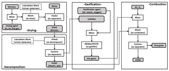
Figure 4.
General Aspen Plus process flowsheet of biomass gasification (Grey boxes indicate compounds) [110]. (Reprinted from Chemical Engineering & Technology, Vol. 43 (9), O.C. Mutlu and T. Zeng, Challenges and Opportunities of Modeling Biomass Gasification in Aspen Plus: A Review, pp. 1674-1689, copyright (2020), under Creative Commons Attribution–Non-Commercial License.)
For modelling the chemical reactions in the biomass gasification process, two fundamental approaches are used in Aspen Plus: equilibrium modelling and kinetic modelling. The subsequent subsections discuss these modelling approaches in detail. As an overview, non-stoichiometric equilibrium modelling, which assumes that the components are allowed to react for an infinite period, is carried out using the RGibbs block. The RGibbs block uses minimisation of the system’s Gibbs free energy. On the other hand, kinetic modelling predicts actual products from non-ideal (non-equilibrium) reactors after allowing the gases in the gasifier to react for a limited time or in a finite volume, and this can be simulated by using external Fortran subroutines to integrate bed hydrodynamics with reaction kinetics. Process blocks for kinetic modelling include RCSTR and RPlug reactors.
Several Aspen Plus-based thermodynamic equilibrium and kinetic models have been published in the past decade for gasification of woody biomass with steam or combined air and steam as the gasification agent. An overview on the statistic of these models is presented in Figure 5 in terms of the modelling approach and the target gasifier configuration for applications. From this data, it can be observed that equilibrium models are generally applied to both fixed bed and fluidized bed type gasifiers. Meanwhile, most of the kinetic modelling approach is for fluidized bed gasifiers including both circulating and bubbling type as well as dual fluidized bed gasifiers.
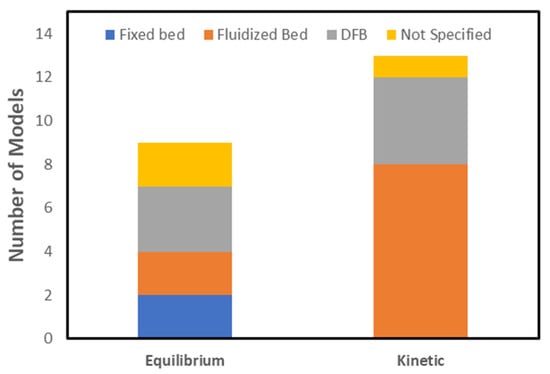
Figure 5.
Aspen Plus models published in the past decade for gasification of woody biomass with steam or combined air and steam as the gasification agent.
Since this article focuses on DFB steam gasification of woody biomass, relevant equilibrium and kinetic modelling studies for the steam gasification of different woody biomass in the DFB gasifiers are presented in Table 6 and discussed in detail in the succeeding sections. Table 6 presents the model predicted gas composition, LHV of the dry producer gas and model accuracy assessment based on the relative error of the model’s prediction with experimental data are presented in Figure 6. The assumptions considered in the presented models are summarized in Table 7.
Table 6.
Summary of related literature on the Aspen Plus modelling of woody biomass steam gasification in DFB gasifiers.
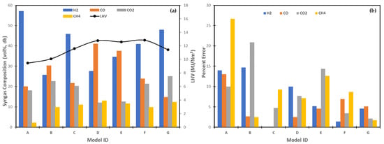
Figure 6.
Predicted producer gas composition and LHV (a), and relative errors of simulation models (b) for the steam gasification of woody biomass in a dual fluidised-bed gasifier. The model IDs are given in Table 6.
Table 7.
Assumptions made in the Aspen Plus simulation of biomass steam gasification.
5.2. Thermodynamic Equilibrium Models
The thermodynamic equilibrium approach predicts the product gas composition based on the equilibrium state. It is convenient and straightforward since it only considers the reactions involved and does not consider the reaction rates. It is useful to predict the trends of impacts of operation conditions, although this approach induces significant errors in predicting the producer gas composition. However, its application can be applied to fast reactions such as in high-temperature gasification, whereas the application at lower-temperature gasification is inappropriate where the reaction rates are relatively low [4,5]. Nevertheless, thermodynamic equilibrium modelling has been reported in several studies [7,9,108].
Equilibrium models are classified into stoichiometric and nonstoichiometric models, which differ in applying the equilibrium status. The stoichiometric approach computes equilibrium to preselected reactions, while the nonstoichiometric method minimizes Gibb’s free energy. The nonstoichiometric approach is considered more complex than the stoichiometric approach, yet the nonstoichiometric modelling is considered more advantageous because it is unnecessary to select and assess the reactions [5].
According to the review article of Safarian et al. [4], the stoichiometric models and nonstoichiometric models yield identical predictions in most cases. Therefore, another categorisation has been introduced by Safarian et al. based on factors that significantly affect the yield and product composition [4]: Eq-single and Eq-separate. The Eq-single modelling simulates the gasification stage reaction—combustion and reduction—as a single global equilibrium. In contrast, the Eq-separate models the char combustion as a distinct equilibrium in a different reactor from the volatile matter and un-combusted char reduction. According to the authors, the Eq-single method is sufficient for equilibrium model simulations that aim to ascertain the thermodynamic limits of the process. However, the Eq-separate approach is more appropriate for predicting the actual output of a non-ideal gasifier as it considers targeted empirical adjustments [4].
Thermodynamic modelling has been widely applied in modelling biomass gasification in fixed-bed gasifiers, specifically downdraft gasifiers [6,7,8,9,10,11,12,13,14]. Although this approach may be applied to any type of gasifier, the assumption of reaction reaching equilibrium induces errors in the prediction of gas composition. The errors vary with the reaction rates and the gasifier types. The better accuracy of this approach with downdraft gasifiers can be associated with the fact that near real equilibrium can be attained in a relatively brief period in downdraft gasifiers since both pyrolysis and gasification products are forced to the high-temperature oxidation zone in this type of gasifier configuration. Therefore, the use of this approach to model gasification in other types of gasifiers, specifically fluidized bed type, requires additional considerations to improve the model accuracy. Additional techniques employed in relevant studies include the incorporation of empirical correlations and the use of the function of temperature to restrict the equilibrium of selected reactions based on available experimental data [11,32,108].
For instance, in the study of Liao et al. [32], an equilibrium model for the gasification of woody biomass in a DFB gasifier was proposed, and subsequently, a semi-empirical model was developed to improve the accuracy of the model predictions based on the experimental data. Following the typical gasification modelling in Aspen Plus, the model was composed of three main sections: pyrolysis zone, gasification zone, and combustion zone. For the equilibrium model, the gasification zone was simulated using an RGibbs block based on the minimisation of Gibbs free energy. In contrast, for the semi-empirical model, the equilibrium calculation of some of the gasification reactions were restricted using known producer gas composition. Specifically, the equilibrium restrictions were applied to the reverse water–gas shift and hydrogenating reactions to match the experimental measurements for CO and CH4. A simulation of the equilibrium model showed over-prediction of hydrogen and under-prediction of methane, both with 100% error. Restriction of the equilibrium of some reactions improved the equilibrium model prediction with errors below 14.7% for H2 prediction and 2.5% for CH4 prediction, respectively.
In another study by Doherty et al. [31], the same method of equilibrium restriction for some reactions was employed in modelling the steam gasification of wood chip in a DFB gasifier. Initially, the equilibrium model was prepared by Gibbs free energy minimisation. The resulting equilibrium model was then calibrated by restricting the steam methane reforming and water–gas shift reactions using the temperature difference approach values of −265 °C and −90 °C, respectively. The temperature difference approach values are defined as the difference between the temperature at which the chemical equilibrium is calculated and the actual reactor temperature. These temperature difference values can be specified in the RGibbs reactor setting in the Aspen Plus flowsheet. The restricted equilibrium model showed good agreement with pilot plant data with errors below 9.26% for CH4 prediction, 4.75% for CO2 prediction, and virtually 0% for H2 and CO predictions. The validated model was used to investigate the effect of gasification temperature, biomass moisture, S/B, air–fuel ratio, and air and steam temperature on the product gas quality.
In terms of the producer gas concentration in equilibrium model predictions, it has been observed that the formation of methane was commonly underestimated [9,12,14,32]. This was commonly attributed to the assumption of complete conversion of methane into hydrogen and carbon monoxide during the pyrolysis stage and the slow methane reforming reaction in the gasification stage [12,108]. To improve the equilibrium model, some studies introduced a more detailed pyrolysis model and removal of CH4 in the combustion-gasification stage bypassing it to the gasifier outlet [11]. Another approach is to restrict the equilibrium of reactions involving methane similar to those studies discussed above. Meanwhile, agreement of equilibrium model predictions for H2, CO, and CO2 concentrations are in closer agreement with experimental data (<5% error) than that of methane [4,12,31].
Another commonly identified contributor to the prediction errors is the exclusion of cracking and reforming reactions of tar compounds in the model [111]. This is understandable since tar, in the first place, is a non-equilibrium product. Although more advanced equilibrium models have already considered the tar formation by introducing empirical correlations, the tar was either considered as an inert compound or the tar yield was not incorporated in the validation studies [34,110].
5.3. Kinetic Models
Kinetic models predict the product yield and gas composition under non-equilibrium conditions. The kinetic modelling approach is based on actual reaction rates under given conditions as a function of reaction time; therefore, the predicted results are from non-ideal reactors after allowing the gases in the gasifier to react for a finite period or in a limited volume. It incorporates the gasification reaction kinetics and may include the hydrodynamics of the gasifier. The reaction kinetics predict the product yield and distribution under given operating conditions, while reactor hydrodynamics encompasses comprehension of the physical mixing process depending on the gasifier type. Kinetic models can estimate product composition and temperature profiles throughout the different gasifier zones. Compared to the equilibrium models, the kinetic models are more suitable and accurate over a wide range of gasification operation conditions, particularly for low gasification temperatures.
There are several means to classify kinetic models. One classification depends on the model’s sophistication and accuracy based on the reactor hydrodynamics: zero-dimensional (stirred tank reactor), one-dimensional (plug flow), two-dimensional, and three-dimensional. Since kinetic models consider the gas–solid contacting mechanism, the models can also be classified based on the gasifier type: fixed-bed, fluidised-bed, or entrained-flow [5]. Finally, kinetic models are also classified based on the degree of reaction kinetics application: total kinetic, semi-kinetic, and the combination of kinetic, equilibrium, and empirical adjustments [4].
Kinetic modelling has been applied to different types of gasifiers. It has limited applications with fixed-bed gasifiers [111] and entrained-flow gasifiers [112], but widely applied in fluidised-type gasifiers including bubbling fluidised-bed [16,17,18,19,21], circulating fluidised-bed [15] and dual fluidised-bed [23,24,60,64] gasifiers. Generally, the kinetics modelling studies may also consider the hydrodynamics of the gasification process to evaluate the effect of the design of the gasifier on the extent of heat and mass transfer that could influence the kinetics of the reactions [21,22,24]. This is particularly true in the case of fluidised-bed gasifiers since the complex solid–gas contact patterns in this type of gasifier significantly affect the large deviations from ideal equilibrium compositions. Thus, the complexity of the model has been observed to increase with increasing complexity in the configuration of the gasifiers [5].
As presented in Table 6, there are available kinetic models in the literature for the steam gasification of woody biomass in dual fluidised-bed gasifiers [23,24,60,64]. For instance, Abdelouahed et al. [23] developed a model for the gasification of woody biomass in a DFB gasifier considering two different DFB technologies including the Tunzini Nessi Equipment Companies (TNEE) and Battelle High Throughput Gasification Process (FERCO). The study focused on the chemical mechanisms in the gasifier rather than the bed hydrodynamics. To account for this, a pyrolysis correlation was incorporated into the model to calculate the mass yields of the pyrolysis products consisting of permanent gases, water, tar species, and char. Moreover, a semi-kinetic mechanism was employed to model the char gasification, combustion, and secondary reactions comprising the homogeneous gas-phase reactions and heterogeneous catalytic conversion over char of CH4 and lumped tar species. The detailed modelling of the pyrolysis stage, including primary and secondary reactions, resulted in a close agreement of the model predictions with experimental data for methane at 7% error. However, the model under-predicted the CO2 concentration by 40% and over-predicted the CO concentration by 20%, respectively. These results led to the detailed evaluation of the rate laws for the water–gas shift reaction. Consequently, optimisation of the WGS reaction constant yielded better predictions for CO, CO2, and H2 with errors less than 3%, 8%, and 10%, respectively.
Another study that modelled the steam gasification of wood pellets in a DFB gasifier was conducted by Yan et al. [24]. In the study, a one-dimensional model incorporating both hydrodynamics and kinetic processes was developed in Aspen Plus. In the model, the riser (combustor), which comprised a series of CSTRs, was represented separately from the bubbling fluidised bed, which was then divided into a high-density bed region and a low-density freeboard region. The high-density bed region was modelled as a series of CSTRs and PFRs to represent the dense (emulsion) phase and the dilute (bubble) phase of the region, respectively, with heat and mass transfer between the two phases. Meanwhile, the freeboard region was modelled as another series of CSTRs. Hydrodynamic and kinetic calculations were coupled in each stage using external FORTRAN subroutines. The model predictions showed close agreement with experimental data from the literature with errors less than 5% for H2 and CO, and less than 15% for CO2 and CH4. The model allowed the prediction of gas concentrations, temperature, and hydrodynamic profiles along the height of the BFB.
Meanwhile, in a recent study by Rashidi et al. [60], a kinetic model was developed with detailed estimation of char and tar yields and gas compositions for the steam gasification of beech wood in a DFB gasifier. The study introduced a methodology to predict pyrolysis yields by combining experimental data with a numerical algorithm. Once pyrolytic yields were established, the kinetics of selected gasification reactions were modelled in an external FORTRAN subroutine and linked to Aspen Plus. Lastly, post-pyrolysis tar conversion in the gasifier via thermal cracking and steam reforming was modelled using semi-empirical relations between S/B and tar conversion. A comparison of the model predictions with experimental data from a pilot gasification plant at a S/B of 0.88 showed close agreement with errors of 1.4%, 6.9%, 3.5%, and 8.7% for H2, CO, CO2, and CH4, respectively.
In summary, kinetic models consider actual reaction rates at different temperatures and, thus, are more accurate than the equilibrium models, as can be observed in Figure 6. However, different kinetic modelling approaches require varying degrees of computational complexity depending on the desired outputs of the model. More sophisticated models may require a more detailed analysis of the system which entails the incorporation of more detailed kinetics and/or hydrodynamics. For instance, some studies include the detailed temperature-dependent modelling of the pyrolysis stage using empirical equations to better describe the distribution of pyrolysis products [23,24,113]. Meanwhile, results from some studies showed that defining tar and its kinetics significantly improves model performance and accuracy [19,113]. However, it should be noted that although the coupling of kinetic with transport parameters results in more complex models with potentially better accuracy, the consideration of more specific transport parameters limits the applicability of the resulting model to a specific type of plant [4].
5.4. Gasification with Subsequent Producer Gas Processing Models
Process simulation-based models for biomass gasification in Aspen Plus using either the thermodynamic equilibrium or kinetic modelling approach have been studied by several researchers, as presented in the previous section. However, the literature for simulation models for the integration of the biomass gasification with subsequent gas processing is limited, particularly for woody biomass. Relevant studies that use Aspen Plus simulation to evaluate the effect of integrating downstream gas processing with biomass gasification on the quality of the syngas are presented in Table 8.
Table 8.
Integrated Aspen Plus models of biomass gasification with subsequent gas processing.
From the studies presented in Table 8, it can be observed that biomass gasification can be coupled with various producer gas cleaning and gas processing technologies depending on the desired final syngas composition and application. First, biomass gasification is modelled using either the thermodynamic or kinetic modelling approach and predictions of the resulting model are validated using experimental data. After which, the producer gas from the gasification process is cleaned via cold and/or hot gas cleaning techniques, such as cyclone separation or scrubbing [114] and tar reforming or cracking [25,26]. Modelling of cleaning techniques, such as cyclone separation and scrubbing, can be easily performed in Aspen Plus since the software has integrated models for such conventional processes. Meanwhile, tar reforming can be modelled using either the thermodynamic equilibrium approach based on the minimisation of Gibbs free energy of tar reforming reactions or the kinetic approach in case the kinetics of the decomposition of the tar components are known.
After the removal of impurities such as ash, unreacted char, tar, and other contaminants, the hydrogen content of the syngas is then increased further through the conversion of methane to hydrogen and CO by SMR [28], which is converted to H2 and CO2 in the following WGS reactor [25,27,35,114]. From the studies presented in Table 8, it is evident that the H2 improvement of the syngas is predominantly accomplished via the WGS reaction.
Modelling the syngas processing stage can be considered relatively simple compared to the modelling of the gasification process since it entails fewer reactions. Thus, simulation of the SMR process and WGS reaction can be performed separately in a single reactor. The choice of the reactor will depend on the chosen modelling approach if either equilibrium or kinetic.
From the above discussion, after the gas processing through SMR and WGS reactions, the syngas consists of only H2 and CO2 H2. Therefore, it needs separation and purification to produce high-purity hydrogen as the target product and CO2 for storage and reuse. In the presented studies, the syngas purification and separation processes employed include chemical absorption [44], pressure swing adsorption [25,26,35] and membrane separation. Similarly to the gas processing, modelling of these processes can be easily performed in Aspen Plus, since the software has integrated models for such conventional processes. Experimental results relevant to the process, such as CO2 removal efficiency, can be incorporated into the model.
Puig-Gamero et al. [26] simulated hydrogen production from the gasification of pinewood with producer gas cleaning and integration with methanol synthesis to perform sensitivity analysis. The simulation included the steam gasification of the biomass, tar reforming and pressure swing adsorption for gas cleaning, and methanol synthesis. Variations of the gasification temperature from 800 to 1000 °C and S/B ratio from 0.5 to 1.0 showed that tar production can be prevented by increasing the temperature and steam flow rate. Meanwhile, for the tar reforming, tar conversion was observed to be complete at 900 to 1000 °C. At 800 °C, tar conversion was enhanced with an increase in the S/B ratio. Finally, the integration of the PSA with the gasification and gas cleaning enabled 30% CO2 capture and 95% CH4 conversion, respectively.
In the study of Pala et al. [27], steam gasification of different biomass feedstock with subsequent producer gas adjustment was simulated and modelled in Aspen Plus. The study evaluated the effect of operating parameters in the gasifier and water–gas shift reactor on the syngas yield and composition. The water–gas shift reaction was used to adjust the H2-to-CO ratio of the producer gas from 1.37 to 2.16, thereby meeting the two ratio requirements of the Fischer-Tropsh synthesis. The WGS reaction, favoured in the temperature range of 250–400 °C, was used to condition the producer gas from the steam gasification of wood residues, woodchips, and pine sawdust.
Babatabar and Saidi [25] developed a comprehensive model which integrated the steam gasification of corn cob, wood residue, and rice husk with tar reforming, HT-WGS and LT-WGS, and PSA. The model was used to investigate the effect of gasification temperature, WGS temperature, and S/B ratio on the hydrogen yield, CO conversion, and product composition. The results of the study showed that the maximum hydrogen concentration can be achieved at the high S/B ratio of 1.2 in the gasifier and the WGS reactor, and the low WGS reaction temperature of 300 °C. Meanwhile, the optimum value for the gasification temperature was found to be 800 °C.
In another study, Li et al. [28] investigated the integration of methane tri-reforming (MTR) as a conditioning process for the producer gas in corn straw gasification. The tri-reforming process comprised the three methods to reform methane and increase hydrogen yield. These included steam methane reforming (SMR), CO2 reforming of methane (CDR), and methane partial oxidation (MPO). The results of the study showed that the energy consumption of the system with MTR was reduced by 3.09%, and the energy efficiency was increased by 17.08% in comparison with the system without MTR. The study concluded that incorporation of the MTR process with biomass gasification can lead to the development of a hydrogen production technology with high energy efficiencies.
Meanwhile, Bach et al. [44] evaluated the performance of spruce wood steam gasification in a DFB gasifier with CO2 capture by monoethanolamine (MEA) absorption as the post-treatment process. It was observed in the study that absorption with MEA offers 83% CO2 removal efficiency. Consequently, the H2 concentration and heating value of the product gas were increased by 26% and 27%, respectively.
Interest in modelling the biomass gasification with subsequent gas processing has also been observed with non-woody biomass. For instance, Meramo-Hurtado et al. [114] modelled hydrogen production from gasification of cassava and rice waste. The process involved five main stages: biomass drying, air gasification, gas cleaning, WGS reaction, and CO2 capture using membrane technology. The process showed that the H2 concentration of the producer gas can be increased from 25 vol.% to 55 vol.% after gas cleaning by cyclone separation and water scrubbing, and this can be further increased to 68 vol.% after WGS reaction. Finally, the purity of the final H2 product of 97 vol.% was achieved by membrane separation of CO2 and H2. Hence, the study concluded that the cleaning technologies introduced in the process design have been beneficial. The authors claimed that the overall process had lower rates of environmental impacts compared to other technologies examined in their study [114].
Comprehensive simulation studies were reported to integrate biomass gasification with gas cleaning and gas processing, which provide valuable insight into the overall performance of biomass-based hydrogen production technologies. From these studies, it has been observed that producer gas cleaning processes, such as tar reforming, cyclone separation, and scrubbing, can be more beneficial with air gasification using fixed-bed or entrained-flow gasifiers than with steam gasification in DFB gasifiers. Since producer gas from air gasification is commonly diluted with N2 and other combustion gas products, the producer gas from such gasification processes showed more evidence of improvement in H2 concentration after gas cleaning [114]. Meanwhile, since steam gasification using a DFB gasifier generates producer gas with an H2 concentration that can be as high as 55 vol.%, the effect of gas cleaning, particularly tar reforming, has been more evident in the increase in CO concentration rather than the H2 concentration [26]. Moreover, the accuracy of the gasification model, such as the consideration or negligence of tar formation, would play a critical role in the determination of the necessary gas cleaning process.
On the other hand, syngas processing of steam methane reforming and water–gas shift reaction could efficiently improve the hydrogen concentration in the syngas by up to 25% [27,28]. However, among the two producer gas processing techniques, WGS reaction is more commonly employed in comprehensive models. Thus, SMR as a gas processing technique to convert CH4 in the syngas to H2 and CO needs to be future investigated in the modelling studies.
Finally, the introduction of H2 and CO2 separation technologies, such as membrane separation, chemical absorption, and pressure swing adsorption, has been a crucial step in achieving a high purity H2 stream. The introduction of such technologies remove CO2 from the syngas, thus reducing the CO2 concentration in the syngas from 25 vol.% to less than 5 vol.% [44]. In addition, the introduction of syngas purification with CO2 capture from an environmental viewpoint could achieve the low carbon emission through the biomass gasification pathway for hydrogen production [114].
6. Techno-Economic Assessment of Biomass Gasification
The implementation of biomass to hydrogen technologies significantly depends on their cost-competitiveness with existing technologies in addition to the consideration of process efficiency and other performance factors. Economic indicators commonly used in the techno-economic studies of biomass gasification for hydrogen production include capital investment (CAPEX), operational costs (OPEX), total capital investment (TCI), production cost (PC), levelized cost of hydrogen production (LCoH), break-even price (BEP), net present value (NPV), internal rate of return (IRR), and payback period (PP) [29,30,35,38,115].
In general, there are two approaches in the conduct of techno-economic studies found from the literature. The first approach involves the assessment of technical and economic performance indicators from previous studies followed by economic comparison after adjustments in inflation rates and currency conversion, if necessary [36,116]. The second approach entails the standardized simulation of the processes to be compared using Aspen Plus or Aspen HYSYS to generate mass and energy balances followed by investment and production cost estimation [30,35,38]. An overview of selected studies that evaluated the techno-economics of biomass gasification for hydrogen production is presented in Table 9.
Table 9.
Overview of techno-economics studies on biomass gasification.
Several studies evaluated and compared the techno-economic performance of hydrogen production pathways from biomass gasification against conventional sources [30,35,38]. In the study of Wang et al. [35], techno-economic analysis was conducted for both coal-to-hydrogen (CTH) conversion and biomass-to-hydrogen (BTH) conversion based on gasification process. The results of the validated process simulation showed that the required energy efficiencies for the CTH was 37.82% and that for the BTH process was 37.88%, respectively. As a core part of the process, the gasification unit was found to be responsible for a total energy loss of 64.5% for the BTH process and 67.4% for the CTH process. In terms of the economic analysis, the BTH process required higher total capital investment and consumed more material than the CTH process. However, the BTH process showed lower GHG emissions and lower production costs than those of the CTH process.
Another techno-economic study conducted by Lepage et al. [117] showed that the most mature technologies of hydrogen production from fossil fuel resources, such as steam methane reforming and coal gasification, have the lowest H2 production cost at the present value of US$ 1/kg H2 or less. The low production cost was mainly attributed to the large capacity of existing plants and low feedstock prices. Interestingly, cost analysis showed that biomass gasification, when compared to dark fermentation, biomass pyrolysis, photo-fermentation, and water electrolysis, could yield the lowest hydrogen production cost from renewable feedstock averaging at US$ 2.36/kg H2. For the SMR process, the integration of CCS systems increased the H2 production cost by 25–30%.
Studies have also been reported on the techno-economic comparison of various green hydrogen production pathways which include biomass gasification technology. Yao et al. [38] investigated three CO2-neutral technologies for hydrogen production, including biomass steam gasification using the dual fluidised bed, biogas steam reforming, and alkaline electrolysis using renewable electricity. The technical assessment part of studies showed that biomass steam gasification (BSG) had a higher hydrogen conversion rate of 51.4% than the biogas steam reforming (BSR) process at 27.2%. However, the BSR process had higher energy-based hydrogen production efficiency (47.0%) than the BSG process (38.9%). The alkaline electrolysis using renewable electricity (AER) process yielded the highest energy-based hydrogen conversion efficiency of 66%, with an H2 conversion rate of 62.5%.
For the economic assessment, the BSG process resulted in the highest investment cost of €12.1 M for a plant producing 90 kg/h H2 with purity greater than 99.9 vol.% for its process. In contrast, the BSR process showed a slightly lower investment cost of € 9.9 M and a slightly lower production cost. The AER offered the lowest investment cost at € 4.4 M but had the highest production cost, mainly because the price of the electricity significantly influenced the utility costs. The lowest after-tax break-even price of hydrogen was achieved for the BSG process at €4.88/kg H2. Nevertheless, the study concluded that the three processes have the same economic feasibility for CO2-neutral hydrogen production as supported by the relatively similar net present value.
Techno-economic analysis of hydrogen production from integrated biomass gasification with subsequent gas processing has also been reported. Li et al. [28] evaluated the techno-economic and environmental performance of a biomass-to-hydrogen process that integrates biomass gasification and methane tri-reforming (MTR) to convert CH4 in the syngas from biomass gasification to CO and H2. The results of the study showed that the addition of the MTR process increased TCI by 10.97% from 1.178 × 10⁹ CNY/year (US$ 1.65 × 10⁸/year) for the process without MTR to 1.307 × 10⁹ CNY/year (US$ 1.84 × 10⁸/yeara) for the process with MTR. The increase in TCI was mainly due to the increase in the equipment and installation cost for the MTR process. However, in terms of the total product cost (TPC), the process with MTR resulted in the costs 10.12% lower than that without MTR. Although the utility cost of the process with MTR is 7.4% higher than the process without MTR, the raw material cost of BTH with MTR is 5.26% lower than BTH without MTR. Moreover, the payback periods are approximately 4.5 years and 4.72 years for the process with MTR and without MTR, respectively. In conclusion, the study claimed that the integration of MTR with biomass gasification, after consideration of energy consumption, and economic and environmental factors, could make the hydrogen production process from biomass gasification cleaner and more sustainable.
In addition to economic assessments, there are emerging studies on eco-efficiency assessments that integrate the evaluation of the economic and environmental performance of hydrogen production processes. In a study by Al-Qahtani et al. [36], the “real” total cost of hydrogen production was estimated by including the monetised values of environmental impacts on ecosystem quality, human health, and resources on top of the levelised cost of hydrogen production. Monetised environmental impacts turned out to be a large proportion (14–88%) of the total hydrogen cost. Due to the low production cost and relatively lower greenhouse gas emissions, steam methane reforming with carbon capture and storage system transpired to be the cheapest option among the evaluated technologies (steam methane reforming, coal and biomass gasification, methane pyrolysis, and electrolysis). Notably, biomass gasification emerged as an expensive option due to the high ecosystem quality impact attributed to the high land utilisation and water consumption of the biomass feedstock during plantation. With this, the authors acknowledged the sensitivity of the analysis approach to the biomass feedstock type. Hence, it has been concluded in the study that biomass gasification can be considered as a superior emerging option when the impacts of the biomass feedstock and its location beyond climate change are omitted [36].
Recently, an emerging methodology called sustainable assessment has received attention among researchers to further evaluate the scale-up potential of the biomass gasification pathway for hydrogen production [115,118,119]. Sustainability assessment involves the integrated evaluation of the three dimensions of sustainability including the economic, environmental, and social aspects. There are various approaches in the literature to integrate the evaluation of these aspects [115,119,120]. Nevertheless, it is worthwhile to note that regardless of the approach, the techno-economic assessment plays a crucial role in the sustainability potential of the process.
In summary, techno-economic assessment studies such as those presented in this section provide valuable insights into how the technical aspects of the biomass gasification process could affect the overall economic potential of the system if industrially developed as a hydrogen production technology pathway. It has been observed from the studies that the conventional route of hydrogen production, such as steam methane reforming and coal gasification, remain the cheapest options which have an average H2 production cost of US$ 1/kg. However, the biomass gasification pathway appeared to have better economic potential with production cost ranging from US$ 1 to 4/kg H2 over other technologies that use renewable feedstocks that have higher production cost ranging from US$ 1 to 9/kg H2 [117,118]. Interestingly, the integration of a carbon capture facility in a fossil-fuel-based gasification system could increase the cost of hydrogen production by 100%, while the introduction of a carbon capture facility in a biomass gasification-based system will increase the H2 production costs by 15% or less [30,36].
According to the reviewed literature, biomass gasification can potentially outperform the more conventional routes with further technology improvement and increased availability of the biomass feedstock [30,117,119]. Moreover, the maturity of the technology which could lead to an increase in plant capacity, can also improve the cost competitiveness of the hydrogen selling price from the biomass gasification pathway with the more conventional hydrogen. Finally, consideration of the environmental aspects and the integrated assessment of the economic, environmental, and social potentials, such as in sustainable assessment, could give a more thorough evaluation of the scale-up potential of the biomass gasification pathway for hydrogen production.
7. Conclusions and Recommendation
The simulation-based modelling of biomass gasification processes using different gasifier configurations and various woody biomass feedstock is widely reported in the literature. However, the simulation on integrated biomass gasification, gas cleaning and gas processing (methane steam reforming, water–gas shift reaction and H2/CO2 separation) are limited. The Aspen Plus software, which is widely employed in oil, gas, and chemical industries to generate process flowsheets, has found wide application in modelling these processes using either the thermodynamic equilibrium or kinetic-based approaches.
The thermodynamic equilibrium approach assumes that the components are in a well-mixed condition and are allowed to react for an infinite time, and it predicts the product gas composition based on the maximum achievable yield. It has been observed from the equilibrium modelling studies reviewed that this approach can be generally applied to any gasifier type, although it does not account for the reaction rates and the reactor hydrodynamics. However, its main assumption that reactions reach equilibrium induces high errors for most of the gasification processes and thus limits its application to specific types of gasifiers, particularly downdraft gasifiers and high-temperature gasification wherein near-equilibrium conditions are more realistic. The use of this approach in modelling steam gasification in DFB gasifiers showed over prediction of H2 concentration and under prediction of CH4 concentration in the producer gas that can have as high as 100% error in comparison with experimental results. Consequently, additional equilibrium restriction of some reactions is employed to improve the model accuracy in predicting the producer gas composition. However, this restriction limits the applicability of the resulting equilibrium model to the gasifier type and operation conditions for which the model was validated.
Meanwhile, kinetic-based modelling considers the reaction rates and can predict more accurately the product yield and gas composition under non-equilibrium conditions. The approach is based on actual reaction rates under given conditions as a function of reaction time. Kinetic models for DFB steam gasification of woody biomass showed error of 5–15% in predicting the producer gas composition in comparison with experimental data. Different kinetic modelling strategies require varying degrees of computational complexity depending on the desired outputs of the model. More sophisticated models require the incorporation of more detailed kinetics and/or hydrodynamics. However, it was noted that although the coupling of kinetic with transport parameters results in more complex models with better accuracy, the consideration of more specific transport parameters limits the applicability of the resulting model to a specific type of plant.
The thermodynamic equilibrium and kinetic modelling studies of biomass gasification are beneficial in the assessment of the design and operation of biomass gasifiers. However, since the producer gas coming directly from the biomass steam gasification contains gaseous species of H2, CO, CO2 and CH4 as well as contaminants (tar, H2S, NH3 and HCl), the producer gas still requires further gas conditioning and purification. The reported biomass gasification models alone do not provide enough information for the comprehensive evaluation of a biomass-based hydrogen production technology. Therefore, simulation-based models for integrated biomass gasification with subsequent producer gas processing and syngas purification were also presented and reviewed in this article.
Currently, there are limited studies on the comprehensive modelling of biomass gasification with subsequent gas processing. Such comprehensive models provide valuable insights into the overall performance of biomass-based hydrogen production technologies. From the studies presented in this article, it has been observed that producer gas cleaning and tar reforming technologies, such as scrubbing and catalytic reforming, can effectively improve the quality of the producer gas evidenced by an increase in hydrogen content and decrease in methane and tar content. Meanwhile, syngas processing such as methane reforming and water–gas shift reaction or a combination thereof could efficiently improve the hydrogen concentration in the syngas. In an environmental viewpoint, the introduction of syngas purification with CO2 capture and reuse could support to achieve the low carbon potential through the biomass gasification pathway for hydrogen production. The H2 and CO2 separation technologies, such as membrane filtration and PSA, could capture 30–85% of the CO2 from the syngas producing hydrogen stream with 95–99 vol.% purity.
In addition to the consideration of process efficiency and other technical factors, the widespread implementation of a biomass-sourced energy technology significantly depends on its cost-competitiveness compared to conventional fossil-sourced technologies. Techno-economic assessment studies presented in this article showed that the conventional route of hydrogen production remains the cheapest option having an average H2 production cost of US$ 1/kg. However, the biomass gasification pathway for H2 production presents a strong potential with a production cost ranging from US$ 1 to 4/kg H2 over other technologies that use renewable feedstocks and have a production cost ranging from US$ 1 to US$9/kg H2. Researchers claim that biomass gasification can potentially outperform the more conventional routes with further technology improvement and increased availability of biomass feedstock. Moreover, it was observed that the integration of a carbon capture system in a fossil-based process could increase the hydrogen production costs by 100%, whereas the integration of such a system to a biomass-based process would increase the costs by 15%.
Future studies are recommended on the process modelling of integrated biomass gasification with subsequent gas processing for hydrogen production and CO2 capture and reuse. Environmental impacts should also be included for the assessment of the eco-economic benefits by using renewable biomass resources. The comprehensive modelling can be applied for better understanding of the process performance and for optimisation of the process operation conditions. Ultimately, the results from these modelling studies will provide information for the assessment of the large-scale application of biomass gasification-based processes for green H2 production and CO2 capture and reuse.
Author Contributions
Conceptualisation, J.C., S.P. and J.L.; writing—original draft preparation, J.C.; writing—review and editing, S.P. and J.L.; supervision, S.P. All authors have read and agreed to the published version of the manuscript.
Funding
This research was funded by New Zealand Ministry of Business, Innovation and Employment (MBIE), grant number UOCX1905. The first author was also sponsored by University of Canterbury’s Doctorate Scholarship.
Data Availability Statement
Not applicable.
Conflicts of Interest
The authors declare no conflict of interest. The funders had no role in the design of the study; in the collection, analyses, or interpretation of data; in the writing of the manuscript; or in the decision to publish the results.
References
- International Energy Agency (IEA). World Energy Outlook 2021. Available online: https://www.iea.org/reports/world-energy-outlook-2021 (accessed on 28 March 2022).
- Dincer, I. Green Methods for Hydrogen Production. Int. J. Hydrogen Energy 2012, 37, 1954–1971. [Google Scholar] [CrossRef]
- Parthasarathy, P.; Narayanan, K.S. Hydrogen Production from Steam Gasification of Biomass: Influence of Process Parameters on Hydrogen Yield—A Review. Renew. Energy 2014, 66, 570–579. [Google Scholar] [CrossRef]
- Safarian, S.; Unnþórsson, R.; Richter, C. A Review of Biomass Gasification Modelling. Renew. Sust. Energy Rev. 2019, 378–391. [Google Scholar] [CrossRef]
- Baruah, D.; Baruah, D.C. Modeling of Biomass Gasification: A Review. Renew. Sust. Energy Rev. 2014, 39, 806–815. [Google Scholar] [CrossRef]
- Safarian, S.; Saryazdi, S.M.E.; Unnthorsson, R.; Richter, C. Gasification of Woody Biomasses and Forestry Residues: Simulation, Performance Analysis, and Environmental Impact. Fermentation 2021, 7, 61. [Google Scholar] [CrossRef]
- Akhator, P.; Asibor, J. Simulation of Air-Gasification of Wood Wastes Using Aspen Plus. Int. J. Eng. Sci. Appl. 2021, 5, 86–97. [Google Scholar]
- Montiel-Bohórquez, N.D.; Pérez, J.F. Energy Valorization Strategies of Fallen Leaves and Woody Biomass in a Based Downdraft Gasification-Engine Power Plant. Sustain. Energy Technol. Assess. 2022, 49, 101749. [Google Scholar] [CrossRef]
- Tavares, R.; Monteiro, E.; Tabet, F.; Rouboa, A. Numerical Investigation of Optimum Operating Conditions for Syngas and Hydrogen Production from Biomass Gasification Using Aspen Plus. Renew. Energy 2020, 146, 1309–1314. [Google Scholar] [CrossRef]
- Čeković, I.; Manić, N.; Stojiljković, D.; Trninić, M.; Todorović, D.; Jovović, A. Modeling of Wood Chips Gasification Process in Aspen plus with Multiple Validation Approach. Chem. Ind. Chem. Eng. Q. 2019, 25, 217–228. [Google Scholar] [CrossRef]
- Gagliano, A.; Nocera, F.; Bruno, M.; Cardillo, G. Development of an Equilibrium-Based Model of Gasification of Biomass by Aspen Plus. Renew. Energy 2017, 111, 1010–1019. [Google Scholar] [CrossRef]
- Formica, M.; Frigo, S.; Gabbrielli, R. Development of a New Steady State Zero-Dimensional Simulation Model for Woody Biomass Gasification in a Full Scale Plant. Energy Convers. Manag. 2016, 120, 358–369. [Google Scholar] [CrossRef]
- Huang, F.; Jin, S. Investigation of Biomass (Pine Wood) Gasification: Experiments and Aspen Plus Simulation. Energy Sci. Eng. 2019, 7, 1178–1187. [Google Scholar] [CrossRef]
- Safarian, S.; Richter, C.; Unnthorsson, R. Waste Biomass Gasification Simulation Using Aspen Plus: Performance Evaluation of Wood Chips, Sawdust and Mixed Paper Wastes. J. Energy Eng. 2019, 7, 12–30. [Google Scholar] [CrossRef]
- Cao, Y.; Bai, Y.; Du, J. Co-Gasification of Rice Husk and Woody Biomass Blends in a CFB System: A Modeling Approach. Renew. Energy 2022, 188, 849–858. [Google Scholar] [CrossRef]
- Dang, Q.; Zhang, X.; Zhou, Y.; Jia, X. Prediction and Optimization of Syngas Production from a Kinetic-Based Biomass Gasification Process Model. Fuel Process. Technol. 2021, 212. [Google Scholar] [CrossRef]
- Puig-Gamero, M.; Pio, D.T.; Tarelho, L.A.C.; Sánchez, P.; Sanchez-Silva, L. Simulation of Biomass Gasification in Bubbling Fluidized Bed Reactor Using Aspen Plus®. Energy Convers. Manag. 2021, 235, 113981. [Google Scholar] [CrossRef]
- Nguyen, N.M.; Alobaid, F.; Epple, B. Process Simulation of Steam Gasification of Torrefied Woodchips in a Bubbling Fluidized Bed Reactor Using Aspen Plus. Appl. Sci. 2021, 11, 2877. [Google Scholar] [CrossRef]
- Kaushal, P.; Tyagi, R. Advanced Simulation of Biomass Gasification in a Fluidized Bed Reactor Using ASPEN PLUS. Renew. Energy 2017, 101, 629–636. [Google Scholar] [CrossRef]
- Beheshti, S.M.; Ghassemi, H.; Shahsavan-Markadeh, R. Process Simulation of Biomass Gasification in a Bubbling Fluidized Bed Reactor. Energy Convers. Manag. 2015, 94, 345–352. [Google Scholar] [CrossRef]
- Rafati, M.; Hashemisohi, A.; Wang, L.; Shahbazi, A. Sequential Modular Simulation of Hydrodynamics and Reaction Kinetics in a Biomass Bubbling Fluidized-Bed Gasifier Using Aspen Plus. Energy Fuels 2015, 29, 8261–8272. [Google Scholar] [CrossRef]
- Begum, S.; Rasul, M.G.; Akbar, D.; Cork, D. An Experimental and Numerical Investigation of Fluidized Bed Gasification of Solid Waste. Energies 2014, 7, 43–61. [Google Scholar] [CrossRef]
- Abdelouahed, L.; Authier, O.; Mauviel, G.; Corriou, J.P.; Verdier, G.; Dufour, A. Detailed Modeling of Biomass Gasification in Dual Fluidized Bed Reactors under Aspen Plus. Energy Fuels 2012, 26, 3840–3855. [Google Scholar] [CrossRef]
- Yan, L.; Jim Lim, C.; Yue, G.; He, B.; Grace, J.R. One-Dimensional Modeling of a Dual Fluidized Bed for Biomass Steam Gasification. Energy Convers. Manag. 2016, 127, 612–622. [Google Scholar] [CrossRef]
- Babatabar, M.A.; Saidi, M. Hydrogen Production via Integrated Configuration of Steam Gasification Process of Biomass and Water-Gas Shift Reaction: Process Simulation and Optimization. Int. J. Energy Res. 2021, 45, 19378–19394. [Google Scholar] [CrossRef]
- Puig-Gamero, M.; Argudo-Santamaria, J.; Valverde, J.L.; Sánchez, P.; Sanchez-Silva, L. Three Integrated Process Simulation Using Aspen Plus®: Pine Gasification, Syngas Cleaning and Methanol Synthesis. Energy Convers. Manag. 2018, 177, 416–427. [Google Scholar] [CrossRef]
- Pala, L.P.R.; Wang, Q.; Kolb, G.; Hessel, V. Steam Gasification of Biomass with Subsequent Syngas Adjustment Using Shift Reaction for Syngas Production: An Aspen Plus Model. Renew. Energy 2017, 101, 484–492. [Google Scholar] [CrossRef]
- Li, G.; Wang, S.; Zhao, J.; Qi, H.; Ma, Z.; Cui, P.; Zhu, Z.; Gao, J.; Wang, Y. Life Cycle Assessment and Techno-Economic Analysis of Biomass-to-Hydrogen Production with Methane Tri-Reforming. Energy 2020, 199, 117488. [Google Scholar] [CrossRef]
- Sara, H.R.; Enrico, B.; Mauro, V.; Andrea, D.C.; Vincenzo, N. Techno-Economic Analysis of Hydrogen Production Using Biomass Gasification—A Small Scale Power Plant Study. Energy Procedia 2016, 101, 806–813. [Google Scholar] [CrossRef]
- Salkuyeh, Y.K.; Saville, B.A.; MacLean, H.L. Techno-Economic Analysis and Life Cycle Assessment of Hydrogen Production from Different Biomass Gasification Processes. Int. J. Hydrogen Energy 2018, 43, 9514–9528. [Google Scholar] [CrossRef]
- Doherty, W.; Reynolds, A.; Kennedy, D.; Doherty, W.; Reynolds, A.; Kennedy, D. Aspen Plus Simulation of Biomass Gasification in a Steam Blown Dual Fluidised Bed. In Materials and Processes for Energy: Communicating Current Research and Technological Developments; Méndez-Vilas, A., Ed.; Formatex Research Centre: Dublin, Ireland, 2013; pp. 212–220. [Google Scholar]
- Liao, C.H.; Summers, M.; Seiser, R.; Cattolica, R.; Herz, R. Simulation of a Pilot-Scale Dual-Fluidized-Bed Gasifier for Biomass. Environ. Prog. Sustain. 2014, 33, 732–736. [Google Scholar] [CrossRef]
- Zhai, M.; Guo, L.; Wang, Y.; Zhang, Y.; Dong, P.; Jin, H. Process Simulation of Staging Pyrolysis and Steam Gasification for Pine Sawdust. Int. J. Hydrogen Energy 2016, 41, 21926–21935. [Google Scholar] [CrossRef]
- Tapasvi, D.; Kempegowda, R.S.; Tran, K.Q.; Skreiberg, Ø.; Grønli, M. A Simulation Study on the Torrefied Biomass Gasification. Energy Convers. Manag. 2015, 90, 446–457. [Google Scholar] [CrossRef]
- Wang, Y.; Li, G.; Liu, Z.; Cui, P.; Zhu, Z.; Yang, S. Techno-Economic Analysis of Biomass-to-Hydrogen Process in Comparison with Coal-to-Hydrogen. Process. Energy 2019, 185, 1063–1075. [Google Scholar] [CrossRef]
- Al-Qahtani, A.; Parkinson, B.; Hellgardt, K.; Shah, N.; Guillen-Gosalbez, G. Uncovering the True Cost of Hydrogen Production Routes Using Life Cycle Monetisation. Appl. Energy 2021, 281, 115958. [Google Scholar] [CrossRef]
- Liu, Z. Economic Analysis of Energy Production from Coal/Biomass Upgrading; Part 1: Hydrogen Production. Energy Sources B Econ. Plan. Policy 2018, 13, 132–136. [Google Scholar] [CrossRef]
- Yao, J.; Kraussler, M.; Benedikt, F.; Hofbauer, H. Techno-Economic Assessment of Hydrogen Production Based on Dual Fluidized Bed Biomass Steam Gasification, Biogas Steam Reforming, and Alkaline Water Electrolysis Processes. Energy Convers. Manag. 2017, 145, 278–292. [Google Scholar] [CrossRef]
- Dai, J.; Saayman, J.; Grace, J.R.; Ellis, N. Gasification of Woody Biomass. Annu. Rev. Chem. Biomol. Eng. 2015, 6, 77–99. [Google Scholar] [CrossRef]
- Basu, P. Chapter 1: Introduction. In Biomass Gasification Design Handbook; Elsevier: Amsterdam, The Netherlands, 2010; pp. 1–25. [Google Scholar] [CrossRef]
- Solarte-Toro, J.C.; González-Aguirre, J.A.; Poveda Giraldo, J.A.; Cardona Alzate, C.A. Thermochemical Processing of Woody Biomass: A Review Focused on Energy-Driven Applications and Catalytic Upgrading. Renew. Sustain. Energ. Rev. 2021, 136, 110376. [Google Scholar] [CrossRef]
- Molino, A.; Chianese, S.; Musmarra, D. Biomass Gasification Technology: The State of the Art Overview. J. Energy Chem. 2016, 25, 10–25. [Google Scholar] [CrossRef]
- Zhao, C.; Jiang, E.; Chen, A. Volatile Production from Pyrolysis of Cellulose, Hemicellulose and Lignin. J. Energy Inst. 2017, 90, 902–913. [Google Scholar] [CrossRef]
- Bach, Q.V.; Gye, H.R.; Song, D.; Lee, C.J. High Quality Product Gas from Biomass Steam Gasification Combined with Torrefaction and Carbon Dioxide Capture Processes. Int. J. Hydrogen Energy 2019, 44, 14387–14394. [Google Scholar] [CrossRef]
- Liu, S. A Synergetic Pretreatment Technology for Woody Biomass Conversion. Appl. Energy 2015, 144, 114–128. [Google Scholar] [CrossRef]
- Yaghoubi, E.; Xiong, Q.; Doranehgard, M.H.; Yeganeh, M.M.; Shahriari, G.; Bidabadi, M. The Effect of Different Operational Parameters on Hydrogen Rich Syngas Production from Biomass Gasification in a Dual Fluidized Bed Gasifier. Chem. Eng. Process. 2018, 126, 210–221. [Google Scholar] [CrossRef]
- Mirmoshtaghi, G.; Skvaril, J.; Campana, P.E.; Li, H.; Thorin, E.; Dahlquist, E. The Influence of Different Parameters on Biomass Gasification in Circulating Fluidized Bed Gasifiers. Energy Convers. Manag. 2016, 126, 110–123. [Google Scholar] [CrossRef]
- Erkiaga, A.; Lopez, G.; Amutio, M.; Bilbao, J.; Olazar, M. Influence of Operating Conditions on the Steam Gasification of Biomass in a Conical Spouted Bed Reactor. J. Chem. Eng. 2014, 237, 259–267. [Google Scholar] [CrossRef]
- Sikarwar, V.S.; Zhao, M.; Clough, P.; Yao, J.; Zhong, X.; Memon, M.Z.; Shah, N.; Anthony, E.J.; Fennell, P.S. An Overview of Advances in Biomass Gasification. Energy Environ. Sci. 2016, 9, 2939–2977. [Google Scholar] [CrossRef]
- Pang, S.; Mujumdar, A.S. Drying of Woody Biomass for Bioenergy: Drying Technologies and Optimization for an Integrated Bioenergy Plant. Dry. Technol. 2010, 28, 690–701. [Google Scholar] [CrossRef]
- Pang, S. Advances in Thermochemical Conversion of Woody Biomass to Energy, Fuels and Chemicals. Biotechnol. Adv. 2019, 37, 589–597. [Google Scholar] [CrossRef]
- Patra, T.K.; Sheth, P.N. Biomass Gasification Models for Downdraft Gasifier: A State-of-the-Art Review. Renew. Sustain. Energy Rev. 2015, 50, 583–593. [Google Scholar] [CrossRef]
- Zhang, Z.; Pang, S. Experimental Investigation of Biomass Devolatilization in Steam Gasification in a Dual Fluidised Bed Gasifier. Fuel 2017, 188, 628–635. [Google Scholar] [CrossRef]
- Karl, J.; Pröll, T. Steam Gasification of Biomass in Dual Fluidized Bed Gasifiers: A Review. Renew. Sustain. Energy Rev. 2018, 98, 64–78. [Google Scholar] [CrossRef]
- Göransson, K.; Söderlind, U.; He, J.; Zhang, W. Review of Syngas Production via Biomass DFBGs. Renew. Sustain. Energy Rev. 2011, 15, 482–492. [Google Scholar] [CrossRef]
- Hanchate, N.; Ramani, S.; Mathpati, C.S.; Dalvi, V.H. Biomass Gasification Using Dual Fluidized Bed Gasification Systems: A Review. J. Clean. Prod. 2021, 280, 123148. [Google Scholar] [CrossRef]
- Saw, W.L.; Pang, S. The Influence of Calcite Loading on Producer Gas Composition and Tar Concentration of Radiata Pine Pellets in a Dual Fluidised Bed Steam Gasifier. Fuel 2012, 102, 445–452. [Google Scholar] [CrossRef]
- Aghaalikhani, A.; Schmid, J.C.; Borello, D.; Fuchs, J.; Benedikt, F.; Hofbauer, H.; Rispoli, F.; Henriksen, U.B.; Sárossy, Z.; Cedola, L. Detailed Modelling of Biomass Steam Gasification in a Dual Fluidized Bed Gasifier with Temperature Variation. Renew. Energy 2019, 143, 703–718. [Google Scholar] [CrossRef]
- Pfeifer, C.; Koppatz, S.; Hofbauer, H. Steam Gasification of Various Feedstocks at a Dual Fluidised Bed Gasifier: Impacts of Operation Conditions and Bed Materials. Biomass Convers. Biorefinery 2011, 1, 39–53. [Google Scholar] [CrossRef]
- Rashidi, H.; Duffy, A.; Doherty, W. A Detailed General Model of the Gasification Zone of a Dual Fluidised Bed Gasifier. Biomass Convers. Biorefinery 2022, 1–16. [Google Scholar] [CrossRef]
- Schmid, J.C.; Wolfesberger, U.; Koppatz, S.; Pfeifer, C.; Hofbauer, H. Variation of Feedstock in a Dual Fluidized Bed Steam Gasifier-Influence on Product Gas, Tar Content, and Composition. Environ. Prog. Sustain. Energy 2012, 31, 205–215. [Google Scholar] [CrossRef]
- Zhang, Z.; Pang, S. Experimental Investigation of Tar Formation and Producer Gas Composition in Biomass Steam Gasification in a 100 kW Dual Fluidised Bed Gasifier. Renew. Energy 2019, 132, 416–424. [Google Scholar] [CrossRef]
- Shahbaz, M.; Yusup, S.; Inayat, A.; Patrick, D.O.; Ammar, M. The Influence of Catalysts in Biomass Steam Gasification and Catalytic Potential of Coal Bottom Ash in Biomass Steam Gasification: A Review. Renew. Sustain. Energy Rev. 2017, 73, 468–476. [Google Scholar] [CrossRef]
- Bach, Q.V.; Nguyen, D.D.; Lee, C.J. Effect of Torrefaction on Steam Gasification of Biomass in Dual Fluidized Bed Reactor—A Process Simulation Study. Bioenergy Res 2019, 12, 1042–1051. [Google Scholar] [CrossRef]
- Ahmad, A.A.; Zawawi, N.A.; Kasim, F.H.; Inayat, A.; Khasri, A. Assessing the Gasification Performance of Biomass: A Review on Biomass Gasification Process Conditions, Optimization and Economic Evaluation. Renew. Sustain. Energy Rev. 2016, 53, 1333–1347. [Google Scholar] [CrossRef]
- Samimi, F.; Marzoughi, T.; Rahimpour, M.R. Energy and Exergy Analysis and Optimization of Biomass Gasification Process for Hydrogen Production (Based on Air, Steam and Air/Steam Gasifying Agents). Int. J. Hydrogen Energy 2020, 45, 33185–33197. [Google Scholar] [CrossRef]
- Zaman, S.A.; Roy, D.; Ghosh, S. Process Modeling and Optimization for Biomass Steam-Gasification Employing Response Surface Methodology. Biomass Bioenergy 2020, 143, 105847. [Google Scholar] [CrossRef]
- Woolcock, P.J.; Brown, R.C. A Review of Cleaning Technologies for Biomass-Derived Syngas. Biomass Bioenergy 2013, 52, 54–84. [Google Scholar] [CrossRef]
- Anis, S.; Zainal, Z.A. Tar Reduction in Biomass Producer Gas via Mechanical, Catalytic and Thermal Methods: A Review. Renew. Sustain. Energy Rev. 2011, 15, 2355–2377. [Google Scholar] [CrossRef]
- Abdoulmoumine, N.; Adhikari, S.; Kulkarni, A.; Chattanathan, S. A Review on Biomass Gasification Syngas Cleanup. Appl. Energy. 2015, 155, 294–307. [Google Scholar] [CrossRef]
- Harb, R.; Rivera-Tinoco, R.; Nemer, M.; Zeghondy, B.; Bouallou, C. Process Simulation of Tar Removal from Gasification Producer Gas. Chem. Eng. Trans. 2020, 81, 931–936. [Google Scholar] [CrossRef]
- Zhang, X.; Pan, J.; Wang, L.; Qian, T.; Zhu, Y.; Sun, H.; Gao, J.; Chen, H.; Gao, Y.; Liu, C. COSMO-Based Solvent Selection and Aspen Plus Process Simulation for Tar Absorptive Removal. Appl. Energy 2019, 251, 113314. [Google Scholar] [CrossRef]
- Hai, I.U.; Sher, F.; Zarren, G.; Liu, H. Experimental Investigation of Tar Arresting Techniques and Their Evaluation for Product Syngas Cleaning from Bubbling Fluidized Bed Gasifier. J. Clean. Prod. 2019, 240, 118239. [Google Scholar] [CrossRef]
- Pranolo, S.H.; Waluyo, J.; Paryanto; Susanti, A.D.; Permana, R.B.; Erwanda, I.; Delayaski, N.; Alhaq, A.I.; Putro, F.A. Feasible Tar Cleaning Method of Producer Gas from Palm Kernel Shell and Mahogany Fruit Shell Gasification. Mater. Today Proc. 2022, 63, S237–S243. [Google Scholar] [CrossRef]
- Pallozzi, V.; di Carlo, A.; Bocci, E.; Carlini, M. Combined Gas Conditioning and Cleaning for Reduction of Tars in Biomass Gasification. Biomass Bioenergy 2018, 109, 85–90. [Google Scholar] [CrossRef]
- Nikolaidis, P.; Poullikkas, A. A Comparative Overview of Hydrogen Production Processes. Renew. Sustain. Energy Rev. 2017, 67, 597–611. [Google Scholar] [CrossRef]
- Minh, D.P.; Siang, T.J.; Vo, D.V.N.; Phan, T.S.; Ridart, C.; Nzihou, A.; Grouset, D. Hydrogen Production from Biogas Reforming: An Overview of Steam Reforming, Dry Reforming, Dual Reforming, and Tri-Reforming of Methane. In Hydrogen Supply Chain: Design, Deployment and Operation; Elsevier: Amsterdam, The Netherlands, 2018; pp. 111–166. [Google Scholar] [CrossRef]
- Kaiwen, L.; Bin, Y.; Tao, Z. Economic Analysis of Hydrogen Production from Steam Reforming Process: A Literature Review. Energy Sources B Econ. Plan. Policy 2018, 13, 109–115. [Google Scholar] [CrossRef]
- Antonini, C.; Treyer, K.; Streb, A.; van der Spek, M.; Bauer, C.; Mazzotti, M. Hydrogen Production from Natural Gas and Biomethane with Carbon Capture and Storage—A Techno-Environmental Analysis. Sustain. Energy Fuels 2020, 4, 2967–2986. [Google Scholar] [CrossRef]
- Savuto, E.; di Carlo, A.; Gallucci, K.; Natali, S.; Bocci, E. Characterization and Performance Analysis of an Innovative Ni/Mayenite Catalyst for the Steam Reforming of Raw Syngas. Fuel 2017, 194, 348–356. [Google Scholar] [CrossRef]
- Robinson, A.M.; Gin, M.E.; Yung, M.M. Methane Steam Reforming Kinetics on a Ni/Mg/K/Al2O3 Catalyst. Top. Catal. 2013, 56, 1708–1715. [Google Scholar] [CrossRef]
- Buchireddy, P.R.; Peck, D.; Zappi, M.; Bricka, R.M. Catalytic Hot Gas Cleanup of Biomass Gasification Producer Gas via Steam Reforming Using Nickel-Supported Clay Minerals. Energies 2021, 14, 1875. [Google Scholar] [CrossRef]
- Hiblot, H.; Ziegler-Devin, I.; Fournet, R.; Glaude, P.A. Steam Reforming of Methane in a Synthesis Gas from Biomass Gasification. Int. J. Hydrogen Energy 2016, 41, 18329–18338. [Google Scholar] [CrossRef]
- Vivanpatarakij, S.; Rulerk, D.; Assabumrungrat, S. Removal of Tar from Biomass Gasification Process by Steam Reforming over Nickel Catalysts. Chem. Eng. Trans. 2014, 37, 205–210. [Google Scholar] [CrossRef]
- Carapellucci, R.; Giordano, L. Steam, Dry and Autothermal Methane Reforming for Hydrogen Production: A Thermodynamic Equilibrium Analysis. J. Power Sources 2020, 469, 228391. [Google Scholar] [CrossRef]
- Izquierdo, U.; Barrio, V.L.; Cambra, J.F.; Requies, J.; Güemez, M.B.; Arias, P.L.; Kolb, G.; Zapf, R.; Gutiérrez, A.M.; Arraibi, J.R. Hydrogen Production from Methane and Natural Gas Steam Reforming in Conventional and Microreactor Reaction Systems. Int. J. Hydrogen Energy 2012, 37, 7026–7033. [Google Scholar] [CrossRef]
- Terrell, E.; Theegala, C.S. Thermodynamic Simulation of Syngas Production through Combined Biomass Gasification and Methane Reformation. Sustain. Energy Fuels 2019, 3, 1562–1572. [Google Scholar] [CrossRef]
- Ngo, T.N.L.T.; Chiang, K.Y.; Liu, C.F.; Chang, Y.H.; Wan, H.P. Hydrogen Production Enhancement Using Hot Gas Cleaning System Combined with Prepared Ni-Based Catalyst in Biomass Gasification. Int. J. Hydrogen Energy 2021, 46, 11269–11283. [Google Scholar] [CrossRef]
- Pal, D.B.; Chand, R.; Upadhyay, S.N.; Mishra, P.K. Performance of Water Gas Shift Reaction Catalysts: A Review. Renew. Sustain. Energy Rev. 2018, 93, 549–565. [Google Scholar] [CrossRef]
- Giuliano, A.; Freda, C.; Catizzone, E. Techno-Economic Assessment of Bio-Syngas Production for Methanol Synthesis: A Focus on the Water–Gas Shift and Carbon Capture Sections. Bioengineering 2020, 7, 70. [Google Scholar] [CrossRef]
- Patra, T.K.; Sheth, P.N. Biomass Gasification Coupled with Producer Gas Cleaning, Bottling and HTS Catalyst Treatment for H2-Rich Gas Production. Int. J. Hydrogen Energy 2019, 44, 11602–11616. [Google Scholar] [CrossRef]
- Chianese, S.; Loipersböck, J.; Malits, M.; Rauch, R.; Hofbauer, H.; Molino, A.; Musmarra, D. Hydrogen from the High Temperature Water Gas Shift Reaction with an Industrial Fe/Cr Catalyst Using Biomass Gasification Tar Rich Synthesis Gas. Fuel Process. Technol. 2015, 132, 39–48. [Google Scholar] [CrossRef]
- Voldsund, M.; Jordal, K.; Anantharaman, R. Hydrogen Production with CO2 Capture. Int. J. Hydrogen Energy 2016, 41, 4969–4992. [Google Scholar] [CrossRef]
- Luberti, M.; Ahn, H. Review of Polybed Pressure Swing Adsorption for Hydrogen Purification. Int. J. Hydrogen Energy 2022, 47, 10911–10933. [Google Scholar] [CrossRef]
- Mondal, M.K.; Balsora, H.K.; Varshney, P. Progress and Trends in CO2 Capture/Separation Technologies: A Review. Energy 2012, 46, 431–441. [Google Scholar] [CrossRef]
- Yu, C.H.; Huang, C.H.; Tan, C.S. A Review of CO2 Capture by Absorption and Adsorption. Aerosol Air Qual Res. 2012, 12, 745–769. [Google Scholar] [CrossRef]
- Oreggioni, G.D.; Brandani, S.; Luberti, M.; Baykan, Y.; Friedrich, D.; Ahn, H. CO2 Capture from Syngas by an Adsorption Process at a Biomass Gasification CHP Plant: Its Comparison with Amine-Based CO2 Capture. Int. J. Greenh. Gas Control 2015, 35, 71–81. [Google Scholar] [CrossRef]
- Streb, A.; Hefti, M.; Gazzani, M.; Mazzotti, M. Novel Adsorption Process for Co-Production of Hydrogen and CO2 from a Multicomponent Stream. Ind. Eng. Chem. Res. 2019, 58, 17489–17506. [Google Scholar] [CrossRef]
- Li, P.; Wang, Z.; Qiao, Z.; Liu, Y.; Cao, X.; Li, W.; Wang, J.; Wang, S. Recent Developments in Membranes for Efficient Hydrogen Purification. J. Membr. Sci. 2015, 495, 130–168. [Google Scholar] [CrossRef]
- Du, Z.; Liu, C.; Zhai, J.; Guo, X.; Xiong, Y.; Su, W.; He, G. A Review of Hydrogen Purification Technologies for Fuel Cell Vehicles. Catalysts 2021, 11, 393. [Google Scholar] [CrossRef]
- Dai, J.; Whitty, K.J. Chemical Looping Gasification and Sorption Enhanced Gasification of Biomass: A Perspective. Chem. Eng. Process. 2022, 174, 108902. [Google Scholar] [CrossRef]
- Parvez, A.M.; Hafner, S.; Hornberger, M.; Schmid, M.; Scheffknecht, G. Sorption Enhanced Gasification (SEG) of Biomass for Tailored Syngas Production with in-Situ CO2 Capture: Current Status, Process Scale-up Experiences and Outlook. Renew. Sustain. Energy Rev. 2021, 141, 110756. [Google Scholar] [CrossRef]
- Ji, G.; Yao, J.G.; Clough, P.T.; da Costa, J.C.D.; Anthony, E.J.; Fennell, P.S.; Wang, W.; Zhao, M. Enhanced Hydrogen Production from Thermochemical Processes. Energy Environ. Sci. 2018, 11, 2647–2672. [Google Scholar] [CrossRef]
- Soria, M.A.; Tosti, S.; Mendes, A.; Madeira, L.M. Enhancing the Low Temperature Water-Gas Shift Reaction through a Hybrid Sorption-Enhanced Membrane Reactor for High-Purity Hydrogen Production. Fuel 2015, 159, 854–863. [Google Scholar] [CrossRef]
- Detchusananard, T.; Im-orb, K.; Ponpesh, P.; Arpornwichanop, A. Biomass Gasification Integrated with CO2 Capture Processes for High-Purity Hydrogen Production: Process Performance and Energy Analysis. Energy Convers. Manag. 2018, 171, 1560–1572. [Google Scholar] [CrossRef]
- Streb, A.; Mazzotti, M. Novel Adsorption Process for Co-Production of Hydrogen and CO2from a Multicomponent Stream-Part 2: Application to Steam Methane Reforming and Autothermal Reforming Gases. Ind. Eng. Chem. Res. 2020, 59, 10093–10109. [Google Scholar] [CrossRef]
- Safarian, S.; Unnthorsson, R.; Richter, C. Performance Analysis of Power Generation by Wood and Woody Biomass Gasification in a Downdraft Gasifier. IJAPE 2021, 10, 80. [Google Scholar] [CrossRef]
- Chilev, C.; Simeonov, E.; Stoyanov, V.; Chaushev, S. A Computer Simulation of a Biomass Gasification Process. J. Chem. Technol. Metall. 2020, 55, 785–796. [Google Scholar]
- Sreejith, C.C.; Muraleedharan, C.; Arun, P. Performance Prediction of Steam Gasification of Wood Using an Aspen Plus Thermodynamic Equilibrium Model. Int. J. Sustain. Energy 2014, 33, 416–434. [Google Scholar] [CrossRef]
- Mutlu, O.C.; Zeng, T. Challenges and Opportunities of Modeling Biomass Gasification in Aspen Plus: A Review. Chem. Eng. Technol. 2020, 43, 1674–1689. [Google Scholar] [CrossRef]
- Song, Y.; Tian, Y.; Zhou, X.; Liang, S.; Li, X.; Yang, Y.; Yuan, L. Simulation of Air-Steam Gasification of Pine Sawdust in an Updraft Gasification System for Production of Hydrogen-Rich Producer Gas. Energy 2021, 226, 120380. [Google Scholar] [CrossRef]
- Adeyemi, I.; Janajreh, I. Modeling of the Entrained Flow Gasification: Kinetics-Based ASPEN Plus Model. Renew. Energy 2015, 82, 77–84. [Google Scholar] [CrossRef]
- Pauls, J.H.; Mahinpey, N.; Mostafavi, E. Simulation of Air-Steam Gasification of Woody Biomass in a Bubbling Fluidized Bed Using Aspen Plus: A Comprehensive Model Including Pyrolysis, Hydrodynamics and Tar Production. Biomass Bioenergy 2016, 95, 157–166. [Google Scholar] [CrossRef]
- Meramo-Hurtado, S.I.; Puello, P.; Cabarcas, A. Process Analysis of Hydrogen Production via Biomass Gasification under Computer-Aided Safety and Environmental Assessments. ACS Omega 2020, 5, 19667–19681. [Google Scholar] [CrossRef]
- Norouzi, N. Hydrogen Production in the Light of Sustainability: A Comparative Study on the Hydrogen Production Technologies Using the Sustainability Index Assessment Method. Nucl. Eng. Technol. 2022, 54, 1288–1294. [Google Scholar] [CrossRef]
- Dodds, P.E. Economics of Hydrogen Production. In Compendium of Hydrogen Energy; Woodhead Publishing: Sawston, UK, 2015; pp. 63–79. [Google Scholar] [CrossRef]
- Lepage, T.; Kammoun, M.; Schmetz, Q.; Richel, A. Biomass-to-Hydrogen: A Review of Main Routes Production, Processes Evaluation and Techno-Economical Assessment. Biomass Bioenergy 2021, 144, 105920. [Google Scholar] [CrossRef]
- Acar, C.; Dincer, I. Comparative Assessment of Hydrogen Production Methods from Renewable and Non-Renewable Sources. Int. J. Hydrog. Energy 2014, 39, 1–12. [Google Scholar] [CrossRef]
- Valente, A.; Iribarren, D.; Dufour, J. Life Cycle Sustainability Assessment of Hydrogen from Biomass Gasification: A Comparison with Conventional Hydrogen. Int. J. Hydrogen Energy 2019, 44, 21193–21203. [Google Scholar] [CrossRef]
- Wang, J.J.; Jing, Y.Y.; Zhang, C.F.; Zhao, J.H. Review on Multi-Criteria Decision Analysis Aid in Sustainable Energy Decision-Making. Renew. Sustain. Energy Rev. 2009, 13, 2263–2278. [Google Scholar] [CrossRef]


Publisher’s Note: MDPI stays neutral with regard to jurisdictional claims in published maps and institutional affiliations. |
© 2022 by the authors. Licensee MDPI, Basel, Switzerland. This article is an open access article distributed under the terms and conditions of the Creative Commons Attribution (CC BY) license (https://creativecommons.org/licenses/by/4.0/).