1. Introduction
In order to reduce the use of fossil energy and reduce CO
2 emissions, the world is developing low-carbon renewable energy such as wind power and solar photovoltaic. In order to ensure the safe and stable operation of the power grid, the grid needs thermal power to increase the flexibility of power generation. In China, the coal-fired power plant installation capacity accounts for 56.6% of the total power installation capacity, as of the end of 2020 [
1]. Especially in northern China, there are many coal-fired CHP plants. In winter, the flexibility of heating operation is considerably decreased, which has become the main restricting factor of the local consumption of renewable energy, such as wind power. To improve the load regulation range and speed of CHP plant, the renovation of old equipment and the development of new technology are being implemented widely, such as load optimal dispatch [
2,
3], the use of heat storage in a district heating network (DHN) [
4,
5], the use of heat storage tank or electric boiler [
6,
7], etc. During the dynamic process of deep peak-shaving and rapid variable load operation of CHP plant, the variation range and flow rate of heating extraction steam (HEXTR) will increase considerably. As a result, the exhaust steam (EXH STM) pressure of the intermediate-pressure cylinder (IPC) exceeds the limit or the inlet steam flow rate of the low-pressure cylinder (LPC) is low, which endangers the operation safety of the steam turbine. Therefore, real-time monitoring and accurate control of the HEXTR flow rate are important premises to improve the flexibility of CHP plant.
The CHP unit has a feasible safe operating region determined by the HEXTR flow rate and the power generation load. In addition, the HEXTR flow rate in real time is used to calculate the current allowable maximum power generation load adjustment range. In the past, when the demand for power generation flexibility was not high, some methods could be used to estimate the heating extraction steam flow. Due to the operation experiences, the HEXTR flow rate can be indirectly estimated by the drain water flow rate of the heater in the DHN when the generating power load and heating load of the CHP unit remain stable for more than half an hour. Nevertheless, the measuring accuracy of the drain water flow rate of the heater cannot be satisfied due to the small measuring range ratio of the measuring device and the near saturation state of the medium. In addition, the drain water in the DHN of the CHP plants of China that has two identical CHP units is cross connected, which cannot be used to estimate the HEXTR flow rate of a single unit. In order to ensure the absolute safety of the CHP unit, the actual operating scale is smaller than the maximum allowable power generation load range. Now, with the increase in flexibility requirements of the power grid, the unit needs to expand the range of load regulation. If the HEXTR flow rate can be accurately measured, the actual operating range can be expanded to the entire allowable operating region. In addition, the safety of the unit can be ensured.
The methods for measuring fluid mass flow rates can be divided into velocity type, throttling type, electromagnetic type, and ultrasonic-based type. To quantify the dynamic response of turbine flowmeter, [
8] builds multiple regression models. Turbine flowmeter is a velocity type flowmeter, which has a rotating mechanism, poor reliability, and large energy loss, so it is not suitable for the measurement of HEXTR flow rate. In [
9], the relationship between the operating conditions of the orifice plate flowmeter and the measurement uncertainty was studied. The computational fluid dynamics models are developed to simulate the two-phase geothermal fluid flows in production pipelines using six velocity and throttling types of flow meters: concentric orifice, top eccentric orifice, bottom eccentric orifice, segmental orifice, nozzle, and Venturi tubes [
10]. The throttling type flow measuring device has many disadvantages, such as considerable influence of steam parameter change, large pressure loss and diameter of heating pipe, limited straight pipe installed, and small range ratio, which bring difficulty in the application of this device for the measurement of HEXTR flow rate. Given that water steam is nonconductive, electromagnetic flow meter cannot be applied in principle. Since the orifice plate and other throttling type flowmeters cannot be overhauled in time, ultrasonic types are used to correct their errors [
11]. Aiming at the problem that the ultrasonic type cannot be used in a half-full tube, a fusion algorithm is used to correct the measurement results [
12]. However, ultrasonic and turbine flow measurement devices are prone to disturbance by steam flow noise and mechanical vibration in power plant and have large measurement errors. In summary, direct measurement of HEXTR flow rate is difficult in application.
Soft-sensing technology has been successfully applied in the reconstruction of thermal system state parameters in thermal power plants. Since measurement device for boiler air volume has poor accuracy and is difficult to calibrate, a soft-sensor method for total air volume in boiler is presented in [
13]. The method finds the proportional relationship between coal combustion heat and consumed air through statistical methods to simplify calculations. To improve the dynamic response of heat release signal, [
14] purposes a frequency fusion method to combine the fast response speed of radiation signals and the good steady precisions of the heat release signals. In view of the dynamic response of the improved heat signal, [
15] uses the heat signal to improve control system of the thermal power plant. The authors of [
16] use fuel moisture soft-sensors to estimate water evaporation to compensate for the main disturbances in efficient energy production in BioGrate boiler. In [
17], a soft-sensing model of coal quality combines the mechanism method and data-driving theory to build measurement model based on the coal quality information obtained from exhaust gas. Since the biochemical oxygen demand and the chemical oxygen demand in the wastewater treatment process are difficult to measure timely and accurately by hardware means [
18,
19], a soft measurement model is done by a lion swarm optimizer-based extreme learning machine [
18]. The authors of Refs. [
20,
21], respectively, review the methods of applying the kernel method and the least square method to the soft sensor model and find that nonlinear, non-stationary, ill-data, auto-correlated, and co-correlated behaviors in industrial data always make general data-driven methods inadequate. The above soft sensors have sufficient accuracy to meet the measurement requirements, but there is no soft sensor for HEXTR flow rate. A simplified nonlinear dynamic model of power plant with outputs of HEXTR pressure and HEXTR flow rate and inputs of fuel flow, turbine high-pressure cylinder (HPC) inlet steam regulation valve opening, LPC inlet steam regulation butterfly valve (RBV) opening, and heat-supply extraction steam RBV is established in [
22,
23]. Although the output includes the HEXTR flow rate, the model is a simplified model focusing on dynamic characteristics for control system analysis and design, and its static accuracy fails to meet the requirements of measurement.
The key idea of soft sensor is to establish a mathematical model using the auxiliary variables to estimate the measured variables. The mathematical estimating method includes mechanism analysis based on mass–energy balance, statistical analysis, and regression analysis, etc. To improve the accuracy of the soft sensor, a large number of auxiliary variables must be introduced and a precise calculation model must be established.
The novelty of the paper is as follows. (1) In order to ensure the safe operation of the CHP unit and maximize the use of heat storage in the district heating network to improve the flexibility of the unit, it is necessary to know the heat extraction steam flow rate under real-time operating conditions. However, the CHP unit does not have and is not suitable to install a HEXTR flow rate measurement device, and there is no literature about soft measurement of heating extraction steam flow. Therefore, the soft measurement method of heating extraction steam flow proposed in the paper is novel. (2) The current method is to obtain the soft measurement model through mechanism calculation or data analysis method. In order to simplify the calculation and improve the dynamic response speed, this paper proposed a fusion algorithm of the three calculation methods. The fusion algorithm is novel.
2. Object Description
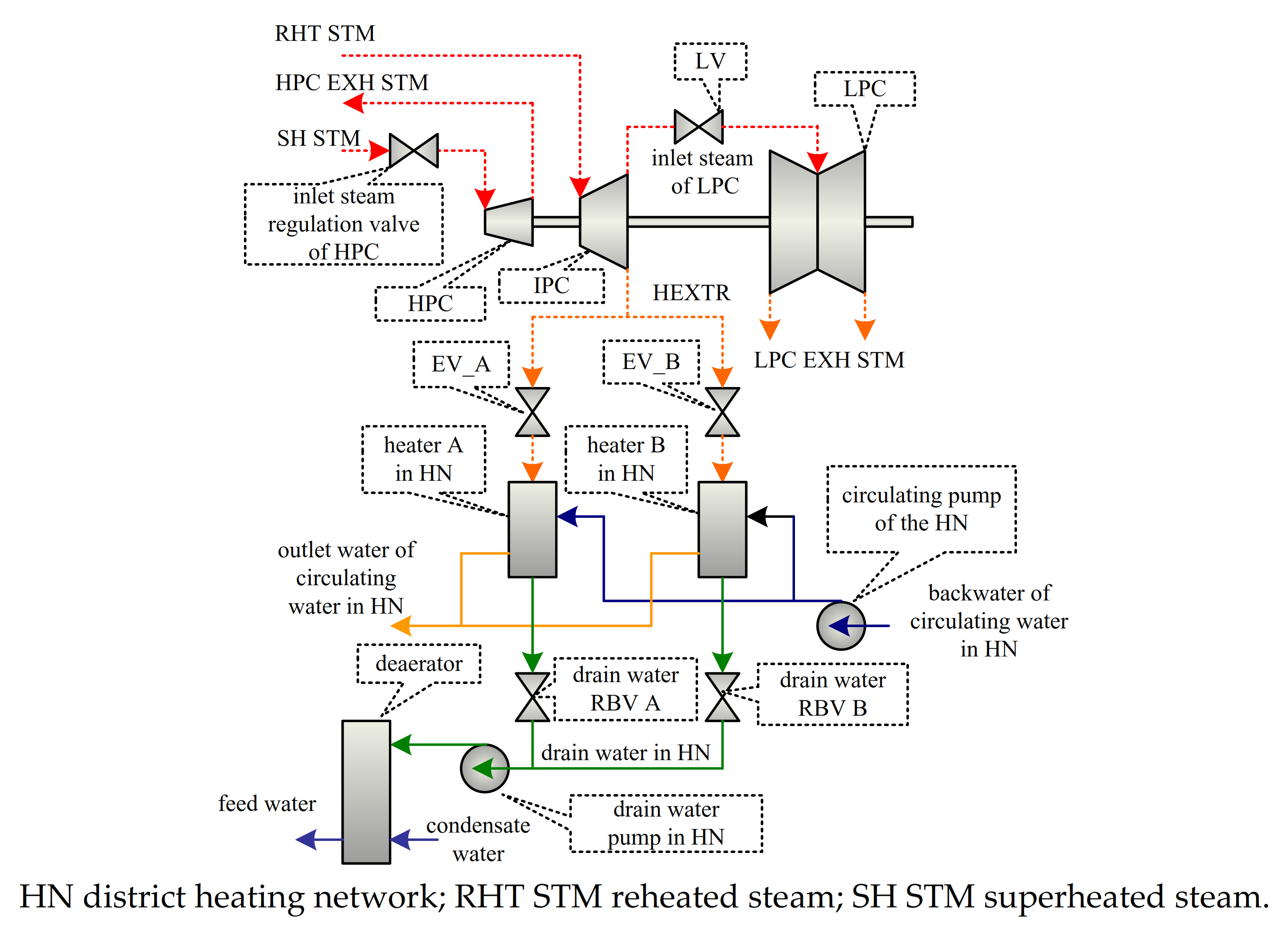
Most of the structure of the boiler and steam turbine in extraction CHP plant is the same as that of the condensing unit plant, and the main difference lies in the low-pressure side of the steam turbine. The thermal system structure of the heating part in the unit is shown in
Figure 1. The characteristics are summarized as follows. The two working stages of the LPC of the steam turbine are moved to the IPC to reduce the EXH STM temperature of the IPC for meeting the needs of heat supply. The HEXTR is drawn from the EXH STM of the IPC, and the pressure of the HEXTR is equal to the EXH STM pressure of the IPC. The LPC inlet steam regulation butterfly valve of low-pressure cylinder (LV) is installed in the connecting pipe of the IPC and LPC to adjust HEXTR pressure. The A and B sides of the HEXTR are fed into the heaters of the DHN by the HEXTR regulation butterfly valve (EV) and turned into the drain water of the DHN after releasing heat. The drain water in two sides converges after the drain water regulation valves A and B and is then fed into the deaerator by the drain water pump of the DHN. The EV on the A and B sides adjusts the flow rate of the HEXTR into the heaters on the A and B sides of the DHN, respectively. The A and B side drain water regulation valves control the water level of the A and B side heaters, respectively. The return water in the DHN goes through the circulating pump of the DHN to increase pressure and enters the A and B side heaters in DHN by absorbing heat to supply heating for users.
In terms of energy, heating load characterization should include three parameters: temperature, pressure, and flow rate of the HEXTR. An approximately proportional relationship exists between the temperature and pressure drops in the work process while steam flows in a turbine. The HEXTR pressure is adjusted by LV, and the HEXTR temperature is indirectly regulated by LV. The flow rate of HEXTR is mainly regulated by EV. The HEXTR pressure must be controlled within a certain range under heating conditions. Too high or low pressure will cause the EXH STM temperature of the IPC to exceed the design range of the steam turbine and lead to the abnormity of the axial thrust. When adjusting the HEXTR flow rate, the minimum inlet steam flow rate of the LPC must be guaranteed. The “blast” phenomenon will occur when steam working is insufficient in the LPC while the inlet steam flow rate is small, which endangers the safe operation of the last-stage blade of the LPC. Accurate monitoring of the HEXTR pressure and flow rate is needed to regulate the heat and electricity load and guarantee safe operation of the unit.
By analyzing the steam–water flow process of a heating unit, the following models may be used for soft sensing of the HEXTR flow rate.
(1) A mass–balance relationship exists among the HEXTR flow rate, the drain water flow rate of the heaters in the DHN, and the water level of the heaters in the DHN. However, the measurement error of the drain water flow rate in the DHN is large, and phenomena such as “flash evaporation” and “flash condensation” in the heater of the DHN cause the water level to fluctuate violently. The accuracy of the soft measurement is difficult to be guaranteed due to the operation of the equipment and the measuring device. Many CHP plants use a parallel operation mode to improve the reliability of heating, but this method is limited by the cross connection between the drain water of the heaters in two DHNs.
(2) A valve flow characteristic relationship exists among the HEXTR flow rate, the HEXTR pressure, the pressure of the heaters in the DHN, and the opening of the EV. This model has fast reaction speed but exhibits serious nonlinearity between the EV opening and the flow rate. Thus, an additional complex nonlinear correction must be carried out to improve its accuracy.
(3) The calculation of the overall heat balance characteristics of steam turbines shows that this method has high static accuracy in accordance with the national standard of China [
24]. However, the calculation method is complex, involves many auxiliary variables, and has the worst dynamic characteristics.
(4) The accuracy of the model can meet the requirement because of the use of the mass–balance relationship among the HEXTR flow rate, the last stage steam flow rate of the IPC, the inlet steam flow rate of the LPC, and the No. 5 extraction steam flow rate. Moreover, the quantity of the auxiliary variable and the amount of calculation are moderate, and the dynamic characteristic is better.
3. Basic Soft-Sensing Methods
3.1. Flügel Formula Method
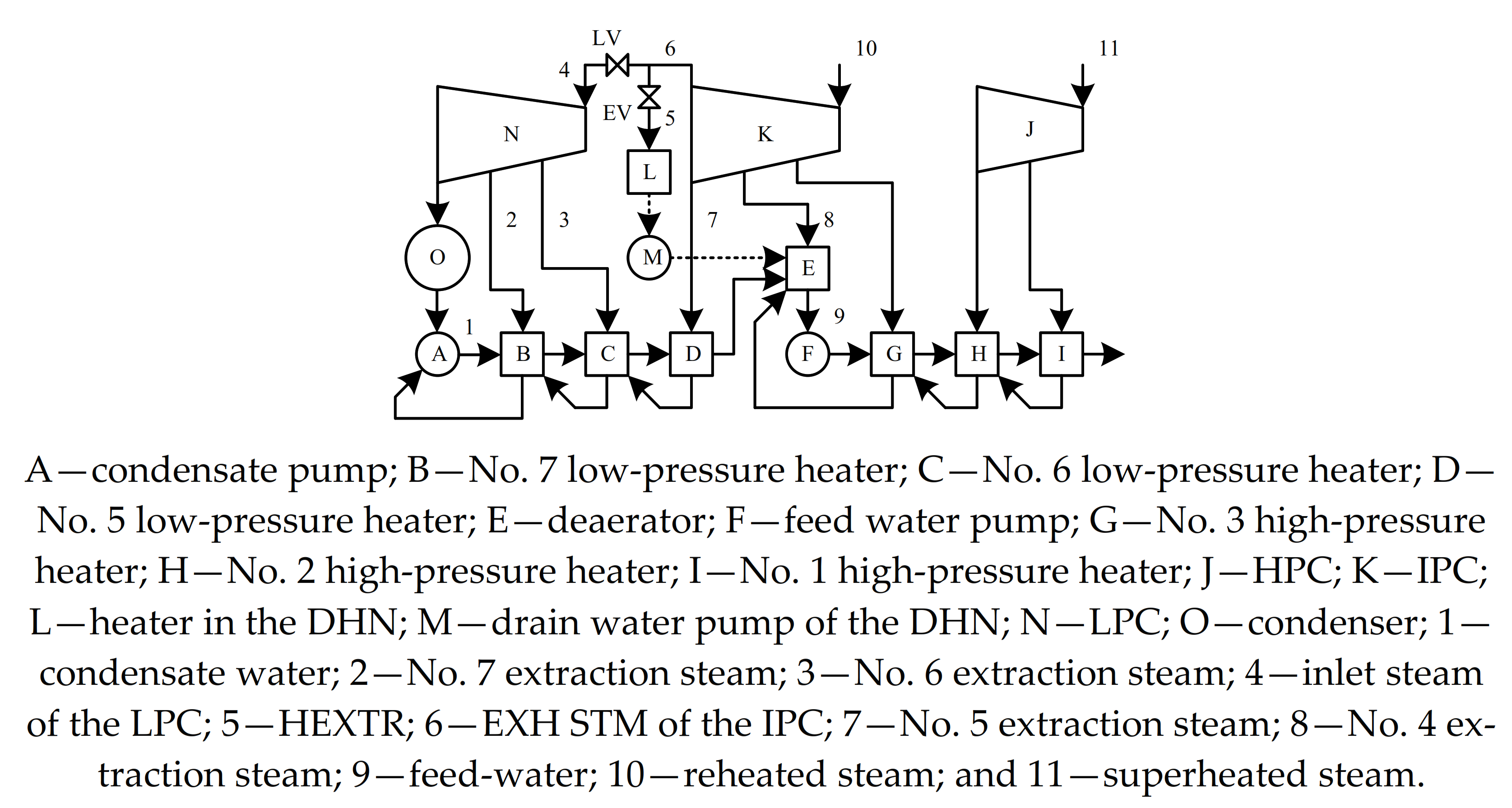
The typical steam–water flow process of the extraction heating unit is shown in
Figure 2. By ignoring the leakage of the shaft seal on the EXH STM side of the IPC, the mass–balance process on the side of the HEXTR can be described as
where
qesA is the HEXTR flow rate calculated by the Flügel formula, kg/s;
qms is the EXH STM flow rate of the IPC, kg/s;
q5s is the No. 5 extraction steam flow rate, kg/s; and
qls is the inlet steam flow rate of the LPC, kg/s.
According to the Flügel formula of the steam turbine [
25], Equations (2) and (3) can be listed as follows:
where
qms0 is the EXH STM flow rate of the IPC under rated heating conditions, kg/s;
p4s0 is the No. 4 extraction steam pressure under rated heating conditions, MPa;
pes0 is the pressure of the HEXTR under rated heating conditions, MPa;
T4s0 is the temperature of the No. 4 extraction steam under rated heating conditions, K;
p4s is the pressure of No. 4 extraction steam, MPa;
pes is the pressure of the HEXTR and is equal to the pressure of the No. 5 extraction steam, MPa; and
T4s is the temperature of the No. 4 extraction steam, K.
where
qls0 is the inlet steam flow rate of the LPC under rated heating conditions, kg/s;
pls0 is the inlet steam pressure of the LPC under rated heating conditions, MPa;
pxs0 is the EXH STM pressure of the LPC under rated heating conditions, MPa;
Tls0 the inlet steam temperature of LPC under rated heating conditions, K;
pls is the inlet steam pressure of LPC, MPa;
pxs is the EXH STM pressure of the LPC, MPa; and
Tls is the inlet steam temperature of the LPC, K.
Combining Equations (2)–(5) yields
The energy balance equation of the No. 5 low-pressure heater can be expressed as
where
E5 is the total enthalpy in the No. 5 low-pressure heater, kJ;
h5s is the specific enthalpy in the No. 5 extraction steam, kJ/kg;
q5w is the flow rate of the drain water of the No. 5 low-pressure heater, kg/s;
h5w is the specific enthalpy of the drain water in the No. 5 low-pressure heater, kJ/kg;
qcw is the flow rate of condensate water, kg/s;
h5cw is the specific enthalpy of condensate water on the outlet of the No. 5 low-pressure heater, kJ/kg; and
h6cw is the specific enthalpy of condensate water on the outlet of the No. 6 low-pressure heater, kJ/kg.
Under normal operation conditions, the low-pressure heaters should meet the following requirement. (1) Water level is under control. The volume of steam and the water in low-pressure heater are approximately unchanged. (2) The end difference of the low-pressure heater is approximately zero. (3) The specific enthalpy of condensate water on the outlet of low-pressure heater is equal to the specific enthalpy of drain water of low-pressure heater. The change in total enthalpy in the low-pressure heater mainly depends on the change in the specific enthalpy of saturated water and vapor.
Therefore,
where
V5 is the volume of the No. 5 low-pressure heater, m
3;
ρ5 is the average density of saturated water and saturated vapor in the No. 5 low-pressure heater, kg/m
3; and
h5 is the average specific enthalpy of saturated water and saturated vapor in the No. 5 low-pressure heater, kJ/kg.
Thus, by substituting Equations (9)–(11) into Equation (8), Equation (12) is obtained.
The density and specific enthalpy of saturated water and vapor can be determined by temperature. Moreover, the specific enthalpy of condensate water side can be approximately calculated by temperature. Linearizing Equation (12) yields
where
M5 is the fitting coefficient of thermal inertia of the No. 5 low-pressure heater, kJ/s·°C;
k3 is the coefficient for calculating specific enthalpy by the temperature of condensate water on the outlet of the Nos. 5 and 6 low-pressure heaters, kJ/kg·°C;
t5cw is the temperature of condensate water on the outlet of the No. 5 low-pressure heater, °C; and
t6cw is the temperature of condensate water on the outlet of the No. 6 low-pressure heater, °C.
Under static operation conditions, Equation (13) can be expressed as
By combining Equations (1), (6), (7), and (14) and using measurable parameters, the static value of the HEXTR flow rate can be calculated.
3.2. Thermal Balance Characteristics of Turbine Method
In accordance with the thermal balance characteristics of the regenerative heat system of a turbine and
Figure 1, the mass and the energy balance equations of every heater under static operation conditions can be expressed as follows:
For the No. 1 and No. 5 (
i = 1, 5) heaters, the equations are
For the Nos. 2, 3, 6, and 7 heaters (i = 2, 3, 6, 7), the equations are
For the No. 4 deaerator (i = 4), the equations can be expressed as follows:
For the heater of the DHN, the equation can be expressed as
In Equations (15)–(21), qis is the extraction steam flow rate into each heater, kg/s; qiw is the drain water flow rate out of each heater, kg/s; his is the specific enthalpy of the extraction steam into each heater, kJ/kg; hiw is the specific enthalpy of the extraction steam drain water out of each heater, kJ/kg; qicw is the condensate or feed water flow rate of pipe side into each heater, kg/s; hicw is the specific enthalpy of the condensate or feed water of pipe side out of each heater, kJ/kg; qfw is the feed water flow rate, kg/s; qesB is the HEXTR flow rate using heat balance calculation, kg/s; qhw is the drain water flow rate of the heaters in the DHN, kg/s; and hhw is the specific enthalpy of the drain water of the heaters in the DHN, kJ/kg.
All high- and low-pressure heaters adopt the working mode of successive drain water artesian flow, which can be expressed as
Under pure condensation condition, knowing the condensate flow, the specific enthalpy of each section of the extraction steam is calculated according to the thermodynamic properties of water and steam. Then, extraction steam flow in each section and feed water flow can be calculated by Equations (15)–(23). However, under heating condition, there is an unknown variable qhw in Equations (15)–(23). Thus, these equations have no direct solution. In order to solve the equations, iterative calculation must be used. Since all thermal power units install feed water flow rate measuring device. The equations can be solved by considering qfw as a known variable and substituting qfw into the equations. Thus, the accuracy of HEXTR flow rate under static conditions mainly depends on the measurement accuracy of the condensate and feed water flow rates. The measurement accuracy of feed water flow rate is generally considered to be lower than that of the condensate water flow rate. Under pure condensing condition, the typical operation point can be selected, and the measured value of the feed water flow rate can be corrected using the results of the heat balance calculation of the turbine. The corrected feed water flow rate has the same accuracy as the condensate water flow rate. A high static accuracy can be obtained when the former is applied to the calculation of HEXTR flow rate.
Theoretically, the coefficients in the Flügel formula can also be calculated directly from the parameters of the steam at a static operation point. In reality, the measuring points of pressure and temperature of every stage extraction steam are installed on the extraction steam pipes outside the turbine, which differ from the pressure and temperature of the inner work stage of the turbine. Thus, application of the Flügel formula will result in a large error. The heat balance calculation of the turbine is based on the working medium energy balance process of the heater, and no such error is encountered.
3.3. Butterfly Valve Flow Characteristics Method
The valve flow characteristic curve describes the functional relationship between the valve opening and the flow rate under the condition of fixed front and rear differential pressure of the valve. The consistency of the flow characteristic curve of the large caliber RBV outperforms those of the other types of regulating valves. For the HEXTR RBVs, the flow characteristics are approximately given as follows:
where
qes0 is the HEXTR flow rate under the standard condition, Kg/s;
KD is valve coefficient, Kg/s; and
ues is the butterfly valve opening of HEXTR, %.
After adding the correction of the differential pressure between the front and rear of the valve, the relationship among the flow rate of the HEXTR, the opening of the valve, and the differential pressure between the front and rear of the valve is expressed as follows:
where
qesC is the HEXTR flow rate calculated by the butterfly valve characteristics, kg/s;
pes0 is the HEXTR pressure under standard condition, MPa; and
pls0 is inlet steam pressure of the LPC under rated heating conditions, MPa.
Calculation of the HEXTR flow rate using the flow characteristics of the RBV is performed through Equation (27).
The units are generally installed with two sets of the HEXTR RBVs and DHN heaters, which are simultaneously operating under normal conditions, and the opening of the two butterfly valves is the same. Every HEXTR flow rate can be calculated separately, and the total HEXTR flow rate can be summed up.
4. Frequency Complementary Information Fusion
The Flügel formula, turbine heat balance, and butterfly valve flow characteristic methods have different application conditions and characteristics.
In the Flügel formula method, the thermal inertia of the No. 5 low-pressure heater is neglected in the calculation of the No. 5 extraction steam flow rate. Moreover, the thermal inertia time of the No. 5 low-pressure heater in the large capacity unit is nearly 30–60 s. To maintain the dynamic consistency, the EXH STM flow rate of the IPC and the inlet steam flow rate of the LPC also need to be filtered on the same time scale. Thus, this method is only suitable for static or slowly varying conditions. The calculation process is relatively simple and can be realized by configuration. In addition, three unknown coefficients in the equations, k1, k2, and k3, must be calibrated.
The heat balance method of the turbine is only suitable for the condition under which the parameters of the turbine are in absolute steady state [
24]. Furthermore, the calculation process is complex, which is difficult to be realized by configuration. However, it has the highest static accuracy.
The method of butterfly valve characteristics can reflect the change in the HEXTR flow rate in real time when the opening of the butterfly valve and the pressure of the HEXTR change. This method has fastest dynamic response speed and low static accuracy.
The process of soft sensor fusion algorithm is described below.
(1) Several typical operation points are selected to record the parameters of flow rate, temperature, and pressure for the calculation of the turbine heat balance under steady state conditions. Then, according to Equations (15)–(23), the HEXTR flow rate at each operation point is calculated.
(2) The parameters of each operation point and the calculated HEXTR flow rate are substituted into Equations (1), (6), (7) and (14). The equations of the Flügel formula method for each operation point are obtained. Then, the least square solutions of k1, k2, and k3 can be determined by inverse calculation.
(3) The parameters of each operation point and the calculated HEXTR flow rate are substituted into Equation (27). Then, the average value of k4 of different operation points can be obtained.
(4) The Flügel formula calculation logic for the HEXTR flow rate based on Equations (1), (6), (7) and (14) is constructed.
(5) The flow characteristic method of the butterfly valve for the calculation logic of the HEXTR flow rate based on Equation (27) is constructed.
(6) The results of the two methods are fused. The low-frequency components of the Flügel formula method and the high-frequency components of the butterfly valve characteristic method are fused as soft-sensing outputs.
A frequency complementary information fusion method for the soft sensor of boiler heat signal is proposed in Ref. [
14]. This method is applied to the soft sensor of the RHT STM flow rate signal in Ref. [
26]. In addition, Ref. [
27] improves this method and proposes a signal decomposition method. According to the concept in Ref. [
27], the HEXTR flow rate signal is decomposed as
where
qes(
s) is the HEXTR flow rate signal, kg/s, and
G(
s) is the transfer function of the low-pass filter.
Then, the signal
qes(
s) is divided into two parts: the high-frequency component
qesH(
s) and the low-frequency component
qesL(
s). The decomposition process is reversely calculated, and the signal fusion can be realized subsequently, as shown in Equation (31).


