Article

Dynamic Stability and Flight Control of Biomimetic Flapping-Wing Micro Air Vehicle

Department of Aerospace Engineering, Korea Advanced Institute of Science and Technology, Daejeon 34141, Korea
*
Author to whom correspondence should be addressed.
Aerospace 2021, 8(12), 362; https://doi.org/10.3390/aerospace8120362
Submission received: 18 October 2021 / Revised: 18 November 2021 / Accepted: 20 November 2021 / Published: 24 November 2021
(This article belongs to the Special Issue Bioinspired Flying Systems)

Abstract

:
This paper proposes an approach to analyze the dynamic stability and develop trajectory-tracking controllers for flapping-wing micro air vehicle (FWMAV). A multibody dynamics simulation framework coupled with a modified quasi-steady aerodynamic model was implemented for stability analysis, which was appended with flight control block for accomplishing various flight objectives. A gradient-based trim search algorithm was employed to obtain the trim conditions by solving the fully coupled nonlinear equations of motion at various flight speeds. Eigenmode analysis showed instability that grew with the flight speed in longitudinal dynamics. Using the trim conditions, we linearized dynamic equations of FWMAV to obtain the optimal gain matrices for various flight speeds using the linear-quadratic regulator (LQR) technique. The gain matrices from each of the linearized equations were used for gain scheduling with respect to forward flight speed. The reference tracking augmented LQR control was implemented to achieve transition flight tracking that involves hovering, acceleration, and deceleration phases. The control parameters were updated once in a wingbeat cycle and were changed smoothly to avoid any discontinuities during simulations. Moreover, trajectories tracking control was achieved successfully using a dual loop control approach. Control simulations showed that the proposed controllers worked effectively for this fairly nonlinear multibody system.

1. Introduction

In recent years, research and development involving bio-inspired aerospace systems have increased because of surging demands in micro and nano air vehicles for both commercial and military applications with stringent size, nimbleness, concealment, and space requirements. Moreover, these systems are also expected to possess high agility, hovering capability, sudden obstruction avoidance, quick shifting from hovering to forward speed and vice versa, and moving object tracking with smart navigation. These exceptional features are common traits of nature-based flyers; therefore, scientists are trying to mimic their remarkable flights. For this, a large amount of work has been done in the design and development of micro-scale flying robots such as KUBeetle-S [1], autonomous FWMAV [2], saturn aircraft [3], robobee [4], robotic dragonfly [5], ornithopter-type MAV [6], locust-like small-scale robots [7], and entomopter [8]. Mimicking insects’ flight impose challenges in several fields that still need detailed attention, including low Reynolds number-based unsteady aerodynamics, mathematical modeling, flight dynamics, trim methodologies, control approaches, miniature hardware requirements, lightweight materials, and power system requirements.
Most of the FWMAV’s flight dynamics and control work in literature is based on limitations and assumptions considering varying degree of complexity in various areas. These questionable aspects include consideration of wing inertia [9], flexibility of wing [10], nonlinearity of mathematical model [11,12], fidelity of the aerodynamic model [13,14], and consideration of the coupling between the planes of motion [15]. Different types of research works are available that have ignored or adopted one or more of these aspects for the FWMAV’s stability analysis and control implementation. This may result in less accurate characterization of the system’s dynamic stability, and implementing control to it might lead to incorrect results in flight performance analysis.
Three assumptions are chiefly employed while deriving the nonlinear equations of motion: neglecting the wings inertial effects, averaging the FWMAV’s body dynamics over each flapping cycle, and linearizing the nonlinear time-periodic (NLTP) model for ease in stability characterization and control implementation [15,16]. Using these assumptions, the eigenvalue analysis technique is used for stability characterization. Most of the earliest studies have ignored the wings inertial effects on the complete FWMAV’s system for either stability and/or control work [11,17,18,19,20,21,22,23,24,25]. Taylor and Thomas [11,17] were the first to analyze the dynamic flight stability of flapping wings flight but also ignored the wing inertial effects like other studies [18,19,20,21,22,23,24,25]. However, Orlowski and Girard [9] in their simulations compared the results with and without the wing inertia. The simulations comparison showed that neglecting the wing inertia caused a significant difference in the results. Similarly, some researchers reported that considering the wing inertia is necessary to accurately understand and simulate the FWMAV system [26,27,28,29,30].
Another simplifying assumption is that most of the stability analysis studies for hovering and/or forward flight are conducted on the basis of averaging of the body dynamics over each flapping cycles [11,17,18,19,21,22,25]. Averaging theorem is based on the singular perturbation theory, and smaller errors are expected for higher flapping frequencies as suggested by Taha et al. [16]. Moreover, the third assumption of linearizing the NLTP model to linear time invariant (LTI) model for undergoing the stability analysis of FWMAVs is also widely adopted [11,19,31]. Dietl and Garcia [20] utilized floquet theory for analyzing the dynamic stability using a linearized time-periodic (LTP) model, which is also supported by other researchers [16,32,33]. In contrast, some studies have used direct time integration approach to solve the fully coupled nonlinear FWMAV model for stability analysis, which incorporates NLTP effects [12,15,34].
Regarding aerodynamics, many studies are available that used either high-fidelity or low-fidelity models with their own advantages and disadvantages. High-fidelity models include computational fluid dynamics (CFD), which are related to the direct numerical simulations (DNS), such as employed by Sun and Xiong [25], Sun et al. [19], Gao et al. [35], and Xiong and Sun [31]. Although these high-fidelity models much better incorporate the unsteady flow effects, they are computationally very expensive and may not be the optimal choice for intensive stability analysis and control simulations, as discussed by Taha et al. [16]. On the other hand, low-fidelity aerodynamic models, such as steady and quasi-steady (QS) models, consume less computational cost and time and produce reasonable results for both stability and control analyses. The steady state models are based on different aerodynamic theories: actuator disk theory as utilized by Pennycuick [36] and Ellington [37], lift line theory devised by Prandtl and employed by Phlips et al. [38], and vortex ring theory as suggested by Ansari [39]. In contrast, basic QS aerodynamic models suggest that the instantaneous forces on the wings are fully dependent on the instantaneous flapping velocity, rotational angle, and wing’s design, regardless of the flow field. Xuan et al. [40] reviewed these aerodynamic models and categorized them as Osborne, Walker, and Dickinson models, which are based on blade element theory that ignores span wise flows and wake-related unsteady effects. However, the modified QS model in the current study considered the additional lift from leading edge vortex (LEV) and the effects of wing rotation as discussed in previous studies [41,42].
Dynamic stability has been extensively studied because most insect-like FWMAVs do not have tail wing for stabilization. Taha et al. [43] conducted a longitudinal stability analysis of the averaged and linearized dynamics of hovering insects. They found that the mean angle of attack and flapping frequency have effects on damping in longitudinal plane. Sun et al. [19] also analyzed the hovering flight regarding longitudinal flight dynamics characteristics of four different insects. They found that all of the four insects have one unstable oscillatory mode, one stable fast subsidence mode, and one stable slow subsidence mode. Au and Park [44] showed that modes of FWMAV can be changed depending upon the location of the center of gravity position. Regarding forward flight, some studies were also conducted for different insect models [10,31,45]. These studies showed that in longitudinal plane, all of the insect models are unstable. Moreover, Cheng and Deng [46] explained the principles of the flapping counter torque (FCT), which results in significant damping in system dynamics.
In order to control FWMAV, which is a nonlinear system, both linear and nonlinear control methods have been applied. For linear control methods, Oppenheimer et al. [47] used wing bias as the control input. The difference in flapping frequency between upstroke and downstroke was generated by the wing bias. A linear controller was designed to track the trajectory in three-dimensional space. Moreover, Loh et al. [48] used the proportional–integral–differential (PID) controller for the hovering FWMAV. Flapping frequency, phase difference of wing kinematics, and shift in center of gravity were used as the control inputs. For nonlinear control method, Khanmirza et al. [49] designed a controller with quaternion-based dynamic wrench method for trajectory tracking. With that controller, the FWMAV achieved the cruise and the Cuban-8 maneuvers. Banazadeh and Taymourtash [50] applied an adaptive sliding mode technique for position control in the presence of uncertainties. Three control inputs were used: flapping amplitude, stroke plane angle, and phase of flapping motion. Desired trajectory can be followed without prior information about uncertainties. Although the above research works have provided essential information for FWMAV control, these studies have ignored the wing inertia effects in their control simulations. A few researchers have considered the wing inertial effects in their control simulations [14,51,52].
A few previous studies have dealt with multibody model incorporating the wing inertia effect and FWMAV dynamics–aerodynamics coupling. Since the multibody model of a novel flapping wing rotor (FWR), which included the wing inertia, agreed well with experimental results [53], the current study also incorporated the wing inertia effect. The current study employed a multibody dynamics simulation framework that was appended with a gradient-based trim search algorithm to find the trimmed wing kinematics and initial conditions for velocities to obtain a linear periodic-based solution for the nonlinear FWMAV model, which has been ignored in previous studies [19,25,31]. These previous studies neglected the influence of FWMAV’s body dynamics and dynamics–aerodynamics coupling and did not provide the periodic solution in free-flying conditions as asserted by Kim et al. [45] and Wu et al. [54]. Additionally, the current study utilized a modified quasi-steady (QS) aerodynamics model that considers the wing pitching moment effect, added-mass effect, and rotational flow effect and accounted for the shift in the aerodynamic center at higher angles of attack. Using the simulation framework, we characterized longitudinal dynamic stability for simplified wing kinematics, as it is suitable for control implementation purposes. Regarding FWMAV control, previous studies have considered controlling only the hovering or low forward speeds conditions [48,55], while some studies have ignored wings inertial effect in controlling the FWMAV [48,49,50,55,56,57,58]. However, the current study considered controlling the hovering condition, forward flight conditions, transition flight conditions, and trajectories tracking while considering the wings inertial effects. Since dynamic characteristics, trim conditions, and aerodynamics characteristics vary with the flight speed of the FWMAV, the controllers designed by linearizing the system around hovering state cannot function well when the FWMAV is required to accelerate. Consequently, a transition flight controller was designed that utilizes speed-dependent gain scheduling to account for our parametric varying nonlinear system. Using the trim search results, we linearized the equations of motion at various flight speeds to obtain the optimal gain matrices using the LQR control technique. These gain matrices were utilized to model the gain function that varies with the forward speed references. This speed-dependent gain matrix function is input to the feedback control loop of the FWMAV in control simulations such as transition flight tracking that involves hovering, acceleration, constant speed, deceleration, and hovering phases. Results show the controller worked well with varying forward flight speed references. Moreover, previous studies have used complicated nonlinear control methods for position controlling [14,51,52]; however, in the current study, by adjusting forward speed references with a proportional-integral (PI) controller that uses position errors as input, we tracked various reference trajectories with increasing level of complexity to validate the effectiveness of our position controller. Control simulations showed that combinations of different linear control techniques work well to effectively control both the linear and nonlinear models.
The rest of the paper is organized as follows: In Section 2, the materials and methods are presented, including FWMAV model and coordinate systems definitions, details of the wing kinematics and aerodynamic model, the multibody dynamics simulation framework, and the gradient-based trim search algorithm. It also details the linearization of nonlinear equations of motion for the FWMAV system. Moreover, it explains the design of the controller for transition flight tracking by obtaining optimal gains with the augmented LQR control technique and the design of trajectory tracking controller. Results and discussion are presented in Section 3. Firstly, it shows the results of stability characterization for longitudinal dynamics in both hovering and forward flight. Next, the results of fixed flight conditions’ control and transition flight control are discussed. Furthermore, Section 3 details the results of various reference trajectories tracking. Finally, concluding remarks are presented in Section 4.

2. Materials and Methods

2.1. FWMAV Multibody Model and Coordinate Systems

2.1.1. FWMAV Multibody Modeling

In this study, a full-scale multibody dynamic model of a hawkmoth-like FWMAV is considered. The reference insect is modeled into five rigid parts: head, thorax, and abdomen that form the main body and a pair of wings to precisely locate the center of gravity as shown in Figure 1 [10,15,35,45,59]. Since the fore and hind wings flap in a synchronous manner, they are assembled as a single wing. Each wing is connected to the thorax with a 3 degrees of freedom (DOF) revolute joint, while the head, thorax, and abdomen are connected with fixed joints. The morphological parameters for the reference hawkmoth-like FWMAV are obtained from Gao et al. [35], Ellington [59], Hedrick and Daniel [60], and O’Hara and Palazotto [61]. Each wing is divided into five strips of width Δ r for applying the QS aerodynamic model as depicted in Figure 1. Figure 1 and Table 1 detail the morphological data and nomenclature related to the reference FWMAV model utilized in this study.

2.1.2. Coordinate Systems

To model the 6-DOF FWMAV system, we used six different coordinate systems, as shown in Figure 1. Global coordinate system [xG yG zG] is used for defining the global locations, attitudes, and linear and angular velocities of the system. This frame is utilized in obtaining equilibrium conditions of the model at different flight speeds. It is also used for reference trajectories tracking. Body coordinate system [xb yb zb] is connected to the location of the overall center of mass of the system. All body flight states are defined in this coordinate system. When all Euler angles for FWMAV attitudes are zero, the xb axis of this frame is parallel to the xG axis. The yb axis stretches out to the right wing’s tip. The body pitch angle χ is defined as the angle between the xG axis and the body longitudinal axis. The positioning of the body coordinate system with respect to the global coordinate system is parameterized by this sequence of Euler angles: Ψ (yaw), Θ (pitch), and Φ (roll). Stroke-plane coordinate system [xsp ysp zsp] is the key frame to describe the resultant aerodynamic forces and moments. The induced aerodynamics forces and moments by the 6-DOF body’s motion are added to the instantaneous ones as produced by each aerodynamic strip in this frame. The angle β between the xsp axis and the xG axis is defined as the stroke-plane angle. Wing-fixed coordinate system [xw yw zw] is defined at the wing-base pivot point. The yw axis of this coordinate system is stretched out in the span-wise direction and defines the wing pitching axis. The wing-fixed coordinate system defines the wing kinematics on the basis of the stroke-plane coordinate system. Aerodynamic strip coordinate system [xstr ystr zstr] is connected to each of the aerodynamic strips of both of the wings. The purpose of this coordinate system is to describe the periodic aerodynamic forces and moments on each of the strip along the wingspan by applying the blade-element theory on the basis of the experimentally obtained aerodynamic coefficients. Lastly, the trim coordinate system [xtrim ytrim ztrim] is defined when the trim conditions are searched during the implementation of the trim search algorithm. The xtrim axis of this coordinate system is parallel to the global coordinate system’s xG axis during trimmed state. This coordinate system is attached to the center of mass of the FWMAV model.

2.2. Wing Kinematics and Aerodynamic Model

2.2.1. FWMAV Wing Kinematics

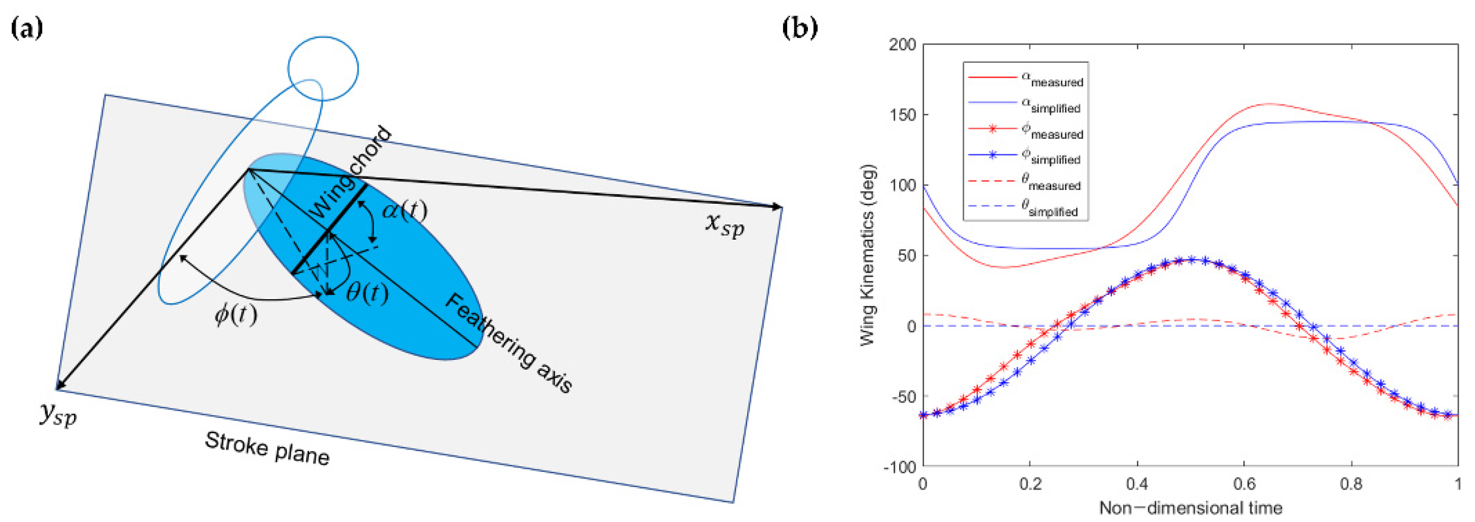
For the stability and control analyses of the FWMAV, we employed a simplified wing kinematics in the current study, and its comparison with measured hawkmoth wing kinematics is shown in Figure 2. The measured hawkmoth wing kinematics was extracted from Willmott and Ellington [62]. The wing kinematics for FWMAV is modeled by a 3-DOF revolute joint with three rotational angles at the wing-base pivot point. It is classified as stroke positional angle ϕ(t), feathering or rotational angle α(t), and deviation angle θ(t). Berman and Wang [63] detailed the simplified motion as shown in Equation (1). Here, the coefficient Cα is the tuning coefficient for the feathering angle α(t), and it also alters the stroke reversal time of the feathering angle. The simplified wing kinematics used in this study is shown below:
ϕ ( t ) = ϕ 0 ϕ a m p sin ( 2 π f t + π / 2 ) α ( t ) = α 0 α a m p tanh ( C α ) tanh ( C α sin ( 2 π f t ) ) θ ( t ) = 0
where f = flapping frequency, ϕamp = 55 deg, ϕ0 = mean stroke positional angle, αamp = 45 deg, α0 = mean feathering or rotational angle, and Cα = 2.6, for the current work. This baseline wing kinematics and flapping frequency are used as starting point to search the trim conditions at each flight speed. The control simulations show that flapping frequency, mean stroke positional angle, and mean rotational angle give full control authority in longitudinal plane.

2.2.2. Quasi-Steady Aerodynamic Model

A modified semi empirical quasi-steady (QS) aerodynamic model was used in the current study. The QS model was developed and experimentally validated by Han et al. [42]. This model also considers the effect of wing pitching moment due to changing aerodynamic center at higher angles of attack which was mostly neglected in previous studies [24,46,63,64]. For the application of the blade element theory, Kim et al. [45] divided each wing into five aerodynamic strips, and their longitudinal eigenvalues agreed well with the result of Cheng and Deng [46]. Therefore, the present study also divided each wing into five strips as a compromise between accuracy and computational time. The QS aerodynamic model ignores the effect of the flight speed on aerodynamic coefficients. The net aerodynamic forces and moments for one single wing are integrated along the wingspan and can be represented as follows:
L = L t r a n s l a t i o n a l + L r o t a t i o n a l + L a d d e d m a s s = 0 R w C L ρ 2 V n 2 c d r + 0 R w C R ρ α ˙ n V n c 2 d r · cos α +   0 R w π 4 ρ c 2 ( ϕ ¨ r ) sin α d r · cos α
D = D t r a n s l a t i o n a l + D r o t a t i o n a l + D a d d e d m a s s = 0 R w C D ρ 2 V n 2 c d r + 0 R w C R ρ α ˙ n V n c 2 d r · sin α + 0 R w   π 4 ρ c 2 ( ϕ ¨ r ) sin α d r · sin α
M = M t r a n s l a t i o n a l + M r o t a t i o n a l + M a d d e d m a s s = 0 R w C M ρ 2 V n 2 c 2 d r + 0 R w C R ρ α ˙ n V n c 2 d r · ε + 0 R w π 4 ρ c 2 ( ϕ ¨ r ) sin α d r · ε
Here, all calculations are performed for each strip and then integrated over the wingspan for obtaining the overall instantaneous aerodynamics caused by the flapping motion of the wings. The net lift L, drag D, and moment M can be computed by above equations that are dependent upon the wing kinematics as presented earlier. The lift force is along the zsp axis, drag force is along the xsp axis, and the wing pitching moment is about the ysp axis. Here, the coefficients of lift, drag, and moment are represented by CL, CD, and CM, respectively. The rotational force coefficient is represented by CR, the incident airflow velocity on each strip of the wing is represented by V n , the net effective angle of attack of each strip is shown as α n , the air density is represented by ρ, the span-wise position of each strip is shown as r, the chord length of each strip is indicated by c, the width of each strip is shown by dr, and the distance from the yw axis to the half chord line is represented by ε , which is used as the moment arm for moments calculations due to added-mass effect and rotational force effect. The V n is defined by Equation (5).
V n =   [ ( y w _ n   ϕ ˙ ( t ) + u s p cos ( | ϕ ( t ) | ) + v s p sin ( ϕ ( t ) ) + y w _ n   r s p ) 2 + ( y w _ n   θ ˙ ( t ) + w s p + y w _ n   p s p cos ( ϕ ( t ) ) + y w _ n   q s p sin ( | ϕ ( t ) | ) 2 ] 1 / 2
where yw_n represents the location of each strip along the yw axis in the wing-fixed coordinate system. All of the linear and angular velocity components are transformed to the stroke-plane coordinate system from the body coordinate system and represented by the subscript sp such as usp and rsp.
The modified QS aerodynamic model describing the aerodynamic coefficients for the instantaneous forces and moments is based on the research of Han et al. [42] and is adopted from Kim et al. [45] using experiments involving scaled-up hawkmoth wing in a mineral oil tank (TOTAL Diel MS 7000). This model is represented by Equations (6)–(9).
C L ( α n ) = 1.511 sin ( 0.01297 α n + 2.59 ) + 1.724 sin ( 0.03448 α n 0.5014 )
C D ( α n ) = 70.71 sin ( 0.03175 α n + 0.1737 ) + 69.4 sin ( 0.03229 α n + 3.319 )
C M ( α n ) = 12.77 sin ( 0.02357 α n + 3.212 ) + 12.26 sin ( 0.02473 α n + 0.07334 )
C R , t h e o r e t i c a l = π ( 0.75 x ^ 0 )
where n represents the aerodynamic strip number, and x ^ 0 = x / c , where x is the distance between the leading edge and the wing pitching axis yw. Note that since the effective angle of attack and the incident airflow are dependent upon the wing kinematics and induced velocity caused by the horizontal and vertical inflow components of all of the 6-DOF body states, they are also incorporated in the modified QS aerodynamic model. This ensures the accurate simulation of the flight dynamics by associating the time varying 6-DOF body flight states to the aerodynamic model. The effective angle of attack of each strip α n is the sum of the geometric angle of attack α ( t ) defined by the rotational angle of wing kinematics and the angle of attack caused by the vertical and horizontal inflow components in the stroke-plane coordinate system, as shown below. For more details about aerodynamic model, refer to Kim et al. [45].
α n = α ( t ) + tan 1 ( y w _ n   θ ˙ ( t ) + w s p + y w _ n   p s p cos ( ϕ ( t ) ) + y w _ n   q s p sin ( | ϕ ( t ) | ) y w _ n   ϕ ˙ ( t ) + u s p cos ( | ϕ ( t ) | ) + v s p sin ( ϕ ( t ) ) + y w _ n   r s p )

2.3. Multibody Dynamics Simulation Framework and Trim Search Algorithm

2.3.1. FWMAV Multibody Dynamics Simulation Framework

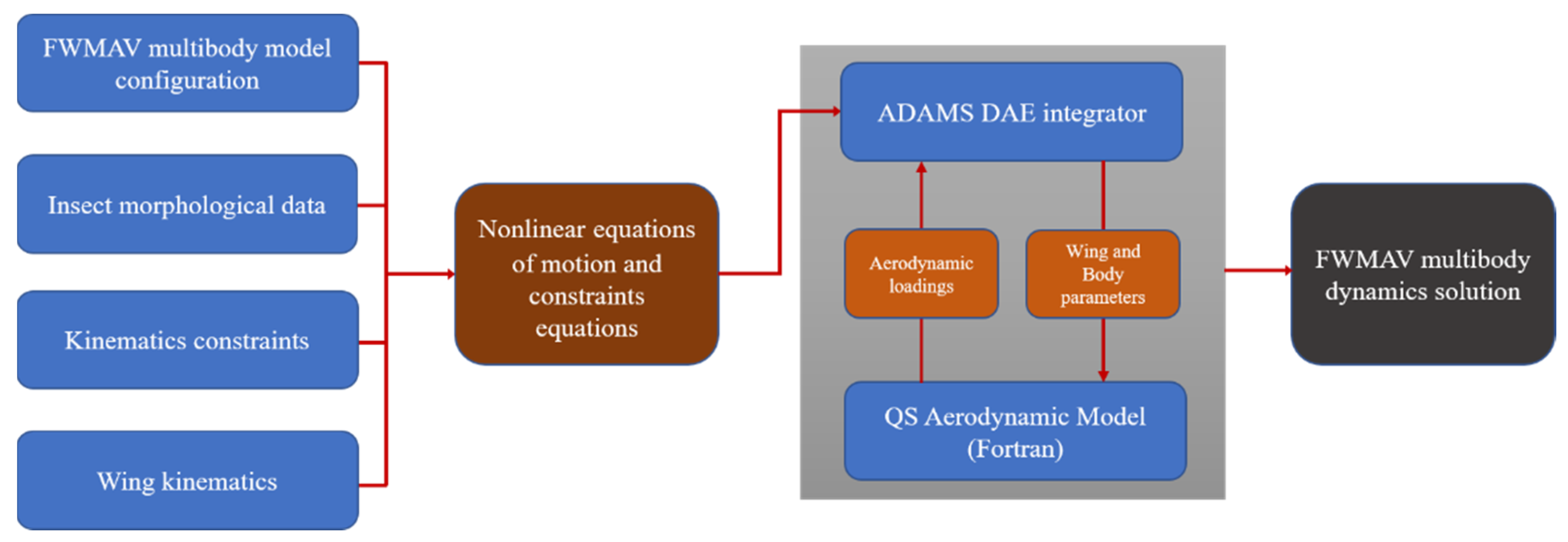
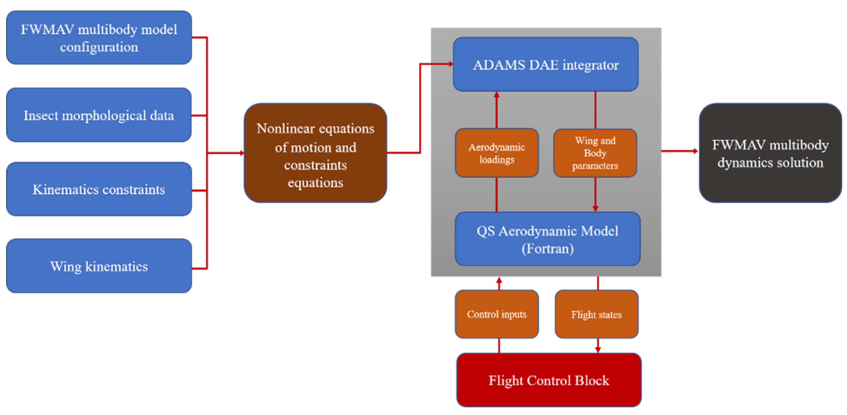
A multibody dynamics simulation framework for the reference insect model was employed in the current study for solving the nonlinear equations of motion, and it is based on various flapping flight studies by Pfeiffer et al. [65], Kim and Han [15], and Lee et al. [66]. The multibody dynamics code (MSC.ADAMS), is used for the development of this simulation framework, and the QS aerodynamic model (written in FORTRAN) is integrated into it, as shown in Figure 3. Here, ADAMS solver requires the FWMAV model, morphological data, kinematics constraints, and wing kinematics along with the aerodynamic loadings. The forces and moments for the nonlinear model are evaluated on the basis of the aerodynamic loadings from the QS aerodynamic model that requires the wing and body parameters. For the multibody modeling, the model is composed of five rigid bodies and four kinematics constraints. Two kinematics constraints join the three bodies (head, thorax, and abdomen) with fixed joints, and two other kinematics constraints link the two wings to the thorax with 3 degrees of freedom revolute joints. In ADAMS, the nonlinear equations of motion for system are expressed in the form of differential-algebraic equations (DAE formulation) as shown in Equation (11), which are dependent upon the multibody model configuration and the constraints applied.
M s q ¨ + η q T λ P T G ( q , q ˙ ) = 0 η ( q , t ) = 0
where Ms represents the mass matrix of the dynamic system, q is the set of coordinates depicting the displacements, η is the set of the model configuration and applied kinematics constraints equations, λ represents the Lagrange multipliers for handling multiple constraints, G denotes the set of applied forces and gyroscopic terms of the inertial forces, PT represents the matrix that projects the applied forces in the q direction, and ηq represents the gradient of the constraints at any given state.
This simulation framework uses the GSTIFF integrator developed by Gear [67] to solve the nonlinear DAE model. The solution process for this integrator occurs in two phases, namely, the prediction phase and the correction phase. The integrator employs Taylor’s series for the prediction phase, which is an explicit process. In contrast, the correction phase (implicit process) occurs after the prediction phase, and it is based on the iterative Newton–Raphson algorithm. For the convergence of the DAE integrator and other details, refer to [15,45,65,66,67].

2.3.2. Gradient-Based Trim Search Algorithm

During the trimmed flight, all 6-DOF forces and moments are in equilibrium and do not require extra control efforts to maintain that state unless there are some perturbations. Trim flight conditions are evaluated for both hovering and forward flight conditions. Trim conditions are difficult to find for FWMAV model as it involves periodic changes in the aerodynamic forces and moments. In this study, a gradient-based trim search algorithm was utilized that is based on the studies of Lee et al. [66] and Kim et al. [45]. This algorithm finds the wing kinematics and initial conditions as shown in Equation (13) that satisfies the trim criteria mentioned in Equation (12). The overbar denotes the wingbeat cycle averaged values that can be evaluated by Equation (14).
F ¯ = [ F ¯ x     F ¯ y     F ¯ z ] = [ 0       0       m s g ] M ¯ = [ M ¯ x   M ¯ y   M ¯ z ] = [ 0       0       0 ] x ¯ = [ u ¯   w ¯   q ¯   Θ ¯   v ¯   p ¯   r ¯   Φ ¯ ] = [ u o     0     0     0     0     0     0     0 ]
[ f o ,     α o ( t ) ,     ϕ o ( t ) ,     θ o ( t ) ] | F ¯ = M ¯ = 0
F ¯ = 1 T a T b T F ( t )   d t T = 1 / f ,     t [ a T , b T ] ,     a < b ,     f o r   a l l   a , b
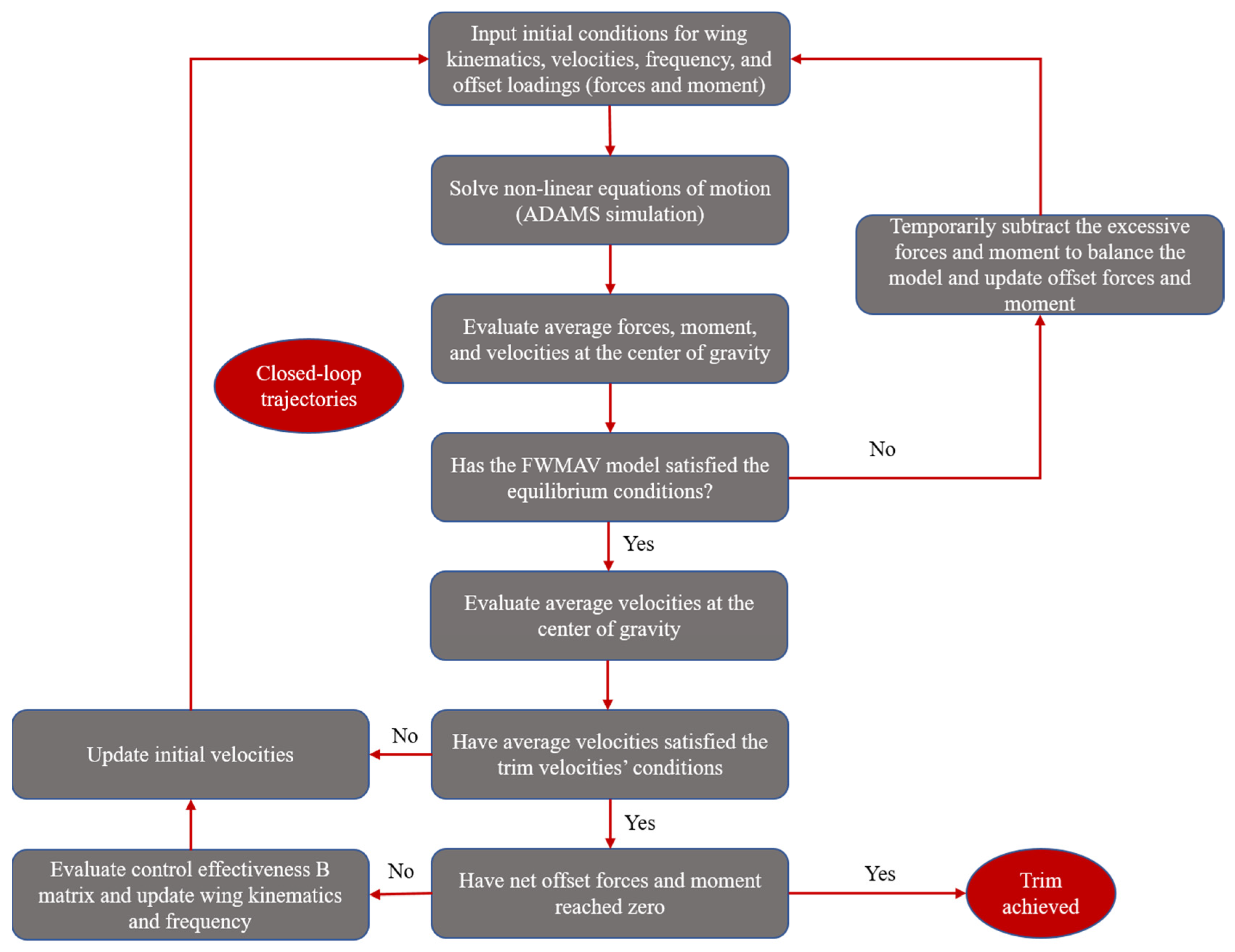
Here u, v, and w denote the translational velocities, and p, q, and r denote the rotational velocities. Moreover, the subscript not-notation (like uo) represents equilibrium values in the text. The trim search algorithm is represented in Figure 4.
During the whole trim process, the flapping frequency fo, the stroke positional angle ϕo, and the angle of rotation αo are searched until the trim is achieved. Firstly, the initial conditions for wing kinematics, flapping frequency, velocities, and offset loadings (forces and moment) are input to the system. The trim search algorithm only accounts for longitudinal direction forces, moment, and states because non-equilibrium lateral dynamics does not exist, keeping in view the symmetric motion of the wings. Then, the simulation starts and the averaged longitudinal motion forces and pitching moment along with the averaged longitudinal motion linear and angular velocities are evaluated. These averaged forces and moment values are compared to the equilibrium conditions, and if they are greater than the specified error tolerance, the excessive forces and moment are evaluated and subtracted temporarily to balance the system. Then, offset forces and moments are updated to compensate for these differences and a new simulation starts. Otherwise, the averaged velocities are evaluated and compared to the reference velocities. Again, if the differences of these velocities are greater than the specified error tolerance for the velocities, then the initial velocities are updated, and a new simulation starts.
After each simulation, the offset forces and moment are accumulated to give the net offset forces and moments. If these have reached zero or the specified error tolerance then the trim is achieved; otherwise, the control effectiveness matrix B is evaluated by Equation (15), and the flapping frequency, stroke positional angle, and rotation angle are updated on the basis of Equation (16).
B = [ F ¯ X G f o F ¯ X G ϕ o F ¯ X G α o F ¯ Z G f o F ¯ Z G ϕ o F ¯ Z G α o M ¯ Y G f o M ¯ Y G ϕ o M ¯ Y G α o ]
[ Δ f o Δ ϕ o Δ α o ] r = B 1 [ Δ F ¯ x G Δ F ¯ z G Δ M ¯ y G ] r , [ f o ϕ o α o ] r + 1 = [ f o ϕ o α o ] r + [ Δ f o Δ ϕ o Δ α o ] r
Here, F ¯ X G and F ¯ Z G represent the net offset forces (equivalent to the accumulated excess forces), and M ¯ Y G is the mean aerodynamic pitching moment (equivalent to the accumulated excess moment) at the center of the gravity. From the gradient of the longitudinal motion forces and moment with respect to the changes in the wing kinematics (Equation (15)), we can evaluate the required changes in wing kinematics to compensate for the excess forces and moment that are misbalancing the system dynamics by calculating the inverse of control effectiveness matrix B as shown in Equation (16). The subscript r and r + 1 represent the rth and (r + 1)th iterations, respectively. As the new simulation starts, the accumulated forces and moments are set to zero. It is noteworthy that this algorithm considers the aerodynamics–dynamics coupling during the convergence process for trim evaluation.

2.4. Equations of Motion and Linearization

The longitudinal dynamics 3-DOF equations of motion are now derived for the FWMAV for controller design in next section. Although the multibody dynamics simulation model developed in Section 2.3 is a nonlinear model considering wing inertia, the model is simplified in this section only for eigenmode analysis and linear controller design. LTI model can be obtained by ignoring the wing inertia and averaging. It is important to note that the multibody dynamics simulation is still used for calculating stability derivatives of the LTI model. By assuming ignorable mass of the wings, neglecting the mean inertial forces and moments during up and down strokes that cancel each other due to symmetric nature of wing kinematics and using wingbeat cycle averaged approach, we derived the equations of motion on the basis of standard aircraft’s model [68] and are expressed in body coordinate system as follows:
X m s g sin Θ = m s ( u ˙ + q w ) Z + m s g cos Θ = m s ( w ˙ q u ) M = I y y q ˙
Here, ms is the total mass of the FWMAV, and X, Z, and M represent the periodic aerodynamic forces and moment because of the periodic motion of the wings.
To evaluate the dynamic stability of the FWMAV system and to design and implement a controller on it, we linearized the nonlinear equations of motion by utilizing small perturbation theory as per Nelson [68]. For linearization, nonlinear value can be converted to the sum of trim reference (wingbeat cycle averaged) value and a small perturbation about it as follows:
u ¯ = u ¯ o + Δ u ¯ , w ¯ = w ¯ o + Δ w ¯ , q ¯ = q ¯ o + Δ q ¯ u ˙ ¯ = u ˙ ¯ o + Δ u ˙ ¯ , w ˙ ¯ = w ˙ ¯ o + Δ w ˙ ¯ , q ˙ ¯ = q ˙ ¯ o + Δ q ˙ ¯ , Θ ¯ = Θ ¯ o + Δ Θ ¯ X ¯ = X ¯ o + Δ X ¯ , Z ¯ = Z ¯ o + Δ Z ¯ , M ¯ = M ¯ o + Δ M ¯
Here, for satisfying the trim conditions, we can assume that u ˙ ¯ o = 0 , w ˙ ¯ o = 0 , q ˙ ¯ o = 0 , and q ¯ o = 0 . Moreover, u ¯ o 0 and w ¯ o 0 because of the forward flight speed and up/down motion in the body coordinate system. Using previously discussed assumptions and previous equations, we obtain Equation (19).
Δ X ¯ m s g cos Θ ¯ o Δ Θ ¯ = m s [ Δ u ˙ ¯ + w ¯ o Δ q ¯ ] Δ Z ¯ m s g sin Θ ¯ o Δ Θ ¯ = m s [ Δ w ˙ ¯ u ¯ o Δ q ¯ ] Δ M ¯ = I y y Δ q ˙ ¯
As the aerodynamic forces and moment are dependent upon the dynamic variables, their changes can therefore be written as sum of aerodynamic derivatives as per Nelson [68]. These aerodynamic forces’ and moments’ derivatives with respect to dynamic variables are expressed in Equation (20).
X ¯ u ¯ = X ¯ u ¯ ,   X ¯ w ¯ = X ¯ w ¯ ,   X ¯ q ¯ = X ¯ q ¯ , Z ¯ u ¯ = Z ¯ u ¯ ,   Z ¯ w ¯ = Z ¯ w ¯ ,   Z ¯ q ¯ = Z ¯ q ¯ , M ¯ u ¯ = M ¯ u ¯ ,   M ¯ w ¯ = M ¯ w ¯ ,   M ¯ q ¯ = M ¯ q ¯
Using Equation (20), the aerodynamic forces and moment terms in Equation (19) can be written as follows:
Δ X ¯ = X ¯ u ¯ Δ u ¯ + X ¯ w ¯ Δ w ¯ + X ¯ q ¯ Δ q ¯ Δ Z ¯ = Z ¯ u ¯ Δ u ¯ + Z ¯ w ¯ Δ w ¯ + Z ¯ q ¯ Δ q ¯ Δ M ¯ = M ¯ u ¯ Δ u ¯ + M ¯ w ¯ Δ w ¯ + M ¯ q ¯ Δ q ¯
After substituting the aerodynamic forces and moment terms in Equation (19) and rearranging, we obtain the following standard state-space form of our 3-DOF longitudinal FWMAV system (Equation (22)) [44,45]. This model is used for the controller design and implementation.
[ Δ u ˙ ¯ Δ w ˙ ¯ Δ q ˙ ¯ Δ q ¯ ] = [ X ¯ u ¯ m s X ¯ w ¯ m s X ¯ q ¯ m s w ¯ o g Z ¯ u ¯ m s Z ¯ w ¯ m s Z ¯ q ¯ m s + u ¯ o 0 M ¯ u ¯ I y y M ¯ w ¯ I y y M ¯ q ¯ I y y 0 0 0 1 0 ] [ Δ u ¯ Δ w ¯ Δ q ¯ Δ Θ ¯ ]
For longitudinal dynamic stability characterization, the nondimensionalization of Equation (22) is carried out as per Equation (23).
m s + = m s ρ U S T ,   g + = g T U ,   I y y + = I y y ρ U 2 S w c ¯ T 2 Δ u + = Δ u U ,   Δ w + = Δ w U ,   Δ q + = Δ q T X u + = X u ρ U S w ,   X w + = X w ρ U S w ,   X q + = X q ρ U S w c ¯ ,   Z u + = Z u ρ U S w ,   Z w + = Z w ρ U S w ,   Z q + = Z q ρ U S w c ¯ , M u + = M u ρ U S w c ¯ ,   M w + = M w ρ U S w c ¯ ,   M q + = M q ρ U 2 S w c ¯ T
Here, U is the reference velocity given by 2 f r 2 ϕ a m p , T is 1/f or wingbeat cycle period, c ¯ is the mean chord, and ρ is the air density. The nondimensionalized 3-DOF equations of motion for stability study is expressed in Equation (24), where A+longitudinal is system’s matrix in longitudinal direction.
[ Δ u ˙ + Δ w ˙ + Δ q ˙ + Δ q ] = A l o n g i t u d i n a l + [ Δ u + Δ w + Δ q + Δ Θ ] = [ X u + m s + X w + m s + X q + m s + w o + g + Z u + m s + Z w + m s + Z q + m s + + u o + 0 M u + I y y + M w + I y y + M q + I y y + 0 0 0 1 0 ] [ Δ u + Δ w + Δ q + Δ Θ ]

2.5. Augmented LQR Controller Design for Transition Flight Tracking

In this section, augmented LQR control method is discussed in terms of obtaining the optimal gain matrices for controlling both the linear and nonlinear FWMAV models involving various flight speeds for performing different maneuvers.

2.5.1. Gain-Scheduled LQR Controller Design for Linear System

The trim conditions are obtained for various forward flight speeds. At each trim condition, the linearized FWMAV equations are obtained and expressed as Equation (22). The standard state-space form for the linearized system along with the normalized control effectiveness matrix is shown in Equation (25), and it is obtained for trim conditions at each forward flight speed. The simplified version is shown in Equation (26), and the output is shown in Equation (27). The schematics of the control implementation for the linear system for reference velocity profile tracking in the transition flight of FWMAV is shown in Figure 5. The block model shown in Figure 5 uses a gain-scheduled optimal LQR controller based on forward flight speed that must account for the time-varying dynamic behavior of the nonlinear FWMAV model.
[ Δ u ˙ ¯ Δ w ˙ ¯ Δ q ˙ ¯ Δ q ¯ ] = [ X ¯ u ¯ m s X ¯ w ¯ m s X ¯ q ¯ m s w ¯ o g Z ¯ u ¯ m s Z ¯ w ¯ m s Z ¯ q ¯ m s + u ¯ o 0 M ¯ u ¯ I y y M ¯ w ¯ I y y M ¯ q ¯ I y y 0 0 0 1 0 ] [ Δ u ¯ Δ w ¯ Δ q ¯ Δ Θ ¯ ] + [ F ¯ X G f o / m s F ¯ X G ϕ o / m s F ¯ X G α o / m s F ¯ Z G f o / m s F ¯ Z G ϕ o / m s F ¯ Z G α o / m s M ¯ Y G f o / I y y M ¯ Y G ϕ o / I y y M ¯ Y G α o / I y y ] [ Δ f o Δ ϕ o Δ α o ]
X ˙ = [ Δ u ˙ ¯ Δ w ˙ ¯ Δ q ˙ ¯ Δ q ¯ ] = A [ Δ u ¯ Δ w ¯ Δ q ¯ Δ Θ ¯ ] + B c [ Δ f o Δ ϕ o Δ α o ] X ˙ = A X + B c u c
Y = [ Δ u ¯ G Δ w ¯ G Δ Θ ¯ ] = [ cos Θ r sin Θ r 0 0 sin Θ r cos Θ r 0 u o 0 0 0 1 ] [ Δ u ¯ Δ w ¯ Δ q ¯ Δ Θ ¯ ] = C X Y = C X + D u C = C X
where A is the system matrix, Bc is the normalized control effectiveness matrix that is obtained from the gradient-based trim search algorithm, uc is the control input, Y is the output (perturbations in velocities and body pitch angle in global coordinate system), the matrix output is C, D is the zero matrix, and the state variables are expressed as X. Here, Θ r is the reference body pitch angle during each of the trimmed state.
Figure 5 shows that there is an integral action applied in the control implementation. The error in the velocities and the body pitch angle are passed through the integral action for removing any steady-state error that can compensate for any uncertainty in the system. The states, which are defined as differences from their references, themselves can be used as error estimation; therefore, an augmented state-space form of the equations of motion are written using integral states with over-curved notation. The subscript r denotes the reference states in Equation (28) for the system output equation. The augmented state-space form of the system is represented as Equation (29).
Y = X ˙ I = [ u ¯ u ¯ r w ¯ w ¯ r Θ ¯ Θ ¯ r ] G   X I = 0 t Y d t
X ˙ = [ X ˙ X ˙ I ] = [ A 0 C 0 ] [ X X I ] + [ B c 0 ] u c = A X + B c u c X ˙ = A X + B c u c
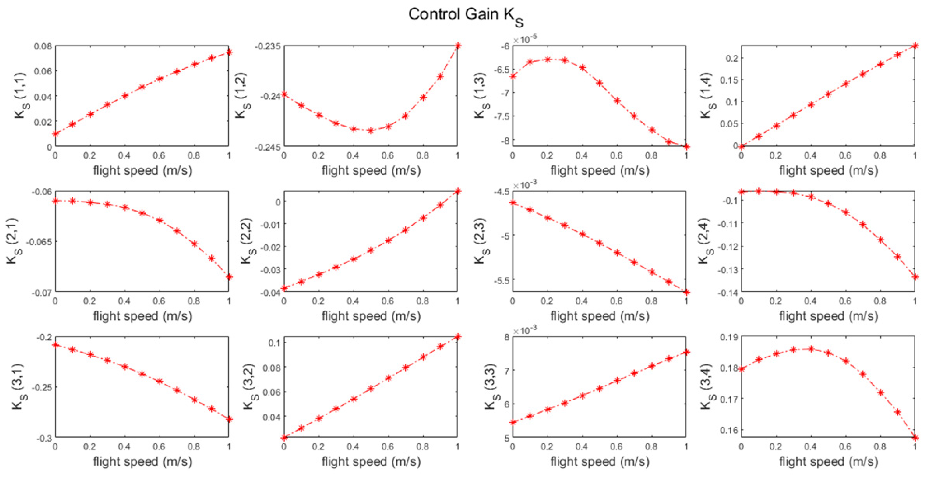
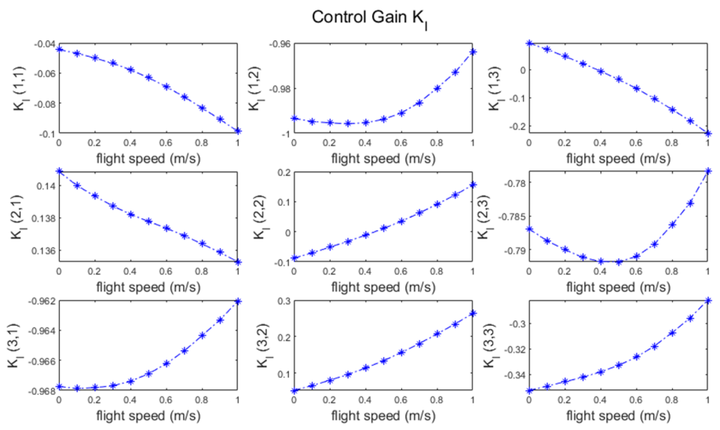
The LQR optimal control determines the control gain K [3 × 7], which is split into the gains KS [3 × 4] and KI [3 × 3] for the system states and the integral states, respectively, for the augmented full state feedback controller design. The LQR method optimizes the solution by minimizing the cost function J as shown in Equation (30) and as discussed in [69]. The optimal gain matrices K and the matrix P are determined by solving the algebraic Riccati equation (ARE), as shown in Equation (31). For each forward flight speed, different gain matrices are calculated and then input to the feedback control loop for the longitudinal flight control involving varying forward speed references. The gain matrices at various flight speeds for FWMAV control are shown in Figure 6 and Figure 7. The input matrix related to the augmented system is shown in Equation (32).
cost   function   = J min = 0 ( X T Q X + u c T R u c ) d t
K = R 1 B c T P A R E = A T P + P A P B c R 1 B c T P + Q
u c = K X = [ K S K I ] [ X X I ] = K S X K I X I = u S + u I
where Q and R are the weighting matrices for the flight states and the inputs, respectively, that are adjusted by trial and error. In addition, X and integral of XI are eS and eI, respectively, as shown in Figure 5. As per another study [70], LQR optimal problem must satisfy some criteria, such as Q matrix having to be positive semidefinite, R matrix being strictly positive definite, and P matrix being unique and positive semidefinite.

2.5.2. Gain-Scheduled LQR Controller Design for Nonlinear System

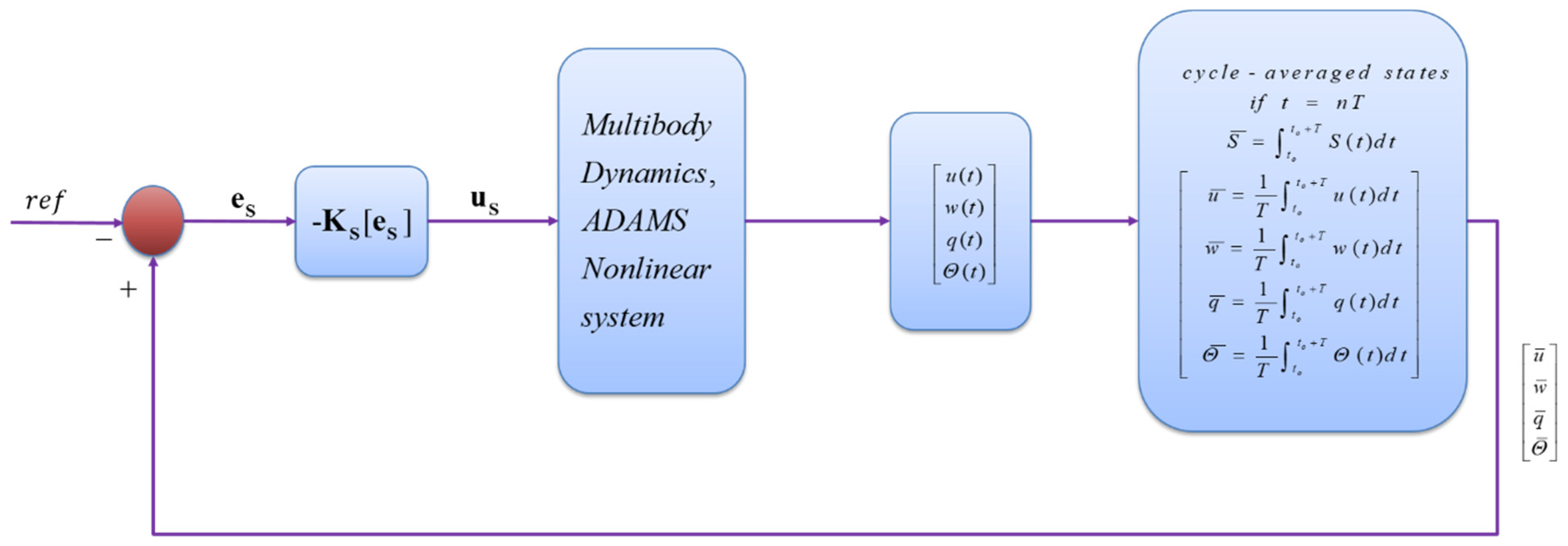
The multibody dynamics simulation framework discussed in Section 2.3.1 is appended with the flight control block as shown in Figure 8 for controlling the nonlinear FWMAV model. The flight states come from the nonlinear model and the control inputs go into it in order to track the reference states. As the nonlinear FWMAV model involves changing dynamics within each flapping cycle, the system dynamic variables must be averaged after each flapping cycle to compare them with reference states and track them. The schematic diagram of the basic control implementation methodology adopted is shown in Figure 9 for stabilizing hovering and forward flight conditions. The designed LQR controller in the previous section is implemented for the nonlinear model. In Figure 9, T is the wingbeat cycle time period, N indicates the number of flapping cycles, S represents any state, and the simulation time is represented by t.
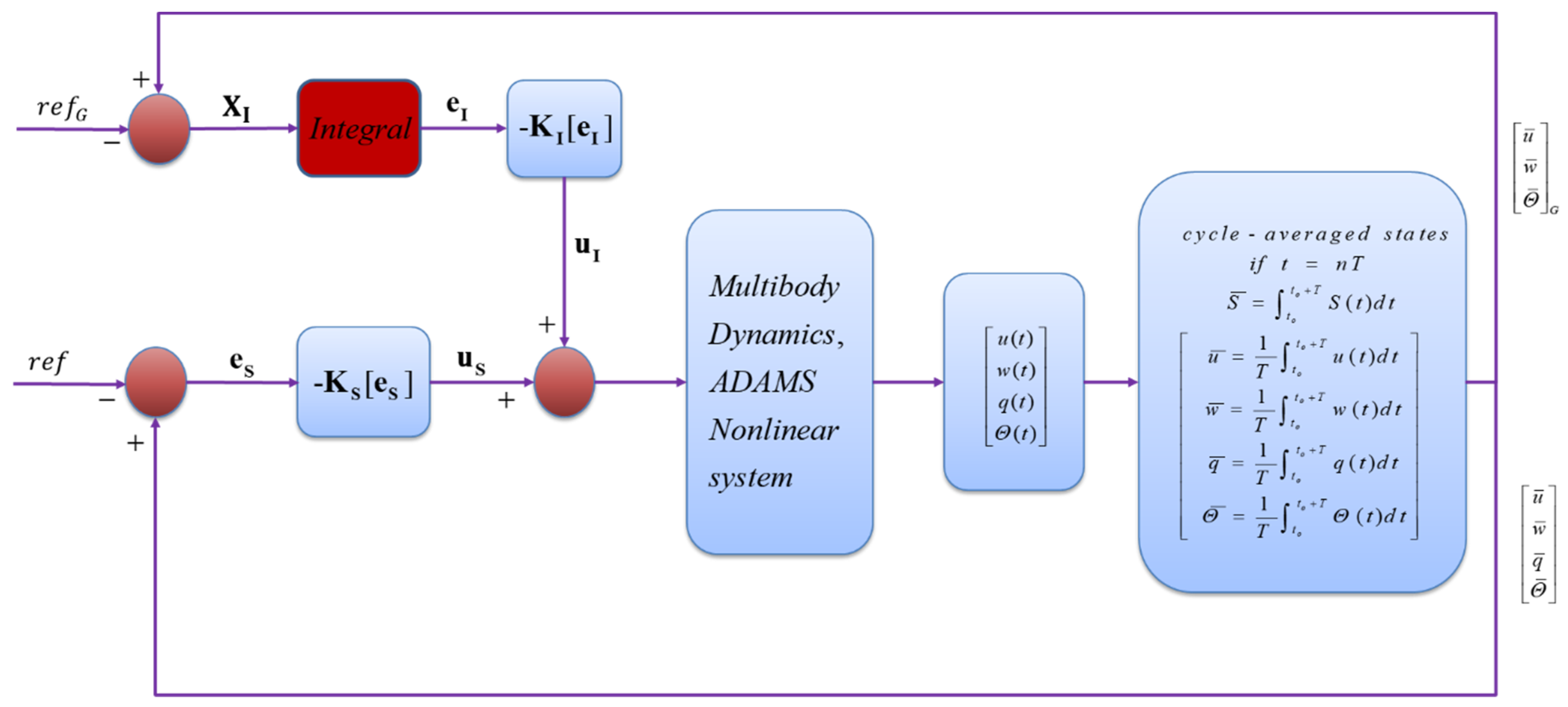
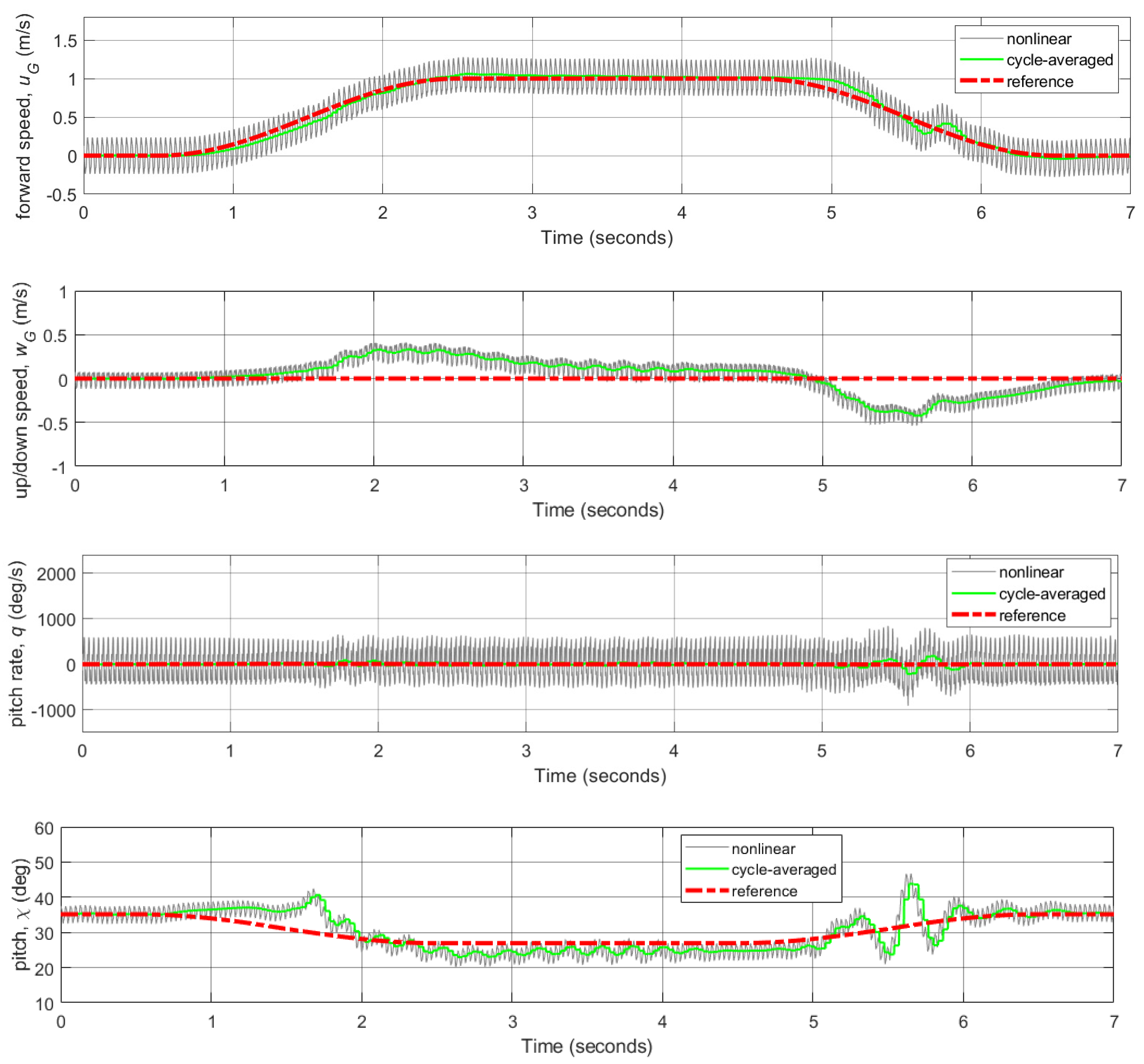
Figure 10 shows the controller design for tracking the transition flight for the nonlinear multibody FWMAV model, involving various phases such as hovering, acceleration, constant speed, deceleration, and hovering again. The multibody FWMAV system makes the control problem more realistic but challenging too as the wings–body interaction dynamics come into play. The cycle-averaged approach is adopted for this nonlinear system as our linearized model is based on wing-beat cycle-averaged states of the system.
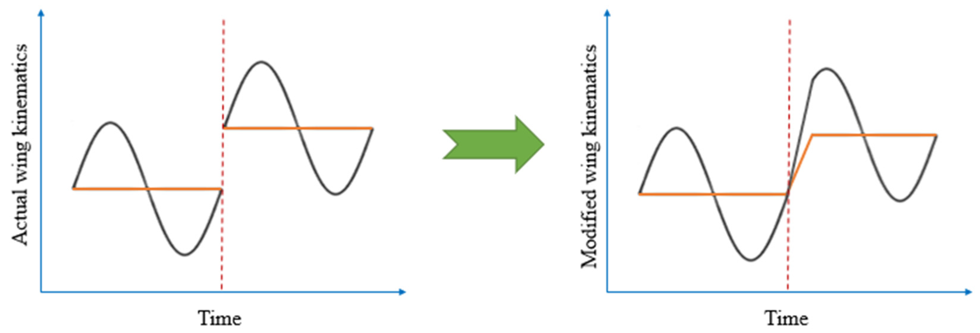
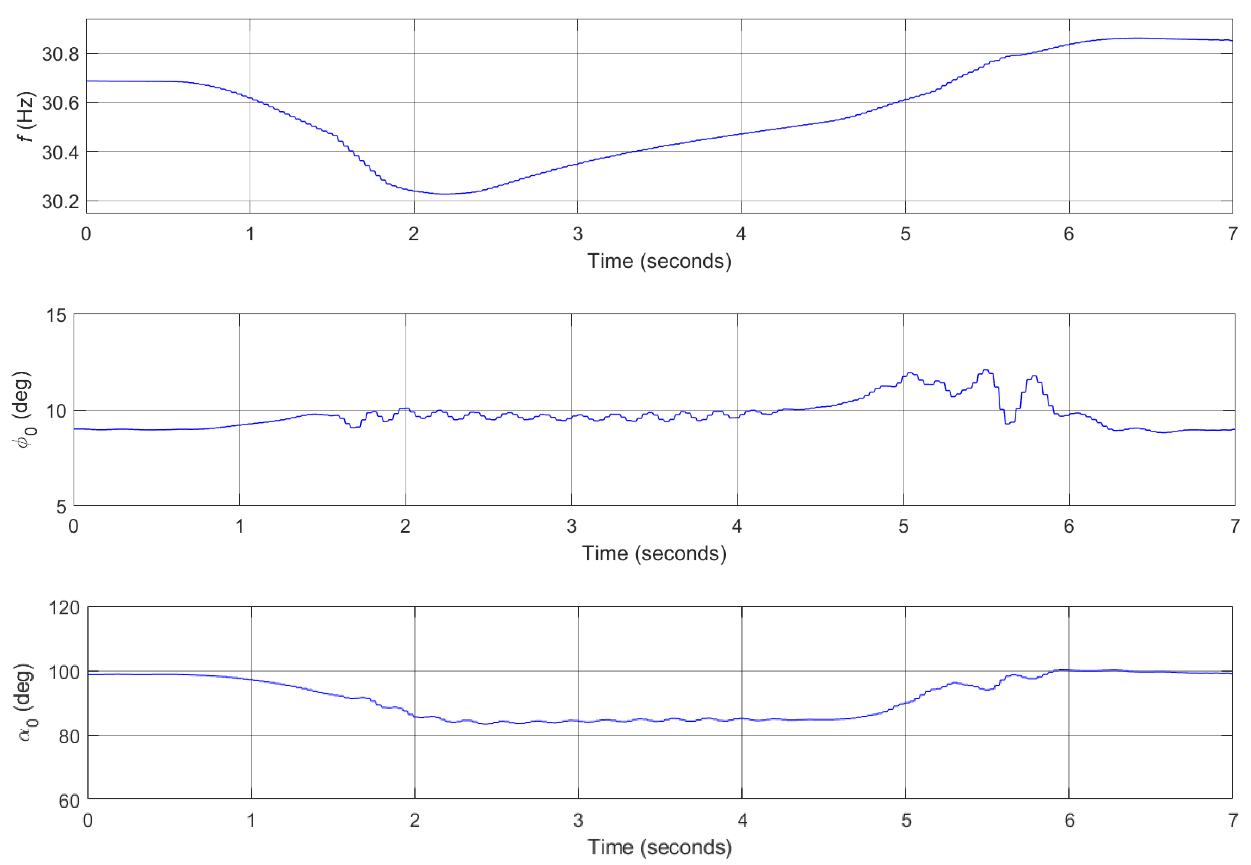
As the states are changing at every instant for this nonlinear model, the control inputs such as flapping frequency, mean/averaged stroke positional angle, and mean/averaged rotational/feathering angle are also changing at every instant. This results in discontinuity in the control inputs after each flapping cycle as shown in the left picture of Figure 11. In order for this discontinuity to be avoided, the control inputs (flapping frequency and wing kinematics) are updated continuously to obtain the modified control inputs that are continuous as shown in the right picture of Figure 11. Here, black and orange lines indicate the time-varying control inputs and the averaged control inputs, respectively. These continuous mean/averaged control inputs change smoothly between each flapping cycle.

2.6. Trajectory Tracking Controller Design

As will be shown in Section 3.3, the forward flight velocity tracking along with the other reference states tracking work very well. Since the velocity command can be followed promptly, obtaining the position from it and minimizing the position error can help in tracking various trajectories if the FWMAV system is made fully observable. Therefore, a dual loop approach is adopted as shown in Figure 12 to track given trajectories in x and z positions. The subscript r with different states depict the references for the states being tracked in Figure 12. For position control, a PI controller is appended to the already designed velocity controller. Here, the PI controller (outer loop) is designed, utilizing positions’ errors to generate suitable velocities’ references. The velocities’ references are then tracked by the velocity controller (inner loop), and this cyclic process goes on as the respective positions in x and z directions are being tracked. The P and I gains are selected for each direction as Px = 5.5, Ix = 0.3, Pz = 30, and Iz = 6. Several simulations are run to obtain these appropriate P and I gains in xG and zG directions that can track the reference trajectories efficiently. For this study, three arbitrary trajectories, each having x (horizontal) and z (vertical) positions with increasing level of complexity, are chosen in the global coordinate system to check the effectiveness of the designed controller.

3. Results and Discussion

3.1. Stability Characterization of Longitudinal Dynamics

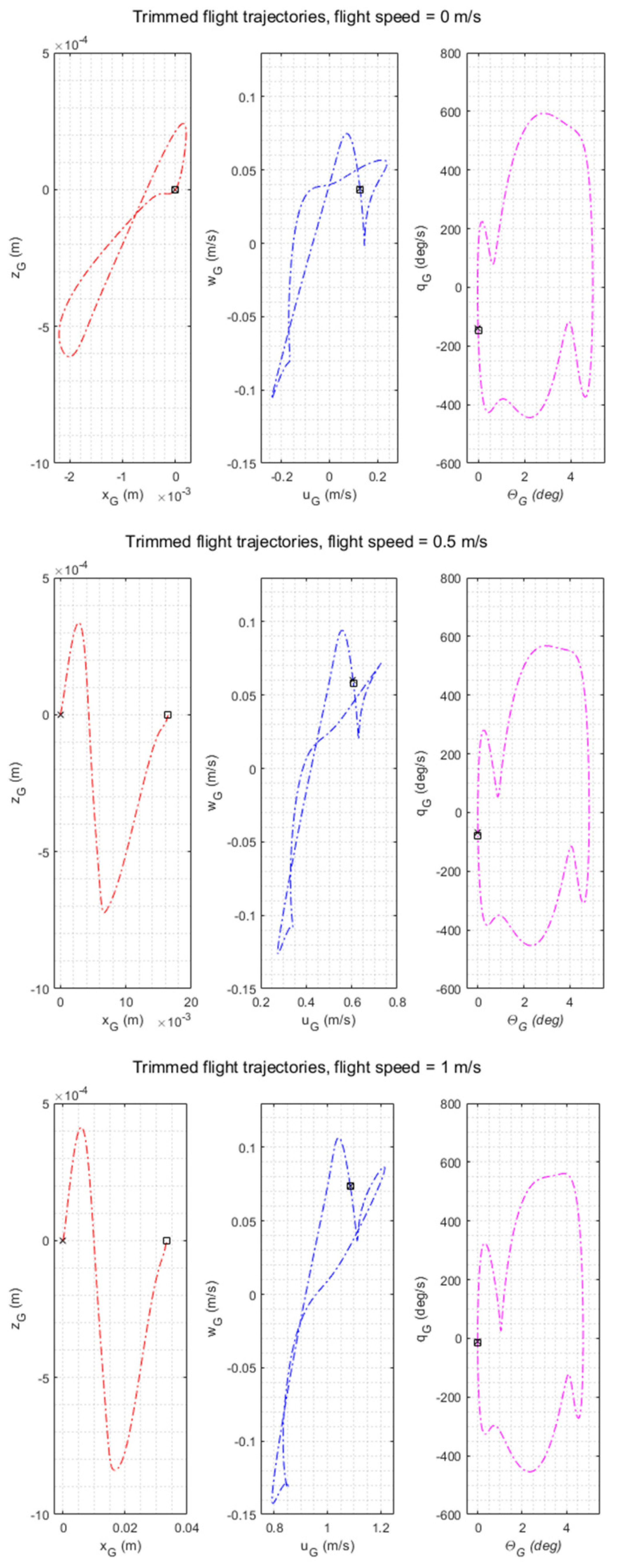
This section details the effect of simplified wing kinematics on longitudinal dynamics of FWMAV in hovering and forward flight, as this wing kinematics is suitable for practical control implementation purposes. Using simplified wing kinematics, we employed the gradient-based trim search algorithm to find the trim conditions for various flight speeds from 0 m/s to 1 m/s, which satisfies the trim criteria as discussed in Section 2.3.2. Although real hawkmoths can fly faster than 1 m/s [71], this study focused on the speed range (0–1 m/s) in view of the limitation in our computation resource for iterative trim search. In addition, we considered this flight range to be critical since it is inevitable to transit from hovering to forward flight without passing through this range. Table 2 summarizes the results of trim flight conditions that include trimmed flapping frequency, stroke positional angle, and rotational angle that are utilized for controller design and implementation. Body pitch angles at each forward flight speed are used as references for stabilizing fixed flight conditions, transition flight tracking, and reference trajectories tracking. Figure 13 shows time domain trim flight trajectories at 0 m/s, 0.5 m/s, and 1 m/s flight speeds for respective states of center of gravity (CG) in global coordinate system. In the hovering case, all variables in phase portraits depicted closed-loop trimmed trajectories, while in forward flight (0.5 m/s and 1 m/s), xG values started to increase because of increase in flight speed. The starting points and ending points of states are shown by green squares and black asterisks, respectively. In all cases, initial and end states were fairly close, except for position states (xG vs. zG) in forward flight, which clearly showed that FWMAV oscillated around the equilibrium values and maintained those mean trim values in stable conditions.
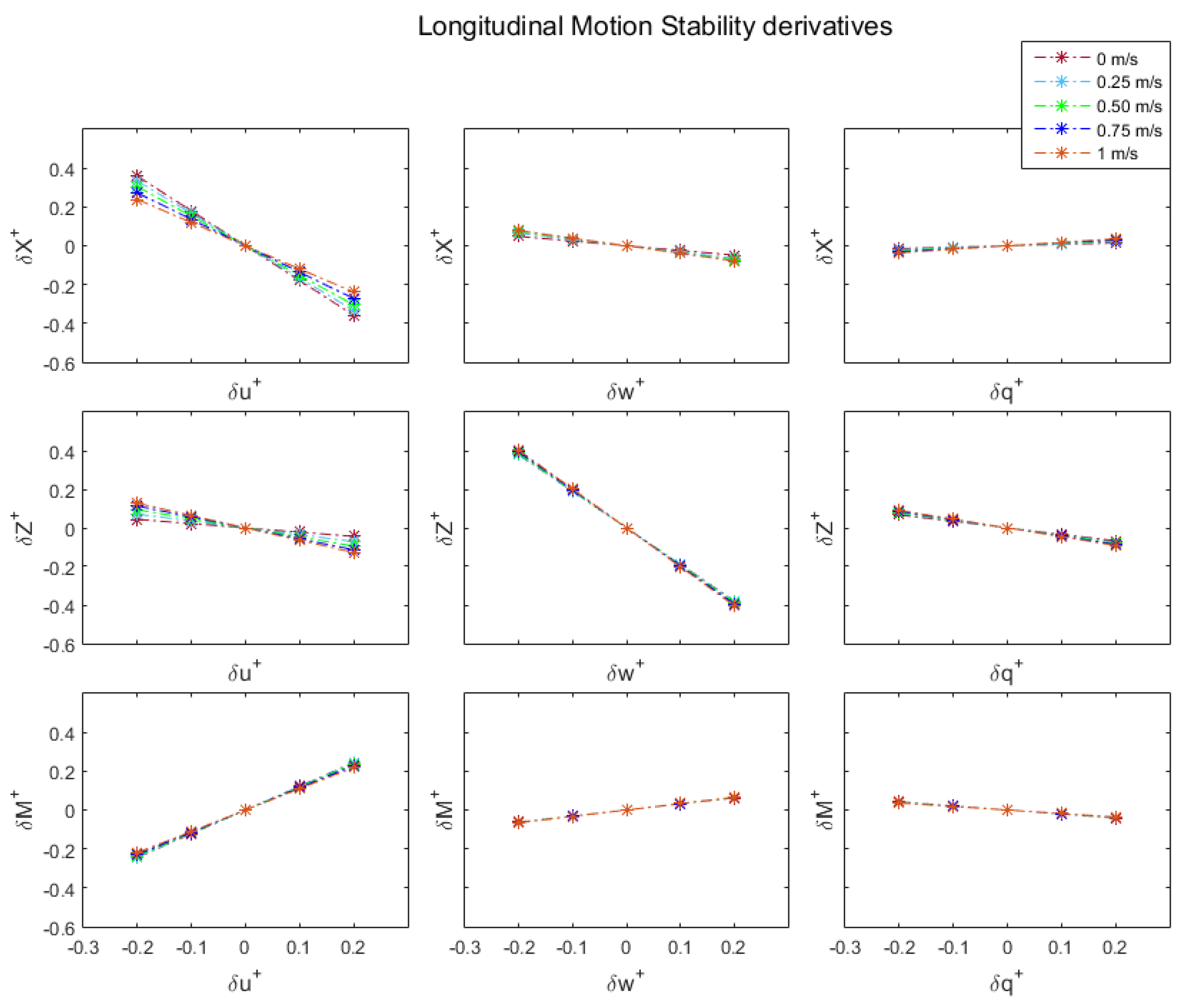
Figure 14 shows the nondimensionalized longitudinal motion stability derivatives that form the part of system matrices to characterize the dynamic stability of the FWMAV. For the longitudinal motion stability derivatives, the larger values of slopes (big negatives) or effectual derivatives were the Xu+ and Zw+; therefore, the longitudinal motion would be more damped regarding these degrees of freedom. In contrast, with the increase in flight speed the damping effect of Xu+ decreased, and the damping effect of Zw+ increased slightly. Other derivatives that can be effective in longitudinal motion damping were Mq+, Xw+, and Zq+, as shown in Figure 14.
The longitudinal motion eigenvalues for simplified wing kinematics at various flight speeds are shown in Figure 15. On the leftmost side, there is a stable fast subsidence mode 1 showing negative real eigenvalues. These values became more negative at higher speeds, indicating better passive stability at higher speeds. In the middle, there was a stable slow subsidence mode 2, and it can be seen that this mode destabilized the system at higher speeds because the real negative eigenvalues were shifting towards zero. Finally, we can see the unstable oscillatory mode 3, which is a pair of complex numbered eigenvalues with a positive real part. It can be seen that with the increase in forward flight speed, the positive real value of this mode started to increase and resulted in more instability at higher speeds. For hovering, previous studies [19,46] have shown one stable fast subsidence mode, one stable slow subsidence mode, and an unstable oscillatory mode that qualitatively matched to the behavior of our model’s response in hovering as shown in Figure 15. In addition, Kim et al. [45] showed that at higher speeds, the one stable fast subsidence mode, the one stable slow subsidence mode, and the unstable oscillatory modes became more stable, slightly destabilized, and more unstable, respectively. These longitudinal modes’ behaviors were from the measured hawkmoth wing kinematics and agree well with our results.

3.2. Flight Control Simulations for Stabilizing Fixed Flight Conditions

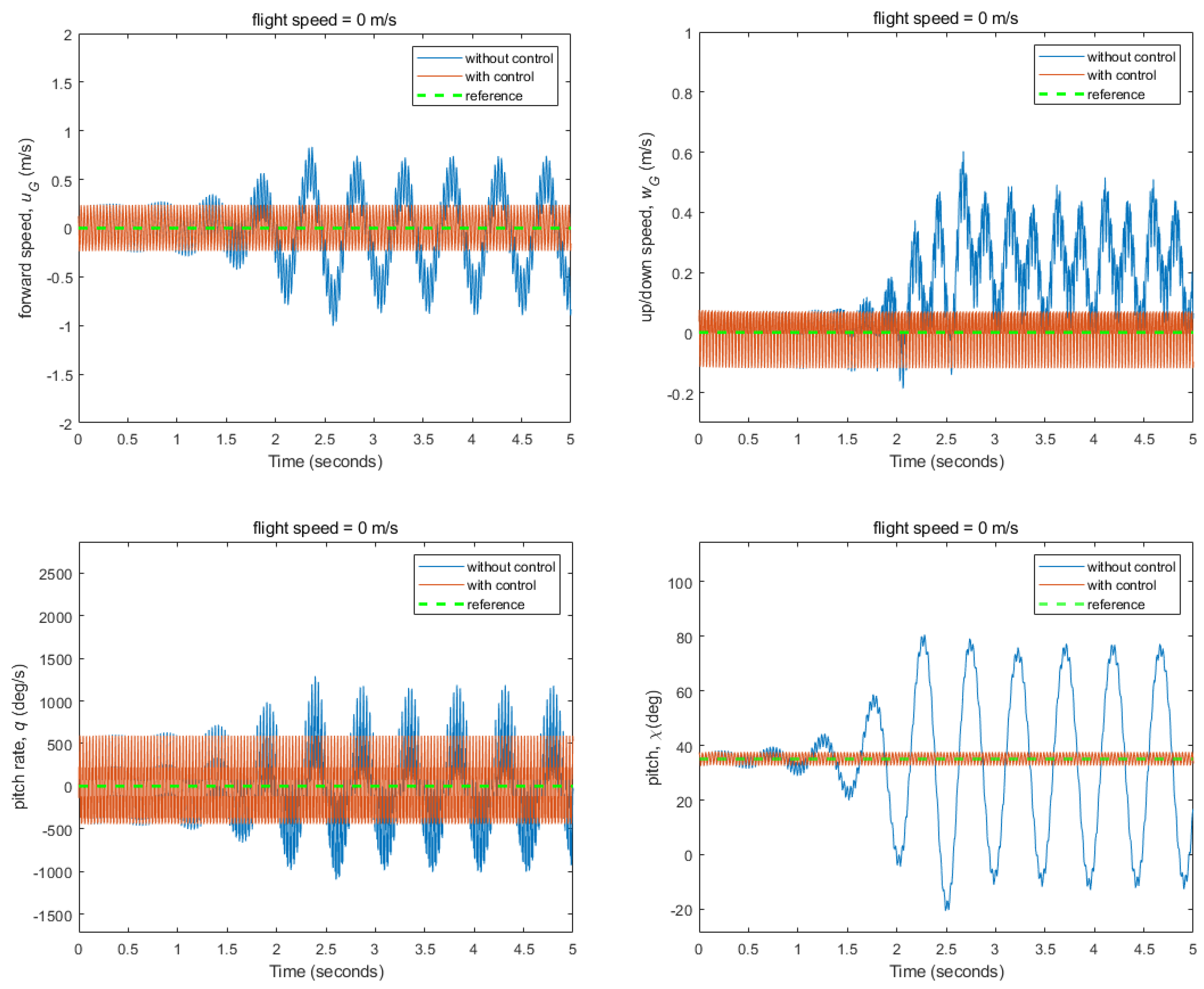
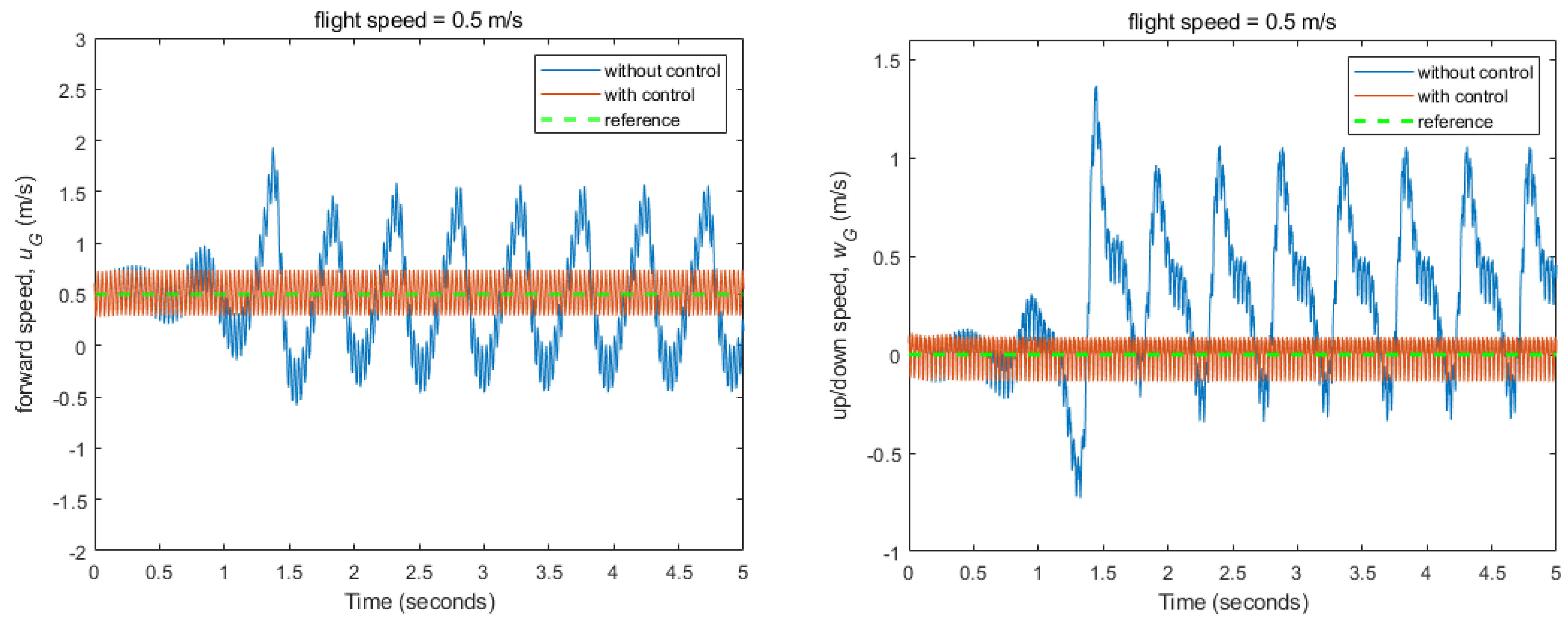
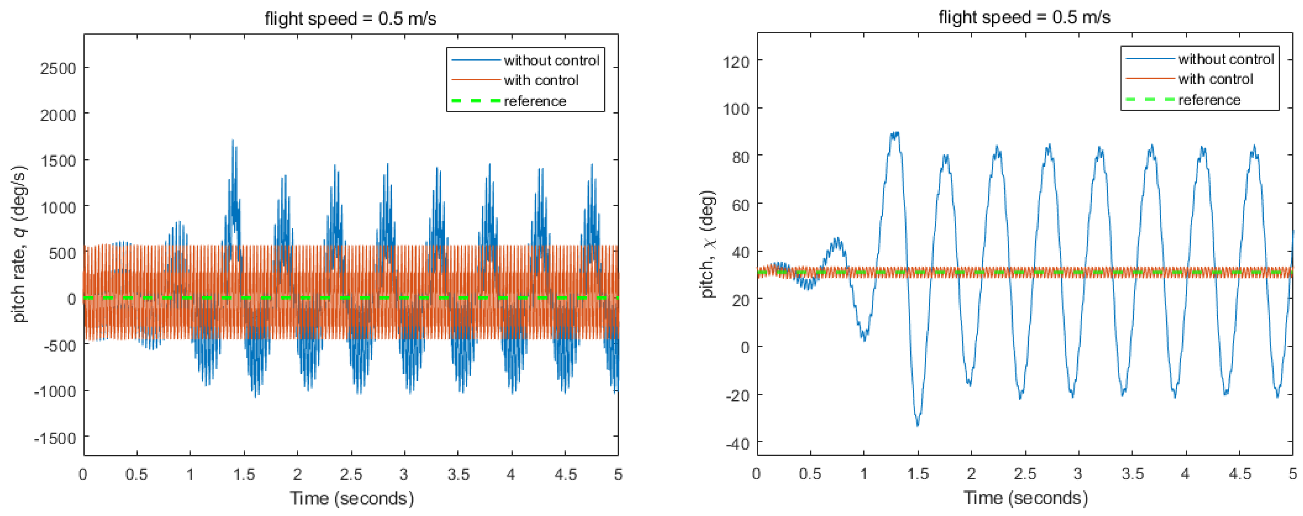
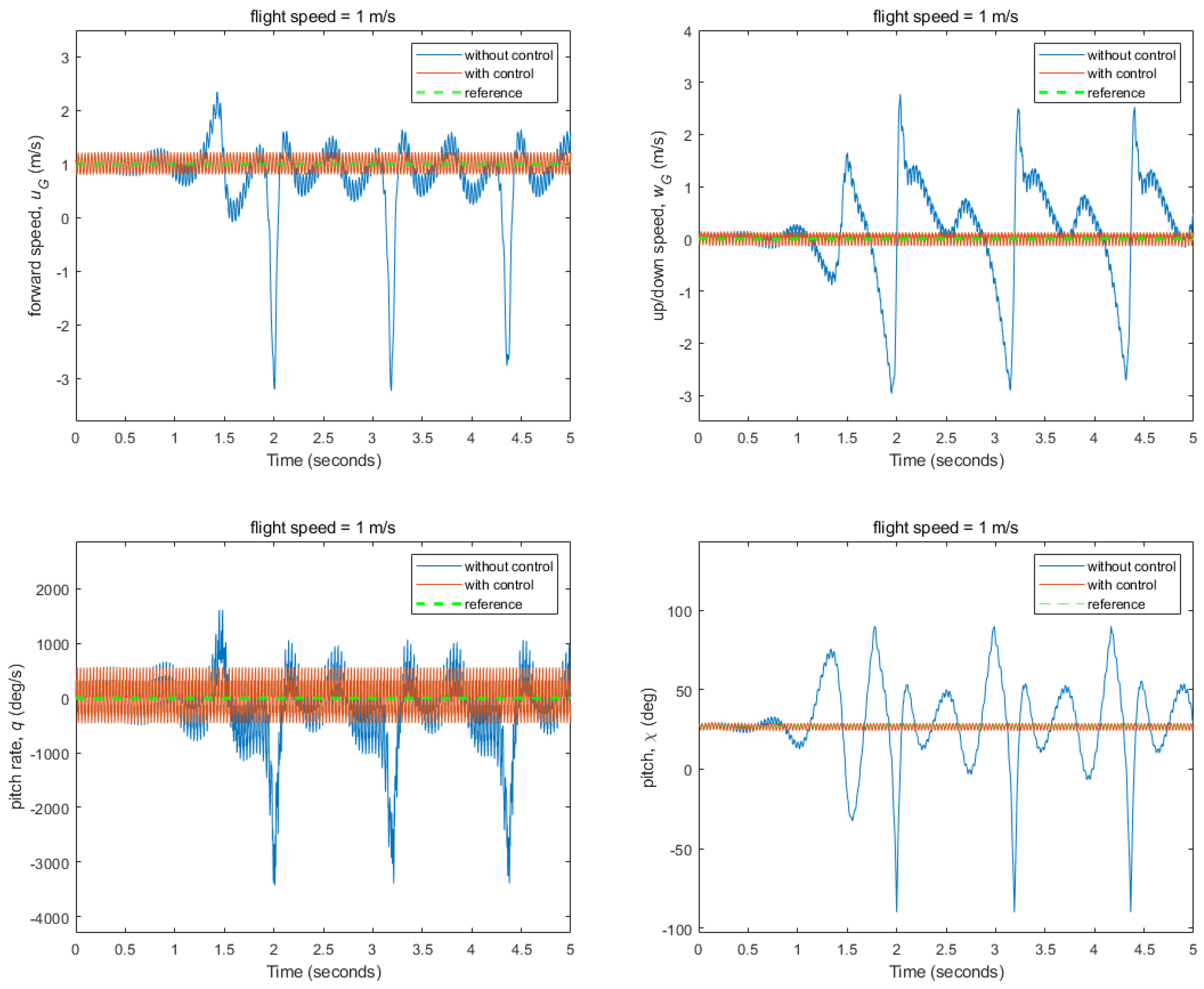
The results for the nonlinear multibody FWMAV flight control to stabilize hovering and forward flight states are shown in Figure 16, Figure 17 and Figure 18 using controller in Figure 9. The simulation results for different cases such as without control, with control, and the reference states are presented. In all simulations, FWMAV was required to move at reference forward speed, zero up/down speed, zero pitch rate, and reference body pitch angle. The instabilities in states increased with the flight speed and made the control problem more challenging. However, overall, it can be seen that the controlled model converged to the reference states within 0.4 s while successfully following all of the required states for a unique set of weighting matrices at different flight speeds with corresponding control gains’ matrices. This would be helpful to obtain an efficient and consistent controller design for the transition flight tracking and reference trajectories tracking of nonlinear model throughout its mission.

3.3. Flight Control Simulations for Transition Flight Tracking

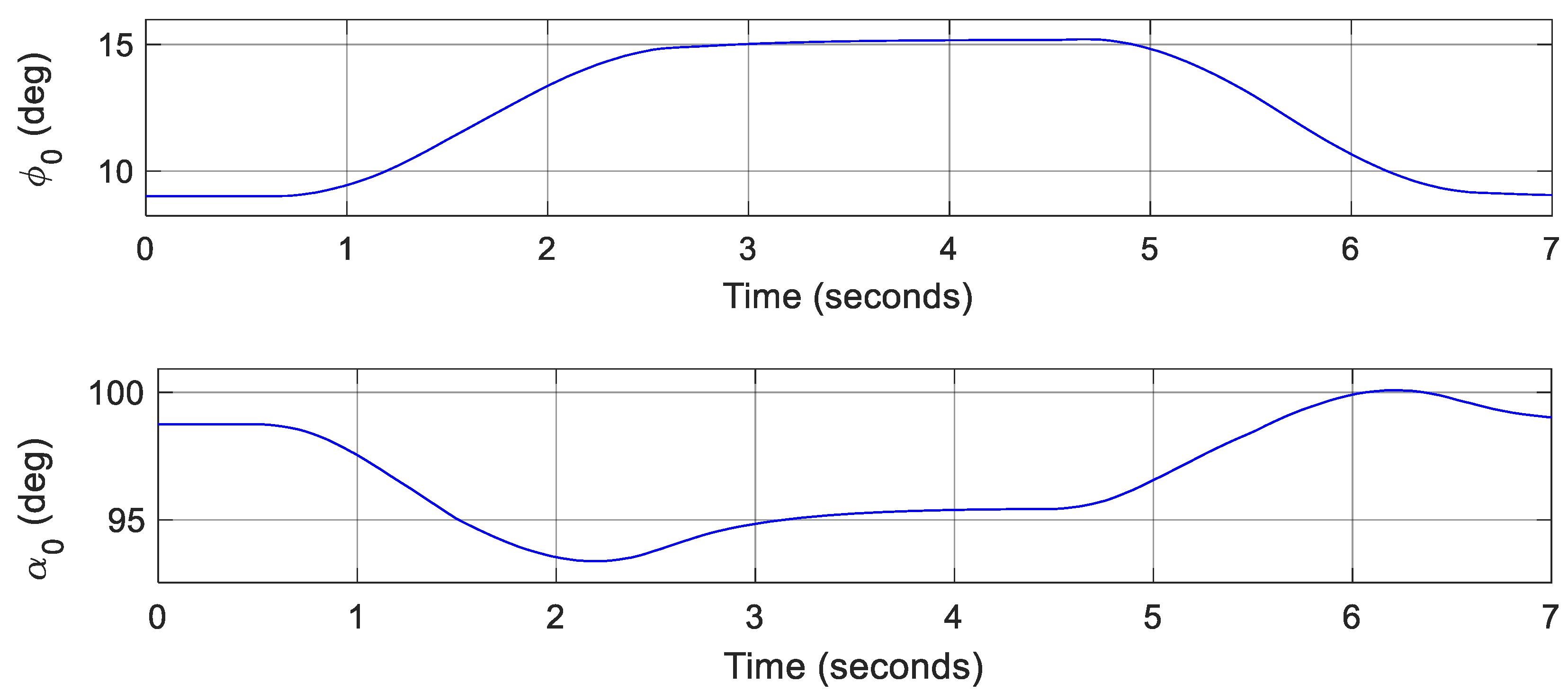
Since the controller maintained the fixed flight conditions very well, it was further evaluated to follow the transition flight conditions for performing various maneuvers using controllers from Section 2.5.2. For this, a reference velocity profile that includes hovering, acceleration, constant speed, deceleration, and hovering again was tracked for both the linear model and nonlinear multibody model. The simulation results and control inputs for linear model are shown in Figure 19 and Figure 20, respectively. It can be seen that all states were tracked efficiently, and the FWMAV accelerated and decelerated each within two seconds. Maintaining constant speeds involved minimal deviation in results; however, in transition flight conditions (acceleration and deceleration), slight deviations from references were reasonable due to rapidly changing body pitch angle and parametrically changing control gains to maintain the performance. The control simulation results and control inputs for nonlinear multibody model are shown in Figure 21 and Figure 22, respectively. All states, forward speed, up/down speed, pitch angle, and pitch rate were tracked well with small deviations during acceleration and deceleration phases only. The reason for these slight deviations during acceleration and deceleration phases was that body pitch angle rapidly changed and control gains were updated continuously for this parametric varying nonlinear system. The control inputs for both the linear and nonlinear models varied smoothly and were within reasonable ranges for transition flight tracking. Even though the control was challenging for this fairly nonlinear multibody system as three inputs were controlling four states simultaneously, the simulation results showed that the designed controller worked effectively to track the reference velocity profile involving hovering, acceleration, constant speed, deceleration, and again hovering phases.

3.4. Flight Control Simulations for Reference Trajectories Tracking

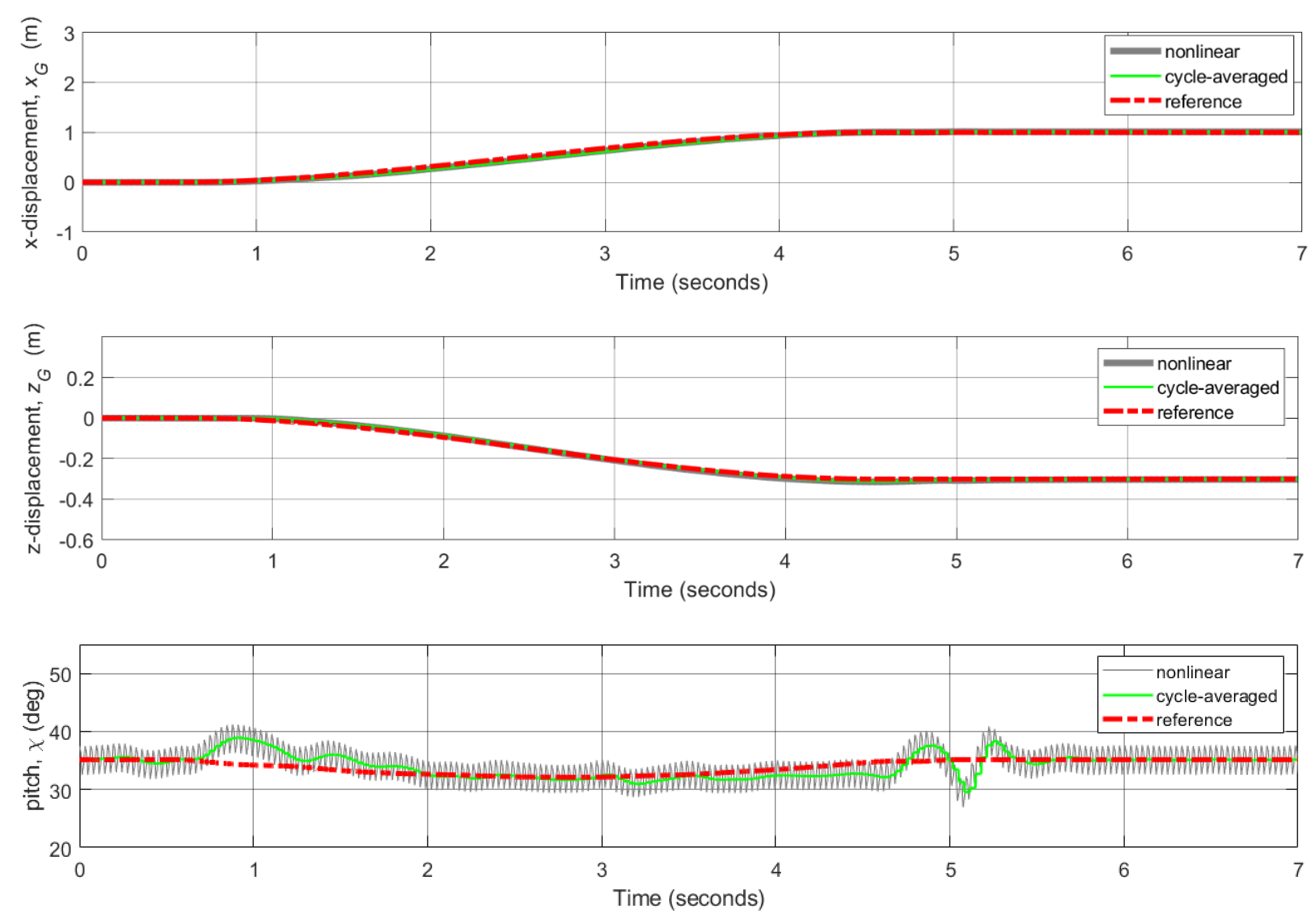
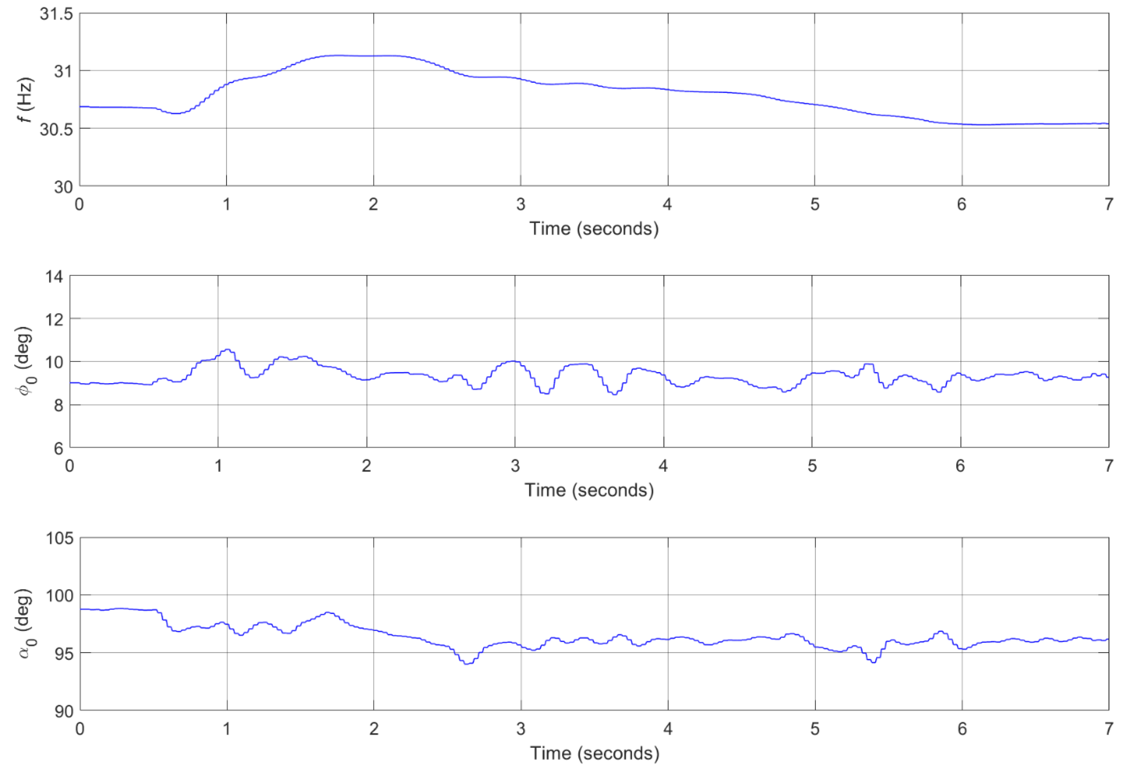
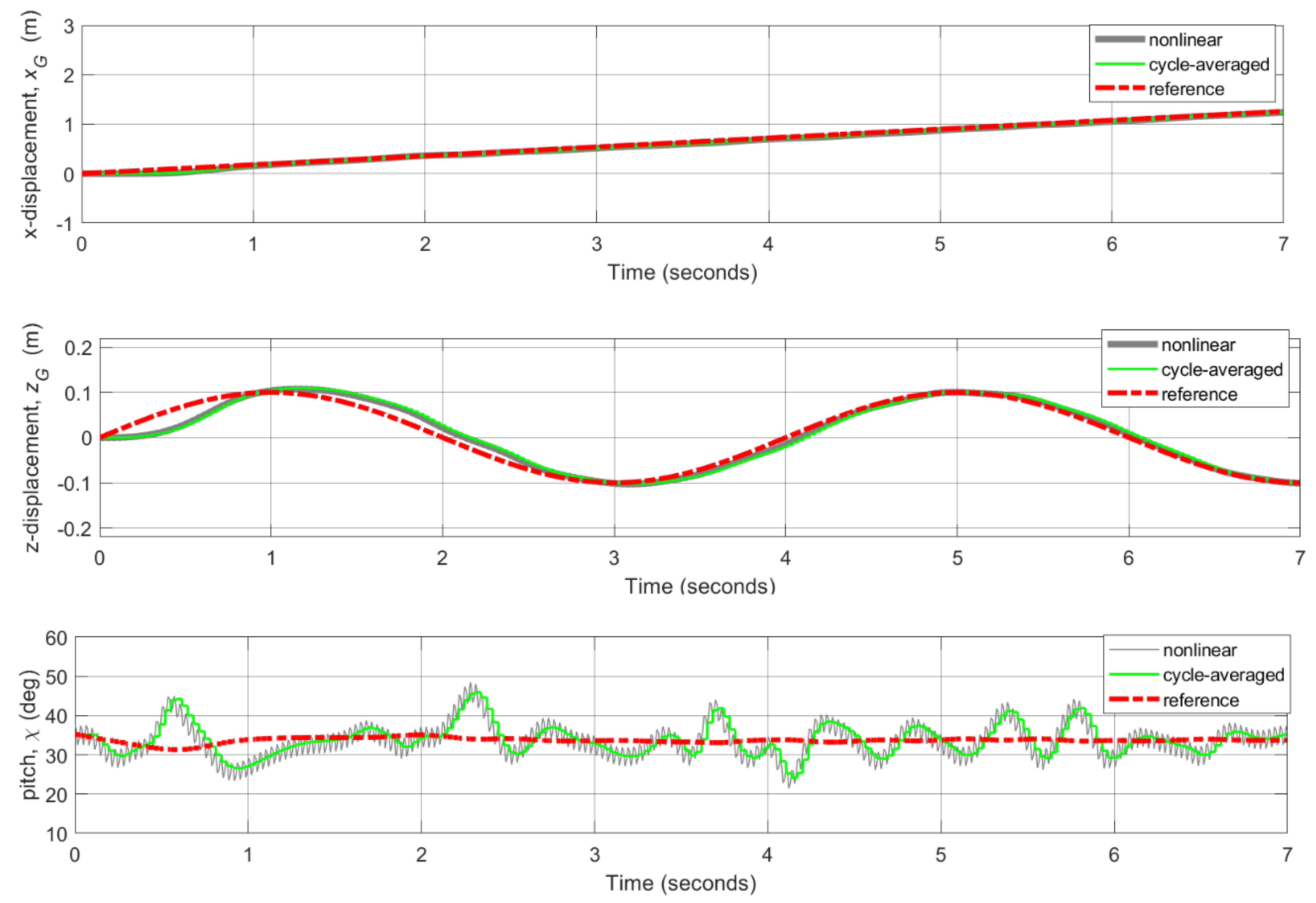
For this study, three reference trajectories with increasing level of complexity, each having x position (horizontal trajectory) and z position (vertical trajectory), were tracked to check the effectiveness of the designed controller (Section 2.6). Figure 23 shows case 1 in which the FWMAV started from rest and went to some altitude, maintaining that altitude with increasing x position. Here, both x and z reference positions were tracked very well. The reference pitch angle was also tracked well with reasonable deviation. The required control inputs for case 1 varied smoothly and were within reasonable ranges, as shown in Figure 24. Figure 25 shows case 2, in which the FWMAV started from rest and went to some altitude, maintaining that altitude and then returning to the initial altitude and retaining the initial altitude with increasing x position. In case 2, both x and z reference positions were also well tracked. The reference pitch angle was also tracked well with acceptable deviation that became slightly larger when altitude was decreased as now the body inertia and gravity played their roles. The control inputs for case 2 also varied smoothly and were within reasonable ranges, as shown in Figure 26. Results and control inputs for the most complex case 3, having sinusoidal vertical trajectory, are shown in Figure 27 and Figure 28, respectively. For all cases, it can be seen that both horizontal and vertical trajectories were efficiently tracked with reasonable ranges of control inputs.

4. Conclusions

In this study, dynamic stability analysis and flight control simulations were performed for a hawkmoth-like FWMAV model that considered the influence of time varying inertial effects of all the model’s parts. A modified quasi-steady (QS) aerodynamic model based on blade element approach that considered unsteady effects, added-mass effect, wing pitching moment effect, and rotational flow effect was utilized in this study. To find the precise trim conditions and wing kinematics at different flight speeds, we appended the multibody dynamics simulation framework with a gradient-based trim search algorithm that incorporates the aerodynamics–dynamics coupling during the convergence process for trim search calculations. The trim search results showed closed-loop trajectories of states that ensure dynamic equilibrium and help in linearization of the nonlinear model. From the eigenmode analysis, regarding longitudinal dynamics, there were stable fast and stable slow subsidence modes and an unstable oscillatory mode that became more unstable at higher speeds. The dynamic stability characterization results qualitatively conformed to the results of previous studies as discussed in Section 3.1, and results were compared between simplified and measured hawkmoth wing kinematics. The trim flight conditions, system matrices, and control matrices for various speeds were then utilized to find optimal control gains with augmented LQR control technique using gain scheduling. The designed controller worked very well to stabilize both the hovering and forward flight conditions. The gain-scheduled LQR controller was then utilized to achieve transition flight tracking that involves hovering, acceleration, constant speed, deceleration, and hovering phases for both the linear model and nonlinear multibody model. Since the designed controller worked efficiently for forward flight tracking, a dual-loop control technique, with inner velocity control loop and outer PI position control loop, was then implemented for trajectories tracking control. Three reference trajectories, each having both horizontal trajectory (x position) and vertical trajectory (z position), with increasing level of complexity were tracked successfully to validate the performance of the proposed controller. All in all, the control simulation results demonstrated that these combinations of linear control techniques worked effectively for this fairly nonlinear multibody FWMAV model. For future work, trajectory tracking optimization with minimum energy consumption for the multibody FWMAV model can be considered.

Author Contributions

Conceptualization, M.Y.B., S.-G.L. and J.-H.H.; methodology, M.Y.B. and S.-G.L.; problem formulation, M.Y.B. and J.-H.H.; software integration, M.Y.B. and S.-G.L.; formal analyses, M.Y.B.; initial results compilation M.Y.B.; resources, J.-H.H.; data curation, J.-H.H. and M.Y.B.; writing—original draft preparation, M.Y.B.; writing—review and editing, M.Y.B., S.-G.L. and J.-H.H.; visualization, M.Y.B.; final review, J.-H.H. and S.-G.L.; supervision, J.-H.H.; project administration, J.-H.H.; funding acquisition, J.-H.H. All authors have read and agreed to the published version of the manuscript.

Funding

This research was supported by Unmanned Vehicles Core Technology Research and Development Program through the National Research Foundation of Korea (NRF) and Unmanned Vehicle Advanced Research Center (UVARC) funded by the Ministry of Science and ICT, the Republic of Korea (2020M3C1C1A01083414).

Institutional Review Board Statement

Not applicable.

Informed Consent Statement

Not applicable.

Data Availability Statement

Not applicable.

Conflicts of Interest

The authors declare no conflict of interest.

References

  1. Phan, H.V.; Aurecianus, S.; Kang, T.; Park, H.C. KUBeetle-S: An insect-like, tailless, hover-capable robot that can fly with a low-torque control mechanism. Int. J. Micro Air Veh. 2019, 11, 1756829319861371. [Google Scholar] [CrossRef] [Green Version]
  2. Tijmons, S.; De Wagter, C.; Remes, B.; De Croon, G. Autonomous Door and Corridor Traversal with a 20-Gram Flapping Wing MAV by Onboard Stereo Vision. Aerospace 2018, 5, 69. [Google Scholar] [CrossRef] [Green Version]
  3. Keennon, M.; Klingebiel, K.; Won, H. Development of the nano hummingbird: A tailless flapping wing micro air vehicle. In Proceedings of the 50th AIAA Aerospace Sciences Meeting Including the New Horizons Forum and Aerospace Exposition, Nashville, TN, USA, 9–12 January 2012; p. 588. [Google Scholar]
  4. Pérez-Arancibia, N.O.; Ma, K.Y.; Galloway, K.C.; Greenberg, J.D.; Wood, R.J. First controlled vertical flight of a biologically inspired microrobot. Bioinspir. Biomim. 2011, 6, 036009. [Google Scholar] [CrossRef] [PubMed] [Green Version]
  5. Ratti, J.; Vachtsevanos, G. A biologically-inspired micro aerial vehicle. J. Intell. Robot. Syst. 2010, 60, 153–178. [Google Scholar] [CrossRef]
  6. Srigrarom, S.; Chan, W.-L. Ornithopter type flapping wings for autonomous micro air vehicles. Aerospace 2015, 2, 235–278. [Google Scholar] [CrossRef] [Green Version]
  7. Nguyen, Q.-V.; Park, H.C. Design and demonstration of a locust-like jumping mechanism for small-scale robots. J. Bionic Eng. 2012, 9, 271–281. [Google Scholar] [CrossRef]
  8. Michelson, R.; Helmick, D.; Reece, S.; Amarena, C. A reciprocating chemical muscle (RCM) for micro air vehicle ‘Entomopter’flight. Proc. Assoc. Unmanned Veh. Syst. 1997, 429–435. [Google Scholar]
  9. Orlowski, C.T.; Girard, A.R. Modeling and simulation of nonlinear dynamics of flapping wing micro air vehicles. AIAA J. 2011, 49, 969–981. [Google Scholar] [CrossRef] [Green Version]
  10. Nguyen, A.T.; Han, J.-H. Wing flexibility effects on the flight performance of an insect-like flapping-wing micro-air vehicle. Aerosp. Sci. Technol. 2018, 79, 468–481. [Google Scholar] [CrossRef]
  11. Taylor, G.K.; Thomas, A.L. Dynamic flight stability in the desert locust Schistocerca gregaria. J. Exp. Biol. 2003, 206, 2803–2829. [Google Scholar] [CrossRef] [Green Version]
  12. Taylor, G.K.; Żbikowski, R. Nonlinear time-periodic models of the longitudinal flight dynamics of desert locusts Schistocerca gregaria. J. R. Soc. Interface 2005, 2, 197–221. [Google Scholar] [CrossRef] [Green Version]
  13. Nguyen, A.T. Effects of Body Aerodynamics and Wing Flexibility on Flight Characteristics of Insect-Like Flapping-Wing Micro Air Vehicles. Ph.D. Dissertation, Korea Advanced Institute of Science and Technology, Daejeon, Korea, 2017. [Google Scholar]
  14. Kalliny, A.N.; El-Badawy, A.A.; Elkhamisy, S.M. Command-filtered integral backstepping control of longitudinal flapping-wing flight. J. Guid. Control Dyn. 2018, 41, 1556–1568. [Google Scholar] [CrossRef]
  15. Kim, J.-K.; Han, J.-H. A multibody approach for 6-DOF flight dynamics and stability analysis of the hawkmoth Manduca sexta. Bioinspir. Biomim. 2014, 9, 016011. [Google Scholar] [CrossRef] [Green Version]
  16. Taha, H.E.; Hajj, M.R.; Nayfeh, A.H. Flight dynamics and control of flapping-wing MAVs: A review. Nonlinear Dyn. 2012, 70, 907–939. [Google Scholar] [CrossRef]
  17. Taylor, G.; Thomas, A. Animal flight dynamics II. Longitudinal stability in flapping flight. J. Theor. Biol. 2002, 214, 351–370. [Google Scholar] [CrossRef]
  18. Taylor, G.; Bomphrey, R.; ‘t Hoen, J. Insect flight dynamics and control. In Proceedings of the 44th AIAA Aerospace Sciences Meeting and Exhibit, Reno, NV, USA, 9–12 January 2006; p. 32. [Google Scholar]
  19. Sun, M.; Wang, J.; Xiong, Y. Dynamic flight stability of hovering insects. Acta Mech. Sin. 2007, 23, 231–246. [Google Scholar] [CrossRef]
  20. Dietl, J.M.; Garcia, E. Stability in ornithopter longitudinal flight dynamics. J. Guid. Control Dyn. 2008, 31, 1157–1163. [Google Scholar] [CrossRef]
  21. Doman, D.; Oppenheimer, M.; Sigthorsson, D. Dynamics and control of a minimally actuated biomimetic vehicle: Part i-aerodynamic model. In Proceedings of the AIAA Guidance, Navigation, and Control Conference, Chicago, IL, USA, 10–13 August 2009; p. 6160. [Google Scholar]
  22. Oppenheimer, M.; Doman, D.; Sigthorsson, D. Dynamics and control of a minimally actuated biomimetic vehicle: Part ii-control. In Proceedings of the AIAA Guidance, Navigation, and Control Conference, Chicago, IL, USA, 10–13 August 2009; p. 6161. [Google Scholar]
  23. Hedrick, T.L.; Cheng, B.; Deng, X. Wingbeat time and the scaling of passive rotational damping in flapping flight. Science 2009, 324, 252–255. [Google Scholar] [CrossRef] [Green Version]
  24. Faruque, I.; Humbert, J.S. Dipteran insect flight dynamics. Part 1 Longitudinal motion about hover. J. Theor. Biol. 2010, 264, 538–552. [Google Scholar] [CrossRef]
  25. Sun, M.; Xiong, Y. Dynamic flight stability of a hovering bumblebee. J. Exp. Biol. 2005, 208, 447–459. [Google Scholar] [CrossRef] [Green Version]
  26. Orlowski, C.; Girard, A.; Shyy, W. Derivation and simulation of the nonlinear dynamics of a flapping wing micro-air vehicle. In Proceedings of the European Micro-Air Vehicle Conference and Competition, Delft, The Netherlands, 14–17 September 2009. [Google Scholar]
  27. Su, W.; Cesnik, C. Flight dynamic stability of a flapping wing micro air vehicle in hover. In Proceedings of the 52nd AIAA/ASME/ASCE/AHS/ASC Structures, Structural Dynamics and Materials Conference, Denver, CO, USA, 4–7 April 2011; p. 2009. [Google Scholar]
  28. Bolender, M. Rigid multi-body equations-of-motion for flapping wing mavs using kane’s equations. In Proceedings of the AIAA Guidance, Navigation, and Control Conference, Chicago, IL, USA, 10–13 August 2009; p. 6158. [Google Scholar]
  29. Gebert, G.; Gallmeier, P.; Evers, J. Equations of motion for flapping flight. In Proceedings of the AIAA Atmospheric Flight Mechanics Conference and Exhibit, Monterey, CA, USA, 5–8 August 2002; p. 4872. [Google Scholar]
  30. Grauer, J.A.; Hubbard Jr, J.E. Multibody model of an ornithopter. J. Guid. Control Dyn. 2009, 32, 1675–1679. [Google Scholar] [CrossRef]
  31. Xiong, Y.; Sun, M. Dynamic flight stability of a bumblebee in forward flight. Acta Mech. Sin. 2008, 24, 25–36. [Google Scholar] [CrossRef]
  32. Wu, J.H.; Sun, M. Floquet stability analysis of the longitudinal dynamics of two hovering model insects. J. R. Soc. Interface 2012, 9, 2033–2046. [Google Scholar] [CrossRef] [Green Version]
  33. Strogatz, S.H. Nonlinear Dynamics and Chaos: With Applications to Physics, Biology, Chemistry and Engineering; Westview Press: Boulder, CO, USA, 1994. [Google Scholar]
  34. Gao, N.; Aono, H.; Liu, H. Perturbation analysis of 6DoF flight dynamics and passive dynamic stability of hovering fruit fly Drosophila melanogaster. J. Theor. Biol. 2011, 270, 98–111. [Google Scholar] [CrossRef] [PubMed]
  35. Gao, N.; Aono, H.; Liu, H. A numerical analysis of dynamic flight stability of hawkmoth hovering. J. Biomech. Sci. Eng. 2009, 4, 105–116. [Google Scholar] [CrossRef] [Green Version]
  36. Pennycuick, C.J. Power requirements for horizontal flight in the pigeon Columba livia. J. Exp. Biol. 1968, 49, 527–555. [Google Scholar] [CrossRef]
  37. Ellington, C.P. The aerodynamics of hovering insect flight. V. A vortex theory. Philos. Trans. R. Soc. London B Biol. Sci. 1984, 305, 115–144. [Google Scholar]
  38. Phlips, P.; East, R.; Pratt, N. An unsteady lifting line theory of flapping wings with application to the forward flight of birds. J. Fluid Mech. 1981, 112, 97–125. [Google Scholar] [CrossRef]
  39. Ansari, S.A. A Nonlinear, Unsteady Aerodynamic Model for Insect-Like Flapping Wings in the Hover with Micro Air Vehicle Applications. Ph.D. Dissertation, Cranfield University, Bedford, UK, 2004. [Google Scholar]
  40. Xuan, H.; Hu, J.; Yu, Y.; Zhang, J. Recent progress in aerodynamic modeling methods for flapping flight. AIP Adv. 2020, 10, 020701. [Google Scholar] [CrossRef]
  41. Sane, S.P.; Dickinson, M.H. The aerodynamic effects of wing rotation and a revised quasi-steady model of flapping flight. J. Exp. Biol. 2002, 205, 1087–1096. [Google Scholar] [CrossRef]
  42. Han, J.-S.; Kim, J.-K.; Chang, J.W.; Han, J.-H. An improved quasi-steady aerodynamic model for insect wings that considers movement of the center of pressure. Bioinspir. Biomim. 2015, 10, 046014. [Google Scholar] [CrossRef]
  43. Taha, H.E.; Hajj, M.R.; Nayfeh, A.H. Longitudinal flight dynamics of hovering MAVs/insects. J. Guid. Control Dyn. 2014, 37, 970–979. [Google Scholar] [CrossRef]
  44. Au, L.T.K.; Park, H.C. Influence of center of gravity location on flight dynamic stability in a hovering tailless FW-MAV: Longitudinal motion. J. Bionic Eng. 2019, 16, 130–144. [Google Scholar] [CrossRef]
  45. Kim, J.-K.; Han, J.-S.; Lee, J.-S.; Han, J.-H. Hovering and forward flight of the hawkmoth Manduca sexta: Trim search and 6-DOF dynamic stability characterization. Bioinspir. Biomim. 2015, 10, 056012. [Google Scholar] [CrossRef] [PubMed]
  46. Cheng, B.; Deng, X. Translational and rotational damping of flapping flight and its dynamics and stability at hovering. IEEE Trans. Robot. 2011, 27, 849–864. [Google Scholar] [CrossRef]
  47. Oppenheimer, M.W.; Doman, D.B.; Sigthorsson, D.O. Dynamics and control of a biomimetic vehicle using biased wingbeat forcing functions. J. Guid. Control Dyn. 2011, 34, 204–217. [Google Scholar] [CrossRef]
  48. Loh, K.; Cook, M.; Thomasson, P. An investigation into the longitudinal dynamics and control of a flapping wing micro air vehicle at hovering flight. Aeronaut. J. 2003, 107, 743–753. [Google Scholar]
  49. Khanmirza, E.; Yousefi-Koma, A.; Tarvirdizadeh, B. Nonlinear trajectory control of a flapping-wing micro aerial vehicle. Aircr. Eng. Aerosp. Technol. 2012, 84, 58–65. [Google Scholar] [CrossRef]
  50. Banazadeh, A.; Taymourtash, N. Adaptive attitude and position control of an insect-like flapping wing air vehicle. Nonlinear Dyn. 2016, 85, 47–66. [Google Scholar] [CrossRef]
  51. Wissa, B.E.; Elshafei, K.O.; El-Badawy, A.A. Lyapunov-based control and trajectory tracking of a 6-DOF flapping wing micro aerial vehicle. Nonlinear Dyn. 2020, 99, 2919–2938. [Google Scholar] [CrossRef]
  52. Khosravi, M.; Novinzadeh, A. A multi-body control approach for flapping wing micro aerial vehicles. Aerosp. Sci. Technol. 2021, 112, 106525. [Google Scholar] [CrossRef]
  53. Guo, S.; Li, H.; Zhou, C.; Zhang, Y.L.; He, Y.; Wu, J.H. Analysis and experiment of a bio-inspired flyable micro flapping wing rotor. Aerosp. Sci. Technol. 2018, 79, 506–517. [Google Scholar] [CrossRef] [Green Version]
  54. Wu, J.H.; Zhang, Y.L.; Sun, M. Hovering of model insects: Simulation by coupling equations of motion with Navier–Stokes equations. J. Exp. Biol. 2009, 212, 3313–3329. [Google Scholar] [CrossRef] [Green Version]
  55. Serrani, A.; Keller, B.; Bolender, M.; Doman, D. Robust control of a 3-dof flapping wing micro air vehicle. In Proceedings of the AIAA Guidance, Navigation, and Control Conference, Toronto, ON, Canada, 2–5 August 2010; p. 7709. [Google Scholar]
  56. Schenato, L.; Campolo, D.; Sastry, S. Controllability issues in flapping flight for biomimetic micro aerial vehicles (MAVs). In Proceedings of the 42nd IEEE International Conference on Decision and Control (IEEE Cat. No. 03CH37475), Maui, HI, USA, 9–12 December 2003; pp. 6441–6447. [Google Scholar]
  57. Peng, K.; Lin, F.; Chen, B.M. Modeling and control analysis of a flapping-wing micro aerial vehicle. In Proceedings of the 2017 13th IEEE International Conference on Control & Automation (ICCA), Ohrid, Macedonia, 3–6 July 2017; pp. 295–300. [Google Scholar]
  58. Zhu, B.; Zuo, Z. Adaptive model predictive control for set-point tracking of a single-DOF flapping-wing unmanned aerial vehicle. In Proceedings of the 2017 13th IEEE International Conference on Control & Automation (ICCA), Ohrid, Macedonia, 3–6 July 2017; pp. 861–866. [Google Scholar]
  59. Ellington, C.P. The Aerodynamics of Hovering Insect Flight. II. Morphological Parameters. Philos. Trans. R. Soc. B 1984, 305, 17–40. [Google Scholar]
  60. Hedrick, T.L.; Daniel, T.L. Flight control in the hawkmoth Manduca sexta: The inverse problem of hovering. J. Exp. Biol. 2006, 209, 3114–3130. [Google Scholar] [CrossRef] [Green Version]
  61. O’Hara, R.P.; Palazotto, A.N. The morphological characterization of the forewing of the Manduca sexta species for the application of biomimetic flapping wing micro air vehicles. Bioinspir. Biomim. 2012, 7, 046011. [Google Scholar] [CrossRef]
  62. Willmott, A.P.; Ellington, C.P. The mechanics of flight in the hawkmoth Manduca sexta. I. Kinematics of hovering and forward flight. J. Exp. Biol. 1997, 200, 2705–2722. [Google Scholar] [CrossRef]
  63. Berman, G.J.; Wang, Z.J. Energy-minimizing kinematics in hovering insect flight. J. Fluid Mech. 2007, 582, 153–168. [Google Scholar] [CrossRef] [Green Version]
  64. Faruque, I.; Humbert, J.S. Dipteran insect flight dynamics. Part 2: Lateral–directional motion about hover. J. Theor. Biol. 2010, 265, 306–313. [Google Scholar] [CrossRef] [PubMed]
  65. Pfeiffer, A.T.; Lee, J.-S.; Han, J.-H.; Baier, H. Ornithopter Flight Simulation Based on Flexible Multi-Body Dynamics. J. Bionic Eng. 2010, 7, 102–111. [Google Scholar] [CrossRef]
  66. Lee, J.-S.; Kim, J.-K.; Kim, D.-K.; Han, J.-H. Longitudinal Flight Dynamics of Bioinspired Ornithopter Considering Fluid-Structure Interaction. J. Guid. Control Dyn. 2011, 34, 667–677. [Google Scholar] [CrossRef]
  67. Gear, C. Simultaneous Numerical Solution of Differential-Algebraic Equations. IEEE Trans. Circuit Theory 1971, 18, 89–95. [Google Scholar] [CrossRef]
  68. Nelson, R.C. Flight Stability and Automatic Control; WCB/McGraw Hill: New York, NY, USA, 1998. [Google Scholar]
  69. Skogestad, S.; Postlethwaite, I. Multivariable Feedback Control: Analysis and Design; Wiley: New York, NY, USA, 2007. [Google Scholar]
  70. Kwakernaak, H.; Sivan, R. Linear Optimal Control Systems; Wiley-Interscience: New York, NY, USA, 1972. [Google Scholar]
  71. Willmott, A.P.; Ellington, C.P. The mechanics of flight in the hawkmoth Manduca sexta. II. Aerodynamic consequences of kinematic and morphological variation. J. Exp. Biol. 1997, 200, 2723–2745. [Google Scholar] [CrossRef] [PubMed]
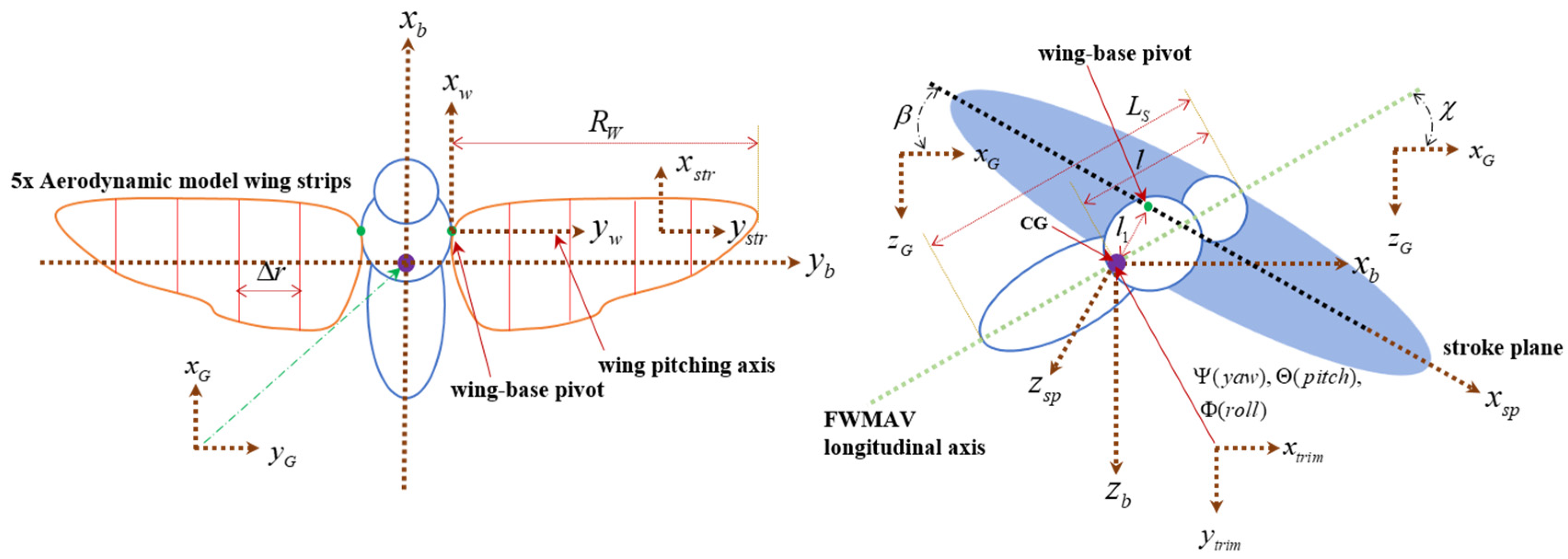
Figure 1. FWMAV multibody model and coordinate systems.
Aerospace 08 00362 g001
Figure 2. (a) Wing kinematics definition; (b) comparison between hawkmoth’s measurements from Willmott and Ellington [62] and simplified wing kinematics.
Aerospace 08 00362 g002
Figure 3. Multibody dynamics simulation framework for FWMAV model.
Aerospace 08 00362 g003
Figure 4. Gradient-based trim search algorithm.
Aerospace 08 00362 g004
Figure 5. Schematic diagram of gain-scheduled LQR control loop for transition flight tracking of the linear model.
Aerospace 08 00362 g005
Figure 6. Gain matrix values for KS at different flight speeds.
Aerospace 08 00362 g006
Figure 7. Gain matrix values for KI at different flight speeds.
Aerospace 08 00362 g007
Figure 8. Multibody dynamics simulation framework appended with flight control block.
Aerospace 08 00362 g008
Figure 9. Schematic diagram of gain-scheduled LQR controller design for maintaining fixed flight conditions (stabilizing hovering and forward flight states).
Aerospace 08 00362 g009
Figure 10. Schematic diagram of gain-scheduled LQR controller design for transition flight tracking of the nonlinear multibody model.
Aerospace 08 00362 g010
Figure 11. Discontinuity (left) in cycle averaged/mean inputs (frequency and wing kinematics) and modification (right) for its solution in nonlinear FWMAV control.
Aerospace 08 00362 g011
Figure 12. Schematic diagram of dual loop position control for reference trajectories tracking for the nonlinear multibody model.
Aerospace 08 00362 g012
Figure 13. Trimmed flight trajectories in hovering and forward flight: the cross and square symbols indicate the initial and final points, respectively.
Aerospace 08 00362 g013
Figure 14. Nondimensionalized longitudinal dynamics stability derivatives for simplified wing kinematics.
Aerospace 08 00362 g014
Figure 15. Nondimensionalized longitudinal dynamics eigenvalues at various flight speeds (hovering and forward flight).
Aerospace 08 00362 g015
Figure 16. Flight control simulations for hovering flight control.
Aerospace 08 00362 g016
Figure 17. Flight control simulations for forward flight control (flight speed = 0.5 m/s).
Aerospace 08 00362 g017aAerospace 08 00362 g017b
Figure 18. Flight control simulations for forward flight control (flight speed = 1 m/s).
Aerospace 08 00362 g018
Figure 19. Flight control simulations for transition flight control of linear FWMAV model.
Aerospace 08 00362 g019
Figure 20. Flight control inputs for transition flight control of linear FWMAV model.
Aerospace 08 00362 g020aAerospace 08 00362 g020b
Figure 21. Flight control simulations for transition flight control of nonlinear FWMAV model.
Aerospace 08 00362 g021
Figure 22. Flight control inputs for transition flight control of nonlinear FWMAV model.
Aerospace 08 00362 g022
Figure 23. Flight control simulations for trajectories tracking control of nonlinear FWMAV model (case 1).
Aerospace 08 00362 g023
Figure 24. Flight control inputs for trajectories tracking control of nonlinear FWMAV model (case 1).
Aerospace 08 00362 g024
Figure 25. Flight control simulations for trajectories tracking control of nonlinear FWMAV model (case 2).
Aerospace 08 00362 g025
Figure 26. Flight control inputs for trajectories tracking control of nonlinear FWMAV model (case 2).
Aerospace 08 00362 g026
Figure 27. Flight control simulations for trajectories tracking control of nonlinear FWMAV model (case 3).
Aerospace 08 00362 g027
Figure 28. Flight control inputs for trajectories tracking control of nonlinear FWMAV model (case 3).
Aerospace 08 00362 g028
Table 1. Morphological parameters and nomenclature of the reference hawkmoth-like FWMAV.
Parameter (Unit)DescriptionValue
ms (mg)Total system’s mass1437.5
mw (mg)Single wing’s mass48.3
Ls (mm)Total length of the system (anterior tip to posterior tip)40.2
Rw (mm)Wing span48.3
r2 (mm)Radius of second moment of wing area24.6
tw (mm)Wing thickness3.7 × 10−2
Sw (mm2)Single wing area879.8
c ¯ (mm)Mean aerodynamic chord18.1
l1 (mm)Distance between center of mass (CG) and wing-pivot point10.9
l (mm)Distance between center of mass (CG) and anterior tip20.5
Iyy (kg·mm2)Mass moment of inertia of the system0.28
χo (o)Trimmed body pitch angleTrimmed result
βo (o)Trimmed stroke plane angleTrimmed result
fo (Hz)Trimmed flapping frequencyTrimmed result
ϕo (o)Trimmed stroke positional angleTrimmed result
αo (o)Trimmed feathering angleTrimmed result
f (Hz)Flapping frequencyWing kinematics
ϕ (o)Stroke positional angleWing kinematics
α (o)Feathering angleWing kinematics
Table 2. Trimmed flight conditions from trim search algorithm for controller design.
Flight Speed (m/s)fo (Hz)ϕo (deg)αo (deg)χo (deg)βo (deg)
030.6879.01398.74937.50619.496
0.2530.54610.52097.56335.40921.593
0.530.41212.10796.53833.28323.719
0.7530.14113.61395.86731.20325.796
129.97615.17895.329.11227.889
Publisher’s Note: MDPI stays neutral with regard to jurisdictional claims in published maps and institutional affiliations.