Article

Aerodynamic Performance of a Nanostructure-Induced Multistable Shell

1
Center for Advanced Structural Materials, City University of Hong Kong Shenzhen Research Institute, Greater Bay Joint Division, Shenyang National Laboratory for Materials Science, Shenzhen 518057, China
2
Center for Turbulence Control, Harbin Institute of Technology (Shenzhen), Shenzhen 518055, China
3
Department of Aeronautical and Aviation Engineering, The Hong Kong Polytechnic University, Hong Kong, China
4
Department of Architecture and Civil Engineering, City University of Hong Kong, Hong Kong, China
5
Department of Mechanical Engineering, City University of Hong Kong, Hong Kong, China
6
City University of Hong Kong Shenzhen Futian Research Institute, Shenzhen 518045, China
*
Authors to whom correspondence should be addressed.
Yi, S. and Shen, L. contribute equally in this work.
Aerospace 2021, 8(11), 350; https://doi.org/10.3390/aerospace8110350
Submission received: 13 September 2021 / Revised: 26 October 2021 / Accepted: 28 October 2021 / Published: 18 November 2021
(This article belongs to the Special Issue Bioinspired Flying Systems)

Abstract

:
Multistable shells that have the ability to hold more than one stable configuration are promising for adaptive structures, especially for airfoil. In contrast to existing studies on bistable shells, which are well demonstrated by the Venus flytrap plant with the ability to feed itself, this work experimentally studies the aerodynamic response of various stable configurations of a nanostructure-induced multistable shell. This multistable shell is manufactured by using nanotechnology and surface mechanical attrition treatment (SMAT) to locally process nine circular zones in an original flat plate. The aerodynamic responses of eight stable configurations of the developed multistable shell, including four twisted configurations and four untwisted configurations with different cambers, are visually captured and quantitively measured in a wind tunnel. The results clearly demonstrate the feasibility of utilizing different controllable configurations to adjust the aerodynamic performance of the multistable shell.

1. Introduction

Morphing structures are very promising in engineering fields, especially in the aerodynamic domain, to provide multiple configurations and realize various functions using one structure. Traditionally, shape adaptation is obtained through complex mechanical systems [1], which are potentially replaced by small, reliable and lightweight systems made from smart materials. In addition, morphing structures taking advantage of advanced materials [2,3] or new conceptual designs [4] are extensively proposed for use in aircrafts [5] with the consideration of low mass, large shape adaptability and high load carrying capacity of the structures. Owing to the promising application of morphing structures, multistable shells are proposed via various manufacturing methods [6,7,8], especially for bistable laminated composite shells [9,10].
With the ability of holding more than one stable configuration by their own mechanical properties, multistable shells provide an ideal solution for morphing structures without requiring external supports or consuming input energies continuously, which are demonstrated by the Venus flytrap plant that has the ability to feed itself in nature [11]. The shape adaptation can be realized by using smart material with a finite energy [12,13,14,15,16,17], which transforms a synthetic multistable shell from one stable configuration into another stable one, providing a significant advantage over morphing structures that rely on inputting energies continuously to maintain deformations. Bistable shells were proposed as bistable winglets and flaps for morphing wings [18,19]. The experimental results indicated that the morphing wing built with bistable shells had considerably different aerodynamic responses in two different stable states. However, no report has been found on aerodynamic behaviors of multistable shells that could hold more than two stable configurations.
For existing tristable shells, the specific three stable configurations in doubly curved shapes are difficult to apply to aircraft surfaces [7,20]. For the multistable structures assembled by several bistable shells via joints [21], the discontinuous surfaces impeded their aerodynamic applications. On the other hand, by tessellating bistable shells using biasing strips along one direction provides the continuous surface with multiple stable configurations [22]. However, the attempt to have bistable shells tessellated in plane in two directions has failed [23]. Aerodynamic multistable shells cannot be achieved via this approach. It is noticed that multistable shells formed by dimpling on ultrathin metallic sheets can have various configurations [6]. Nevertheless, this method is only applicable to ultrathin sheets (~0.1 mm thickness) and the stabilities of the multistable ultrathin shells obstruct their applications.
In this work, we report one multistable shell, which was manufactured from metallic plates using the nanotechnique of surface mechanical attrition treatment (SMAT). Its aerodynamic behavior in various stable configurations is studied for potential applications as flaps or adaptive wing skins for aircraft.

2. Materials and Methods

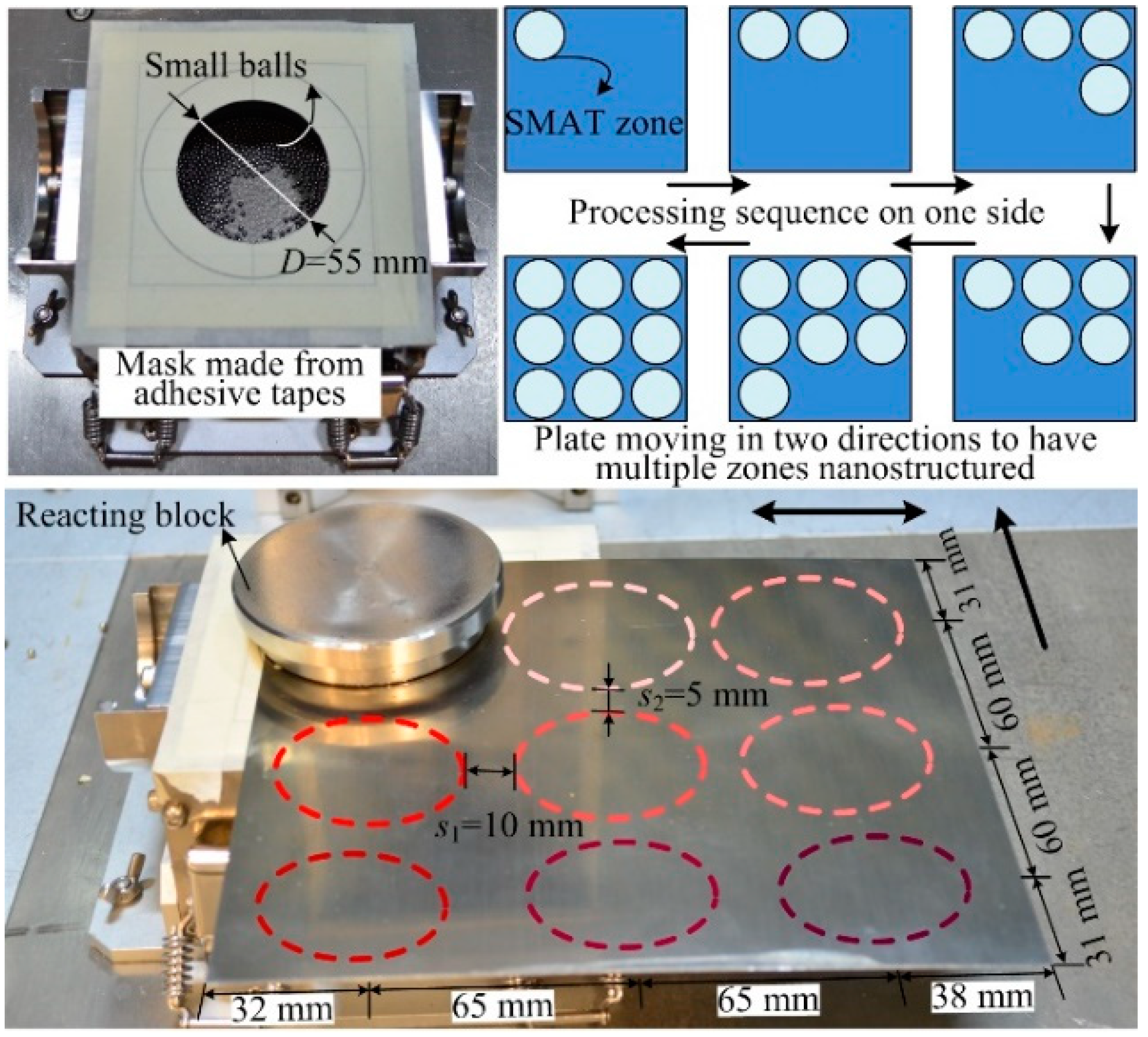
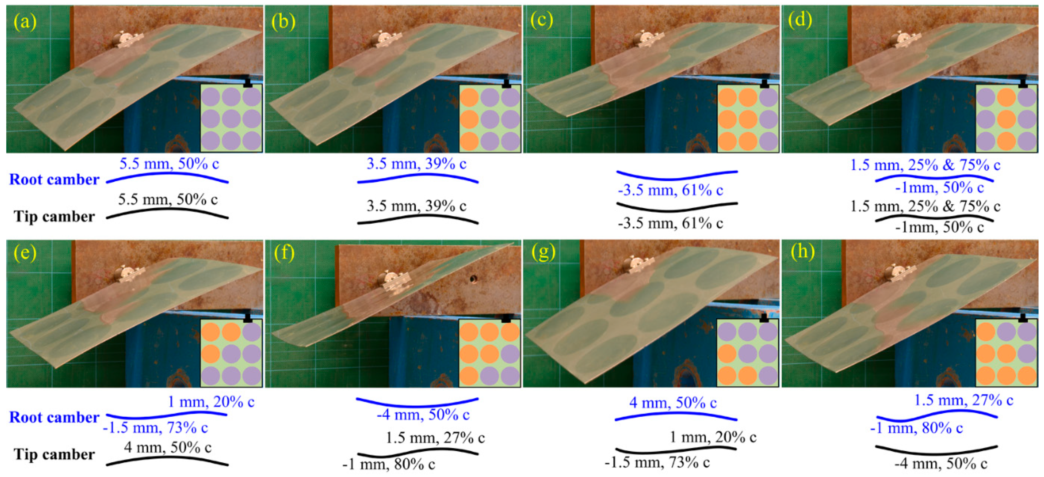
2.1. Manufacture of the Multistable Shell

Not limited to materials, an original flat commercial SUS304 stainless steel plate with a thickness of 0.46 mm is directly cut into a dimension of 182 × 200 mm2. Nine circular zones in a regular matrix form were selected to be processed with the SMAT process on both sides using turns. A total of 304 stainless steel balls, with a diameter of 2 mm and total mass of 25 g, were used to randomly impact on the plate at fast speeds during the SMAT process. A 3.3 kW power generator was used for a 20 kHz ultrasonic transducer to accelerate the balls in a confined chamber that had a height of 35 mm. The detailed setup can be found in references [24,25,26]. The treatment in multiple local zones was realized by using one SMAT chamber and moving the plate horizontally in two directions, as shown in Figure 1. As the inner diameter of the chamber was larger than the diameter of the circular treated zone, a mask made from adhesive tapes was used. The nine circular zones were processed with the SMAT process on one side by the sequence shown in Figure 1. Each circular zone was processed for 8 s in one treatment. The plate was then processed on the other side following the same procedure. After several iterative treatments the processed zones became able to hold a local bistability [27], and the monostable flat plate became a multistable shell with multiple nanostructured zones capping up or down. In this study, each circular zone was processed with the SMAT process for 544 s in total.
During the SMAT process, the fast moving balls randomly impacted the plate’s surface to transfer energies obtained from the ultrasonic transducer into the processed material. Gradient plastic deformations induced from severe impacts accumulated within the processed zone, stretching the plate under the constraint of the untreated region. Compressive stresses were induced in the treated zone. When the compressive stresses coming from the accumulated plastic deformations were large enough, the treated zone was transversely buckled and able to cap in two sides and hold a local bistability. With the further SMAT processes, the two stable capping states of the nanostructured zone became more obvious and were stable enough to hold external forces. At the same time, every processed zone interplayed with nearby treated zones, which enabled the shell to hold multiple states in complex configurations, as shown in Figure 2. As the yield strength of the material in the nanostructured region was largely improved by the induced nanostructures, the elastic deformation of the nanostructured shell was much increased and the transition of the nanostructured zone capping up and down did not involve plastic deformations. It is worth emphasizing that this physical nanotechnique is workable for various metallic materials with plastic properties, including aluminum, magnesium and titanium alloys, to develop multistable shells in designable configurations by selecting the nanostructured regions.
Notably, there exists 2n stable configurations of the developed multistable shells with n nanostructured zones because each separated nanostructured zone can cap in two sides. The residual stresses in the shells control the stable configurations, which are determined by the nanostructuring process, the dimension and the shape of nanostructured regions and their distribution. As mentioned above, in this study, a simple multistable shell with nine circular nanostructured zones in a regular matrix form was selected as the case to demonstrate adaptive aerodynamic behavior of multistable shells. Based on the study of ultrathin metallic multistable shells using dimpling, a uniformly dimpled sheet curved along the direction normal to the least packing of caps [6] when the deformed caps were simultaneously open to the same side, resulting in the minimum bending stiffness and the maximum curving effect by dimpling-induced residual stresses. This property only works for nanostructure-induced multistable shells with circular nanostructured zones when they are uniformly distributed with the least-packing direction perpendicular to the most-packing direction. The conducted numerical model and experimental results showed that the multistable shell with uniformly distributed circular nanostructured regions, which are simultaneously open to the same side, curved along the direction with the most packing of the processed regions (see Figure 2a), whose stable configurations had a weak relationship with the least-packing direction. Such cylindrical configurations enabled the processed shells to more effectively release the internal in-plane stresses left by the nanocrystallization process. Here the nine nanostructured zones were arranged in a regular matrix form but with different spacings between two adjacent nanostructured zones in the streamwise and spanwise directions. This was in order to make the multistable shell curve along the short side (182 mm in length) when all the nanostructured zones were capping toward one side, as shown in Figure 2a. Notably, the diameter of the hole in the mask was 55 mm while the diameter of the nanostructured circular regions was 54 mm, owing to the boundary gap induced by the mask. This resulted in the change of distances s1 and s2 between two adjacent circular zones from the designed 5 mm and 10 mm to the actual 6 mm and 11 mm along the short side and the long side, respectively.

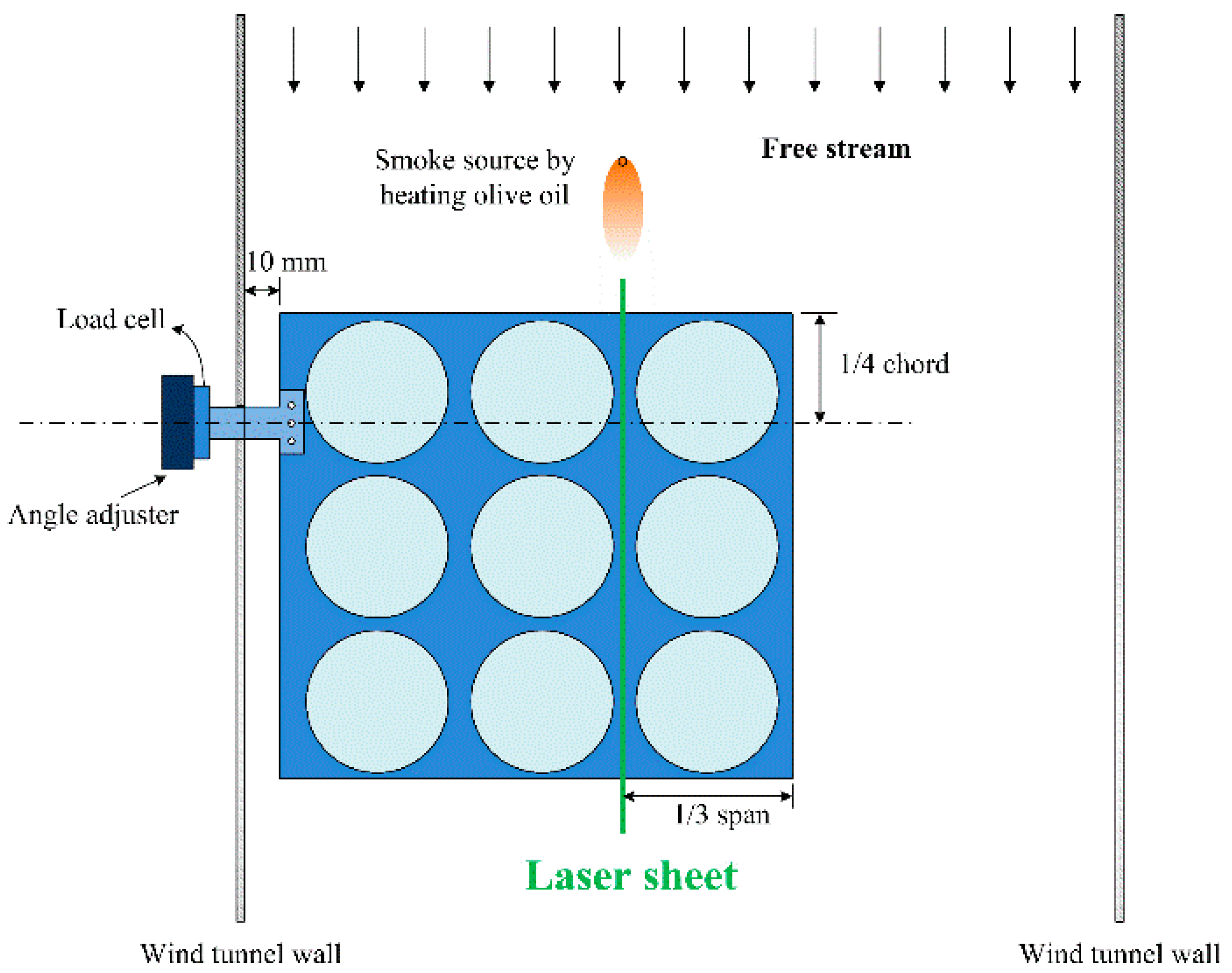
2.2. Aerodynamic Experiment Setup

As shown in the pictures of Figure 2, eight stable configurations of the nanostructure induced multistable shell, mimicking a cantilevered wing surface, were tested for their aerodynamic performance in a wind tunnel. The manufactured multistable shell was clipped at one short side as a free thin wing and the long side of the shell was along the wing span. The wing root cambers and wing tip cambers of the eight configurations were projected onto white papers and measured by a micrometer. These configurations were schematized in Figure 2 and not affected by the clipper. As seen, symmetric configurations (to the central row), (a)–(d), yield very similar root camber and tip camber profiles, whereas, the asymmetric configurations, (e)–(h), result in different root camber and tip camber profiles and consequently the twist of the morphing surface. Here, two angles of attack were introduced in this study: one is the body angle of attack, αb, defined as the angle between the central lines of the wind tunnel and the clamp inclination; the other one is the root angle of attack, αr, defined as the angle between the central line of the wind tunnel and the root chord.
The wind tunnel experiment was conducted in a closed-loop, low-speed facility with a turbulence intensity of less than 0.5%. The dimensions of the test section were 60 cm (width) × 60 cm (height) × 220 cm (length). The wind tunnel experiment setup is shown in Figure 3. The laser sheet was set at 1/3 of the span to the wing tip, generated by a continuous laser (APGL-FN-532-1W). A 0.5 mm hot wire was used to heat the olive oil to generate smoke. The flow evolutions were recorded with a digital camera (SONY α560). The force data were measured by a three-axis load cell (Kyowa LSM-B-50NSA1), which was fixed on an angle adjuster. The central line of the load cell was at the position of ¼ of the chord length. The sampling frequency of force data collection was 2000 Hz. The force data were collected for 30 s during every measurement. Three measurements were conducted for each case to ensure the repeatability. The measurement uncertainty of forces was around 0.5%. The experiment was conducted at a freestream of 7.4 m/s, with a Reynolds number of 100,000 based on the chord length. No fluttering was observed in all experiments.

3. Results and Discussions

3.1. Flow Visualization in Various Stable Configurations

The smoke flow visualization results of the tested multistable shell in eight configurations are shown and schematized in Figure 4. During this experiment, the clamp angle of the connector (from the load cell to the shell) was fixed and only the configuration of the shell changed, resulting in a constant body angle of attack (αb = 20 degree) and a changing root angle of attack (αr). The purpose of this setup is to investigate the change of the flow structure caused by the morphing surface using different configurations in a stationary flow. The boundary of the separated flow for each configuration was highlighted with the white solid line in Figure 4. In some cases (for example, Figure 4a,b), the flow reattached to the upper surface in downstream, forming a recirculation bubble (known as the leading edge separation bubble [28,29]). In other cases (for example, Figure 4c,f), no reattachment happened on the upper surface. As a result, the flow over the morphing surface became turbulent and vortex shedding can be observed. A comparison of these cases that is shown in Figure 4 indicates that cases (a), (b), (d), (e) and (g) are approaching stall while the other cases are under post-stall conditions. Further comparison of the separation bubble size among those cases before stall shows they are approaching stall at different extents. The variations of the flow structure are mainly attributed to the different incident camber angles and effective angles of attack by shape morphing. The three-dimensional surface caused by the control nanostructured zones may also have affected the flow structures. In summary, in the case of a fixed body angle of attack, αb, the morphing surface has the feasibility to change its configuration (root and tip cambers) and effective angle of attack simultaneously, leading to an advance or a delay of the stall.

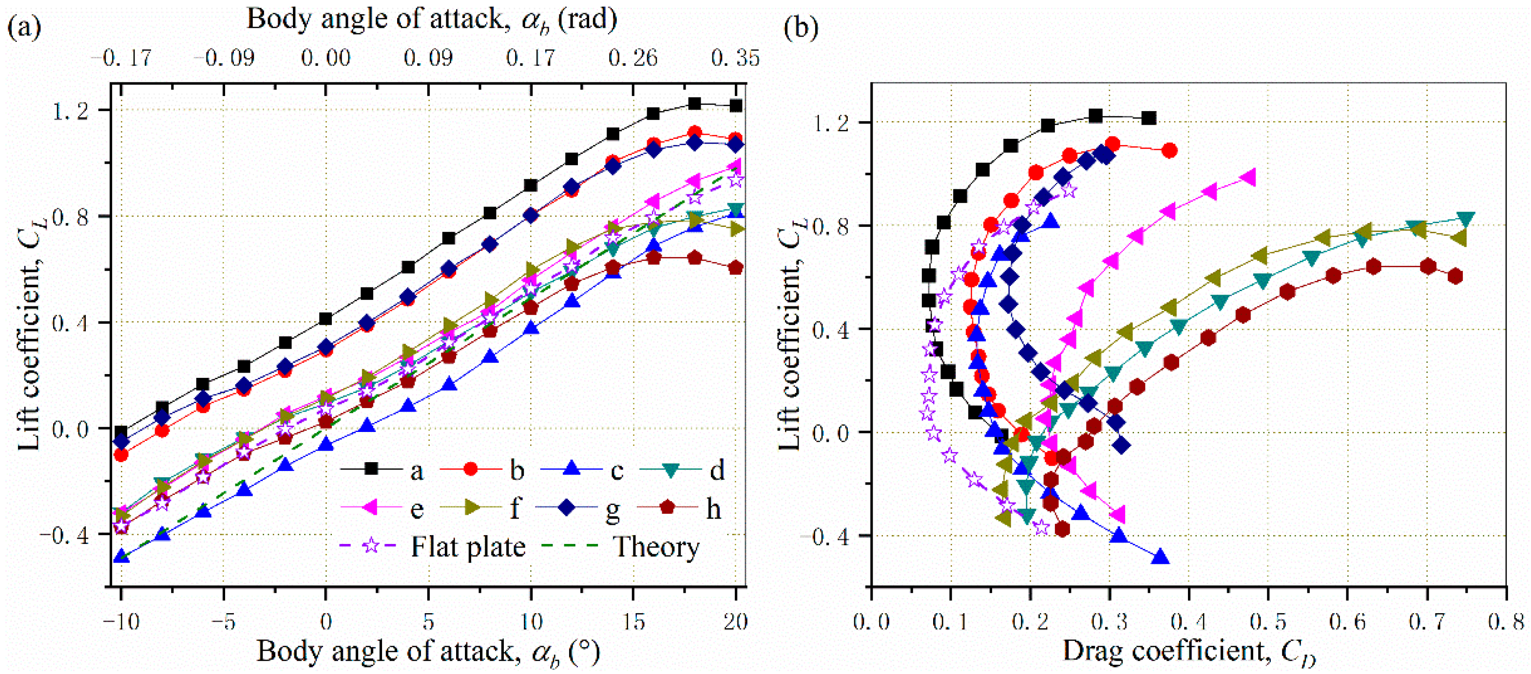
3.2. Lift and Drag Coefficients

The lift coefficient CL data of the tested shell (nine cases corresponding to eight cambered cases, as shown in Figure 2, and a flat plate case) versus the body angle of attack are shown in Figure 5a. Here, the lift coefficient is defined as
CL = L/(0.5ρSv2),
where L and S are the measured lift force and surface area, respectively. The variables ρ and v are air density and flow speed, respectively. According to the thin airfoil theory [30] (p. 352), the slope of the lift coefficient for infinite symmetric airfoils is
c L α = 2 π .
For a finite wing, the slope of the lift coefficient is strongly dependent on the wing geometry, particularly the aspect ratio. Its lift efficiency factor, an empirical expression based on extensive wind tunnel testing of a vast variety of wing shapes [31], can be drawn as
e = 2 2 A R + 4 + A R 2 ( 1 + t a n 2 Λ ) .
Here, AR is the aspect ratio (span over chord length) and Λ is the wing sweep angle, which was zero in our study. According to the geometries of the shell, the semi-span aspect ratio was 1.099, in which the 10 mm gap between the tunnel wall and the wing in the testing was not considered. Thus, the full-span aspect ratio, AR, was 2.198. The finite wing lift curve slope was here evaluated based on [30] (p. 455)
C L α = c L α 1 + c L α π e A R .
In this paper, the efficiency factor of the wing was around 0.72 according to Equation (3) and the slope of lift coefficient according to Equation (4) was 0.049/degree. Compared with c L α in Equation (2), C L α was much smaller due to the influence of downwash on the flow over a local airfoil section of the finite wing. Here, the theoretical lift curve of a finite thin wing was also plotted in Figure 5a for comparison. It is known that the positive camber can increase the lift while the negative camber decreases the lift. Therefore, the wing configuration modifications in this study significantly influenced the aerodynamic performance of the wing. As seen in Figure 5, the configurations in Figure 2a,b,g generated a much higher lift than the other configurations. This is because the cambers of these configurations weere much larger than the rest of the cases generally. On the other hand, configurations in Figure 2f,h stalled earlier due to their relatively large negative root and tip cambers, respectively. The lift coefficients of configurations in Figure 2c,h were lower, which might be attributed to their large negative tip cambers. Lift curves of the rest of the configurations (Figure 2d,e) were close to the flat plate case since their effective cambers were relatively small. Overall, the lift slopes of the experiment data were close to the theoretical lift slope of a finite wing. The slight difference between them may have been a result of the relatively small aspect ratio in the current experiment, which could have led to a more significant three-dimensional effect than the prediction and hence an overprediction of the lift curve slope from the theoretical calculation. The variations of local camber and the wing twist led to the different aerodynamic performance of the wing. The corresponding lift coefficients versus the drag coefficients with the angle of attack varying from −10 degree to 20 degree are shown in Figure 5b. It is obvious that lift/drag ratios of the configurations in Figure 2d,f,h were much smaller (L/D~1) than the others in positive angles of attack, indicating the poor aerodynamic performance. The aforementioned negative root and tip cambers in Figure 2f,h, respectively, might have caused the poor lift/drag ratios. The corrugated surface in Figure 2d yielded a large drag coefficient and the low lift/drag ratio consequently. For configurations in Figure 2a,b, the lift/drag ratios under positive angles of attack could be as high as L/D~5 because of their large positive cambers. The rest configurations could achieve lift/drag ratios between 3 and 4. Thus, the morphing wing can efficiently adjust its aerodynamic performance by alternating its shape using different stable configurations.

4. Conclusions

Experimental results demonstrated that the multistable shell, which mimicked a finite thin wing, has the feasibility of changing the geometry, including the camber, the effective angle of attack and the twist angle. It can efficiently enhance/decrease its lift, reduce/increase the drag and delay/advance the stall angle to meet the aerodynamic requirements. The configurations of the nanostructure-induced multistable shell made from various metallic materials can be further optimized by designing the shape and dimensions of the separated nanostructured regions and their distribution to obtain various aerodynamic responses.

Author Contributions

Conceptualization, methodology, resources, project administration, J.L. and C.-Y.W.; validation, formal analysis, investigation, data curation, writing—original draft preparation, S.Y., L.S.; writing—review and editing, visualization, supervision, X.H., J.L. and C.-Y.W.; project administration, J.L.; funding acquisition, J.L. All authors have read and agreed to the published version of the manuscript.

Funding

This research was founded by Shenzhen-Hong Kong Science and Technology Innovation Cooperation Zone Shenzhen Park Project (HZQB-KCZYB-2020030), the National Natural Science Foundation of China (12102376) and the Shenzhen Municipal Science and Technology Innovation Commission (JCYJ20190808175801656).

Institutional Review Board Statement

Not applicable.

Informed Consent Statement

Not applicable.

Acknowledgments

We acknowledge the strong support and help from the technical staff in the Wind Tunnel Lab of City University of Hong Kong.

Conflicts of Interest

The authors declare no conflict of interest.

References

  1. Arena, M.; Amoroso, F.; Pecora, R.; Ameduri, S. Electro-actuation system strategy for a morphing flap. Aerospace 2019, 6, 1. [Google Scholar] [CrossRef] [Green Version]
  2. Liu, G.; Zhang, X.F.; Chen, X.L.; He, Y.H.; Cheng, L.Z.; Huo, M.K.; Yin, J.A.; Hao, F.Q.; Chen, S.Y.; Wang, P.Y.; et al. Additive manufacturing of structural materials. Mater. Sci. Eng. R. Rep. 2021, 145, 100596. [Google Scholar] [CrossRef]
  3. Bishay, P.L.; Aguilar, C. Parametric study of a composite skin for a twist-morphing wing. Aerospace 2021, 8, 259. [Google Scholar] [CrossRef]
  4. Meyer, P.; Lück, S.; Spuhler, T.; Bode, C.; Hühne, C.; Friedrichs, J.; Sinapius, M. Transient Dynamic System Behavior of Pressure Actuated Cellular Structures in a Morphing Wing. Aerospace 2021, 8, 89. [Google Scholar] [CrossRef]
  5. Kuder, I.K.; Arrieta, A.F.; Raither, W.E.; Ermanni, P. Variable stiffness material and structural concepts for morphing applications. Prog. Aerosp. Sci. 2013, 63, 33–55. [Google Scholar] [CrossRef]
  6. Seffen, K.A. Hierarchical multi-stable shapes in mechanical memory metal. Scr. Mater. 2007, 56, 417–420. [Google Scholar] [CrossRef]
  7. Coburn, B.H.; Pirrera, A.; Weaver, P.M.; Vidoli, S. Tristability of an orthotropic doubly curved shell. Compos. Struct. 2013, 96, 446–454. [Google Scholar] [CrossRef]
  8. Betts, D.N.; Kim, H.A.; Bowen, C.R. Optimization of stiffness characteristics for the design of bistable composite laminates. AIAA J. 2012, 50, 2211–2218. [Google Scholar] [CrossRef]
  9. Arrieta, A.F.; Bilgen, O.; Friswell, M.I.; Ermanni, P. Modelling and configuration control of wing-shaped bi-stable piezoelectric composites under aerodynamic loads. Aerosp. Sci. Technol. 2013, 29, 453–461. [Google Scholar] [CrossRef] [Green Version]
  10. Daynes, S.; Weaver, P.M.; Trevarthen, J.A. A morphing composite air inlet with multiple stable shapes. J. Intell. Mater. Syst. Struct. 2011, 22, 961–973. [Google Scholar] [CrossRef]
  11. Forterre, Y.; Skotheim, J.M.; Dumais, J.; Mahadevan, L. How the Venus flytrap snaps. Nature 2005, 433, 421–425. [Google Scholar] [CrossRef] [PubMed]
  12. Dano, M.L.; Jean-St-Laurent, M.; Fecteau, A. Morphing of bistable composite laminates using distributed piezoelectric actuators. Smart Mater. Res. 2012, 2012, 695475. [Google Scholar] [CrossRef]
  13. Dano, M.L.; Hyer, M.W. SMA-induced snap-through of unsymmetric fiber-reinforced composite laminates. Int. J. Solids Struct. 2003, 40, 5949–5972. [Google Scholar] [CrossRef]
  14. Li, H.; Dai, F.H.; Du, S.Y. Numerical and experimental study on morphing bi-stable composite laminates actuated by a heating method. Compos. Sci. Technol. 2012, 72, 1767–1773. [Google Scholar] [CrossRef]
  15. Schultz, M.R.; Wilkie, W.K.; Bryant, R.G. Investigation of self-resetting active multistable laminates. J. Aircr. 2007, 44, 1069–1076. [Google Scholar] [CrossRef]
  16. Eckstein, E.; Pirrera, A.; Weaver, P.M. Thermally driven morphing and snap-through behavior of hybrid laminate shells. AIAA J. 2016, 54, 1778–1788. [Google Scholar] [CrossRef] [Green Version]
  17. Simsek, M.R.; Bilgen, O. Hybrid position feedback controller for inducing cross-well motion of bistable structures. AIAA J. 2016, 54, 4011–4021. [Google Scholar] [CrossRef]
  18. Gatto, A.; Mattioni, F.; Friswell, M.I. Experimental investigation of bistable winglets to enhance wing lift takeoff capability. J. Aircr. 2009, 46, 647–655. [Google Scholar] [CrossRef]
  19. Daynes, S.; Nall, S.J.; Weaver, P.M.; Potter, K.D.; Margaris, P.; Mellor, P.H. Bistable composite flap for an airfoil. J. Aircr. 2010, 47, 334–338. [Google Scholar] [CrossRef]
  20. Seffen, K.A.; Maurini, C. Growth and shape control of disks by bending and extension. J. Mech. Phys. Solids 2013, 61, 190–204. [Google Scholar] [CrossRef] [Green Version]
  21. Dai, F.H.; Li, H.; Du, S.Y. A multi-stable lattice structure and its snap-through behavior among multiple states. Compos. Struct. 2013, 97, 56–63. [Google Scholar] [CrossRef]
  22. Cui, Y.F.; Santer, M. Highly multistable composite surfaces. Compos. Struct. 2015, 124, 44–54. [Google Scholar] [CrossRef] [Green Version]
  23. Cui, Y.F.; Santer, M. Characterisation of tessellated bistable composite laminates. Compos. Struct. 2016, 137, 93–104. [Google Scholar] [CrossRef] [Green Version]
  24. Chan, H.L.; Ruan, H.H.; Chen, A.Y.; Lu, J. Optimization of the strain rate to achieve exceptional mechanical properties of 304 stainless steel using high speed ultrasonic surface mechanical attrition treatment. Acta Mater. 2010, 58, 5086–5096. [Google Scholar] [CrossRef]
  25. Liu, X.W.; Sun, L.G.; Zhu, L.L.; Liu, J.B.; Lu, K.; Lu, J. High-order hierarchical nanotwins with superior strength and ductility. Acta Mater. 2018, 149, 397–406. [Google Scholar] [CrossRef]
  26. Ya, M.; Xing, Y.M.; Dai, F.L.; Lu, K.; Lu, J. Study of residual stress in surface nanostructured AISI 316L stainless steel using two mechanical methods. Surf. Coat. Technol. 2003, 168, 148–155. [Google Scholar] [CrossRef]
  27. Yi, S.H.; He, X.Q.; Lu, J. Bistable metallic materials by nanocrystallization process. Mater. Des. 2018, 141, 374–383. [Google Scholar] [CrossRef]
  28. Crimi, P.; Reeves, B.L. Analysis of leading-edge separation bubbles on airfoils. AIAA J. 1976, 14, 1548–1555. [Google Scholar] [CrossRef]
  29. O’Meara, M.M.; Mueller, T.J. Laminar separation bubble characteristics on an airfoil at low Reynolds numbers. AIAA J. 1987, 25, 1033–1041. [Google Scholar] [CrossRef]
  30. Anderson, J. Fundamentals of Aerodynamics, 6th ed.; McGraw-Hill Education: New York, NY, USA, 2017. [Google Scholar]
  31. Fink, R.D. USAF Stability and Control DATCOM; Wright-Patterson AFB: Fairborn, OH, USA, 1975. [Google Scholar]
Figure 1. Experimental SMAT setup and the processing sequence to manufacture the multistable shell.
Aerospace 08 00350 g001
Figure 2. Eight stable configurations (ah) of nanostructure-induced multistable shell. The orange and purple circles in every inset indicate the nanostructured zones capping up and down, respectively. The maximum capping deflections and locations (distance from the leading edge over the camber length) for each configuration at the root and tip cambers are shown with schematic camber curves.
Aerospace 08 00350 g002
Figure 3. Schematic of the wind tunnel experiment setup.
Aerospace 08 00350 g003
Figure 4. Smoke-wire flow visualization results of the test wing with eight configurations (ah) (Re = 100,000, αb = 20 degree based on the connector). The green line in every inset indicates the plane for smoke-wire flow visualization.
Aerospace 08 00350 g004
Figure 5. Lift coefficients at different body angles of attack (a) and drag coefficient versus lift coefficient (b).
Aerospace 08 00350 g005
Publisher’s Note: MDPI stays neutral with regard to jurisdictional claims in published maps and institutional affiliations.

