Article

Investigation on Analysis Method of Environmental Fatigue Correction Factor of Primary Coolant Metal Materials in LWR Water Environment

1
Science and Technology on Reactor System Design Technology Laboratory, Nuclear Power Institute of China, Chengdu 610213, China
2
Applied Mechanics and Structure Safety Key Laboratory of Sichuan Province, School of Mechanics and Engineering, Southwest Jiaotong University, Chengdu 610031, China
*
Author to whom correspondence should be addressed.
Metals 2021, 11(2), 233; https://doi.org/10.3390/met11020233
Submission received: 29 December 2020 / Revised: 24 January 2021 / Accepted: 25 January 2021 / Published: 30 January 2021
(This article belongs to the Special Issue Environmental Fatigue Assessment of Metallic Materials and Components)

Abstract

:
The environmental fatigue correction factor (Fen) is mainly used to analyze the influence of the coolant environment on the fatigue life of primary metal materials. Because the calculation of the transformed strain rate is related to the stress history of the component structure, how to determine the strain rate is the most critical step in calculating the Fen. The approaches of the detailed method were given by the Electric Power Research Institute (EPRI) guidelines and RCC-M-2017 Edition Section VI- RPP No. 3 separately, so a gap analysis was performed between the two methods. Furthermore, another average method was also proposed to determine the average strain rate and strain range. Based on the analysis benchmark provided in the EPRI guideline, a simple case study was performed to account for the effect on the fatigue life in applications with different strain rate approaches and different Fen expressions. Finally, two industry case studies were also completed, including on materials of low alloy steel, austenitic stainless steel, and nickel-base alloy. We suggest adopting a more accurate detailed method, and its methodology is recommended to provide more reasonable solutions.

1. Introduction

Due to the long-term high-temperature, high-pressure, and radioactive working environment of a nuclear reactor pressure vessel (RPV), the transient loads and fatigue damage are unavoidable time-limited aging phenomena in the life of an RPV and a steam generator. For the primary circuit metal materials, such as low-alloy steel, austenitic stainless steel, and nickel chromium iron alloy, compared with the air environment, the fatigue life will be significantly reduced under the reactor coolant environment and low strain rate [1,2,3,4]. In the management guideline Regulatory Guide (RG) 1.207 [5], the Nuclear Regulatory Commission of the United States (NRC) explicitly requires that environmentally assisted fatigue (EAF) should be taken into account in the design of pressurized water reactor (PWR) nuclear power plants and endorses two methods: the first is to use an environmental fatigue correction factor (Fen); the second is to develop a new fatigue design curve suitable for a light water reactor (LWR).
Given environmental impact fatigue, many countries have carried out different degrees of research. At present, some countries, such as France, Finland, and Germany, employ Fen expressions in reference to NUREG/CR-6909 [6]. Japan began to implement a large number of EAF-related research projects in the 1990s [7]. Japan’s Association of Mechanical Engineers (JSME) formulated the environmental fatigue assessment method (EFEM) and issued the environmental fatigue assessment specification (JSME NF1-2006), which was revised to JNES-SS-0701 (2007.4) in 2009 according to the EFT report. Because of the differences in specimens, test conditions, and test procedures, the Fen formulas proposed by NUREG/CR-6909 in the United States and JNES in Japan are quite different. Therefore, the Fen expressions and boundary conditions between the two editions of NUREG/CR-6909 [8] and the Japan Nuclear Safety Organization (JNES) [9] in Japan should be compared in detail.
The calculation of the transformed strain rate in the Fen expression was carried out by calculating the stress history of structures in the transient state. The calculation method from stress to strain rate and the selection of time history will directly affect the calculation results of the transformed strain rate. At present, there are two calculation methods—one is the modified rate approach, which considers the strain rate at each time point under the transient state; the other is the average rate approach, which considers the maximum and minimum strain values of each transient in the pair. The calculation method of the strain increment in the modified rate approach was given in the EPRI guideline [10] and AFCEN RCC-M 2017 Section VI-Probationary Phase Rules RPP3 [11], separately, but there is no process for the average rate approach. In this work, therefore, a kind of average rate approach was established by using the average strain rate and strain range based on stress calculation, and the influences of the modified rate approach and the average rate approach on the fatigue life were also compared.
Finally, the modified rate approach of the Fen was applied to the environmental fatigue assessment of the reactor pressure vessel’s inlet nozzle and the steam generator’s divider plate.

2. EAF Analysis Method and Fen Expression

The Fen expressions of austenitic stainless steel, nickel-based alloy, and low-alloy steel commonly used in nuclear power plants were presented in NUREG/CR6909. The effects of temperature, strain rate, dissolved oxygen in water, and sulfur content in steel materials on the expression are considered.

2.1. EAF Analysis Method

For nuclear power plants that need to consider license renewal and life extension, the implementation of the Fen methodology to evaluate the effects of the reactor water environment on fatigue proceeds as below.
(1)
Calculate the fatigue usage factor in the air for the key parts:
  • The temperature and pressure transients of the model are calculated one by one, and the envelope curves of the design transient and the actual operation transient should be used for the temperature and pressure transient curves;
  • The peak value of stress is selected as the event in fatigue analysis combined with the operation basis earthquake load;
  • According to the fatigue calculation method of ASME or RCC-M and the fatigue curve in the air, the fatigue service factor is calculated. The number of each transient should consider the actual operation of the power plant. Assuming that the design life of the nuclear power plant is T years and has been in operation for H years, the nuclear power plant will apply for extending its life by E years. The number of transients that have been in operation for H years is the operated number N H , and the number of T − H + E year transients that have not been operated is ( T H + E ) / T of the original design transient numbers NT. Each transient number is the sum of these two parts, namely, N H + N T × ( T H + E ) / T .
(2)
Compute the F en , i for each transient pair in the fatigue analysis.
(3)
Apply the F en , i to the fatigue usage factor calculated for each transient pair ( U i ) , to determine the cumulative fatigue usage factor considering the effect of the water environment ( CUF en ).
CUF en = U 1 × F en , 1 + + U n × F en , n
where n is the number of transient pairs.

2.2. Fen Expression

The Fen expression was proposed by NUREG/CR-6909, but the expressions and parameters of revision 1 (Rev.1) in 2014 cause a great change compared with those of revision 0 (Rev.0) in 2017, since the environmental effect should be neglected in some conditions. The Fen value should be returned to 1, but the Fen calculated by Rev.0 is still 2.083 in cases of a temperature less than 150 °C or a strain rate greater than 7%/s for austenitic stainless steel. In view of these problems, the expression of Fen was updated in Rev.1 based on supplementing the latest environmental fatigue strength data. Because of the different experiment results, the Fen formulas proposed by NUREG/CR-6909 and JNES are quite different. Taking austenitic stainless steel as an example, Equations (2)–(5) are Fen expressions of JNES, Equations (6)–(9) are Fen expressions of NUREG/CR-6909 Rev.1, and Equations (10)–(14) are obtained from the NUREG/CR-6909 Rev.0, where S * , T * , O * , and ε * are the transformed sulfur content, temperature, DO level, and strain rate, respectively.
The Fen expressions of JNES [9] are
F en = exp [ ( 3.91 ε ˙ * ) T * ]
T * = { 0.000782 T       ( T < 325   ° C ) 0.254       ( T < 325   ° C )
ε ˙ * = { ln ( 49.9 )       ( ε ˙ * > 49.9 % / s ) ln ( ε ˙ )       ( 0.00004 % / s ε ˙ 49.9 % / s )       ( cast   SSs ) ln ( ε ˙ )       ( 0.0004 % / s ε ˙ 49.9 % / s )       ( others ) ln ( 0.00004 )       ( ε ˙ < 0.00004 % / s )       ( cast   SSs ) ln ( 0.0004 )       ( ε ˙ < 0.0004 % / s )       ( others )
F en = 1   ( ε a < 0.11 % )
The Fen expressions of NUREG/CR-6909 Rev.1 are
F en = exp ( T * O * ε ˙ * )
T * = { 0       ( T < 150   ° C ) ( T 100 ) / 250       ( 150   ° C T < 325   ° C )
ε ˙ * = { 0       ( ε ˙ * > 7 % / s ) ln ( ε ˙ / 7 )       ( 0.0004 % / s ε ˙ 7 % / s )       ln ( 0.0004 / 7 )       ( ε ˙ < 0.0004 % / s )      
O * = { 0.29       D O < 0.1   mg / L 0.29       D O 0.1   mg / L   ( sensitized   high-carbon   wrought   and   cast   SSs ) 0.14       D O 0.1   mg / L   ( all   wrought   SSs   except   sensitized   high-carbon   SSs )
The Fen expressions of NUREG/CR-6909 Rev.0 are
F en = exp ( 0.734 T * O * ε ˙ * )
T * = { 0       ( T < 150   ° C ) ( T 150 ) / 175       ( 150   ° C T < 325   ° C ) 1       ( T 325   ° C )
ε ˙ * = { 0       ( ε ˙ * > 4 % / s ) ln ( ε ˙ / 0.4 )       ( 0.0004 % / s ε ˙ 0.4 % / s )       ln ( 0.0004 / 0.4 )       ( ε ˙ < 0.0004 % / s )      
O * = 0.281
F en = 1   ( ε a < 0.11 % )

3. Transformed Strain Rate of Fen Calculation

The determination of strain rate is the most complicated process in Fen calculation. It is necessary to consider the structural stress state, the time history of stress, and the transient combination. Two kinds of analysis methods are established in the EPRI guidelines: a simplified method and a detailed method. The first method is an average strain approach considering the maximum and minimum strain values of each group of transient pairs, and the second involves calculating the strain rate at each transient time point shown in Figure 1.

3.1. Detailed Method

The approach of the detailed method was given by the EPRI guidelines (GD), and the framework for the RPP-3 method of RCC-M is shown in part 2.2. There is some difference between the two approaches. The steps to calculate the Fen were given by the EPRI guideline, as follows:
(1)
Calculate the stress range ( σ x , σ y , σ z , σ xy , σ yz , σ zx ) between the (i−1)th and the ith time steps on a component basis;
(2)
From σ x , σ y , σ z , σ xy , σ yz and σ zx , the principal stress ranges σ 1 , σ 2 , σ 3 and the stress intensity range ( σ S I ) can be computed;
(3)
A sign is then assigned to the stress intensity range based on the sign of the principal stress range with the largest magnitude, as shown in Equation (15).
S g n = σ M | σ M |
where σ M is defined as the largest absolute value of the principal stress range ( σ 1 , σ 2 , σ 3 ), and Sgn is the corresponding sign.
(4)
The strain increment ( Δ ε i ) is then computed so that only increments that are increasingly tensile will be included in the Fen calculation, based on the following equation:
Δ ε i = | σ S I E K e i f   S g n = 1 0 O t h e r w i s e
where K e is the elastic–plastic factor, and E is the elastic modulus.
The calculation procedure of Fen was also outlined in the RCC-M-2017 Edition Section VI- RPP No. 3, as follows:
(1)
From the stress tensor ( σ x , σ y , σ z , σ x y , σ x z , σ y z ), the principal stresses are calculated ( σ 1 , σ 2 , σ 3 );
(2)
The differences of principal stresses are then calculated,
S 12 = σ 1 σ 2 S 23 = σ 2 σ 3 S 31 = σ 3 σ 1
(3)
The signed Tresca stress intensity is then defined as the largest absolute value of S 12 , S 23 and S 31 , with the maximum principal stress corresponding sign;
(4)
Lastly, the signed Tresca equivalent strain is obtained by dividing the previously obtained stress by the modulus of elasticity from the stress calculation.

3.2. Simplified Method

The simplified method mentioned in the EPRI guideline uses Equations (18)–(20) to compute the average strain shown in Figure 2.
ε ˙ 1 = ε max , 1 ε min , 1 Δ t 1
ε ˙ 2 = ε max , 2 ε min , 2 Δ t 2
F en = F en , 1 × ( ε max , 1 ε min , 1 ) + F en , 2 × ( ε max , 2 ε min , 2 ) ( ε max , 1 ε min , 1 ) + ( ε max , 2 ε min , 2 )
In this work, a new method for calculating the average strain rate and strain amplification is proposed as follows:
(1)
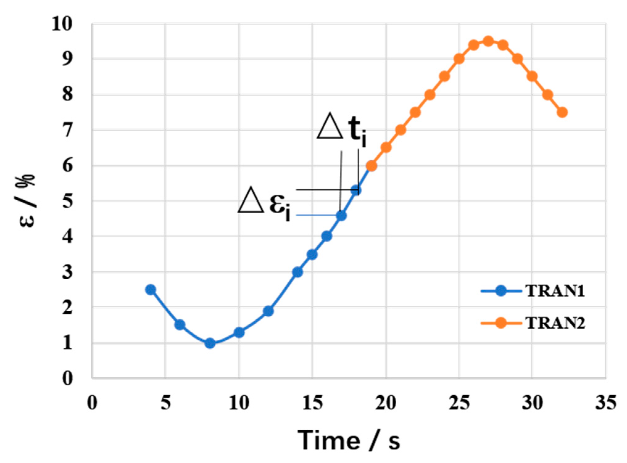
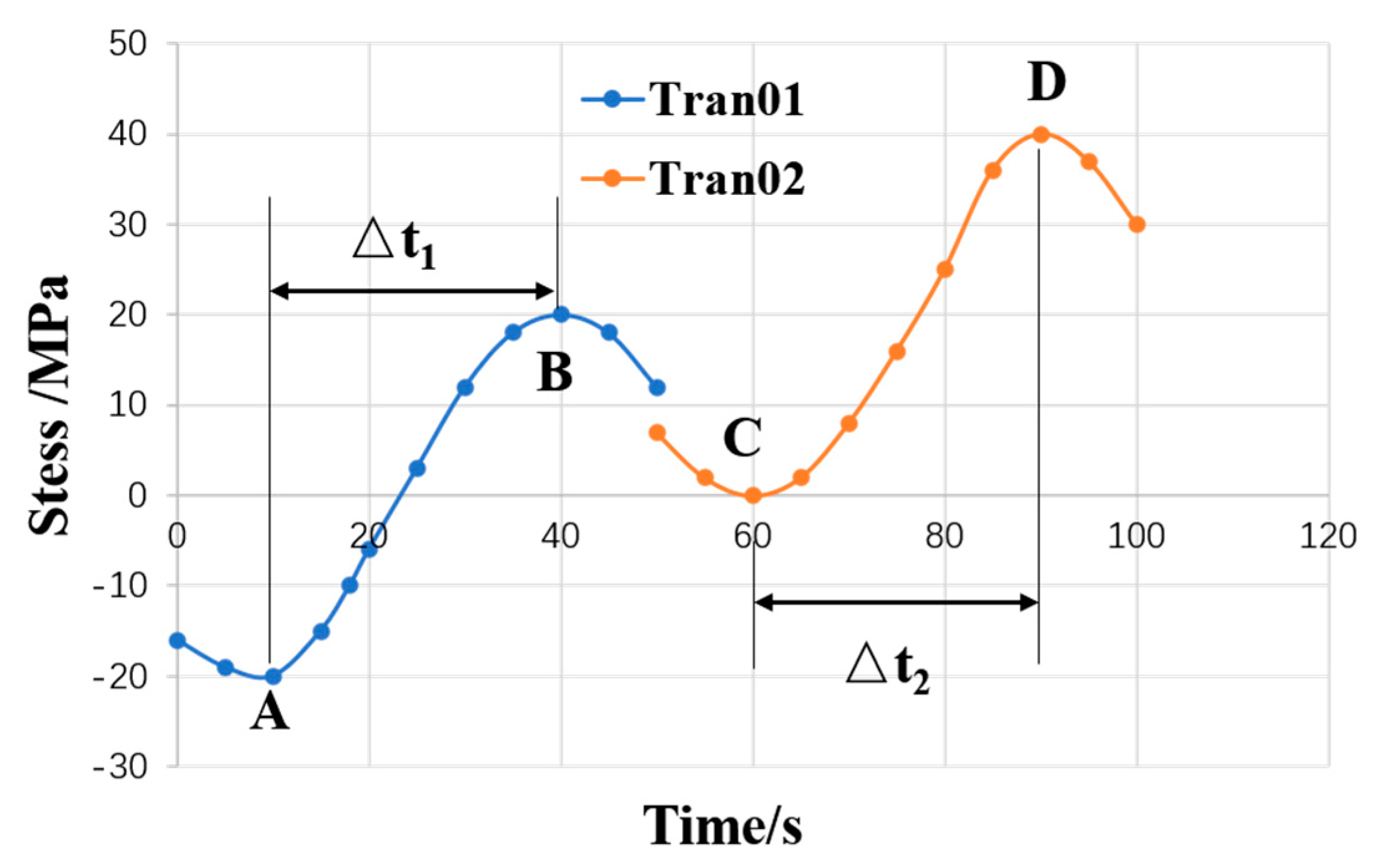
Firstly, in the transient time history, the period when the stress increment is positive is selected to determine the maximum stress and minimum stress σ max , x , σ max , y , σ max , z , σ max , x y , σ max , y z , σ max , x z , σ min , x , σ min , y , σ min , z , σ min , x y , σ min , y z , σ min , x z ;
(2)
The stress rates σ ˙ i of the six components are determined by dividing the corresponding time increment;
(3)
According to the six components of the stress rate tensor, the rate of stress intensity σ ˙ SI is determined;
(4)
The strain rate and strain amplitude are then calculated as
ε ˙ = σ ˙ SI E K e
Δ ε = σ SI E K e
The term ε max ε min in Equation (20) can be calculated by Equation (22).

4. The Simple Model Analysis and Comparison

4.1. EPRI Guideline Case

In this subsection, fatigue analysis of a typic nozzle is performed according to the sample problem 1 in the EPRI guideline, including the environmentally assisted fatigue effect. Axial constraint is applied in the right side of the model, and the hydrostatic end force is applied in the left side of the model. Temperature and pressure transients are applied on the inner surface of the model, which is shown in red in Figure 3. The analysis from Section 1 is performed on the piping made of austenitic stainless steel (TP316), and that from Section 2 is performed on the vessel nozzle part made of low alloy steel (SA-508, Grade 2, Class 2), as shown in Figure 3. The material properties and fatigue curves are taken from the nuclear code ASME code 2007 edition [12], and the sulfur content of low-alloy steel is 0.025%. Three transients are considered in the calculation for sample 1, as shown in Table 1, including the changes in temperature, pressure, heat transfer coefficient and external load with time. It is assumed that the free oxygen in the coolant is 0.15 ppm under each transient. The temperature, pressure and heat transfer coefficient are applied on the inner surface of the model, and the load is applied on the leftmost end of the model. The difference with sample 2 is the transient data, and there are four transients whose detailed parameters are shown in the literature [5].
The first stage of the analysis procedure is to calculate the fatigue usage factors by using the air design fatigue curve, and the second stage is the application of the detailed method approach to obtain the final results with the environment effect.
This paper executes the two stages and gives the calculation results as shown in Table 2 and Table 3, where GD represents the calculation results listed in the guideline [10] issued by EPRI. TranA and TranB represent one of the two transients of fatigue combination, respectively. It should be noted that the fatigue usage factor increases 3.2-fold for austenitic stainless steel, and 8.5-fold for low-alloy steel with or without the application of Fen. Compared with the results of the guidelines (GD), relatively good agreement is achieved, and the difference may be caused by the different stress time histories due to mesh sensitivity, transient stress histories, engineer tools, etc.

4.2. The Influence of Different Fen Expressions

As mentioned in Section 2.2, there are some differences in the detailed expressions of Fen in different countries and reports. Table 4 tabulates the effect of Fen expression on environmental fatigue life by using the Fen expressions of JNES, CR6909 Rev.0, and CR6909 Rev.1, which are listed in Section 2.2. The reactor water’s dissolved oxygen content is 0.005 ppm. By comparison, the result for the environmental fatigue as calculated by NUREG/CR-6909 Rev.1 is the smallest, which may be caused by the improvement in Fen expression based on more experimental data. The result of the JNES calculation is the largest, which shows that JNES in Japan achieves a more rigorous assessment of environmental fatigue.

4.3. The Influence of Different Strain Rate Approaches

The finite element model and transients for the analysis are given in Section 3.1. The calculation results of Fen obtained by different strain rate approaches are given in Table 5. To compare with the results of GD, the model of example 1 and the transient calculation of Fen are adopted, wherein “Detailed-GD” refers to the calculation results given by the detailed method in the EPRI guidelines, “Detailed-RPP3” refers to the calculation results given by the detailed method in RCC-M-2017 Edition Section VI-RPP3, and “Simplified method” represents the Fen results calculated by using the simplified algorithm given in Section 3.1. It is found that the calculation results of the average algorithm are greater than those of the rate increment algorithm. Since the time history is not considered in the simplified method, the calculation result is more conservative. However, considering that the average method has to employ a complex procedure for the calculation of average strain rate and strain range through stress, the corresponding results are not as accurate as those of the detailed strain rate method. Therefore, it is recommended to adopt the detailed method for environmental fatigue assessment.

5. Reactor Pressure Vessel and Steam Generator EAF Evaluation

5.1. Environmental Fatigue Calculation of RPV

Based on the study of the calculation method of the environmental fatigue correction factor, this subsection carries out the environmental fatigue analysis by using the inlet nozzle structure of the reactor pressure vessel with the operation transient of the nuclear power plant. The number and data of each transient should take into account the actual operation and design transients of the power plant. The material of the inlet nozzle and the reactor pressure vessel is SA-508 Class 3 Grade 1, and the material of the safety end is SA-182 F316. Temperature and pressure are altered on the inner surface. The finite element method with target sections is shown in Figure 4. Node 14,054 is the inner node of Section 1, and the material is stainless steel. Node 8089 is the inner node of Section 2, and the material is low-alloy steel.
According to the operation transients of the RPV in nuclear power plant, the operation transients are divided into 14 groups. Based on the characteristics of design transient power variation, 37 design transients are divided into a corresponding 14 groups. The envelope values of the temperature and pressure of operation, and the design transients, are calculated, and the number of transients is processed by the method given in Section 2.1.
For the EAF analysis of the inlet nozzle of a nuclear power plant reactor’s pressure vessel, five methods are adopted to consider the effect of coolant environmental fatigue. The subscript “GD” indicates the detailed method supplied by the EPRI guideline, and “RPP” represents the detailed method provided by RCC-M-2017 Edition Section VI- RPP3. “V0” and “V1” represent the versions of Fen expression, which are 2007 or 2018, respectively. For example, the Fen value was calculated by GD using Fen expression of the NUREG/CR-6909 Rev.0, is expressed as Fen-GD-V0, and the cumulate usage factor is marked as CUFGD-V0. The CUFCONSER is calculated by assuming conservative parameters. This method directly conserves the values of parameters in Fen’s expression. For austenitic stainless steel, the maximum value of transient temperature is 294 °C, and the strain rate is less than 0.0004%/s, so the maximum value of Fen is 10.3. For low-alloy steel, the maximum temperature is 294 °C, the sulfur content is 0.025 wt. %, the oxygen content is 0.1 ppm, and the strain rate is less than 0.0004%/s conservatively, and thus the responding maximum value of Fen is 12.18.
As shown in Table 6, the calculation method of the strain rate has little influence on the results, in which the biggest change is from 4.17 to 3.96 for low-alloy steel, with a change of about 5.1%, while the biggest change is 1.9% for the austenitic stainless alloy. Most of the results obtained by GD are slightly larger than those by RPP. The difference in the expression has a great influence on the results. For austenitic stainless steel, the result of the expression in Rev.1 is less than that in Rev.0. However, for low-alloy steel, the changing trend is the opposite. It can be seen from the Figure 5 that the results of Rev.1 expression are significantly greater than those of Rev.0, and the maximum difference increases by 62.6%. Then, the fatigue results are multiplied by Fen to obtain the fatigue usage factor, considering the environmental effect.
The fatigue results before and after considering the coolant environment are given in Table 7. The conservative calculation is the simplified method listed in the last column, but the results obtained by this method are nearly double those obtained by the detailed strain method. The detailed strain method is helpful to more accurately evaluate the influence of the coolant environment on the fatigue life of key equipment in the nuclear power plant.
Considering the influence of the environment, the fatigue usage factor of low-alloy steel exceeds the limit value of 1.0. However, whether or not to consider the effect of environmental fatigue, due to the use of stainless steel cladding in the interior of low-alloy steel to prevent the corrosion of low alloy steel caused by the coolant, is still a controversial issue. For austenitic stainless steel, even if the simplest method is adopted, the service factor of environmental fatigue here is far less than 1, so there is no risk of environmental fatigue for the stainless steel of the reactor pressure vessel’s inlet nozzle.

5.2. Environmental Fatigue Calculation of Steam Generator

In this part, the influence of the coolant environment on fatigue life under the transient design is analyzed by using the divider plate model of the steam generator’s lower head. Since the strain rate detailed method can more accurately calculate the transformed strain rate considering the strain increment history, the detailed method is adopted to evaluate the influence of the coolant environment on the fatigue life in this section.
In this model, the divider plate is made of nickel-based alloy, while the lower head, cylinder, and tube plate are made of low-alloy steel. The physical properties and fatigue curves of the steel are taken from the nuclear code ASME. The temperature and pressure of the primary side hot section are applied on one side of the lower head, the temperature and pressure of the primary side hot section are applied on the other side, the secondary side temperature and pressure are applied on the upper part of the tube sheet and the inner wall of the cylinder, and a pressure difference of 0.5 MPa is considered for the cold and hot sections of the primary side. All boundary conditions are shown in Figure 6.
The resulting interaction of the divider plate with the tube sheet and channel head is the major source of stress in the plate. The pressure causes the dilation of the channel head, which stretches the divider plate in turn. Another source of divider plate stress is the pressure differential across it. Thermal stresses are induced partly in the divider plate by the mismatch between the coefficients of the thermal expansions of the Inconel divider plate and the carbon steel channel head and tube sheet. The temperature difference due to the hot leg and cold leg is also another main source. The primary temperature and pressure transients used in fatigue analysis are the same as those in Section 5.1.
Table 8 shows the Fen values of the steam generator channel head divider plate. Compared with the GD method, some results calculated by the RPP3 method are increased, while others are decreased. The maximum difference is 2.11 to 1.88, which is reduced by 16.7%. The influence of expression is that all results of the V1 version are reduced. The biggest difference is from 2.26 to 1.83, which causes a decrease of 19.1%. Table 9 shows the fatigue results considering the environmental impact. Since the fatigue usage factor in the air is small, the environmental fatigue analysis result considering coolant is still less than 1, so there is no risk of environmental fatigue in this component. For PWR, assuming the temperature is 325 °C, the maximum value of Fen for austenitic stainless steel is 12.8, and that of nickel-based alloy is 15.4. Therefore, if the fatigue usage factor of the austenitic stainless steel parts in the air is less than 0.065, the influence of environmental fatigue can be ignored; if the fatigue usage factor of nickel-based alloy parts in the air is less than 0.078, the influence of environmental fatigue can be ignored.

6. Summary

The conclusions are summarized as follows:
(1)
By comparing the detailed method with the average strain and conservative method, the detailed strain rate method can more accurately evaluate the environmental fatigue life of the structure and can be applied to the analysis of the metal fatigue time-limit aging of key components in the nuclear power plant;
(2)
Compared with Fen expressions of JNES, CR6909 Rev.0 and CR6909 Rev.1, NUREG/CR-6909 Rev.1 has the smallest result and JNES has the largest result, which indicates that JNES in Japan allows a more rigorous assessment of environmental fatigue;
(3)
The influence of the Fen expression for low-alloy steel is opposite to that for austenitic stainless steel and nickel-based alloy. The calculation results of version 1 are greater than those of version 0, and the maximum difference increases by 62.6%;
(4)
Compared with the GD method, the RPP3 method has a lesser effect on the maximum differences between the austenitic stainless steel and low-alloy steel at the inlet nozzle of the pressure vessel, which are 1.9% and 5.1%, respectively. For the nickel-based alloy of the steam generator’s divider plate, the maximum difference is 16%;
(5)
If the fatigue usage factor of austenitic stainless steel in the air is less than 0.065 and that of nickel-based alloy is less than 0.078, the influence of environmental fatigue can be ignored.
It must be pointed out that only numerical investigations are carried out on the different analysis methods of environmental fatigue correction factors in the work, and the environmental fatigue test will be performed to verify the applicability of the calculated results in further work.

Author Contributions

Methodology, F.X., X.B. and L.J.; supervision, Y.Z.; writing—original draft, X.S.; writing—review and editing, H.X. and Q.K. All authors have read and agreed to the published version of the manuscript.

Funding

This research was funded by the National key research and development program (2016YFB1102601), National Natural Science Foundation of China (12072295,11905215).

Institutional Review Board Statement

Not applicable.

Informed Consent Statement

Not applicable.

Data Availability Statement

Not applicable.

Conflicts of Interest

The authors declare no conflict of interest.

References

  1. Omesh, C.K.; Shack, W.J. Effect of LWR coolant environments on fatigue S-N curves for carbon and low-alloy steel: ANL/ET/CP/89687. In Proceedings of the American Society of Mechanical Engineers (ASME) pressure vessels and piping conference, Montreal, QC, Canada, 21–26 July 1996. [Google Scholar]
  2. He, Y.; Cao, M.; Yao, W. Overview of LWR environment assisted fatigue issues for primary components and piping of NPPs. Nucl. Eng. Des. 2011, 32, 35–39. [Google Scholar]
  3. Sun, H.; Wang, C.; Xiong, D. Effect of PWR coolant environment on the fatigue life of reactor equipment materials. Chin. J. Nucl. Sci. Eng. 2014, 34, 482–487. [Google Scholar]
  4. Shao, X.; Xie, H.; Zhang, L. Analysis of fatigue time limit aging of reactor pressure vessels. Nucl. Eng. Des. 2020, 41, 60–64. [Google Scholar]
  5. NRC Regulatory Guide 1.207. NRC Guidelines for Evaluating Fatigue Analyses Incorporating the Life Reduction of Metal Components Due to the Effects of the Light-Water Reactor Environment for New Reactors; NRC: North Bethesda, MD, USA, 2007. [Google Scholar]
  6. Argonne National Laboratory. Effect of LWR Coolant Environments on the Fatigue Life of Reactor Materials: NUREG/CR6909 ANL-06/08; Argonne National Laboratory: Lemont, IL, USA, 2007. [Google Scholar]
  7. Higuchi, M.; Iida, K. Fatigue Strength Correction Factors for Carbon and Low-Alloy Steels in Oxygen-Containing high-Temperature Water. Nucl. Eng. Des. 1991, 129, 293–306. [Google Scholar] [CrossRef]
  8. Argonne National Laboratory. Effect of LWR Coolant Environments on the Fatigue Life of Reactor Materials: NUREG/CR6909 ANL-12/60; Argonne National Laboratory: Lemont, IL, USA, 2018. [Google Scholar]
  9. Higuchi, M.; Sakaguchi, K. Final proposal of environmental fatigue life correction factor (Fen) for Structural materials in LWR water environment. In Proceedings of the 2007 ASME Pressure Vessels and Piping Division Conference, San Antonio, TX, USA, 22–26 July 2007. [Google Scholar]
  10. EPRI. Guidelines for Addressing Environmental Effects in Fatigue Usage Calculations; 2012 Technical Report 1025823; EPRI: Palo Alto, CA, USA, 2012. [Google Scholar]
  11. RCC-M. Design and Construction Rules for Mechanical Components of PWR Nuclear Islands, 2017 Edition Section VI-Probationary Phase Rules RPP3; AFCEN: Paris, France, 2017. [Google Scholar]
  12. ASME. ASME Boiler and Pressure Vessel Code: 2007 + 2009 Addenda Edition, Section II Materials, Part D—Properties; ASME: New York, NY, USA, 2009. [Google Scholar]
Figure 1. Diagram of the detailed strain rate increment method.
Metals 11 00233 g001
Figure 2. Diagram of the simplified average strain method.
Metals 11 00233 g002
Figure 3. Finite element model with load, boundary conditions, and target cross-sections.
Metals 11 00233 g003
Figure 4. Finite element model and target cross-sections of RPV inlet nozzle.
Metals 11 00233 g004
Figure 5. Fen values of Node 8089 with each transient combination.
Metals 11 00233 g005
Figure 6. Finite element model and boundary conditions of the divider plate in the steam generator.
Metals 11 00233 g006
Table 1. Transient data of temperature, pressure, and external load vs. time in sample 1.
TransientTime T/sTemperature/°CHeat Transfer/(W·m−2·K−1)Pressure/MPaMoment/(kN·m)
Tran1
N = 20
0315.6883115.513−338.97
5315.6883115.513−338.97
20537.888316.895112.99
10037.888316.895112.99
1200315.6883115.513−338.97
3000315.6883115.513−338.97
Tran 2
N = 50
0260.0883110.342−282.48
5260.0883110.342−282.48
405315.6883115.513112.99
1500315.6883115.513112.99
1900260.0883113.790−282.48
2500260.0883113.790−282.48
Tran 3
N = 20
0232.288313.103−225.98
5232.288313.103−225.98
14,00021.188313.034169.49
16,00021.188312.758169.49
20,000176.788312.758−225.98
24,000176.788312.758−225.98
Table 2. Environmental fatigue calculation results of sample problem 1.
SectionPairTranATranBUiFenFen-GDUi·FenCUF-water
11110.726765.02715.11663.65354.3092
2220.166843.93043.98540.65575
33302.72252.71530
Table 3. Environmental fatigue calculation result of sample problem 2.
SectionPair UiCUF-airFenUi·FenCUF-waterCUF-water-GD
110.67061.34984.793.21155.70885.4521
20.55803.872.1618
30.07562.660.2010
40.02562.490.0637
50.01542.710.0418
60.00276.370.0173
70.00128.090.0094
80.00021.000.0002
90.00054.090.0022
210.09140.13111.601.05941.23811.5979
20.03494.510.1574
30.00156.740.0102
40.00152.760.0041
50.00113.530.0040
60.00024.090.0008
70.00025.040.0008
80.00018.610.0009
90.00018.600.0005
Table 4. Results of Fen under different expressions.
TransientNUREG/CR-6909Rev.0NUREG/CR-6909Rev.1JNES
15.02714.28567.0267
23.93043.03065.7055
32.74701.90714.1400
Table 5. Results of Fen under different strain rate approaches.
TransientsDetailed-GDDetailed-RPP3Simplified Method
15.02714.9916.5470
23.93043.8744.9870
32.74702.7183.5420
Table 6. Fatigue usage factor in air and the Fen value of RPV inlet nozzle.
NodePairTranATranBUiFen-GD-V0Fen-GD-V1Fen-RPP-V0Fen-RPP-V1
14054
(F316)
1160.00056 8.13 7.13 8.05 7.05
26150.00025 6.81 5.97 6.68 5.86
3660.00044 6.81 5.97 6.68 5.86
8089
(SA-508)
1130.15256 6.18 9.95 5.98 9.57
2150.02080 6.42 10.41 6.23 10.05
3560.00008 5.01 7.35 5.05 7.23
4660.01322 5.69 8.14 5.81 7.99
5560.00002 5.01 7.35 5.05 7.02
613140.00016 2.02 2.19 2.02 2.10
75110.00024 3.81 5.59 3.73 5.44
810110.00066 2.68 3.63 2.59 3.47
910120.00029 5.77 8.98 5.65 8.64
1013130.00150 2.02 2.22 2.02 2.14
1113140.00006 2.02 2.19 2.02 2.10
1210110.00002 2.98 4.17 2.86 3.96
1310150.00001 7.04 11.46 7.05 11.47
Table 7. The cumulate fatigue usage factor in air and water environments using different strain rate approaches and Fen expressions of RPV inlet nozzle.
NodeCUF-airCUF-water-GD-V0CUF-water-GD-V1CUF-water-RPP-V0CUF-water-RPP-V1CUF-water-CONSER
14,0540.00125 0.00931 0.00816 0.00917 0.008040.01288
80890.18962 1.15985 1.85393 1.12715 1.78466 2.30957
Table 8. Fen results of the divider plate in the steam generator.
NodeTranATranBUiFen-GD-V0Fen-GD-V1Fen-RPP-V0Fen-RPP-V1
695872310.00146 3.16 2.60 3.39 2.80
2370.00154 3.15 2.58 3.37 2.78
2340.00012 3.30 2.70 3.56 2.92
2260.00066 3.27 2.68 3.55 2.92
2360.00003 3.18 2.61 3.52 2.89
21360.00003 2.66 2.17 2.37 1.92
21220.00002 2.65 2.16 2.35 1.91
14210.00030 2.77 2.26 2.32 1.88
3210.00027 2.62 2.13 2.26 1.83
130.00009 3.27 2.68 3.56 2.94
Table 9. Cumulate fatigue usage factor of the divider plate in a steam generator.
NodeCUF-airCUF-water-GD-V0CUF-water-GD-V1CUF-water-GD-RPP-V0CUF-water-GD-RPP-V1
69,5870.00452 0.01407 0.01154 0.01474 0.01214
58,1400.00146 0.00423 0.00346 0.00350 0.00287
69,4890.00341 0.01054 0.00864 0.01093 0.00901
Publisher’s Note: MDPI stays neutral with regard to jurisdictional claims in published maps and institutional affiliations.

