1. Introduction
Hydraulic fracturing is a major technique to produce economically from unconventional oil and gas reservoirs. Numerous researches have been conducted in order to optimize hydraulic fracturing operation to maximize oil and gas production from unconventional reservoirs [
1,
2,
3,
4,
5]. Connecting hydraulic fractures with existing natural fracture network in formation matrix enhances the efficiency of stimulation process and increases resultant hydrocarbon production rate. Unlike the conventional hydraulic fracturing process, thermal Shock is a new technique to initiate fractures and to connect the existing fractures and fissures in the rock matrix by altering the effective stresses around the wellbore or at the existing fractures surface areas.
Researchers have been investigating thermal shock technique since the 1970s. Using analytical and experimental methods, Finnie et al. [
6] evaluated thermal cracking resulting from cooling with liquid nitrogen. In that experiment, they injected liquid nitrogen into 5 cm long by 1 cm diameter central holes in 10 cm cubes of Solnhofen limestone. They concluded that rapidly decreasing the temperature at the surface creates tensile stresses that initiate and propagate cracks in the rock. Geyer and Nemat-Nasser [
7] thermally induced parallel edge cracks in a half-plane consisting of brittle material. A glass plate was heated to a uniform temperature and then exposed to a liquid bath that is cooled by dry ice. When the edge of the plate came into contact with the bath of cold liquid, the edge became a thermal boundary layer for the glass as a whole. The boundary layer thermally contracted, producing tensile cracks. These cracks propagated perpendicularly to the cooled edge. Grundmann et al. [
8] discussed the successful field application of cryogenic fracturing. In this study, liquid nitrogen was used to stimulate a well drilled in the unconventional reservoir (Devonian shale) in Eastern Kentucky. They concluded that more tests are required to improve the fracture-flow conductivity while using thermal shock. Kim and Kemeny [
9] conducted laboratory tests to study whether rapid cooling damages rock or not. Granite and diabase with ore veins samples were tested in this study. The rock was slowly heated to 100 °C and then cooled it rapidly. The results showed that crack growth caused by thermal shock occurred in some rock types. They concluded that rapid cooling of a rock surface results in a non-uniform temperature distribution, which builds considerable thermal stresses. These stresses are due to tension on the surface of the rock and compression in center of its body. These stresses may grow the present crack network or heal the cracks depending on the type of rock. Kocabas [
10] presented a transient analytical model to study the effect of a non-isothermal water injection on the temperature and stress distribution around the wellbore. The results showed that the thermoelastic changes in the cooled zone could highly affect the surrounding stress fields. He reported that this phenomenon may induce new fracture or propagate the existing ones. Tarasovs and Ghassemi [
11] developed a simulation model to examine the process of thermal stimulation. The results indicated that the secondary cracks were mainly determined by the temperature distribution in a geothermal reservoir. Kumar and Gutierrez [
12] also developed a two-dimensional (2D) transient heat flow model to estimate the thermal induced effects on fracture geometry. A cold fluid was injected into hot rocks and caused the rocks surrounding the fracture to become relatively cool. This resulted in a change in tensile stresses and an expansion of the fracture volume. Tran et al. [
13] used a 2D-plain-strain simulation model to study effects of the temperature difference between an injected cold fluid and a hot reservoir model on crack initiation. The results demonstrated that thermal stresses are the dominant cause of secondary fractures and that the initiation and propagation of secondary cracks is possible, even with the short-term injection of hydraulic fracture fluid.
In the last few years, several experimental works have been conducted to study the cryogenic fracturing technology and its applications. Alqahtani [
14] presented Cryogenic fracturing experimental tests. The tests were carried out on concrete, tight sandstone, and Niobrara shale samples while using liquid nitrogen. The results showed that cryogenic fracturing has not only a positive effect on rock permeability especially shale samples, but also has almost no formation damage potential. Zhao et al. [
15] conducted rock mechanical properties test under cryogenic conditions (rock samples were subjected to liquid nitrogen). The results showed that both shear strength and tensile strength of the rock samples significantly decreased. They concluded that the thermal shock that was caused by the cryogenic treatment could create new microfractures and extend the existing microfractures, and consequently enhance the production capacity of the well. Yao et al. [
16] also conducted laboratory cryogenic fracturing experiments to investigate the ability of enhancing the permeability of synthetic rock samples (concrete). 20.3-cm rock cubic samples were used in these experiments. Eight tiny thermocouples were embedded in their diagonals to monitor the temperature change during the tests. The samples were under triaxial stresses and in the meantime, liquid nitrogen was circulated into the samples through 15.24-cm-deep holes. The results showed that the permeability of the affected area was increased.
Cryogenic fracturing is a stimulation technology that uses cryogenic fluids like liquid nitrogen to fracture unconventional oil and gas reservoirs and it reduces the formation damage, as it is a waterless technology [
17,
18,
19]. Smith [
20] also reported that using the Earth’s geothermal energy to warm cryogenic flood fluids injected into unconventional reservoirs causes an increase in reservoir pressure and this rise in pressure results in the production of fluids from the reservoirs.
Thermal Shock is a technique in which a fluid at a low temperature is injected into a hot reservoir. Temperature difference between the injected fluid and the wall of the main fracture of the wellbore results in an increase in tensile stress [
21,
22,
23,
24,
25] and a decrease in the maximum horizontal effective stress (stress in the direction parallel to the main fracture in case of transvers fracture). If the decrease in maximum horizontal effective stress and the increase in tensile stress are adequate, a secondary crack is initiated. In addition to that, applying thermal shock to rock surface and existing hydraulic fractures will alter the rock mechanical properties (Young’s modulus and Poisson’s ratio) and it creates a secondary fracture network in rock body. This change in rock mechanical properties results in rock brittleness alteration and thus the possible propagation of existing fracture network in rock matrix.
In contrast, the thermal shock technique can cause crack healing instead of crack growth. In crack healing, the crack density of the rock decreases slightly [
26]. When a rock sample is heated slowly, for example, its thermal expansion can fill cracks and voids. Overall healing is expected when the amount of crack healing in the central parts of a rock sample (due to slow heating) exceeds the crack growth near the surface of the sample (due to rapid cooling) [
9].
Factors affecting success of thermal shock technique are listed below [
9,
15,
26,
27,
28,
29]:
Natural fracture network: Existence of natural fracture in a rock decreases the rock tensile strength and assists creating new fractures.
Rapid thermal load: Applying rapid thermal load results in a steep temperature gradient between the body and the surface of rock and helps to create fractures.
Low rock thermal conductivity and high thermal expansion coefficient. These are both rock intrinsic properties.
Brittleness of rock sample: There is a direct relationship between the brittleness of rock sample and successfully creating fractures while using thermal shock technique.
Fracture toughness: There is an inverse relationship between fracture toughness and successfully creating fractures while using thermal shock technique.
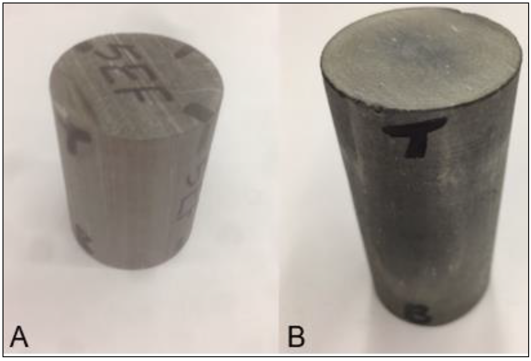
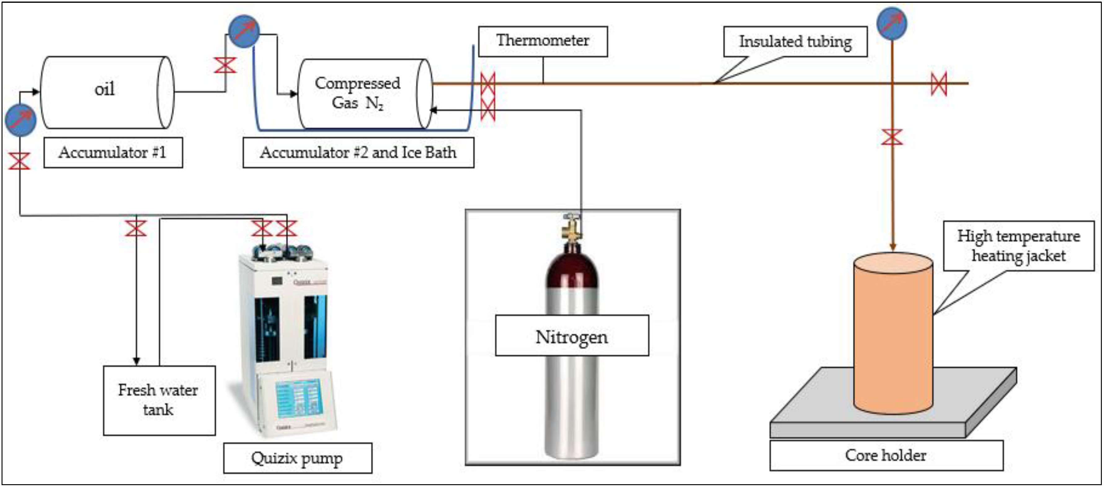
In this study, impacts of thermal shock on porosity, permeability, and mechanical properties of shale rock were examined using two core samples. Three cycles of thermal shock were conducted using cold nitrogen gas on each core sample and porosity, permeability, and acoustic measurement tests were performed on each core sample prior and after completing each cycle of thermal shock.
3. Results and Discussion
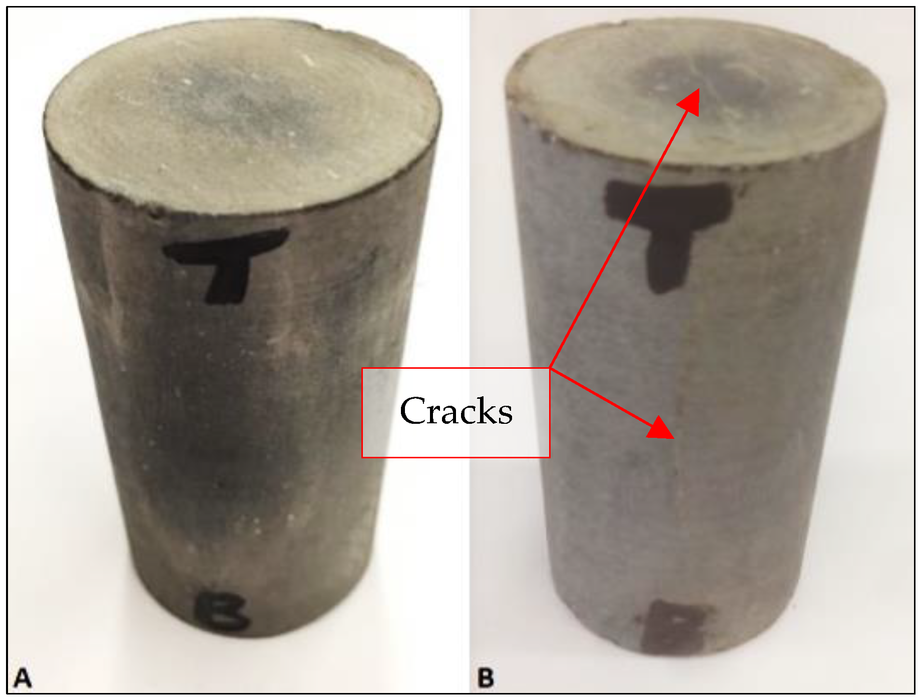
The results that were obtained from the thermal shock tests demonstrated that cracks were created and propagated after applying thermal shock. Thermal shock not only created cracks on the core surface, but it also altered reservoir rock properties (porosity and permeability) and rock mechanical properties (Young’s modulus, Poisson’s ratio, and brittleness ratio).
Significant changes in P velocity were observed after conducting the thermal shocks on both EF#5 and SH#5 core samples, which is an indication of creating induced fractures. Also, when comparing pre-and post-thermal shock test results showed both porosity and permeability enhancement of the core samples. The thermal shock test results revealed that brittleness ratio and fracability index of both core samples were altered after conducting thermal shock cycles. Following are the results analysis for each core sample in terms of porosity, permeability, and rock mechanical properties.
3.1. Porosity Results
It is obvious that there was a slight increase in porosity of EF#5 after 1st and 2nd thermal shock, which is an indication of crack growth (
Table 3). Whereas, after the 3rd thermal shock, the porosity of EF#5 decreased by 0.4%, which might be a sign of crack healing.
The results show that porosity of SH#5 decreased by 4.92% after completing 1st thermal shock and increased by 14.3% after conducting 2nd thermal shock. The third thermal shock resulted in a decrease in porosity by 3.01%. The results are shown in
Table 4. Increase in porosity is an indication of creating new cracks or crack growth in the core sample whereas the decrease in porosity is believed to be due to the crack healing, as explained above.
3.2. Permeability Results
Like porosity measurements, the permeability of the core sample was measured before and after conducting each thermal shock. As shale has ultra-low permeability, it took 3–4 days to measure the permeability using the complex transient method. Following are the permeability results of EF#5 and SH#5.
After the 1st thermal shock, there was an increase in permeability of EF#5 by 32.7% (
Table 5). It is believed that this increase is resulted from crack growth after the hot core was exposed to cold nitrogen. After the 2nd thermal shock, a small increase in permeability was observed, indicating that there was little crack growth. After the 3rd thermal shock, it was observed that the permeability had decreased by 27.1% because of crack healing.
There was a significant improvement in the permeability of SH#5 after the 2nd thermal shock (
Table 6). The percent increase of permeability after the second cycle of thermal shock is 920%, which is an indication of creating a highly induced fracture in the core sample. On the other hand, the 3rd thermal shock had a reverse effect where the permeability decreased by 96.5% as compared to its initial value. It is believed that this reduction in permeability caused by high crack healing.
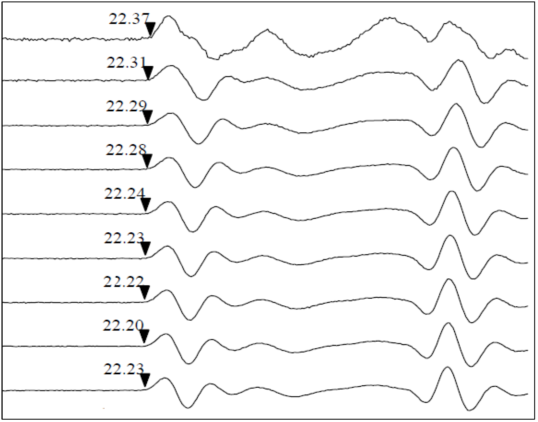
3.3. Axial Velocity Test Results
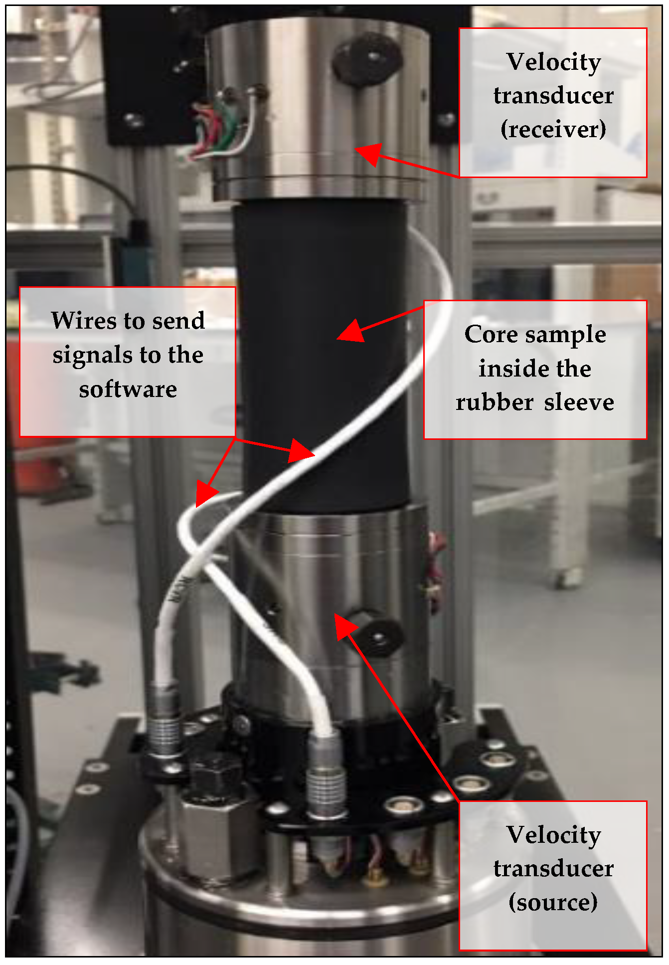
Ultrasonic velocity measurement is used to detect fractures in a rock sample by measuring the P-wave and S-wave velocities. P-wave velocity, Young’s modulus, Poisson’s ratio, rock brittleness, and fracability index results are presented for each core sample individually before and after each thermal shock experiment.
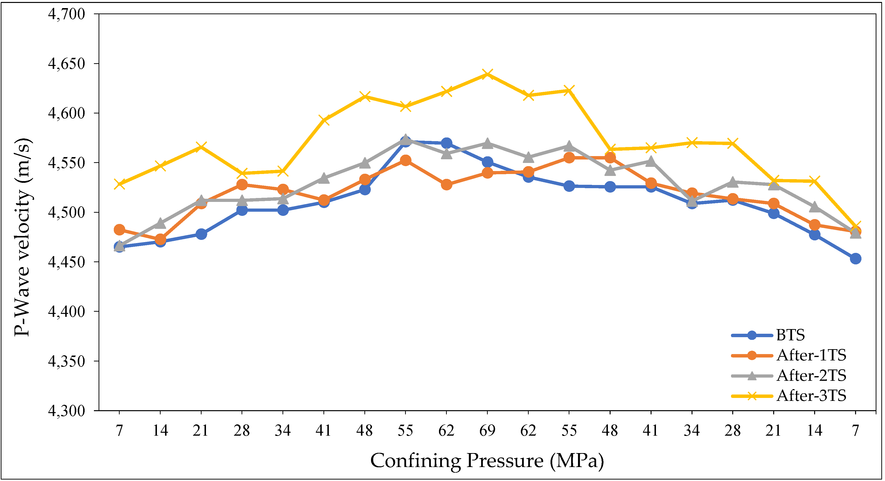
P-wave velocity results of (EF#5) are presented in
Figure 6. It is obvious that there is a direct relationship between the P-velocity and the confining pressure, owing to more compaction at higher confining pressures, which results in faster arrival of the P-wave. Also, the results demonstrate P-velocity alteration after conducting thermal shock technique. After performing the first thermal shock the P-velocity decreased at high confining pressures, which is an indication of induced cracks.
Figure 7 presents the condition of core sample EF#5 before and after the thermal shocks.
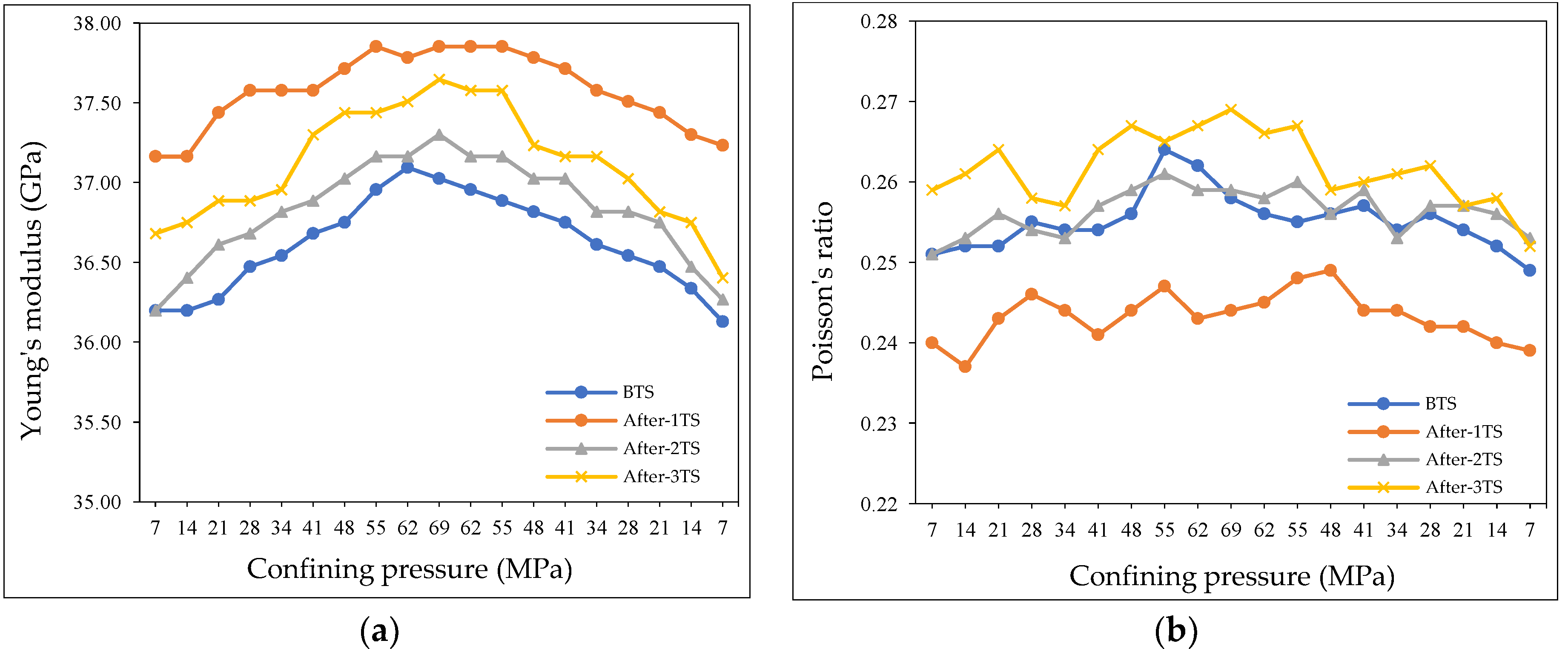
Young’s modulus and Poisson’s ratio results of EF#5 are presented in
Figure 8a. There is a direct relationship between Young’s modulus and confining pressure. Additionally, performing thermal shock on the core sample also altered Young’s modulus of the core sample. For instance, at 68.94 MPa confining pressure, Young’s modulus was 37.8 GPa after completing 1st thermal shock, whereas it was 36.9 GPa before conducting thermal shock.
Thermal shock not only altered the Young’s modulus, but also affected the Poisson’s ratio. It can be seen in
Figure 8b that first thermal shock reduced EF#5 Poisson’s ratio, while both second and third shocks increased it.
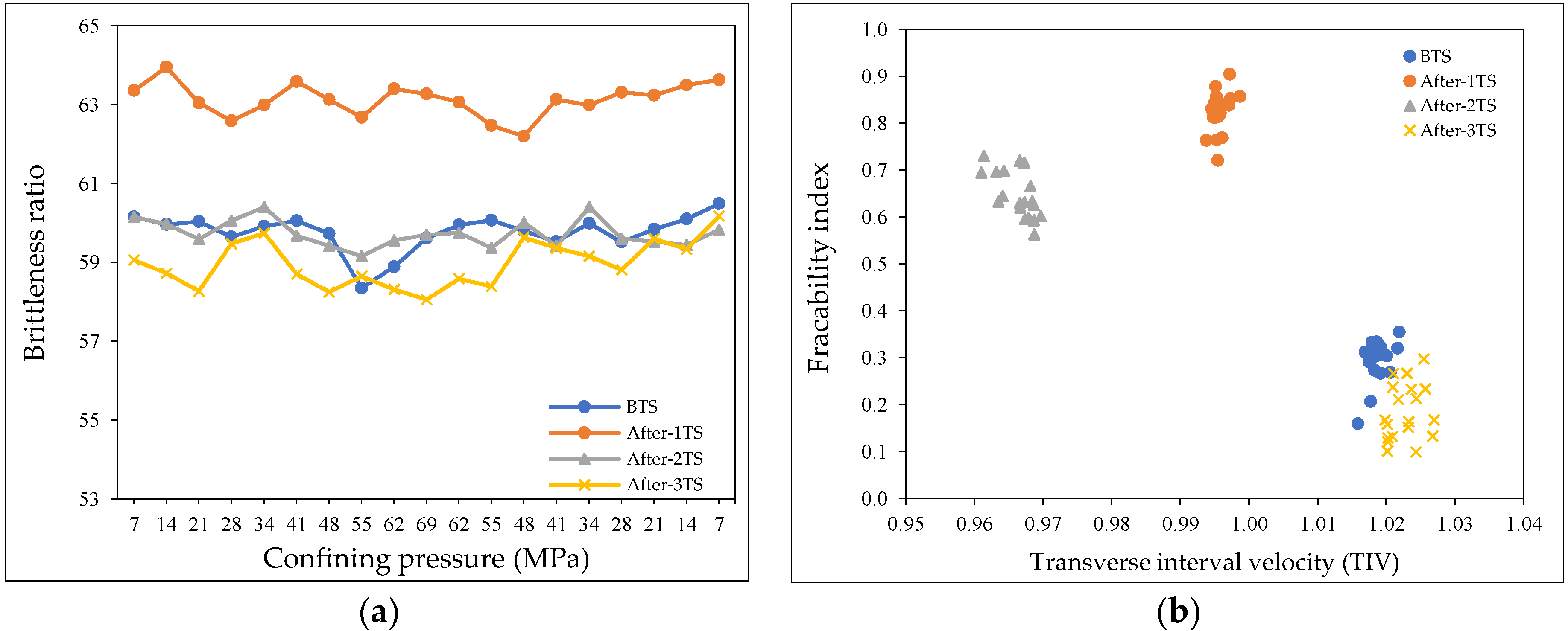
Effects of thermal shock on brittleness ratio of the core sample EF#5 were investigated.
Figure 9a shows the effect of thermal shock on EF#5 where the core became more brittle after the 1st thermal shock. It is obvious that the 1st thermal shock increased the core sample brittleness ratio from about 60 to about 62, while both second and third thermal shocks did not clearly alter the rock brittleness ratio.
As previously explained, the fracability index is the ratio between the brittleness ratio and the transverse interval velocity defined by Buller et al. [
32] (see Equation (3)) The results show that EF#5 has the highest fracability index after completing the 1st thermal shock (
Figure 9b). The fracability index increased by between 0.2 and 0.8.
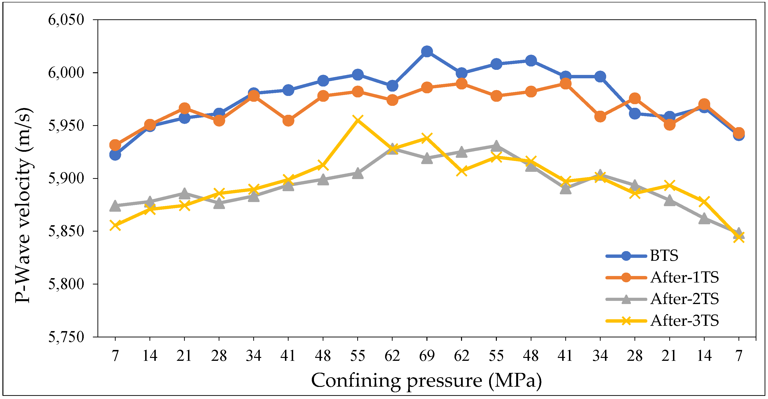
It is obvious that there is a direct relationship between the P-wave velocity of SH#5 and the confining pressure owing to higher rock compaction (
Figure 10). It can also be observed that thermal shock altered P-wave velocity after both the second and third cycles, while the first cycle has insignificant effect on V
p. This reduction in V
p is an evidence of creating new fractures.
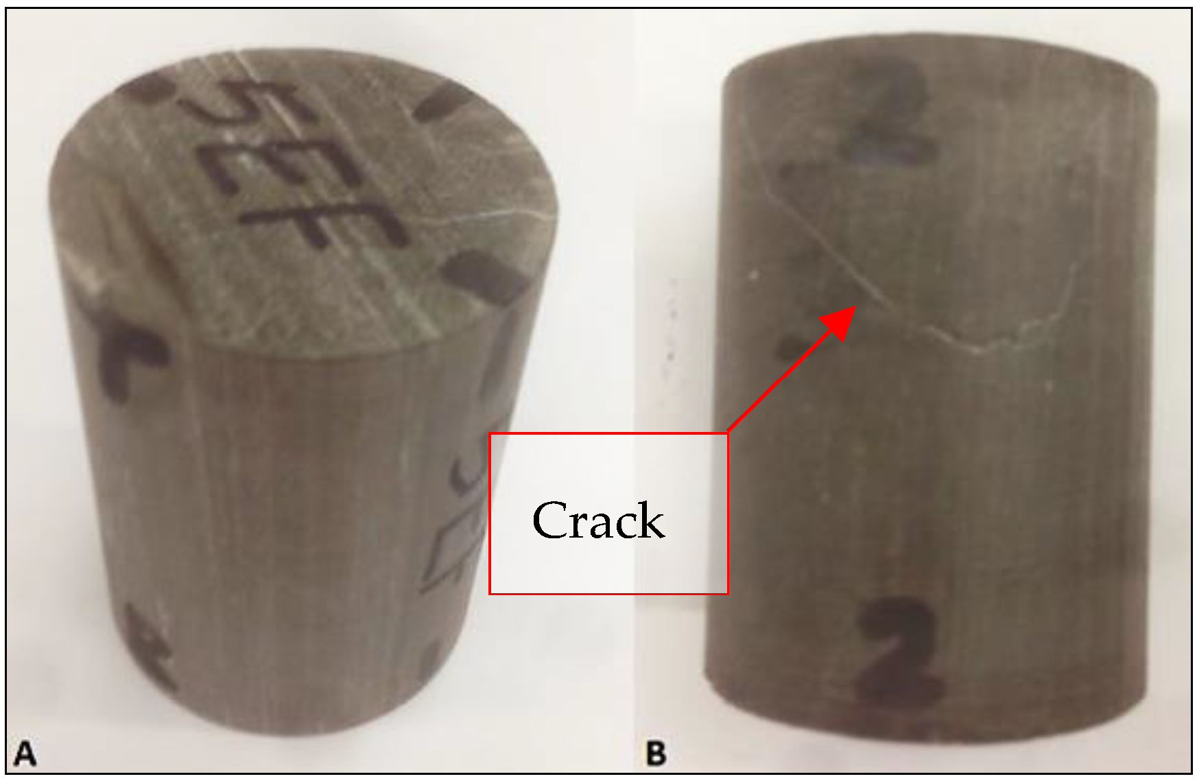
Figure 11 presents the condition of core sample SH#5 before and after the thermal shock, in which the induced fractures after 2nd and 3rd thermal shocks are clear.
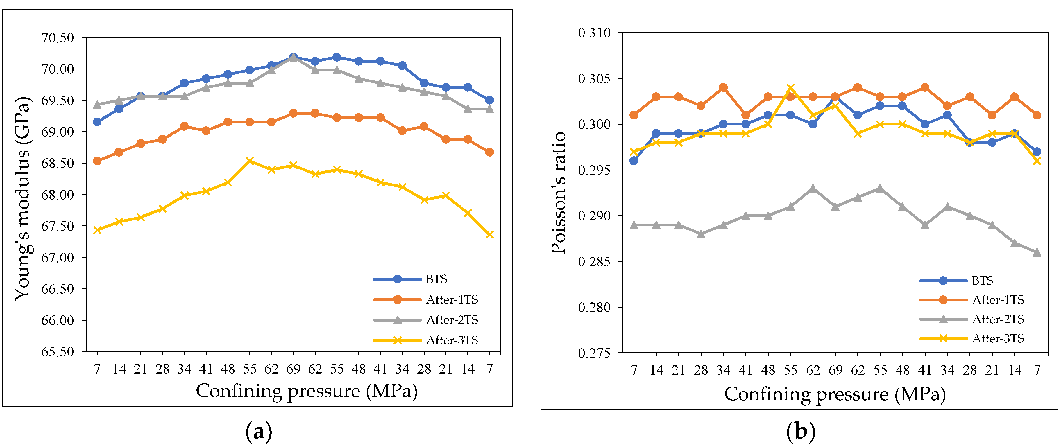
There is a direct relationship between Young’s modulus of SH#5 and confining pressure (
Figure 12a). Unlike core sample EF#5, thermal shock cycles reduced the Young’s modulus of SH#5. Thermal shock not only altered the Young’s modulus, but it also affected the Poisson’s ratio of the core sample. It is clear that Poisson’s ratio decreased to an average of 0.29 after the 2nd thermal shock, while 1st and 3rd thermal shock had small effects on it (
Figure 12b).
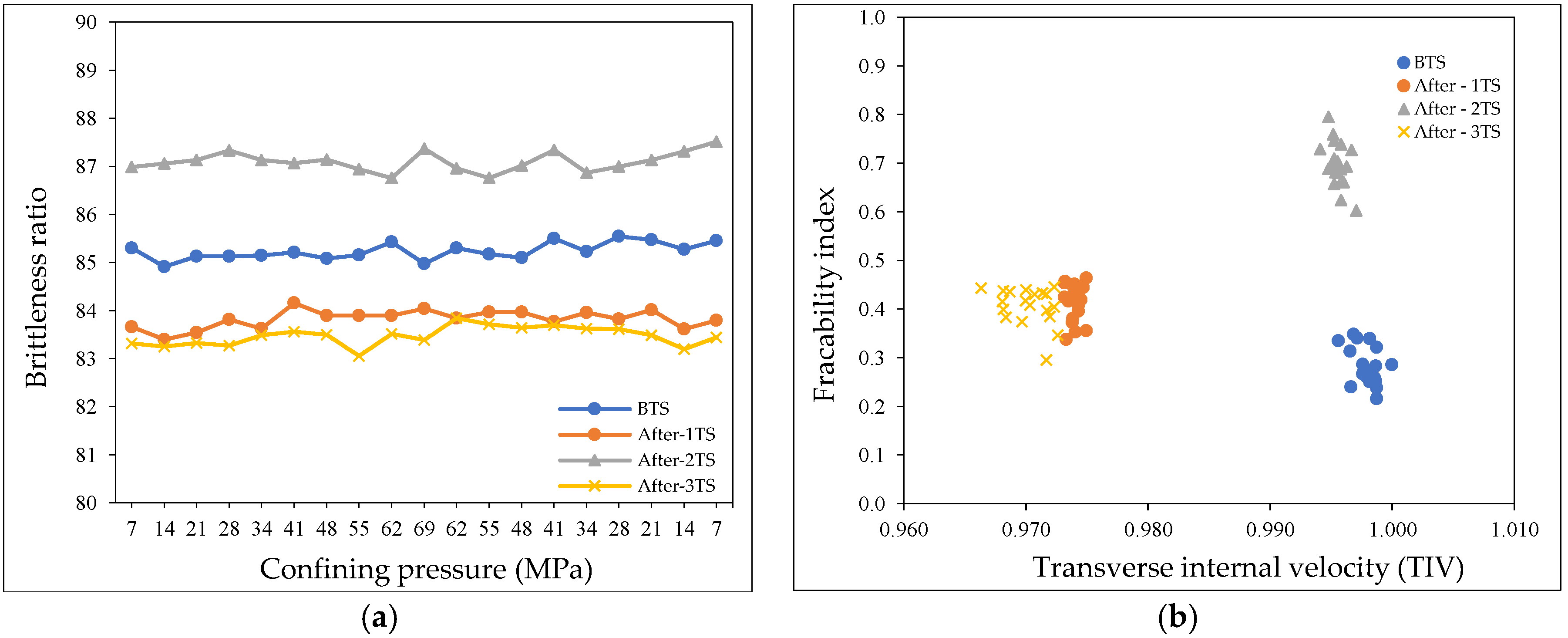
It is also obvious that the core became more brittle after the 2nd thermal shock, whereas the 1st and 3rd thermal shock had an adverse effect on brittleness ratio (
Figure 13a). The brittleness ratio of SH#5 increased by between 2 and 4.
Unlike 1st and 3rd thermal shock, the results show that the 2nd thermal shock clearly increased the SH#5 fracability index (
Figure 13b). After the 2nd thermal shock, TIV was approximately the same as before thermal shock (BTS) (0.1) and the fracability index increased by about 0.6. Whereas, 1st and 3rd thermal shock increased the fracability index by about 0.2.


