

Effective and Realistic Strategies for Large-Scale Liquid Hydrogen Production


Abstract
1. Introduction
2. Hydrogen Pre-Cooling Process
2.1. Open Pre-Cooling Cycle
2.1.1. LN2 Cycle
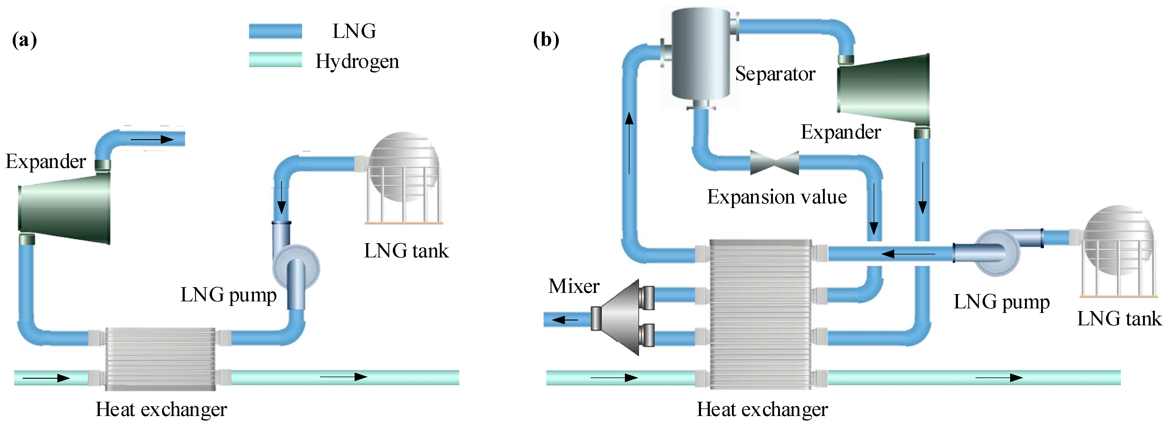
2.1.2. LNG Cycle
2.1.3. Liquid Air Cycle
2.2. Closed Pre-Cooling Cycle
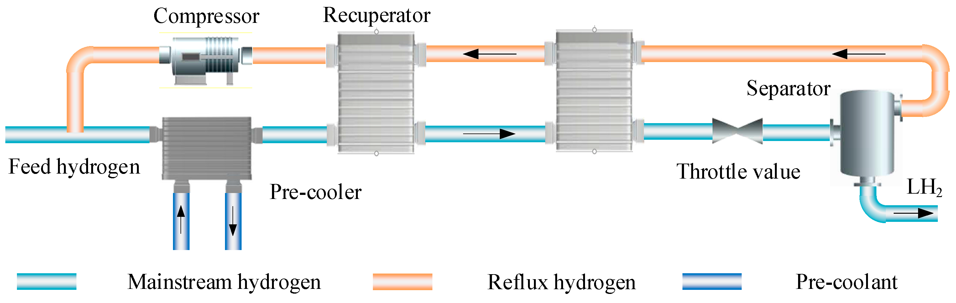
2.2.1. Reverse Brayton Refrigeration Cycle
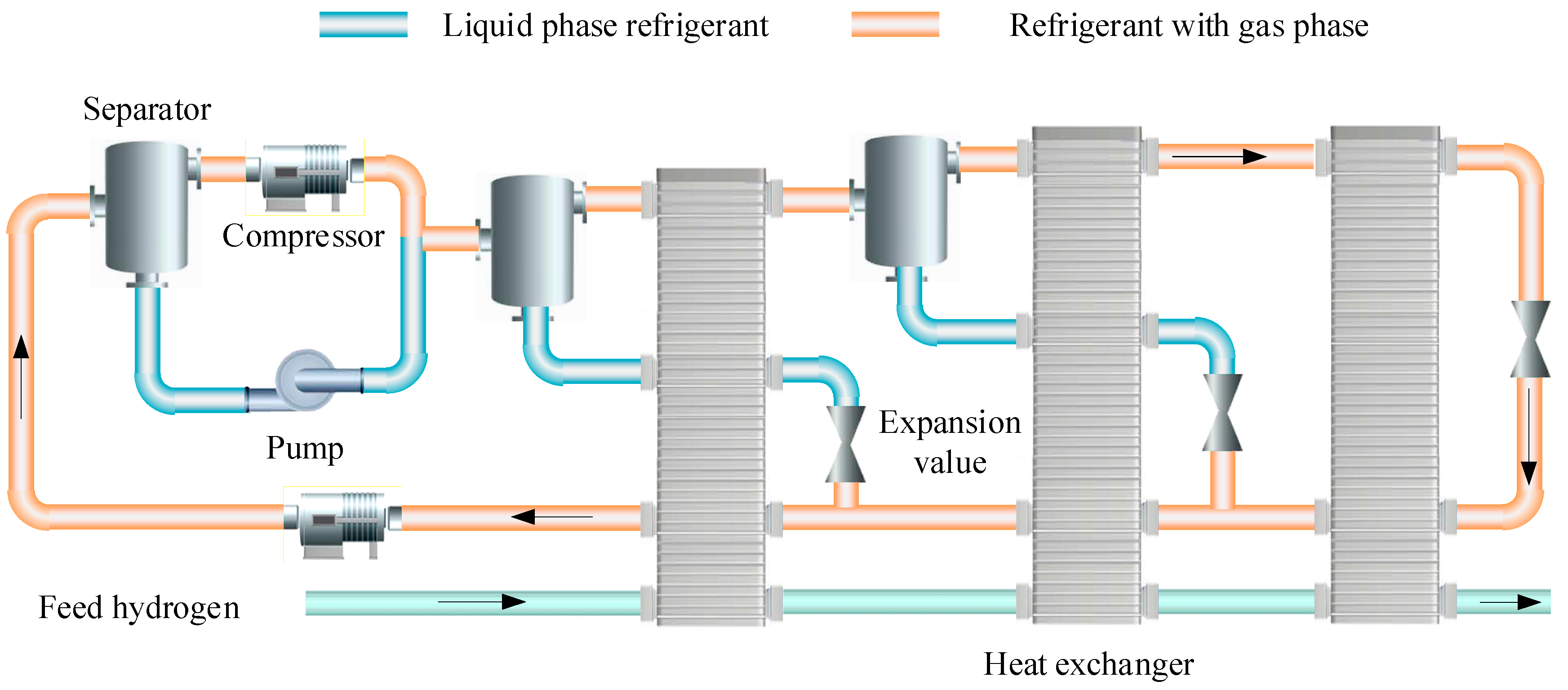
2.2.2. Mixed Refrigerant Cycle
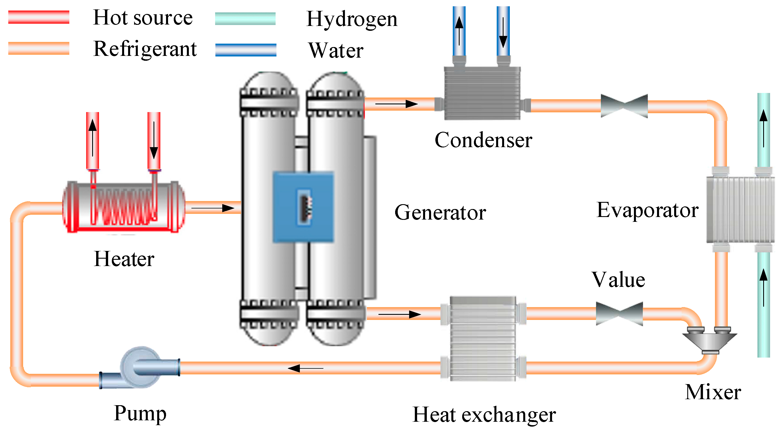
2.2.3. Absorption Refrigeration Cycle
3. Hydrogen Cryo-Cooling Process
3.1. Linde-Hampson Cycle
3.2. Claude Cycle
3.3. Joule-Brayton Refrigeration Cycle
3.4. Emerging Refrigeration Technologies
4. Ortho- and Para-Hydrogen Conversion
4.1. Isothermal Conversion
4.2. Adiabatic Conversion
4.3. Continuous Conversion
5. Summary and Conclusions
- The choice of a future hydrogen pre-cooling process depends on the availability of a stable cold source. LN2 from air separation units and LNG from LNG-receiving stations are the best pre-coolants for hydrogen pre-cooling. Among them, the supply of LN2 is limited, while the application of LNG is worth anticipating. The co-production of natural gas and LH2 is an important future direction for large-scale hydrogen liquefaction plants. Strategies for efficient utilization of LNG cold energy when used for hydrogen pre-cooling can be further investigated. For the absence of a cold source, the MRC is almost the only option for hydrogen pre-cooling. The components of mixed refrigerant must be simplified to ensure stable operation of the MRC. New refrigerants can be explored as replacements for existing mixed refrigeration options.
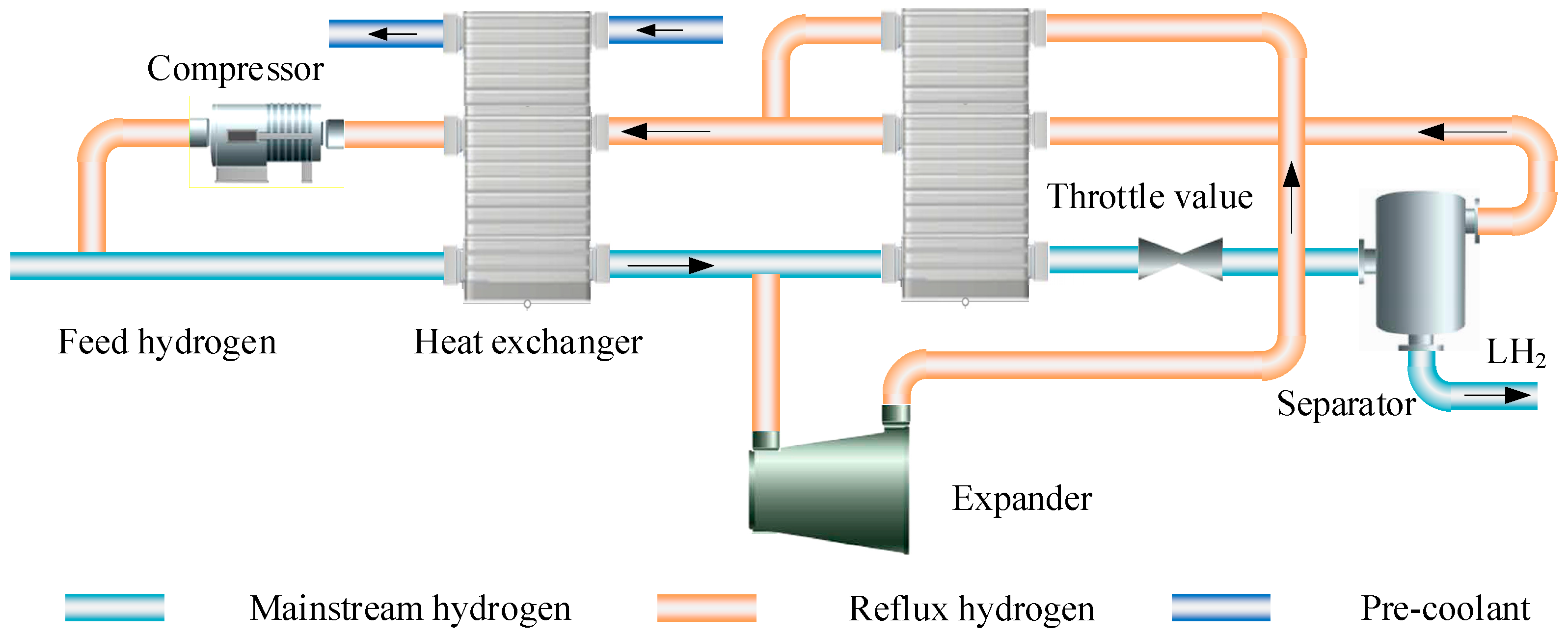
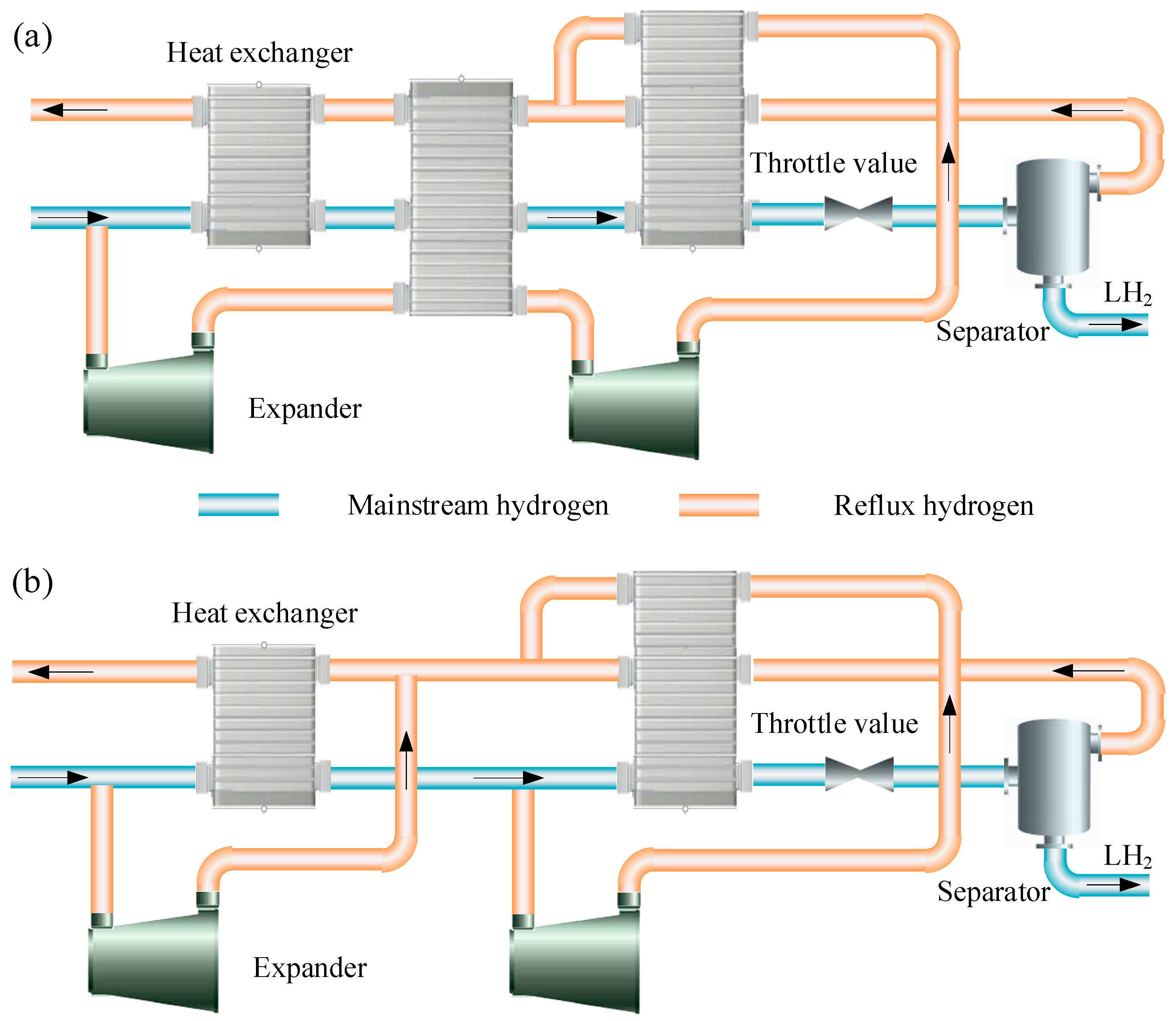
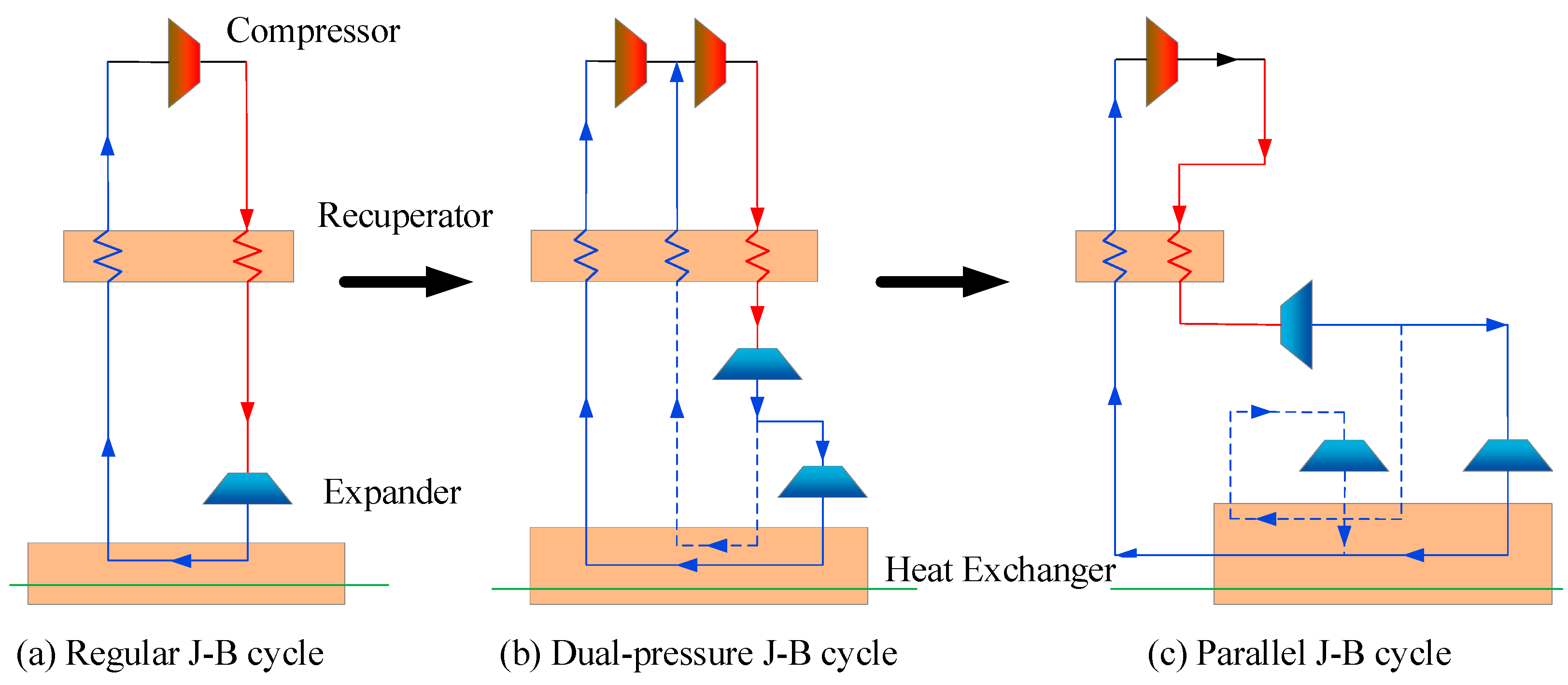
- The Claude cycle and the cascaded J-B refrigeration cycles are the dominant schemes used for hydrogen cryo-cooling. In large-scale hydrogen liquefaction systems, researchers prefer the Claude cycle. The active hydrogen liquefaction plant at Leuna provides good experience. An appropriate flash hydrogen processing method is adopted to achieve 100% hydrogen liquefaction. Thus, the injector may become a central component in future Claude cycles. For small and medium scale hydrogen liquefaction systems, the cascaded J-B refrigeration cycles are more accepted. Whether for the Claude cycle or the cascaded J-B refrigeration cycles, the heat exchange efficiency between hydrogen and refrigerant can be improved by adjusting the number of cascade cycles and the refrigeration temperatures of the individual cycles. Considerable research remains to be performed in this area.
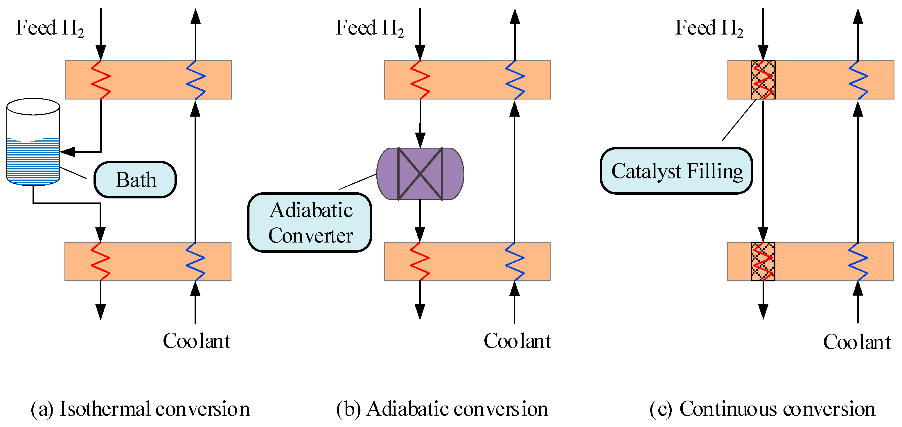
- The continuous conversion of OPH is the only option in the commercial production of LH2. The other two conversion modes do not meet the requirement for low energy consumption. From the available literature, the continuous conversion of OPH is in the stage of attack of key equipment. Recently, few studies have been reported for experimental testing of OPH conversion. This leads to low predictability and accuracy of kinetic modeling of the continuous conversion of OPH based on the available experimental data. Therefore, the center of future research should be placed on simulations and experiments related to OPH conversion.
Author Contributions
Funding
Data Availability Statement
Conflicts of Interest
References
- Orr, F.M., Jr. CO2 capture and storage: Are we ready? Energy Environ. Sci. 2009, 2, 449–458. [Google Scholar] [CrossRef]
- Durbin, D.J.; Malardier-Jugroot, C. Review of hydrogen storage techniques for on board vehicle applications. Int. J. Hydrogen Energy 2013, 38, 14595–14617. [Google Scholar] [CrossRef]
- Liu, W.; Wan, Y.M.; Xiong, Y.L.; Gao, P.B. Green hydrogen standard in China: Standard and evaluation of low-carbon hydrogen, clean hydrogen, and renewable hydrogen. Int. J. Hydrogen Energy 2022, 47, 24584–24591. [Google Scholar] [CrossRef]
- Verma, S.C.; Thakur, M.; Bhardwaj, S. Climate change and horticulture crop production. Int. J. Econ. Plants 2015, 2, 70–78. [Google Scholar]
- Morales-Ospino, R.; Celzard, A.; Fierro, V. Strategies to recover and minimize boil-off losses during liquid hydrogen storage. Renew. Sust. Energy Rev. 2023, 182, 113360. [Google Scholar] [CrossRef]
- Karakaya, E.; Nuur, C.; Assbring, L. Potential transitions in the iron and steel industry in Sweden: Towards a hydrogen-based future? J. Clean. Prod. 2018, 195, 651–663. [Google Scholar] [CrossRef]
- Naquash, A.; Riaz, A.; Qyyum, M.A.; Aziz, M.; Assareh, E.; Lee, M. Liquid hydrogen storage and regasification process integrated with LNG, NGL, and liquid helium production. Renew. Energy 2023, 213, 165–175. [Google Scholar] [CrossRef]
- AlHumaidan, F.S.; Halabi, M.A.; Rana, M.S.; Vinoba, M. Blue hydrogen: Current status and future technologies. Energy Convers. Manag. 2023, 283, 116840. [Google Scholar] [CrossRef]
- Wijayanta, A.T.; Oda, T.; Purnomo, C.W.; Kashiwagi, T.; Aziz, M. Liquid hydrogen, methylcyclohexane, and ammonia as potential hydrogen storage: Comparison review. Int. J. Hydrogen Energy 2019, 44, 15026–15044. [Google Scholar] [CrossRef]
- Koneczna, R.; Cader, J. Hydrogen in the strategies of the European Union member states. Gospod. Surowcami. Miner. 2021, 37, 53–74. [Google Scholar]
- Ghorbani, B.; Zendehboudi, S.; Saady, N.M.C.; Duan, X.; Albayati, T.M. Strategies to improve the performance of hydrogen storage systems by liquefaction methods: A comprehensive review. ACS Omega 2023, 8, 18358–18399. [Google Scholar] [CrossRef]
- Ghorbani, B.; Zendehboudi, S.; Saady, N.C.; Dusseault, M.B. Hydrogen storage in North America: Status, prospects, and challenges. J. Environ. Chem. Eng. 2023, 11, 109957. [Google Scholar] [CrossRef]
- Zhou, L. Progress and problems in hydrogen storage methods. Renew. Sust. Energy Rev. 2005, 9, 395–408. [Google Scholar] [CrossRef]
- Muthukumar, P.; Kumar, A.; Afzal, M.; Bhogilla, S.; Sharma, P.; Parida, A.; Jana, S.; Kumar, E.A.; Pai, R.K.; Jain, I. Review on large-scale hydrogen storage systems for better sustainability. Int. J. Hydrogen Energy 2023, 48, 33223–33259. [Google Scholar] [CrossRef]
- Muthukumar, P.; Kumar, A.; Afzal, M.; Bhogilla, S.; Sharma, P.; Parida, A.; Jana, S.; Kumar, E.A.; Pai, R.K.; Jain, I. Green hydrogen: Pathways, roadmap, and role in achieving sustainable development goals. Process Saf. Environ. 2023, 177, 664–687. [Google Scholar]
- Leng, Y.; Zhang, S.; Wang, X.; Pu, L.; Xu, P. Comparative study on thermodynamic performance of liquid hydrogen storage insulation system incorporating vapor-cooled shield with para–ortho hydrogen conversion by one-dimensional and quasi-two-dimensional model. Energy Convers. Manag. 2024, 321, 119068. [Google Scholar] [CrossRef]
- Gurz, M.; Baltacioglu, E.; Hames, Y.; Kaya, K. The meeting of hydrogen and automotive: A review. Int. J. Hydrogen Energy 2017, 42, 23334–23346. [Google Scholar] [CrossRef]
- Al Ghafri, S.Z.; Munro, S.; Cardella, U.; Funke, T.; Notardonato, W.; Trusler, J.P.M.; Leachman, J.; Span, R.; Kamiya, S.; Pearce, G.; et al. Hydrogen liquefaction: A review of the fundamental physics, engineering practice and future opportunities. Energy Environ. Sci. 2022, 15, 2690. [Google Scholar] [CrossRef]
- Andersson, J.; Gronkvist, S. Large-scale storage of hydrogen. Int. J. Hydrogen Energy 2019, 44, 11901–11919. [Google Scholar] [CrossRef]
- Yang, J.; Li, Y.Z.; Tan, H.B. Study on performance comparison of two hydrogen liquefaction processes based on the Claude cycle and the Brayton refrigeration cycle. Processes 2023, 11, 932. [Google Scholar] [CrossRef]
- Stroman, R.O.; Schuette, M.W.; Swider-Lyons, K.; Rodgers, J.A.; Edwards, D.J. Liquid hydrogen fuel system design and demonstration in a small long endurance air vehicle. Int. J. Hydrogen Energy 2014, 39, 11279–11290. [Google Scholar] [CrossRef]
- Sharma, S.; Ghoshal, S.K. Hydrogen the future transportation fuel: From production to applications. Renew. Sust. Energy Rev. 2015, 43, 1151–1158. [Google Scholar] [CrossRef]
- El-Osta, W.; Zeghlam, J. Hydrogen as a fuel for the transportation sector: Possibilities and views for future applications in Libya. Appl. Energy 2000, 65, 165–171. [Google Scholar] [CrossRef]
- Aasadnia, M.; Mehrpooya, M. Large-scale liquid hydrogen production methods and approaches: A review. Appl. Energy 2018, 212, 57–83. [Google Scholar] [CrossRef]
- Dewar, J. Liquid hydrogen. Science 1898, 8, 3–6. [Google Scholar] [CrossRef]
- Barron, R.F. Cryogenic Systems; Oxford University Press: Oxford, UK, 1966. [Google Scholar]
- Wayne Lawrence, S. Analysis of a Supercritical Hydrogen Liquefaction Cycle. Master’s Thesis, Massachusetts Institute of Technology, Cambridge, MA, USA, 2008. [Google Scholar]
- Krasae-in, S.; Stang, J.H.; Neksa, P. Development of large-scale hydrogen liquefaction processes from 1898 to 2009. Int. J. Hydrogen Energy 2010, 35, 4524–4533. [Google Scholar] [CrossRef]
- Drnevich, R. Hydrogen delivery—Liquefaction & compression. In Proceedings of the Praxair, Strategic Initiatives for Hydrogen Delivery Workshop, Danbury, CT, USA, 7 May 2003. [Google Scholar]
- Aziz, M. Liquid hydrogen: A review on liquefaction, storage, transportation, and safety. Energies 2021, 14, 5917. [Google Scholar] [CrossRef]
- Bracha, M.; Lorenz, G.A.; Wanner, M. Large-scale hydrogen liquefaction in Germany. Int. J. Hydrogen Energy 1994, 19, 53–59. [Google Scholar] [CrossRef]
- Kuendig, A.; Loehlein, K.; Kramer, G.J.; Huijsmans, J. Large scale hydrogen liquefaction in combination with LNG regasification. In Proceedings of the 16th World Hydrogen Energy Conference, Lyon, France, 13–16 June 2006. [Google Scholar]
- Zhang, T.; Uratani, J.; Huang, Y.; Xu, L.; Griffiths, S.; Ding, Y. Hydrogen liquefaction and storage: Recent progress and perspectives. Renew. Sust. Energy Rev. 2023, 176, 113204. [Google Scholar] [CrossRef]
- Nakano, A.; Maeda, T.; Ito, H.; Masuda, M.; Kawakami, Y.; Kato, A.; Tange, M.; Takahashi, T.; Matsuo, M. Small-scale hydrogen liquefaction with a two-stage Gifford-McMahon cycle refrigerator. Int. J. Hydrogen Energy 2010, 35, 9088–9094. [Google Scholar] [CrossRef]
- Garceau, N.M.; Baik, J.H.; Lim, C.M.; Kim, S.Y.; Oh, I.-H.; Karng, S.W. Development of a small-scale hydrogen liquefaction system. Int. J. Hydrogen Energy 2015, 40, 11872–11878. [Google Scholar] [CrossRef]
- Xie, F.S.; Xia, S.Q.; Zhu, Y.H.; Ma, Y.; Li, Y.Z. Experimental study on small-scale hydrogen liquefaction of 0.5 L/h. Int. J. Hydrogen Energy 2022, 47, 38258–38270. [Google Scholar] [CrossRef]
- Ha, D.W.; Noh, H.W.; Seo, Y.M.; Koo, T.H.; Ko, R.K. Development of a condensing-type hydrogen liquefaction system for improving cooling efficiency and long-term storage. Int. J. Hydrogen Energy 2024, 49, 1558–1571. [Google Scholar] [CrossRef]
- Bi, Y.J.; Xu, Y.F.; Ju, Y.L. Experimental investigation and simulation on a small-scale open hydrogen liquefaction system with stepwise cooling. Int. J. Hydrogen Energy 2024, 80, 370–380. [Google Scholar] [CrossRef]
- Bian, J.; Yang, J.; Li, Y.; Chen, Z.; Liang, F.; Cao, X. Thermodynamic and economic analysis of a novel hydrogen liquefaction process with LNG precooling and dual-pressure Brayton cycle. Energy Convers. Manag. 2021, 250, 114904. [Google Scholar] [CrossRef]
- Zhang, Q.; Huang, X.; Zhang, S.; Shen, Y.; Xu, H.; Sun, M.; Wang, Q.; Zhao, L. Energy-exergy evaluation of liquefied hydrogen production system based on steam methane reforming and LNG revaporization. Case Stud. Therm. Eng. 2023, 49, 103363. [Google Scholar] [CrossRef]
- Zhou, K.; Chen, L.; Li, S.; Zhao, K.; Zhang, Z.; Chen, S.; Hou, Y. Comparative analysis of energy losses in hydrogen and helium turbo-expanders for hydrogen liquefiers. Appl. Therm. Eng. 2023, 227, 120322. [Google Scholar] [CrossRef]
- Azizabadi, H.R.; Ziabasharhagh, M.; Mafi, M. Introducing a proper hydrogen liquefaction concept for using wasted heat of thermal power plants-case study: Parand gas power plant. Chinese J. Chem. Eng. 2021, 40, 187–196. [Google Scholar] [CrossRef]
- Ghorbani, B.; Mehrpooya, M.; Aasadnia, M.; Niasar, M.S. Hydrogen liquefaction process using solar energy and organic Rankine cycle power system. J. Clean. Prod. 2019, 235, 1465–1482. [Google Scholar] [CrossRef]
- Sadaghiani, M.S.; Mehrpooya, M. Introducing and energy analysis of a novel cryogenic hydrogen liquefaction process configuration. Int. J. Hydrogen Energy 2017, 42, 6033–6050. [Google Scholar] [CrossRef]
- Stolzenburga, K.; Berstad, D.; Deckerc, L.; Elliottd, A.; Haberstroh, C.; Hattof, C.; Klaus, M.; Mortimer, N.D.; Mubbala, R.; Mwabonje, O.; et al. Efficient liquefaction of hydrogen: Results of the IDEALHY Project. In Proceedings of the Energie—Symposium, Stralsund, Germany, 7–9 November 2013. [Google Scholar]
- Qyyum, M.A.; Riaz, A.; Naquash, A.; Haider, J.; Qadeer, K.; Nawaz, A.; Lee, H.; Lee, M. 100% saturated liquid hydrogen production: Mixed-refrigerant cascaded process with two-stage ortho-to-para hydrogen conversion. Energy Convers. Manag. 2021, 246, 114659. [Google Scholar] [CrossRef]
- Ansarinasab, H.; Fatimah, M.; Khojasteh-Salkuyeh, Y. Conceptual design of two novel hydrogen liquefaction processes using a multistage active magnetic refrigeration system. Appl. Therm. Eng. 2023, 230, 120771. [Google Scholar] [CrossRef]
- Riaz, A.; Qyyum, M.A.; Min, S.; Lee, S. Performance improvement potential of harnessing LNG regasification for hydrogen liquefaction process: Energy and exergy perspectives. Appl. Energy 2021, 301, 117471. [Google Scholar] [CrossRef]
- Cardella, U.; Decker, L.; Sundberg, J.; Klein, H. Process optimization for large-scale hydrogen liquefaction. Int. J. Hydrogen Energy 2017, 42, 12339–12354. [Google Scholar] [CrossRef]
- Khodaparast, S.H.; Zare, V.; Mohammadkhani, F. Geothermal assisted hydrogen liquefaction systems integrated with liquid nitrogen precooling; Thermoeconomic comparison of Claude and reverse Brayton cycle for liquid nitrogen supply. Process Saf. Environ. 2023, 171, 28–37. [Google Scholar] [CrossRef]
- Li, J.; Zhang, Z.; Zhang, S.; Shi, F.; Nie, Y.; Xu, L.; Ma, X. Life cycle assessment of liquefied natural gas production from coke oven gas in China. J. Clean. Prod. 2021, 329, 129609. [Google Scholar] [CrossRef]
- Chen, S.; Shen, Y.; Qiu, C.; Tao, X.; Wan, A.; Zhang, Z.; Gan, Z. Multi-objective optimization of a hydrogen liquefaction process coupled with mixed refrigerant cycle and steam methane reforming. Int. J. Hydrogen Energy 2024, 58, 797–805. [Google Scholar] [CrossRef]
- Chang, H.M.; Kim, B.H.; Choi, B. Hydrogen liquefaction process with Brayton refrigeration cycle to utilize the cold energy of LNG. Cryogenics 2020, 108, 103093. [Google Scholar] [CrossRef]
- Qiao, Y.; Jiang, W.; Li, Y.; Dong, X.; Yang, F. Design and analysis of steam methane reforming hydrogen liquefaction and waste heat recovery system based on liquefied natural gas cold energy. Energy 2024, 302, 131792. [Google Scholar] [CrossRef]
- Zarsazi, H.; Sadeghi, S.; Moghimi, M. Investigation of a novel hybrid LNG waste heat-/wind-driven hydrogen liquefaction system: Exergoeconomic analysis and multi-criteria optimization. J. Therm. Anal. Calorim. 2023, 148, 8127–8143. [Google Scholar] [CrossRef]
- Yang, J.; Li, Y.Z.; Tan, H.B.; Bian, J.; Cao, X.W. Optimization and analysis of a hydrogen liquefaction process integrated with the liquefied natural gas gasification and organic Rankine cycle. J. Energy Storage 2023, 59, 106490. [Google Scholar] [CrossRef]
- Hai, T.; Alhaider, M.M.; Ghodratallah, P.; Singh, P.K.; Alhomayani, F.M.; Rajab, H. Techno-economic-environmental study and artificial intelligence-assisted optimization of a multigeneration power plant based on a gas turbine cycle along with a hydrogen liquefaction unit. Appl. Therm. Eng. 2024, 237, 121660. [Google Scholar] [CrossRef]
- Mehrenjani, J.R.; Gharehghani, A.; Sangesaraki, A.G. Machine learning optimization of a novel geothermal driven system with LNG heat sink for hydrogen production and liquefaction. Energy Convers. Manag. 2022, 254, 115266. [Google Scholar] [CrossRef]
- Bi, Y.J.; Ju, Y.L. Design and analysis of an efficient hydrogen liquefaction process based on helium reverse Brayton cycle integrating with steam methane reforming and liquefied natural gas cold energy utilization. Energy 2022, 252, 124047. [Google Scholar] [CrossRef]
- Cho, S.; Park, J.; Noh, W.; Lee, I.; Moon, I. Developed hydrogen liquefaction process using liquefied natural gas cold energy: Design, energy optimization, and techno-economic feasibility. Int. J. Energy Res. 2021, 45, 14745–14760. [Google Scholar] [CrossRef]
- Li, K.Y.; Lei, Z.H.; Wang, Z.L.; Li, S.L.; Liu, G.L. Thermodynamic analysis and optimization of hydrogen liquefaction system with binary refrigerant precooling cycle. J. Clean. Prod. 2024, 467, 142965. [Google Scholar] [CrossRef]
- Ding, X.; Duan, L.; Zheng, N.; Desideri, U.; Zhou, Y.; Wang, Q.; Wang, Y.; Jiao, W. A systematic review on liquid air energy storage system. Renew. Sust. Energy Rev. 2025, 210, 115164. [Google Scholar] [CrossRef]
- Yang, Y.; Tong, L.; Liu, Y.; Guo, W.; Wang, L.; Qiu, Y.; Ding, Y. A novel integrated system of hydrogen liquefaction process and liquid air energy storage (LAES): Energy, exergy, and economic analysis. Energy Convers. Manag. 2023, 280, 116799. [Google Scholar] [CrossRef]
- Taghavi, M.; Salarian, H.; Ghorbani, B. Thermodynamic and exergy evaluation of a novel integrated hydrogen liquefaction structure using liquid air cold energy recovery, solid oxide fuel cell and photovoltaic panels. J. Clean. Prod. 2021, 320, 128821. [Google Scholar] [CrossRef]
- Naquash, A.; Qyyum, M.A.; Islam, M.; Sial, N.R.; Min, S.; Lee, S.; Lee, M. Performance enhancement of hydrogen liquefaction process via absorption refrigeration and organic Rankine cycle-assisted liquid air energy system. Energy Convers. Manag. 2022, 254, 115200. [Google Scholar] [CrossRef]
- Chen, X.; Yue, J.; Fu, L.; Zhang, M.; Tang, M.; Feng, J.; Shen, B. Green hydrogen production and liquefaction using offshore wind power, liquid air, and LNG cold energy. J. Clean. Prod. 2023, 423, 138653. [Google Scholar] [CrossRef]
- Radebaugh, R. Cryocoolers: The state of the art and recent developments. J. Phys. Condens. Matter 2009, 21, 164219. [Google Scholar] [CrossRef]
- Li, Q.; Machida, H.; Norinaga, K. Design and optimization of large-scale green liquid hydrogen production integrated with heat recovery and absorption precooling. Ind. Eng. Chem. Res. 2024, 63, 19063–19075. [Google Scholar] [CrossRef]
- Faramarzi, S.; Gharanli, S.; Mohammadi, M.R.; Rahimtabar, A.; Chamkha, A.J. Energy, exergy, and economic analysis of an innovative hydrogen liquefaction cycle integrated into an absorption refrigeration system and geothermal energy. Energy 2023, 282, 128891. [Google Scholar] [CrossRef]
- Yang, J.-H.; Yoon, Y.; Ryu, M.; An, S.-K.; Shin, J.; Lee, C.-J. Integrated hydrogen liquefaction process with steam methane reforming by using liquefied natural gas cooling system. Appl. Energy 2019, 255, 113840. [Google Scholar] [CrossRef]
- Bae, J.E.; Wilailak, S.; Yang, J.H.; Yun, D.Y.; Zahid, U. Multi-objective optimization of hydrogen liquefaction process integrated with liquefied natural gas system. Energy Convers. Manag. 2021, 231, 113835. [Google Scholar] [CrossRef]
- Asadnia, M.; Mehrpooya, M. A novel hydrogen liquefaction process configuration with combined mixed refrigerant systems. Int. J. Hydrogen Energy 2017, 42, 15564–15585. [Google Scholar] [CrossRef]
- Stang, J.; Neksa, P.; Brendeng, E. On the design of an efficient hydrogen liquefaction process. In Proceedings of the WHEC16: 16. World Hydrogen Energy Conference, Lyon, France, 13–16 June 2006. [Google Scholar]
- Krasae-in, S.; Bredesen, A.M.; Stang, J.H.; Neksa, P. Simulation and experiment of a hydrogen liquefaction test rig using a multi-component refrigerant refrigeration system. Int. J. Hydrogen Energy 2011, 36, 907–919. [Google Scholar] [CrossRef]
- Bian, J.; Zhang, X.; Zhang, R.; Cai, W.; Hua, Y.; Cao, X. Conceptual design and analysis of a new hydrogen liquefaction process based on heat pump systems. Appl. Energy 2024, 374, 124020. [Google Scholar] [CrossRef]
- Taghavi, M.; Lee, C.J. Development of novel hydrogen liquefaction structures based on waste heat recovery in diffusion-absorption refrigeration and power generation units. Energy Convers. Manag. 2024, 302, 118056. [Google Scholar] [CrossRef]
- Ghorbani, B.; Zendehboudi, S.; Moradi, M. Development of an integrated structure of hydrogen and oxygen liquefaction cycle using wind turbines, Kalina power generation cycle, and electrolyzer. Energy 2021, 221, 119653. [Google Scholar] [CrossRef]
- Xu, J.X.; Song, Z.; Chen, X.; Yang, Q. Design and optimization of high-density cryogenic supercritical hydrogen storage systems integrating with dual mixed refrigerant cycles. Energy 2024, 290, 130124. [Google Scholar] [CrossRef]
- Noh, W.; Park, S.; Kim, J.; Lee, I. Comparative design, thermodynamic and techno-economic analysis of utilizing liquefied natural gas cold energy for hydrogen liquefaction processes. Int. J. Energy Res. 2022, 46, 12926–12947. [Google Scholar] [CrossRef]
- Aasadnia, M.; Mehrpooya, M. Conceptual design and analysis of a novel process for hydrogen liquefaction assisted by absorption precooling system. J. Clean. Prod. 2018, 205, 565–588. [Google Scholar] [CrossRef]
- Krasae-in, S.; Stang, J.H.; Neksa, P. Simulation on a proposed large-scale liquid hydrogen plant using a multi-component refrigerant refrigeration system. Int. J. Hydrogen Energy 2010, 35, 12531–12544. [Google Scholar] [CrossRef]
- Luo, L.M.; Shen, J.B.; Chen, Y.P.; Wang, B.D. Study on a novel hydrogen liquification process applying mixed-refrigerant for pre-cooling and cryogenics. Int. J. Hydrogen Energy 2024, 68, 277–288. [Google Scholar] [CrossRef]
- Sleiti, A.K.; Al-Ammari, W.A. A novel dual-pressure single-mixed refrigerant cryogenic system for hydrogen precooling process: Optimization and thermoeconomic analysis. Int. J. Hydrogen Energy 2024, 85, 893–908. [Google Scholar] [CrossRef]
- Ansarinasab, H.; Mehrpooya, M.; Mohammadi, A. Advanced exergy and exergoeconomic analyses of a hydrogen liquefaction plant equipped with mixed refrigerant system. J. Clean. Prod. 2017, 144, 248–259. [Google Scholar] [CrossRef]
- Krasae-in, S. Optimal operation of a large-scale liquid hydrogen plant utilizing mixed fluid refrigeration system. Int. J. Hydrogen Energy 2014, 39, 7015–7029. [Google Scholar] [CrossRef]
- Ebrahimi, A.; Ghorbani, B.; Ziabasharhagh, M. Pinch and sensitivity analyses of hydrogen liquefaction process in a hybridized system of biomass gasification plant, and cryogenic air separation cycle. J. Clean. Prod. 2020, 258, 120548. [Google Scholar] [CrossRef]
- Faramarzi, S.; Khavari, A. An innovative mixed refrigerant hydrogen liquefaction cycle to store geothermal energy as liquid hydrogen. J. Energy Storage 2023, 72, 108008. [Google Scholar] [CrossRef]
- Jackson, S.; Brodal, E. Optimization of a mixed refrigerant based H2 liquefaction pre-cooling process and estimate of liquefaction performance with varying ambient temperature. Energies 2021, 14, 6090. [Google Scholar] [CrossRef]
- Equbal, S.; Khan, O.; Equbal, A.; Parvez, M.; Ahmad, S.; Yahya, Z.; Alhodaib, A.; Yadav, A.K.; Ağbulut, Ü. Comparative analysis of machine learning and artificial intelligence models for optimizing mixed refrigerant characteristics in a hydrogen pre-cooling storage system. J. Energy Storage 2024, 102, 114101. [Google Scholar] [CrossRef]
- Jouybari, A.K.; Ilinca, A.; Ghorbani, B.; Rooholamini, S. Thermodynamic and exergy evaluation of an innovative hydrogen liquefaction structure based on ejector-compression refrigeration unit, cascade multi-component refrigerant system, and Kalina power plant. Int. J. Hydrogen Energy 2022, 47, 26369–26393. [Google Scholar] [CrossRef]
- Ghorbani, B.; Manesh, M.H.K.; Ebrahimi, A. Exergy and pinch investigation of a novel configuration for the liquid hydrogen production by polymer electrolyte membrane electrolyzer and mixed refrigerant-absorption cooling cycles. Fuel 2023, 341, 127623. [Google Scholar] [CrossRef]
- Yamin, Z.; El-Shafay, A.; Saraswat, M.; Mahariq, I.; Alhomayani, F.M.; Rajab, H.; Almojil, S.F.; Almohana, A.I.; Sillanpää, M. Integrating solar-powered branched GAX cycle and claude cycle for producing liquid hydrogen: Comprehensive study using real data and optimization. Energy 2024, 312, 133496. [Google Scholar] [CrossRef]
- Cao, Y.; Dhahad, H.A.; Togun, H.; Aly, A.A.; Felemban, B.F.; El-Shafay, A.; Rashidi, S.; Farhang, B. Application, comparative study, and multi-objective optimization of a hydrogen liquefaction system utilizing either ORC or an absorption power cycle. Int. J. Hydrogen Energy 2022, 47, 26408–26421. [Google Scholar] [CrossRef]
- Faramarzi, S.; Esmat, P.; Karimi, E.; Abdollahi, S.A. Energy, exergy, economic, and sensitivity analyses of an enhanced liquid hydrogen production cycle within an innovative multi-generation system. J. Therm. Anal. Calorim. 2024, 149, 3513–3530. [Google Scholar] [CrossRef]
- Yilmaz, C.; Kaska, O. Performance analysis and optimization of a hydrogen liquefaction system assisted by geothermal absorption precooling refrigeration cycle. Int. J. Hydrogen Energy 2018, 43, 20203–20213. [Google Scholar] [CrossRef]
- Yilmaz, C. A case study: Exergoeconomic analysis and genetic algorithm optimization of performance of a hydrogen liquefaction cycle assisted by geothermal absorption precooling cycle. Renew. Energy 2018, 128, 68–80. [Google Scholar] [CrossRef]
- Zhang, S.; Li, K.; Liu, G. An efficient hydrogen liquefaction process integrated with a solar power tower and absorption precooling system. Clean. Technol. Environ. 2023, 25, 1015–1041. [Google Scholar] [CrossRef]
- Yan, F.; Geng, J.; Rong, G.; Sun, H.; Zhang, L.; Li, J. Optimization and analysis of an integrated liquefaction process for hydrogen and natural gas utilizing mixed refrigerant pre-cooling. Energies 2023, 16, 4239. [Google Scholar] [CrossRef]
- Aasadnia, M.; Mehrpooya, M.; Ansarinasab, H. A 3E evaluation on the interaction between environmental impacts and costs in a hydrogen liquefier combined with absorption refrigeration systems. Appl. Therm. Eng. 2019, 159, 113798. [Google Scholar] [CrossRef]
- Nandi, T.K.; Sarangi, S. Performance and optimization of hydrogen liquefaction cycles. Int. J. Hydrogen Energy 1993, 18, 131–139. [Google Scholar] [CrossRef]
- Winterbone, D.E.; Turan, A. Liquefaction of gases. Adv. Thermodyn. Eng. 2015, 423–445. [Google Scholar] [CrossRef]
- Panahi, A.H.; Gharehghani, A.; Ghandehariun, S.; Rosen, M.A. Techno-economic analysis and optimization of green hydrogen production and liquefaction with metal hydride storage. J. Clean. Prod. 2023, 423, 138783. [Google Scholar] [CrossRef]
- Assareh, E.; Agarwal, N.; Paul, M.C.; Ahmadi, P.; Ghodrat, M.; Lee, M. Investigation and development of a novel solar-biomass integrated energy system for clean electricity and liquid hydrogen production. Therm. Sci. Eng. Prog. 2023, 42, 101925. [Google Scholar] [CrossRef]
- Koc, M.; Yuksel, Y.E.; Qzturk, M. Thermodynamic assessment of a novel multigenerational power system for liquid hydrogen production. Int. J. Hydrogen Energy 2022, 47, 31806–31820. [Google Scholar] [CrossRef]
- Yuksel, Y.E.; Qzturk, M.; Dincer, I. Energy and exergy analyses of an integrated system using waste material gasification for hydrogen production and liquefaction. Energy Convers. Manag. 2019, 185, 718–729. [Google Scholar] [CrossRef]
- Kwon, H.; Park, J.; Koo, B. 4E analysis for a novel cryogenic hydrogen liquefaction process using various refrigerants: Energy, exergy, economic, and environment. J. Clean. Prod. 2024, 469, 143146. [Google Scholar] [CrossRef]
- Yang, J.; Li, Y.Z.; Li, C.; Tan, H.B. Hydrogen pressure-based comparative and applicability analysis of different innovative Claude cycles for large-scale hydrogen liquefaction. Energy 2024, 305, 132291. [Google Scholar] [CrossRef]
- Im, J.; Gye, H.-R.; Wilailak, S.; Yoon, H.-J.; Kim, Y.; Kim, H.; Lee, C.-J. Hydrogen liquefaction process using carbon dioxide as a pre-coolant for carbon capture and utilization. Energy 2024, 307, 132698. [Google Scholar] [CrossRef]
- Seyam, S.; Dincer, I.; Agelin-Chaab, M. Development of a clean power plant integrated with a solar farm for a sustainable community. Energy Convers. Manag. 2020, 225, 113434. [Google Scholar] [CrossRef]
- Kim, H.S.; Cho, C.H. Comparative analysis of liquefied natural gas cold energy scenarios for hydrogen liquefaction: 3E (Energy, economic, and environmental) analysis. Int. J. Hydrogen Energy 2023, 48, 31267–31279. [Google Scholar] [CrossRef]
- Berstad, D.; Skaugen, G.; Wilhelmsen, Ø. Dissecting the exergy balance of a hydrogen liquefier: Analysis of a scaled-up claude hydrogen liquefier with mixed refrigerant pre-cooling. Int. J. Hydrogen Energy 2021, 46, 8014–8029. [Google Scholar] [CrossRef]
- Cammarata, G.; Fichera, A.; Guglielmino, D. Optimization of a liquefaction plant using genetic algorithms. Appl. Energy 2001, 68, 19–29. [Google Scholar] [CrossRef]
- Yang, J.; Li, Y.Z.; Tan, H.B. Integrated hydrogen liquefaction process with a dual-pressure organic Rankine cycle-assisted LNG regasification system: Design, comparison, and analysis. Appl. Energy 2023, 347, 121372. [Google Scholar] [CrossRef]
- Geng, J.L.; Sun, H. A novel integrated hydrogen and natural gas liquefaction process utilizing a modified double mixed refrigerant process pre-cooling system. Appl. Therm. Eng. 2023, 224, 120085. [Google Scholar] [CrossRef]
- Yu, S.; Wang, Z.; Qiu, G.; Che, X.; Chen, J.; Li, Q.; Cai, W. Optimization and analysis of a novel hydrogen liquefaction coupled system with dual path hydrogen refrigeration cycle and the closed nitrogen cycle pre-cooling. J. Clean. Prod. 2024, 470, 143281. [Google Scholar] [CrossRef]
- Geng, J.L.; Sun, H. Optimization and analysis of a hydrogen liquefaction process: Energy, exergy, economic, and uncertainty quantification analysis. Energy 2023, 262, 125410. [Google Scholar] [CrossRef]
- Valenti, G.; Macchi, E. Proposal of an innovative, high-efficiency, large-scale hydrogen liquefier. Int. J. Hydrogen Energy 2008, 33, 3116–3121. [Google Scholar] [CrossRef]
- Faramarzi, S.; Nainiyan, S.M.M.; Mafi, M.; Ghasemiasl, R. A novel hydrogen liquefaction process based on LNG cold energy and mixed refrigerant cycle. Int. J. Refrig. 2021, 131, 263–274. [Google Scholar] [CrossRef]
- Ghorbani, B.; Ebrahimi, A.; Rooholamini, S.; Ziabasharhagh, M. Integrated Fischer-Tropsch synthesis process with hydrogen liquefaction cycle. J. Clean. Prod. 2021, 283, 124592. [Google Scholar] [CrossRef]
- Yang, J.; Li, Y.Z.; Tan, H.B. An energy-saving hydrogen liquefaction process with efficient utilization of liquefied natural gas cold energy. Int. J. Hydrogen Energy 2024, 49, 1482–1496. [Google Scholar] [CrossRef]
- Gao, Z.C.; Gou, W.G.; Chen, H.Q.; Li, C.M.; Zhang, Y.H. Design and performance comparison of large-scale hydrogen liquefaction processes based on mixed refrigerant cycle. Int. J. Hydrogen Energy Accept 2025, 107, 438–451. [Google Scholar] [CrossRef]
- Zou, A.H.; Zeng, Y.P.; Luo, E.C. New generation hydrogen liquefaction technology by transonic two-phase expander. Energy 2023, 272, 127150. [Google Scholar] [CrossRef]
- Tang, X.; Sepehri-Amin, H.; Terada, N.; Martin-Cid, A.; Kurniawan, I.; Kobayashi, S.; Kotani, Y.; Takeya, H.; Lai, J.; Matsushita, Y.; et al. Magnetic refrigeration material operating at a full temperature range required for hydrogen liquefaction. Nat. Commun. 2022, 13, 1817. [Google Scholar] [CrossRef] [PubMed]
- Choi, J. Liquid Hydrogen Properties; Kaeri/TR-2723: Daejon, Republic of Korea, 2004. [Google Scholar]
- Baker, C.R.; Shaner, R.L. A study of the efficiency of hydrogen liquefaction. Int. J. Hydrogen Energy 1978, 3, 321–334. [Google Scholar] [CrossRef]
- Teng, J.; Wang, K.; Zhu, S.; Bao, S.; Zhi, X.; Zhang, X.; Qiu, L. Comparative study on thermodynamic performance of hydrogen liquefaction processes with various ortho-para hydrogen conversion methods. Energy 2023, 271, 127016. [Google Scholar] [CrossRef]
- Kuz’menko, I.F.; Morkovkin, I.M.; Gurov, E.I. Concept of building medium-capacity hydrogen liquefiers with helium refrigeration cycle. Chem. Petrol. Eng. 2004, 40, 94–98. [Google Scholar] [CrossRef]
- Aspen Technology. Aspen HYSYS Unit Operations Reference Guide Version Number: V10; Aspen Technology: Bedford, MA, USA, 2017; p. 1193. [Google Scholar]
- Sun, H.; Geng, J.; Wang, C.; Rong, G.; Gao, X.; Xu, J.; Yang, D. Optimization of a hydrogen liquefaction process utilizing mixed refrigeration considering stages of ortho-para hydrogen conversion. Int. J. Hydrogen Energy 2022, 47, 17271–17284. [Google Scholar] [CrossRef]
- Xu, Y.F.; Bi, Y.J.; Ju, Y.L. Quantitative analysis of the effects of catalytic ortho-para hydrogen conversion on the hydrogen liquefaction process. In Proceedings of the 10th Hydrogen Technology Convention, Volume 2, WHTC 2023, Foshan, China, 22–26 May 2023; Springer: Singapore, 2024; Volume 394. [Google Scholar]
- Hunter, J.B.; Mcguire, G. Method. and Apparatus for Catalytic Heat Exchange. U.S. Patent 4214867, 29 July 1980. [Google Scholar]
- Xu, P.; Wen, J.; Li, K.; Wang, S.M.; Li, Y.Z. Review of the continuous catalytic ortho-para hydrogen conversion technology for hydrogen liquefaction. Int. J. Hydrogen Energy 2024, 62, 473–487. [Google Scholar] [CrossRef]
- Wen, J.; Xie, H.L.; Zhao, X.; Li, K. Energy-efficient hydrogen liquefaction process with ortho-para conversion and boil-off gas recovery. Chem Eng. Technol. 2024, 47, e202400150. [Google Scholar] [CrossRef]
- Donaubauer, P.J.; Cardella, U.; Decker, L.; Klein, H. Kinetics and heat exchanger design for catalytic ortho-para hydrogen conversion during liquefaction. Chem. Eng. Technol. 2019, 42, 669–679. [Google Scholar] [CrossRef]
- Park, J.; Lim, H.; Rhee, G.; Karng, S.W. Catalyst filled heat exchanger for hydrogen liquefaction. Int. J. Heat. Mass. Tran. 2021, 170, 121007. [Google Scholar] [CrossRef]
- Fan, X.; Li, Y.; Sun, C.; Liu, L.; Yang, H. Experimental and numerical study on tube-side flow and heat transfer characteristics of superheated vapor flow in catalyst-filled LH2 spiral wound heat exchanger. Int. J. Hydrogen Energy 2022, 47, 36582–36592. [Google Scholar] [CrossRef]
- Xu, P.; Wen, J.; Wang, S.; Chen, Q.; Li, Y. Numerical model improvement of a plate-fin heat exchanger filled with catalyst for hydrogen liquefaction. Int. J. Hydrogen Energy 2023, 48, 31671–31684. [Google Scholar] [CrossRef]
- Xu, P.; Wen, J.; Li, K.; Wang, S.; Chen, Q.; Li, Y. Structural improvement of catalyst filled channel of continuous ortho-para hydrogen conversion technology. Therm. Sci. Eng. Prog. 2023, 43, 101974. [Google Scholar] [CrossRef]
- Skaugen, G.; Berstad, D.; Wilhelmsen, O. Comparing exergy losses and evaluating the potential of catalyst-filled plate-fin and spiral-wound heat exchangers in a largescale Claude hydrogen liquefaction process. Int. J. Hydrogen Energy 2020, 45, 6663–6679. [Google Scholar] [CrossRef]
- Zhu, S.; Teng, J.; Zhi, X.; Bao, S.; Qiu, L.; Wang, K. Numerical study on comprehensive performance of flow and heat transfer coupled with ortho-para hydrogen conversion. Int. J. Heat. Mass. Tran. 2023, 201, 123653. [Google Scholar] [CrossRef]
- Teng, J.; Zhu, S.; Wei, X.; Qi, Y.; Zhi, X.; Bao, S.; Qiu, L.; Wang, K. Roles of catalysts’ porous media feature and catalytic conversion effect on the performance of plate-fin heat exchangers in hydrogen liquefaction. Int. J. Heat. Mass. Tran. 2024, 218, 124761. [Google Scholar] [CrossRef]


| Ref. | Compressed Gas (35 MPa) | Compressed Gas (70 MPa) | Liquid Hydrogen | Methanol | NH3 |
|---|---|---|---|---|---|
| Volumetric density (kg/m3) | 23.3 | 39.2 | 70.9 | 786 | 682 |
| Volumetric hydrogen density (kgH2/m3) | 23.3 | 39.2 | 70.9 | 99 | 121 |
| Mass hydrogen density (wt%) | 100 | 100 | 100 | 12.5 | 17.8 |
| Specific energy consumption (kWh/kg) | 2.8 | 5.6 | 6.4–15.0 | 17.6–30.4 | 19.1–30.0 |
| Levelized cost of end product ($/kg) | 0.22–0.28 | 2.83 | 0.5–3 | 2–4.17 | 1–2.17 |
| Ref. | H2 | N2 | CH4 | C2H6 | C3H8 | n-C4H10 | i-C4H10 | C5H12 | R14 | Acetone | C2H4 | NH3 | SEC 1 | EXE 2 |
|---|---|---|---|---|---|---|---|---|---|---|---|---|---|---|
| Bian et al. [75] | 0.013 | 0.136 | 0.136 | 0.162 | 0.064 | 0.017 | 0.017 | 0.189 | 0.152 | 0.114 | - 3 | - | 5.633 | 53.15 |
| Azizabadi et al. [43] | 0.1 | 0.15 | 0.18 | 0.1 | 0.16 | - | - | 0.08 | 0.08 | - | 0.15 | - | 4.54 | - |
| Taghavi et al. [76] | 0.01 | 0.16 | 0.17 | 0.07 | 0.18 | 0.02 | - | 0.15 | 0.08 | - | 0.16 | - | 4.32 | 53.35 |
| Chorbani et al. [77] | 0.04 | 0.18 | 0.24 | 0.28 | - | 0.26 | - | - | - | - | - | - | 5.462 | 58.73 |
| Xu et al. [78] | - | 0.11 | 0.222 | 0.115 | 0.166 | - | - | 0.238 | - | - | 0.149 | - | 6.422 | 52.66 |
| - | 0.065 | 0.16 | 0.028 | 0.225 | - | - | 0.297 | - | - | 0.225 | - | 6.872 | 49.24 | |
| Noh et al. [79] | 0.01 | 0.16 | 0.17 | 0.07 | 0.18 | 0.02 | - | 0.15 | 0.08 | - | 0.16 | - | 5.613 | - |
| Asadnia et al. [72] | 0.0002 | 0.0642 | 0.1021 | 0.1925 | 0.0532 | 0.0235 | 0.0243 | 0.2982 | 0.0986 | 0.1273 | - | 0.0158 | 7.69 | - |
| Asadnia et al. [80] | 0.0002 | 0.0642 | 0.1021 | 0.1925 | 0.0532 | 0.0235 | 0.0243 | 0.2982 | 0.0986 | 0.1273 | - | 0.0158 | 6.47 | - |
| Krasae-in et al. [81] | 0.012 | 0.136 | 0.136 | 0.162 | 0.064 | 0.017 | 0.017 | 0.189 | 0.152 | 0.114 | - | - | 5.35 | 54.02 |
| Luo et al. [82] | 0.0143 | 0.0712 | 0.1772 | 0.149 | 0.0479 | 0.0209 | 0.0202 | 0.2736 | 0.1208 | 0.0913 | - | 0.1208 | 6.15 | - |
| Sleiti et al. [83] | 0.01 | 0.14 | 0.17 | 0.07 | 0.21 | 0.02 | - | 0.16 | 0.07 | - | 0.17 | - | - | - |
| Ansarinasab et al. [84] | 0.04 | 0.18 | 0.24 | 0.28 | - | 0.26 | - | - | - | - | - | - | - | - |
| Krasae-in et al. [85] | 0.04 | 0.18 | 0.24 | 0.28 | - | 0.26 | - | - | - | - | - | - | 5.91 | - |
| Ebrahimi et al. [86] | 0.01 | 0.16 | 0.17 | 0.07 | 0.18 | 0.02 | - | 0.15 | 0.08 | - | 0.16 | - | - | - |
| Ghorbani et al. [44] | 0.01 | 0.16 | 0.17 | 0.07 | 0.18 | 0.02 | - | 0.15 | 0.08 | - | 0.16 | - | 6.642 | - |
| Sadaghiani et al. [45] | 0.01 | 0.16 | 0.17 | 0.07 | 0.18 | 0.02 | - | 0.15 | 0.08 | - | 0.16 | - | 4.36 | 55.47 |
| Faramarzi et al. [87] | - | 0.132 | 0.211 | - | 0.169 | - | - | 0.143 | - | - | 0.345 | - | 5.31 | - |
| Qyyum et al. [46] | - | 0.0112 | 0.3523 | 0.2927 | 0.0412 | 0.1058 | 0.1969 | - | - | - | - | - | 6.45 | 47.2 |
| Jackson et al. [88] | - | 0.101 | 0.324 | 0.274 | 0.031 | 0.27 | - | - | - | - | - | - | 7.1 | - |
| Ref. | Work Fluid | Hot Source | Function | Pre-Cooling Temperature (°C) | SEC (kWh/kgLH2) |
|---|---|---|---|---|---|
| Li et al. [68] | ammonia-water | waste heat | pow output | - 1 | 6.61 |
| Taghavi et al. [76] | ammonia-water | waste heat | hydrogen pre-cooling | −31.7 | 4.32 |
| Azizabadi et al. [43] | ammonia-water | waste heat | hydrogen pre-cooling | −30 | 4.54 |
| Ghorbani et al. [91] | ammonia-water | waste heat | hydrogen pre-cooling | −55 | 7.208 |
| Yilmaz et al. [92] | ammonia-water | waste heat | refrigerant cooling | −57 | 5.413 |
| Cao et al. [93] | - | geothermal energy | pow output | - | - |
| Faramarzi et al. [69] | ammonia-water | geothermal energy | hydrogen pre-cooling | −26.9 | 8.81 |
| Faramarzi et al. [94] | ammonia-water | geothermal power | hydrogen pre-cooling | −27 | 8.69 |
| Yilmaz et al. [95] | ammonia-water | geothermal power | hydrogen pre-cooling | −30 | 11.88 |
| Yilmaz et al. [96] | ammonia-water | geothermal power | hydrogen pre-cooling | −30 | 10.06 |
| Zhang et al. [97] | ammonia-water | solar energy | hydrogen pre-cooling | −28.65 | - |
| Yan et al. [98] | ammonia-water | solar energy | refrigerant cooling | - | 5.2201 |
| Ghorbani et al. [44] | - | solar energy | refrigerant cooling | - | 4.02 |
| Aasadnia et al. [80] | ammonia-water | solar energy | refrigerant cooling | −23.5 | 6.47 |
| Aasadnia et al. [99] | ammonia-water | solar energy | refrigerant cooling | −23.17 | 12.7 |
| Ref. | Pre-Cooling Method | Pre-Cooling Temperature (°C) | Cycle Type | Production (t/d) | Liquefaction Rate | Feed Pressure (Bar) | SEC/EXE(kWh/kg) |
|---|---|---|---|---|---|---|---|
| Bae et al. [71] | N2 BRC + LNG | −173.15 | simple | 300 | 0.12 | 20 | 10.76/- |
| Kwon et al. [106] | N2 BRC + LNG | −163 | simple | - 1 | 0.1783 | 20 | 11.02/- |
| Yilmaz et al. [96] | ARC | −26.90 | simple | 507.86 | 0.2856 | 32 | 10.06/- |
| Aasadnia et al. [99] | ARC | −23.17 | simple | 261 | 0.2337 | 1.13 | 12.7/31.6 |
| Yamin et al. [92] | ARC | −28.65 | simple | 85 | 0.4873 | 30 | -/50.22 |
| Yang et al. [107] | LN2 | −194 | two-stage | 12 | 0.8375 | 35 | 5.02/- |
| Im et al. [108] | CO2 BRC | −50.63 | two-stage | 100 | 0.2047 | 20 | 7.3/33 |
| Yang et al. [107] | LN2 | −194 | two-stage | 120 | - | 21 | 5.62/- |
| Seyam et al. [109] | N2 Claude | −193.15 | three-stage | 355 | 1 | 20 | 5.24/- |
| Kim et al. [110] | N2 BRC + LNG | −193 | two-stage | 300 | 1 | 20 | 7.78/52.4 |
| Berstad et al. [111] | MRC | −159.15 | four-stage | 132.10 | 0.9463 | 20 | 6.57/- |
| Cardella et al. [49] | Dual-N2 | −193.15 | three-stage | 25 | 1 | - | 6.7/- |
| MRC | −193.15 | three-stage | 100 | 1 | - | 6.2/- |
| Ref. | Pre-Cooling Method | Pre-Cooling Temperature (°C) | Stages | SEC (kWh/kg) | EXE (%) | Production (t/d) |
|---|---|---|---|---|---|---|
| Geng et al. [114] | MRC | −193 | 2 | 5.963 | 52.61 | 302.4 |
| Yu et al. [115] | N2 BRC | −193.15 | 2 | 11.41 | 26.1 | 10 |
| Geng et al. [116] | MRC | −185.3 | 3 | 6.3476 | 49.26 | 302.4 |
| Bian et al. [75] | MRC | −195.9 | 3 | 5.633 | 53.15 | 100 |
| Aasadnia et al. [80] | MRC | −199.9 | 3 | 6.47 | 45.5 | 90 |
| Luo et al. [82] | MRC | −200.9 | 3 | 6.15 | - 1 | 100 |
| Sadaghiani et al. [45] | MRC | −195 | 3 | 4.36 | 55.47 | 300 |
| Valenti et al. [117] | - 1 | - | 4 | 5 | 48 | 864 |
| Krasae-in et al. [85] | MRC | −193 | 4 | 5.91 | - | 100 |
| Krasae-in et al. [81] | MRC | −193 | 4 | 5.35 | 54.02 | 100 |
| Faramarzi et al. [118] | LNG | −142.15 | 4 | 8.85 | 47 | 369 |
| Faramarzi et al. [87] | MRC | −159.4 | 4 | 5.31 | - | 1.512 |
| Ghorbani et al. [119] | MRC | −194.6 | 6 | 6.642 | - | 100 |
| Asadnia et al. [80] | MRC | −198.2 | 6 | 7.69 | 39.5 | 100 |
| Bian et al. [39] | LNG | −156 | 4 | 6.88 | - | - |
| LNG | −156 | Improved | 6.6 | 47 | 120 | |
| Yang et al. [113] | LNG | −156 | Improved | 6.61 | 46.9 | 120 |
| Yang et al. [56] | LNG | −156 | Improved | 6.59 | 47 | 12 |
| Yang et al. [120] | LNG + N2 BRC | −194 | Improved | 6.29 | 48.7 | 120 |
Disclaimer/Publisher’s Note: The statements, opinions and data contained in all publications are solely those of the individual author(s) and contributor(s) and not of MDPI and/or the editor(s). MDPI and/or the editor(s) disclaim responsibility for any injury to people or property resulting from any ideas, methods, instructions or products referred to in the content. |
© 2025 by the authors. Licensee MDPI, Basel, Switzerland. This article is an open access article distributed under the terms and conditions of the Creative Commons Attribution (CC BY) license (https://creativecommons.org/licenses/by/4.0/).
Share and Cite
Yang, J.; Li, Y. Effective and Realistic Strategies for Large-Scale Liquid Hydrogen Production. Cryo 2025, 1, 8. https://doi.org/10.3390/cryo1020008
Yang J, Li Y. Effective and Realistic Strategies for Large-Scale Liquid Hydrogen Production. Cryo. 2025; 1(2):8. https://doi.org/10.3390/cryo1020008
Chicago/Turabian StyleYang, Jian, and Yanzhong Li. 2025. "Effective and Realistic Strategies for Large-Scale Liquid Hydrogen Production" Cryo 1, no. 2: 8. https://doi.org/10.3390/cryo1020008
APA StyleYang, J., & Li, Y. (2025). Effective and Realistic Strategies for Large-Scale Liquid Hydrogen Production. Cryo, 1(2), 8. https://doi.org/10.3390/cryo1020008