1. Introduction
Most cryocoolers currently employ helium as a working fluid, including thermoacoustic-type pulse tubes [
1]. This approach allowed cryocoolers to become the method of choice for cooling Magnetic Resonance Imaging (MRI) systems commonly used in the biomedical sector. However, helium is a non-renewable element and the efficiencies of these devices (typically less than 10% of Carnot) have room for improvement. Historical experiments with Stirling-type engines and refrigerators converted from helium to hydrogen [
2,
3,
4], as well as the addition of hydrogen to helium in a pulse tube setup [
5], demonstrated efficiency improvements. These improvements can be attributed to the lower viscosity of hydrogen that reduces flow losses, the higher speed of sound that increases power, and a diatomic molecule, which leads to lower losses at adiabatic–isothermal interfaces in thermoacoustic devices. However, limited knowledge of safe hydrogen handling at that time, particularly material compatibilities, as well as economic reasons, prevented the practical adaptation of devices that use hydrogen as a working fluid. A recent comprehensive study of Taconis oscillations also confirmed more efficient thermoacoustic energy conversion in cryogenic hydrogen relative to helium [
6].
With the renewed interest in hydrogen as a clean energy carrier [
7], the development of more efficient cryocooling technologies to eliminate liquid hydrogen boil-off losses becomes even more important [
8]. Additionally, there is also a quantum effect requiring the conversion of orthohydrogen (that is predominant at warm temperatures) to parahydrogen (the dominant state at low cryogenic temperatures) for efficient storage, which is accompanied by the release of about 700 kJ/kg that has to be removed during the hydrogen liquefaction process. This hydrogen isomer transformation necessitates the use of catalysts [
9] as natural ortho-parahydrogen conversion is slow.
The use of hydrogen as a working fluid in cryocoolers can synergistically improve both general cryocooling and the process of hydrogen liquefaction. One thermoacoustic configuration with hydrogen was recently proposed and evaluated in the standing-wave regime by the authors in [
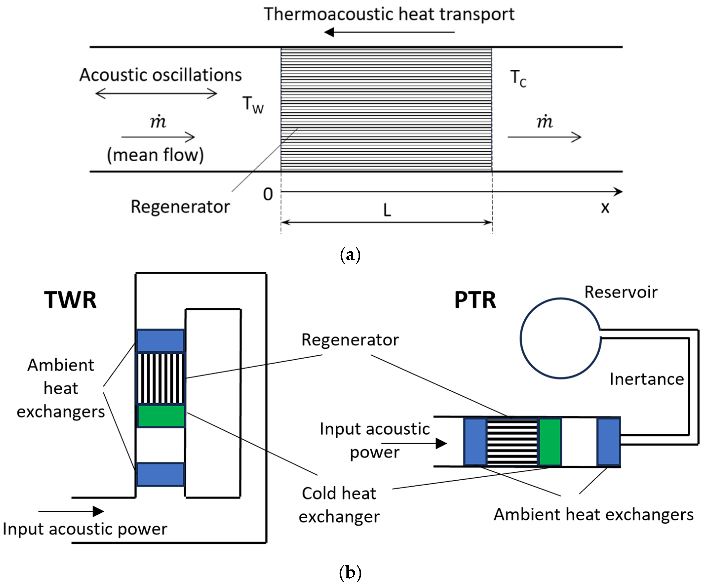
10]. A simplified schematic of the core of this system is shown in
Figure 1a. An acoustic wave passing through a porous medium (called a regenerator) can pump heat from the low- to high-temperature sides. With the preferable properties of hydrogen (e.g., lower viscosity), using it as a working fluid can improve the efficiency of such a refrigerator. In addition, in systems with a mean flow going from the warm to cold ends of a regenerator, hydrogen will also experience cooling, which is more efficient than external cooling due to the elimination of a cold heat exchanger and distributed heat exchange along the regenerator at smaller temperature differences. Thermoacoustic cooling systems of a similar principle have previously been demonstrated with room-temperature air [
11]. If the flow-through cryocooling setup is integrated into a hydrogen liquefaction plant, an additional benefit can be gained by using a catalyzed regenerator matrix that will facilitate ortho-parahydrogen conversion with simultaneous cooling.
In the previous work of the authors [
10], only the standing-wave operation of this configuration was analyzed. Standing-wave systems, where acoustic pressure and velocity oscillate primarily out of phase, are generally easier to design, but they are not very efficient. It is known that traveling-wave thermoacoustic setups, with velocity and pressure fluctuating mainly in phase, have substantially higher performance [
12]. In the current study, a traveling-wave regenerator employing hydrogen as a working fluid is considered, while an analysis of a helium system is also included for performance comparison. The simplified schematics of a traveling-wave refrigerator and a pulse tube (with traveling-wave phasing) that can accommodate the considered regenerator are illustrated in
Figure 1b.
The thermoacoustic mathematical model is described in the next section. After that, the results are first presented for both hydrogen and helium setups without mean flow, together with the optimization of acoustic conditions and pore dimensions. Then, the effect of mean pressure is investigated including subcritical and supercritical hydrogen pressures. Finally, a mean flow is imposed, and the system characteristics are obtained for a range of mass fluxes, including a setup with a catalyzed regenerator.
2. Modeling
For modeling thermoacoustic phenomena in a regenerator, the low-amplitude thermoacoustic theory has been applied [
12,
13]. Acoustic pressure
and volumetric velocity
are assumed to oscillate at angular frequency
,
where
and
are complex amplitudes that vary along the
direction in the regenerator (
Figure 1a),
is the time, and
is the imaginary unit. Spatial variations in these amplitudes are governed by the thermoacoustic forms of the momentum and mass equations,
where
,
, and
are the mean gas density, pressure, and temperature, respectively;
is the ratio of specific heats;
is the Prandtl number;
is the thermal expansion coefficient; and
is the cross-sectional area of the regenerator taken by the fluid. For cryogenic fluid properties, the REFPROP database was used [
14], which utilizes hydrogen properties provided in [
15]. In most calculations with hydrogen presented below, the normal hydrogen properties are utilized. In the cases with ortho-parahydrogen conversion, the variation in the orthohydrogen fraction is considered.
The thermoacoustic functions
and
depend on the fluid properties and pore characteristics. In this study, the expressions for a parallel-plate configuration are employed since, qualitatively, these functions behave similarly for various pore geometries, including random media [
16,
17],
where
is the hydraulic radius, and
and
the viscous and thermal penetration depths,
where
,
, and
are the fluid viscosity, thermal conductivity, and specific heat capacity, respectively. The parameter
in Equation (4) accounts for the thermal effects of the solid matrix,
where
and
are the density and specific heat of the solid material, respectively;
is the plate half-thickness; and
is the thermal penetration depth, evaluated similarly to Equation (7) but with properties of the regenerator solid material.
The thermoacoustic energy equation is presented in the form of the enthalpy flow
along the regenerator [
12],
where
is the mean flow of the working fluid along the regenerator,
is the fluid-specific enthalpy,
is the cross-sectional area of the regenerator taken up by the solid material, and
is the acoustic power flow, computed as follows:
The tilde symbol in Equations (9) and (10) signifies a complex conjugate.
In regenerators with adiabatic walls, the enthalpy flow along the x axis remains constant. The enthalpy flow value is controlled by heat transferred at the heat exchangers (not modeled here) on both sides of the regenerator and the acoustic power flow. Equation (9) can be transformed into a form similar to Equations (3) and (4) with the spatial derivative for the mean temperature .
The governing equations, Equations (3), (4) and (9), were discretized using a finite-difference approach, programmed into Matlab, and numerically integrated along the regenerator to find x-variations in acoustic amplitudes and mean temperature, which determine the cooling power and expended acoustic power. One of the important acoustic characteristics, defining the type of thermoacoustic system, is the phase difference between velocity and pressure fluctuations,
. For example, in standing-wave systems, the acoustic volumetric velocity and pressure fluctuations are shifted by about 90°. In the traveling-wave case considered here, the acoustic velocity and pressure have a zero phase shift (i.e., oscillating in phase) somewhere inside the regenerator. To achieve this, the acoustic velocity must lead the acoustic pressure at the warm end (where acoustic power is supplied). The phase at the regenerator entrance, φ, is treated in this study as an input parameter that is varied to optimize the system performance. In practical setups, this can be achieved by using acoustic networks [
18]. This thermoacoustic model has been extensively validated for moderate oscillation amplitudes [
6,
12].
Besides non-reacting working fluids, the process of converting orthohydrogen into parahydrogen is considered in a setup with a mean hydrogen flow. To model this catalytic transformation, an empirical expression for the variation in the orthohydrogen fraction
, based on test data given in [
19], is applied here:
where
is the local equilibrium fraction of orthohydrogen that is a function of temperature,
is the hydrogen molar mass, and
is the conversion rate coefficient. In this study, a value of 0.0025 mol/(cm
3·s) is utilized for
, which is within the range of experimental results reported in [
19]. Equation (11) is numerically integrated along the regenerator, similar to other governing equations. A variation in the orthohydrogen fraction will affect the fluid specific enthalpy
in Equation (9), effectively resulting in a distributed heat source. This heat needs to be pumped out by thermoacoustic heat transport mechanisms to the warm side of the regenerator.
The regenerator performance metrics, presented in the next section, include the cooling power flux (heat transferred per cross-sectional area in the negative x direction) evaluated at the cold end of the regenerator
, the second-law regenerator efficiency
, and in the systems with mean flow, the cold temperature
,
where subscripts
and
correspond to the warm (inlet) and cold (outlet) ends of the regenerator, respectively, and
is the resonator cross-sectional area. The denominator in the first multiplier in Equation (13) represents the acoustic power consumed in the regenerator. In the systems where mean flow is cooled, no additional cooling load is assumed, and the cooling power flux in Equations (12) and (13) is replaced with the following expression:
where
is the mass flux, one of the input parameters in calculations. It should be noted that in a complete thermoacoustic system, there will be additional losses in other parts (e.g., heat exchangers and resonators), so the overall efficiency will be smaller than that provided by Equation (13).
3. Results
To demonstrate the thermoacoustic theory for a traveling-wave hydrogen setup, shown in
Figure 1, several system parameters were fixed and are listed in
Table 1. The variable parameters include mean pressure, the phase between acoustic velocity and pressure at the regenerator entrance, the hydraulic radius of the regenerator pores, mean flow rate, and cold temperature. Ranges for these variables are also provided in
Table 1. Besides hydrogen, helium is considered for performance comparison. Since the effect of the walls (side boundaries) of the regenerator are not analyzed in the present quasi-one-dimensional model, acoustic and cooling power fluxes (rather than power flow) are utilized in this section. Multiplying the power flux value by a cross-sectional area for the scale of interest determines the cooling power.
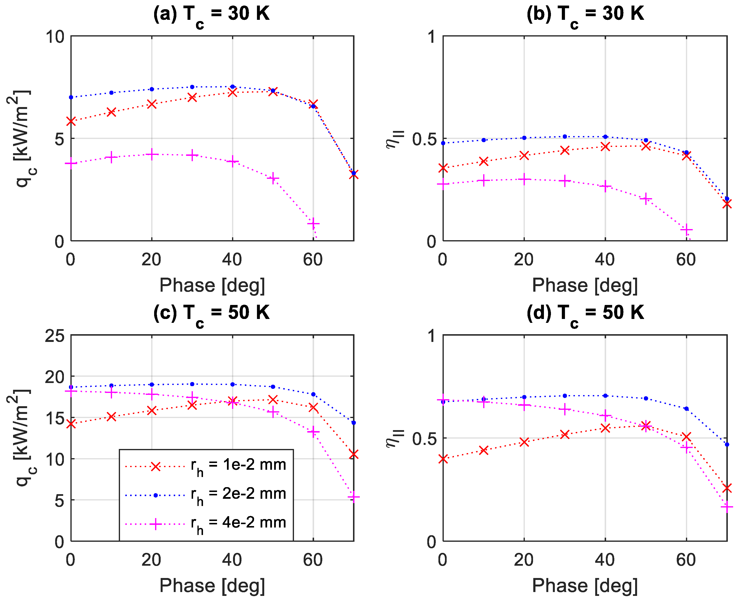
The first set of calculations were carried out at a constant mean pressure of 5 bar and without mean flow to determine the most favorable acoustic phase and hydraulic radius of the regenerator pores. The results for cooling power flux and the second-law efficiency at two cold temperatures are shown in
Figure 2 and
Figure 3 for hydrogen and helium, respectively. One can note the existence of the optimal hydraulic radius and acoustic phase for each condition. At the lowest temperature of 30 K,
mm and
for hydrogen and
and
for helium correspond to the highest second-law efficiencies (about 0.54 for hydrogen and 0.51 for helium) in the studied range. In these conditions, the cooling power fluxes reach 8.7 kW/m
2 and 7.5 kW/m
2 for hydrogen and helium, respectively. At the cold temperature of 50 K, pumped heat fluxes and second-law efficiencies increase for hydrogen to about 20.8 kW/m
2 and 0.76, respectively. An important finding is that for system setups with optimal parameters, hydrogen outperforms helium in both situations, and thus, hydrogen can be recommended as a promising working fluid for use in thermoacoustic cryocoolers.
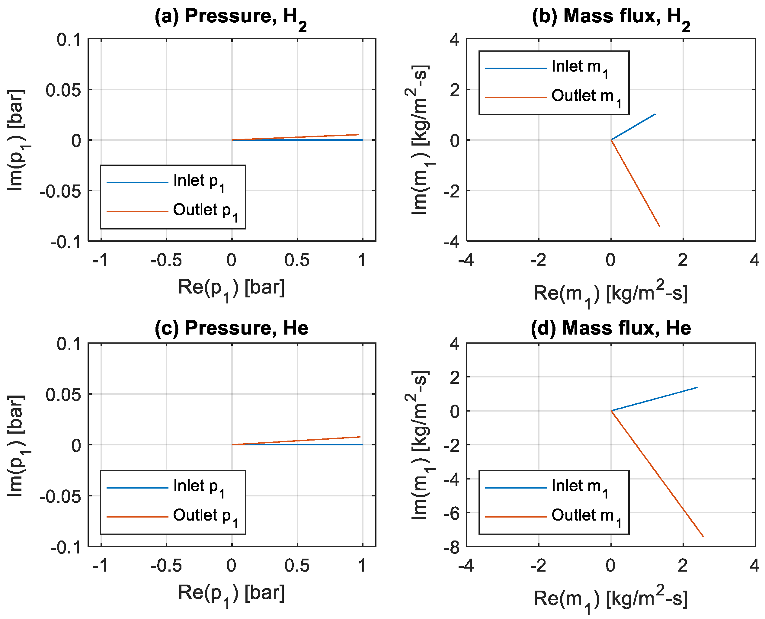
The acoustic phasors for the oscillating pressure and mass fluxes at the inlet and outlet of the regenerator at optimal states and a cold temperature of 30 K are shown in
Figure 4. The pressure amplitudes change little for the selected regenerator geometry, but fluctuating mass fluxes experience strong variations, achieving zero phase shift relative to the pressure fluctuation inside the regenerator. The mass flux magnitudes are greater for helium, especially at the regenerator exit.
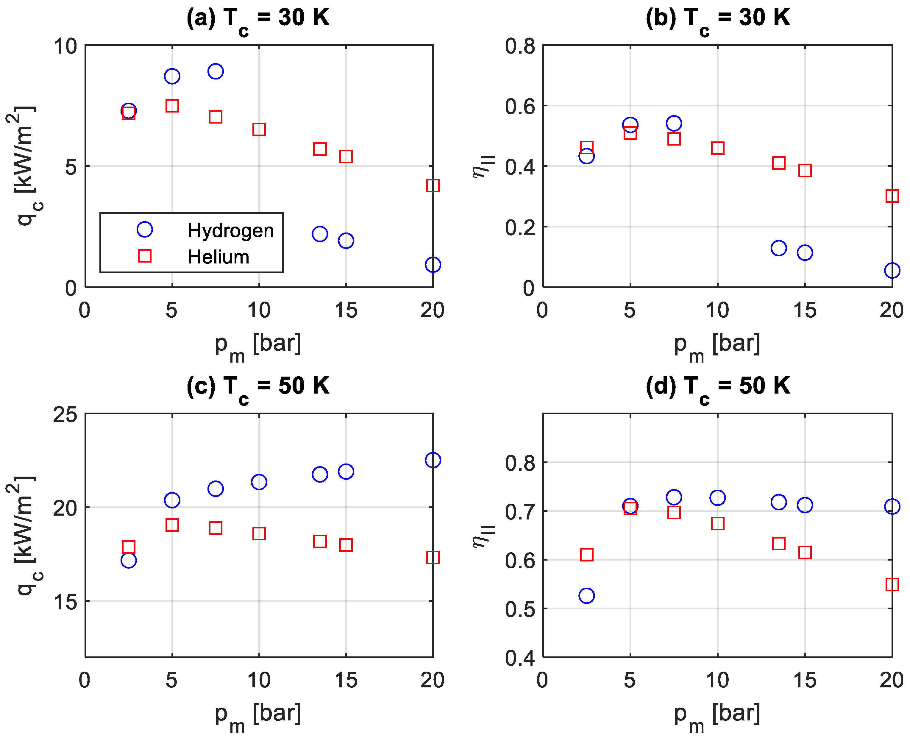
For the determined optimal hydraulic radii and acoustic phases, calculations were also conducted with variable mean pressure, and the results are presented in
Figure 5. At a lower cold temperature of 30 K, the cooling power flux and the second-law efficiency of a hydrogen system increase with the mean pressure (
Figure 5a,b) below the critical pressure of 13 bar. At supercritical pressures, both the cooling power flux and efficiency drop several times, as hydrogen approaches a compressed liquid state with larger density and viscosity. However, at 50 K, which significantly exceeds the critical temperature of hydrogen, the cooling power flux continues to increase, and efficiency almost stagnates with increasing mean pressure, even in the supercritical pressure region (
Figure 5c,d). The helium system demonstrates the highest performance at a mean pressure of 5 bar, for which the present setup was optimized. It manifests a gradual reduction in both cooling power flux and efficiency, without exhibiting the large drops seen for hydrogen, since the mean pressure in the entire studied range exceeds the critical pressure for helium. Thus, the hydrogen system has generally higher performance characteristics, except for the lowest mean pressure and in the situation with supercritical pressures and subcritical temperatures for liquid hydrogen.
Another set of simulations were conducted in the presence of mean flow (from the warm to the cold side of the regenerator) in the optimized conditions found previously at a mean pressure of 5 bar. For hydrogen, cases with and without ortho-parahydrogen conversion were considered. The steady mass flux was treated as a variable parameter, whereas the performance metrics included the cooling power flux (used to cool the mean flow with no additional cooling load on the cold side of the regenerator), the cold temperature (to which the mean flow is cooled down), and the associated second-law efficiency of the cooling process. The results for helium and hydrogen systems, including one with ortho-parahydrogen conversion, are shown in
Figure 6. The cooling power flux and efficiency monotonically decrease at colder temperatures, except for the hydrogen case with ortho-parahydrogen conversion. The cooling power flux in the hydrogen setups is greater, but the cold temperature is higher than with helium, as hydrogen has a larger heat capacity. In the case of ortho-parahydrogen conversion, additional heat is removed, so these trends intensify. At lower cold temperatures, the second-law efficiency is higher for hydrogen, especially with conversion, but the trend reverses at warmer cold temperatures. It can be noted that at lower studied flow rates, the achieved cold temperature of hydrogen approaches the saturated temperature, which suggests potential applicability for this setup in a hydrogen liquefaction system. Moreover, at an even lower flow rate, hydrogen could reach the saturated state near the cold side of the regenerator, but the present model does not include the phase change required to confidently predict this transformation.


