Article

Modal Passport Concept for Enhanced Non-Destructive Monitoring and Diagnostics of Wind Turbine Blades

SIA “D un D Centrs”, 12-26 Jasmuizas Str., LV-1021 Riga, Latvia
*
Author to whom correspondence should be addressed.
NDT 2025, 3(2), 9; https://doi.org/10.3390/ndt3020009 (registering DOI)
Submission received: 7 April 2025 / Revised: 25 April 2025 / Accepted: 27 April 2025 / Published: 30 April 2025
(This article belongs to the Topic Nondestructive Testing and Evaluation)

Abstract

:
One of the most sensitive parts of a wind turbine to environmental influences are the rotating blades. Today, there are many technologies available to assess blade condition, but they all need to be developed to become more cost-effective and more sensitive to fault detection. The algorithms and methods of the modal passport discussed in this paper propose a non-destructive technique already used for helicopter blade condition monitoring and diagnostics. This technique requires adaptation to wind turbine blades because they have larger dimensions, other materials and design, and operate under other conditions. To provide this adaptation, computational and experimental data on the modal properties of the blades must be obtained. The first stage of the study is planned to be performed on a scale model on stationary and rotating test rigs. At this stage of the study, algorithms and methods for the formation of a roadmap to develop a modal passport for a series of composite models of a wind turbine blade are considered. The initial stage of modal passport development included FE modeling of the blade model, calculation of modal parameters, fabricating the blades, and preparing the test equipment. Quantitative assessment of modal tests volume made it possible to plan the step-by-step execution of the roadmap for development and experimental application of the modal passport of wind turbine blade models.

1. Introduction

Rotating blades are critical components of any machine, and in large wind turbines, the fiberglass rotor blades are regarded as the most vulnerable components [1]. Blade failure leads to economic losses and often to environmental damage. To ensure operational safety and to reduce potential failure costs, non-destructive testing (NDT) methods for wind turbine blades are widely used. The authors in [2] categorize NDT methods into those that detect surface and subsurface defects. For instance, visual techniques include inspection by workers suspended on ropes, and different optic systems inspect blades from the ground or using drones [3]. For remote detection of corrosion of metal blades of offshore turbines, special electrochemical sensors are considered in [4]. To detect subsurface defects, thermography, X-ray imaging, 3D laser inspection, and ultrasonic testing [5] are commonly used. Thermography is capable of detecting subsurface defects close to the surface [6]. X-ray imaging allows the detection of a wide range of defects at a certain depth, but requires expensive and bulky equipment [7]. Three-dimensional laser-scanning inspection is more effective for manufacturing than for operation [8]. Ultrasonic testing [9], including specialized UT techniques such as phased array UT eddy current testing of wind turbine [10], is also effective in manufacturing, but application in operation is complicated. Thus, a wide range of NDTs apply to wind turbine blades [10], allowing detection of almost all types of defect, but their effectiveness in operation is limited. Firstly, currently used techniques for blade condition monitoring are not cost-effective. The application of most NDT methods requires stopping the facility, which reduces operating time. In addition, the cost of monitoring is high due to expensive equipment and the transportation costs to the facility and back. This is especially true for offshore wind turbines. Secondly, the NDT of stopped blades has limited efficiency, since it may miss the latent defects that may be detected only during rotation under operating loads. It is also important that the time interval between NDT inspections with turbine stopping may be sufficient for some defects to develop to failure.
A blade condition monitoring method becomes cost-effective if firstly that it can be used without stopping the wind turbine operation, and secondly that it provides predictive methods of maintenance. The diagnostics implemented by such techniques must be highly sensitive to defects at an early stage of their development. Given the “green” requirements, the method must monitor the interaction of the blade with the environment. In some cases, the entry of a foreign object, such as a drone or a large bird, can cause damage that can subsequently lead to the destruction of the blade. In others, the rotating blade may harm the environment by getting in the way of a flock of migratory birds. A system diagnosing the structural integrity using vibrations allows for a comprehensive solution to the problem of blade condition monitoring. Some studies were dedicated to application of the methods based on measuring the vibration response of a blade when it is excited using piezo-ceramic actuator patches bonded to the blade [11]. While these methods allow for a high level of localization, they require intervention in the blade design, the consequences of which may be unknown and require study. Another way is demonstrated by an in situ wireless SHM system based on an acoustic emission (AE) technique [12]. Such techniques allow localization of the acoustic sources that could emulate impact damage or audible cracks caused by different objects, such as tools, bird strikes, or strong hail. For practical application of such a system, it is necessary to solve the problems of the cost of large sensors and measurement systems and the high probability of false alarms. Various methods of contactless monitoring of rotating blades that do not require built-in measurement systems have been proposed. For example, in the method of acoustical damage detection using support vector data description (SVDD), the sound pulse extraction of a blade was investigated in combination with the filter and sliding window [13]. The wavelet packet energy ratios of acoustic signals were introduced to characterize the discrepancy between intact and cracked sound pulses. The authors in [14] proposed using condition assessment of full-scale blades in operation with stereo digital image correlation, applying the new reference frame constructed at the center of the blades’ rotation. Such non-contact monitoring is relatively low in cost; however, it has limited resolution of the defect scale and is insensitive to real-time impacts.
For providing predictive maintenance of blades in operation, the authors considered the techniques of operational modal analysis (OMA) the most promising. The relationships between physical properties and modal parameters (frequency, mode shape, and damping) of the structure is the basis of this approach [15]. The main benefit of OMA is that modal properties of the blade can be determined using naturally excited vibrations without artificial impacts. Thus, any change in a blade’s mechanical features would cause a change in modal parameters. The use of OMA allows the evaluation of modal properties of the blade related to its mechanical properties without stopping operation. There are many examples of using OMA to obtain the frequency and shape of vibration modes of different structures, including wind turbine blades [16,17]. A common problem in most published work is the influence of operational and ambient factors on both the mechanical properties of the blade and on the modal estimates of these properties.
Wind turbine blades operate under cyclically (daily and seasonal) changing conditions, and their rotation speed fluctuates continuously. As studies of a hollow composite structure have shown, a tensile load similar to the action of centrifugal forces on a blade [18] and an ambient temperature [19] significantly influence the modal properties, even if the blade’s state does not change. This means that the modal properties of the blade operating under variable temperature and speed may vary in a range that can significantly exceed the changes caused by a defect. There are also methodological problems in OMA application caused by the influence of the random nature of excitation [20]. In practical application, the limited time interval for vibration measurement plays a role. Due to non-stationary aerodynamic excitation of blade vibrations, the limited measurement time leads to an error in determining the modal parameters. Another error occurs due to the discrepancy between the characteristics of real excitation and the basic assumption of the OMA application, which considers an excitation as uniform in the frequency and time domains. A set of techniques called the modal passport (MP) was proposed [21], allowing the taking into account of the influence of operation mode (rotation speed and pitching) and atmospheric factors (temperature, wind speed, etc.) and to reduce errors of OMA estimation.
A network of sensors providing vibration measurements over the blade, similar to the peripheral nervous system, is the obligatory condition for OMA application. Such a network will allow detecting even a small local impact, for example, a collision with a bird. The sensors and their wiring unit should be integrated into the blade design, while having a minimal effect on its mechanical properties. The frequency range of the measured signals should cover a frequency range of blade’s natural modes as well as the response to a foreign object impact. The lower modes of large wind turbine blades may have frequencies less than 1 Hz, while to ensure sensitivity to external impacts on the blade, the range should cover several kHz. One of the most popular sensor types is a continuous optical sensor with fiber Bragg grating. There are examples of such sensor application for wind turbine blades [22] and helicopters [23]. Some features of optical sensors can limit their use for blades. Thus, the significant mass and dimensions of the measurement equipment do not yet allow the use of optics for a helicopter blade. For a large-scale wind turbine blade, the mass and dimensions are not critical, but there are issues with integrating the sensors into the blade design. Piezoelectric films could be an alternative type of sensor applicable for blades due to a beneficial combination of minimal mass, thickness, and negligible cost with a wide frequency range [24].
The authors envisage the use of modal diagnostic methods for blades with an integrated sensor network within the united system of vibration diagnostics of a wind turbine. Such a system collects and transmits the signals of operating machines and rotating blades to the monitoring center. There are supposed to be two subsystems: one for power units (rotor bearings, gearbox, and generator) and one for a rotor with blades. Unlike the MP for blades, the condition of operating units is assessed using Vibropassport™ technologies [24]. The latter is a methodological and software platform implementing promising methods of vibration diagnostics. Compared with existing NDT, monitoring the condition of operating blades using modal diagnostic methods will reduce operating costs, maintenance downtime, and losses from accidents caused by the development of hidden defects.
Adaptation of the MP concept for monitoring wind turbine blades is the final goal of this research project. The program of MP concept adaptation to wind turbine blades considers three stages. In the first stage, research on scaled models of wind turbine blades in laboratory conditions is conducted. The use of models to adapt MP technologies and procedures simplifies the research, although it does not exempt research on full-scale blades in the final stage. The typical MP of blade models, including typical modal parameters, influence functions, and thresholds, will be the result of the first stage. In the second stage, the MP techniques adopted for blade models will be applied to natural (retired) blades to verify the applicability of technical and methodical solutions for modal parameter identification. These studies are planned to be conducted at ground level with dismantled blades that require less costs. The final stage will be devoted to practical application of the MP concept for full-scale vibration monitoring of wind turbine blades. This stage is planned to be collaborative with blade manufacturers.
This paper considers methodical and technical aspects of the project’s first stage, i.e., the MP technique’s adaptation to the models of wind turbine blades. The first task of the study is to define the procedure for the concept’s application to blade models, including MP basics, methods of testing, data development, and condition monitoring. Development of technical requirements for blade models, measurement and testing equipment, as well as a series of estimations and tests is another task. Section 1 of the paper focuses on the roadmap of the first research stage and on justification of the methods applied, using experience from similar modal studies. Section 2 discusses the research program, methods, and blade model samples required for adaptation of MP techniques for turbine blades. The results of modeling and preparation of both the blade models and the testing equipment are presented in Section 3, the Discussion in Section 4, and Conclusions in Section 5.

2. Materials and Methods

2.1. Problem Analysis

The use of MP for monitoring the blade of an operating wind turbine involves determining the modal properties of blades and taking into account the influence of operating mode and ambient conditions. The algorithms of modal parameter calculation using measured vibrations and accounting for influencing factors are the core of MP. The set of technical solutions for measuring vibrations of a rotating blade and transmitting data are the basic provision of actual MP application. Successful trials of MP application for diagnosing helicopter blades [21] allow the expectation of positive results for wind turbines, provided that their specialties are taken into account. The design of wind turbine blades and their operating conditions differ significantly from helicopters. Firstly, the modal properties of helicopter and wind turbine blades differ due to materials, design, and dimensions. Secondly, the rotation speed of a wind blade is noticeably less. Given these differences, it is necessary to adapt technical solutions and MP algorithms (proven for helicopters) for real wind turbine blades. Research on adaptation of an MP on full-scale blades requires significant costs and a long time, which can be reduced carrying out the initial adaptation on scaled models in laboratory conditions. Successful results of trials on models would confirm the feasibility and reduce the amount of work on adapting the MP to full-scale additions.
The objective of this study was to analyze the content and assess the volume of experimental studies on adaptation of an MP for wind turbine blades using blade models as specimens.

2.2. Modal Passport

2.2.1. Concept

The MP concept provides an assessment of the structure’s condition based on its modal parameters, taking into account the influence of the operating mode and external factors. The passport is developed for a specific blade type and takes into account a range of operating modes and external conditions.
The MP includes a typical and an individual part. The first one characterizes a virtual “typical” blade that has properties common to all blades of this type. These properties are characterized by the modal model having the parameters of typical modes and by the influence of operational and ambient factors on the typical modal parameters. The typical part of the MP also includes the parameters of testing, recording, and processing data applicable to all blades of this type, as well as the threshold values of diagnostic parameters. All components of the typical passport are determined based on test data for blades of the chosen type. The typical MP of the blade is based on the modal dataset obtained from testing the “healthy” blade samples. The set of typical modes is the principal part of the MP, and each of those is characterized by basic parameters: frequency, damping, and shape. The individual part of the MP contains modal parameters obtained from vibration measurement data for a specific blade, using methods of recording and processing data of the typical MP. The individual part of the passport exists only for a particular blade and contains the parameters of its typical modes. The individual MP of a particular blade includes information on the parameters of external and operational factors under which vibration of the blade was measured. Ambient (atmospheric) influence is mainly characterized by temperature, while the pitch and rotation speed allow take into account the influence of static loads on the modal properties of the operating blade. The influence functions that take these factors into account allow practical diagnosis of the blade using modal parameters obtained under arbitrary operating modes and external conditions. Thus, the measured blade’s data (vibration, rotation signal, operating and ambient parameters) from one side and properties and functions of a typical MP are used to diagnose a particular blade.

2.2.2. Diagnostics in Modal Space

The MP allows monitoring and diagnosing in the modal diagnostic space, the coordinates of which are characterized by values of the modal parameters. The diagnostic parameter in this space is the modal distance, which measures the difference between two modal states, for instance, the actual and the reference ones. The dimension (number of axes) of the space can vary depending on the tasks being solved.
The modal distance between two points in modal space, characterizing two states of one mode, is an elementary diagnostic parameter. Coordinates of the point reflecting the shape of the m-th mode in the modal space have Nm axes in accordance with the number of degrees of freedom (DOFs) of the modal model. The modal space of three basic parameters of one mode (frequency, damping, and shape) has dimension Nm + 2, and the maximum possible dimension of the modal space is determined by the number M of blade modes:
n m s d = M N m + 2
The elementary modal space distance (MSD) along each axis is calculated as the normalized difference between the measured and reference (index 0) values. The elementary diagnostic parameters (single mode) of frequency f, damping D, and eigenvector s of the m-th mode are calculated:
d f ¯ m = f m f m o / f m o
d D ¯ m = D m D m o / D m o
d s ¯ m = s m s m o / s m o
To diagnose a blade, an aggregate diagnostic parameter can be calculated for each basic modal parameter, taking into account all M blade modes. The aggregate parameter is and normalized to the number of modes used (M) so as not to depend on their number, which may vary among similar blades:
M S D f = 1 M m = 1 M d f ¯ m 2
M S D D = 1 M m = 1 M d D ¯ m 2
M S D s = 1 M m = 1 M n N d s ¯ m n 2
An abnormal blade condition is fixed if the MSD value exceeds the threshold value [MSD]:
M S D > M S D
There are “healthy” and “specific damage” thresholds, and both are established experimentally. In the stage of “healthy” state definition and setting appropriate thresholds, the sets of “healthy” blades of the same type are tested to determine modal parameters in the defined frequency range. Based on the test results, a set of sustainable modes is selected that models parameters that form the core of the modal passport of this blade type. Based on the distribution of each modal parameter (frequency, damping, and shape) of all sustainable modes, the distribution areas of all parameters are defined. Then, “healthy” thresholds are established for each parameter included in the modal passport. Thresholds of the “specific damage” state are set in a similar way.
The thresholds for any type of blades could be established using the techniques of the modal passport; however, the modal passport does not allow adjustment of the modal parameters of one blade type to another one.
The modal distance in the space of the three basic modal parameters is used as an integral diagnostic parameter. The scales of the frequency, shape, and damping parameters differ, so the integral parameter is calculated in a harmonized modal space. Harmonization is achieved by normalizing the axis of each parameter to the upper boundary of the typical distribution area. The typical distribution areas of modal parameters (frequency [f], damping [D], and shape [s]) are determined experimentally using the test series of blades of a given type [20]. Taking into account the above, the integral diagnostic parameter is calculated:
M S D H = 1 M m = 1 M d f ¯ m f m 2 + d D ¯ m D m 2 + n N d s ¯ m n s m 2
where index n reflects the number of the eigenvector element (1 … N).
In the harmonized scale (normalized to the upper limit of the reference state), a value exceeding 1.0 indicates that the blade has gone beyond the normal state.

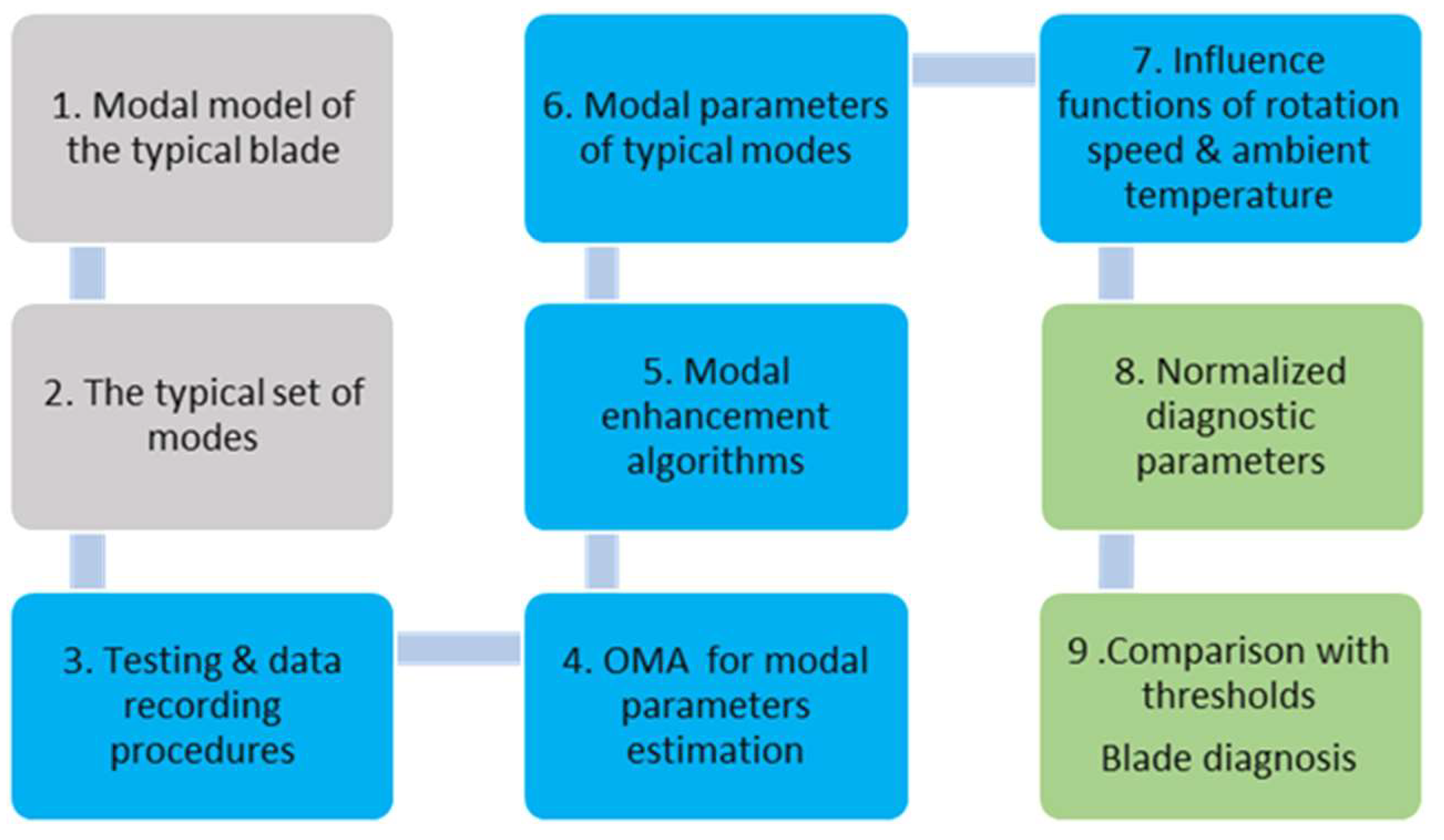
2.3. Blade Passport Preparation and Application

MP application for blade monitoring becomes possible after the typical passport is created for the specific type of blade. The sequence of steps for MP development and its application for diagnosis and monitoring is considered below and illustrated by the diagram in Figure 1. The research and testing are divided into 9 steps, which are color-coded. The first two steps (gray) relate to developing the typical passport for a specific type of blade. Algorithms and procedures of steps 8 and 9 (green) relate to applying the individual passport to diagnosing the particular blade, and the remaining (blue) steps are used both in the stage of typical passport formation and in the use of an individual passport.

2.3.1. Blade’s Modal Model

The MP is based on the modal model of the blade, common to all samples of this type. The parameters of the model are determined by the mechanical properties of materials and design of the blade. The design specialties influence the modal properties. A helicopter blade with a solid beam demonstrates mainly natural modes of a beam kind, including bending and torsional ones. Although wind turbine blades also have an aerodynamic profile, they differ from helicopter ones, having a reinforced shell with a cylindrical root for connection to the rotor. This specialty provides different shell modes in addition to bending ones. Initially, the modal parameters of the blade model are estimated using FE modeling methods. These modal estimates ensure the planning of the testing stage, including measurement setup. The modal model is validated by applying the modal testing techniques, basically OMA. To interpret the blade vibrations measured by sensors during testing, modal analysis methods use DOFs of vectors of the blade geometric model, which is illustrated in Figure 2.
The more sensors, the more vibration modes are distinguished, and the sensitivity to defects could be higher. However, with more sensors, the cost of the system and the volume of calculations increase. Typically, number measurement channels limit the number of DOFs; therefore, optimization considers the best DOF distribution on the modal model to ensure a criterion. The optimization criterion in this study is the maximal number of potentially identified modes with limited DOFs. The shapes and frequencies of simulated modes required for optimization are provided by the modal modeling. As the experimental set of equipment in this study considers 24 measurement channels, sensors are distributed in 8 sections along the blade model, with 3 sensors in each. Sensors are placed on surfaces of upper and lower pressures of the model, which allows the identification of both bending and shell modes and increases the number of potentially identified modes.

2.3.2. The Typical Set of Modes

The MP is able to diagnose the blade using the parameters of typical modes that are common to all blades of a given type. The composition of typical modes and their parameters is determined during tests of a batch of identical blades under reference conditions. Only those modes that are detected in the majority of tested samples of the batch are considered as the typical examples. Adaptation of the MP to wind turbines is initially carried out on a batch of scaled models of such blades. The materials and design of the blade models correspond to the full-scale blades, and manually manufactured samples are used to conduct modal tests for determining the typical modes and their parameters. The number of typical modes that can be determined based on the test results depends on the DOF number and configuration. Based on experience of using the MP for helicopter blades, it can be estimated presumably to be from 10 to 30.

2.3.3. Testing and Data Recording Procedures

When testing each blade’s model sample, the MP takes into account the parameters of only those modes that correspond to the typical ones. Excitation and measurement of the sample to determine the modal parameters is carried out in accordance with typical vibration testing and recording procedures. For a stationary sample, the testing procedure includes the parameters of vibration excitation, including the location, strength, direction, and duration of the pulse impacts. For a rotating sample, these procedures also consider the routines of signal measurement and recording over a range of rotation speed, and if necessary, with additional aerodynamic excitation. In order to ensure the calculation of parameters and identification of typical modes, the procedures of signal registration consider the frequency range of measurement, the sampling frequency, and the duration of records. Depending on test conditions, the registration procedure may consider the continuous registration or repeated records depending on operational (rotation frequency) and external (atmospheric) factors. Temperature influences the modal parameters, and this is taken into account in the test procedures. During stationary tests of blade models, the thermal chamber (Section 2.5.2) maintains a stable unchanged temperature within repeated tests, and the test results are then used to calculate the influence functions (Section 2.3.7). Dynamic tests (more continued) of models on a rotating bench are carried out in a lab at a constant temperature.
Optimization of the registration procedures decreases the error of modal parameter determination due to reduction of the influence of random factors. More detailed application of the procedures is discussed in Section 2.5.
Considering natural wind turbine blades, the temperature influences the modal parameters, in addition to fluctuations in rotation speed and pitch. Therefore, measurement procedures for turbine blades will consider permanent temperature monitoring of blades and modal parameter recalculation applying the influence functions.

2.3.4. Estimation of Modal Parameters

For the initial assessment of modal parameters, OMA methods use vibration signals measured during tests and transformed into digital form. For modal estimation, commercially available software (SW) packages Artemis are applied. This SW relates recorded data to DOFs of the geometric model and realizes the most usable OMA techniques (estimators). Based on the authors’ experience, sensitivity of modal estimators in frequency and time domains differs in regards to different modes of different structures. If the EFDD technique better estimates one type of mode, CVA may identify more modes of the same structure. Therefore, the MP generalizes estimates of at least five standard and acknowledged estimators (EFDD, CVA, PC, UPC, and UPCX). Each technique (estimator) identifies natural modes of the tested blade (or scaled model) and provides primary estimates of those modes’ parameters (frequency, damping, and shape). Such primary estimates are not applicable to health monitoring due to uncertainty caused by random components of structural vibrations and measurement errors. The latter becomes evident when different OMA estimators identify blade modes differently in developing the same test data. The influence of random vibrations on the uncertainty is expressed in the modal estimate variation of the same estimator when processing repeated tests of the same blade.

2.3.5. Modal Enhancement

Modal enhancement allows a reduction in the uncertainty of primary estimated modal parameters. The enhancement is the set of procedures for averaging of modal estimates produced by different modal estimators from data of different measurements. The modal enhancement provides vibration noise suppression and uncertainty reduction. There are two stages of primary estimate development: the preparation and the averaging.
The preparation stage considers the sequence of eigenvector transformations, including modal shape normalizing, mode grouping, and modal phase matching. Different estimators of commercial SW provide different scales of eigenvectors describing the modal shape. Normalizing the modal shape to a common (−1.0...1.0) range allows compatibility of eigenvectors provided by different estimators. Each n-th element of the eigenvector s n m e s t of the m-th mode computed by the modal estimator is normalized:
s n m n o r m = s n m e s t / n = 1 N s n m 2
The modal grouping procedure includes identifying similar modes from the set of primary estimates with normalized shapes. The modal assurance criterion (MAC) [25] allows identification of similar modes by comparing the pair of its eigenvectors. If the MAC tends to 1.0, the pair of mode shapes is almost identical. As a criterion for similarity, the minimum acceptable MAC is fixed. For instance, for similar mode detection from estimates of experimental data of helicopter blades, a lower MAC limit of 0.98 was applied successfully. Similar modes with MAC exceeding the lower limit are clustered in similar modal groups. Based on the results of modal grouping, K unique groups of modes are selected, and each group includes M k similar sustainable modes. The preparation stage is completed with phase matching within each group of modal shape estimates. The matching is required, as OMA estimators may reflect an eigenvector of the same mode in opposite phases. The matching involves the checking of phase compatibility between modes in the group and inversion of eigenvectors with opposite phases.
The modal enhancement reduces the uncertainty of computed modal parameters and increases the accuracy of diagnostics using these parameters. The enhancement procedures differ for eigenvalues (frequency and damping) and for eigenvectors describing the modal shapes. For m-th mode, the enhanced means of frequency f ¯ m and damping d ¯ m are calculated as the arithmetic mean of the M k estimates of the k-th group:
f ¯ m = 1 M k 1 M k f m k ; d ¯ m = 1 M k k = 1 M k d m k
The enhancement procedure for modal shape s ¯ n m considers averaging each of N elements of M k prepared eigenvectors s n m k for each k-th group:
s ¯ n m = 1 M k k = 1 M k s n m k
Uncertainty in the enhanced modal parameters is estimated using an assumption of Gaussian distribution of primary modal estimates. This assumption was proven by distribution of modal OMA estimates experimentally obtained for helicopter blades that turned out to be close to normal [20]. The distribution area of enhanced modal parameters with 99.7% probability with Gaussian distribution is characterized by triple standard deviation of its M k estimates:
f m = 3 1 M k 1 M k f m k f ¯ m a v 2 ;   δ d m = 3 1 M k 1 M k d m k d ¯ m a v 2
The uncertainty of the enhanced eigenvector is estimated for each n-th element of enhanced eigenvector by triple standard deviation in the group of M k modes and is presented as a vector δ s n m :
δ s n m = 3 1 M k 1 M k s n m s ¯ n a v m k 2
As the global parameter of uncertainty δ s m of the m-th mode, the scalar value may be used:
δ s m = 3 N 1 N δ s ¯ n m 2
The enhanced modal parameters computed from the test data using Equations (11) and (12) reflect mathematical expectations of the modal parameters of the tested blade. The values computed using Equations (13)–(15) characterize the uncertainty level, with which the parameters above are calculated.

2.3.6. Modal Parameters of Typical Modes

The MP diagnoses the particular blade by comparing the modal parameters (calculated using measured vibration) with the reference state parameters. The set of modes that are identified in testing a particular sample only partially match the typical modes. Therefore, only those modes (computed from measured vibrations) that are similar to typical ones are selected for diagnostics. The selection of modes is performed using the MAC, which compares the enhanced eigenvectors with typical ones [25]. An MAC value close to 1.0 indicates the similarity of the compared modes. For example, an MAC of at least 0.98 was used as the threshold for selecting modes of hollow composite structures [18]. The parameters of the selected modes characterize the current state of the blade and are used for subsequent MP procedures.

2.3.7. Influence Functions

Blade health monitoring should be conducted in different conditions depending on wind speed and at different temperatures. As shown in modal studies of composite structures [19], ambient temperature, which affects the mechanical properties of the material, can significantly change the modal parameters. The rotating blade is a subject of centrifugal and bending/torsional aerodynamic loads, the static component of which also affects the modal properties of the composite structure [18]. Since the threshold values of the diagnostic parameters are set for reference conditions, it is necessary to consider the influence of the above factors on the measured modal parameters. In the MP, the influence of external factors is taken into account by influence functions that in laboratory conditions (for scaled models) are determined experimentally. The test procedure and the equipment used are discussed in more detail in Section 2.5.
Influence functions express the deviation of the modal parameter from the reference value in response to changes in the influencing factor. The modal passport considers the modal parameter as a linear function of difference between actual and reference values of the operating factor. This function is defined for a fixed temperature range, for which the linearity assumption can be considered to be true. The dependences for modal parameters on temperature are shown in Equation (16):
f ¯ m T = F m f T T T 0 + f m o D ¯ m T = F m D T T T 0 + D m o s ¯ m T = F m s T T T 0 + s m o
For instance, frequency on temperature influence function F m f T indicates the gradient of the m-th mode frequency for a 1 °C temperature change. The frequency influence functions are common for all samples (blade models) in the determined range T l o w T h i g h . Though modal frequencies at reference state f m o may slightly vary between samples, the MP considers they have the same frequency increment for the same temperature change. Influence functions are determined experimentally by testing the batch of samples in the operating range of an influencing factor. In addition to temperature, static loads are influencing factors also. An operating blade is subject to two static loads: the tensile load caused by centrifugal forces dependent on rotation speed, and bending/twisting forces dependent also on a blade pitch. Thus, for a rotating blade (and its scaled model), the influence functions of static loads and temperature need to be defined for all modal parameters in the operating range.
The influence functions are used for adjustment of measured and computed modal parameters to the reference state, for which the thresholds are established. Influence functions are established for a full range of operating conditions, including temperature, rotation speed, and pitching. The techniques of establishing influence functions can be different. For blade models, testing on a rotating test bench will be used, but for real blades, the influence functions will be established using natural test data. These functions are the same part of a blade’s modal passport as the set of sustainable modal parameters and the thresholds.

2.3.8. Reduced and Normalized Modal Parameters

Commonly, modal parameters of the vibrating blade are evaluated under arbitrary conditions, for instance, characterized by load L and temperature T. If they differ from reference values, for which the thresholds are defined, the computed modal parameters should be recalculated to reference conditions ( L 0 ,   T 0 ) using influence functions. For instance, considering linear superposition of both impact factors, the recalculation of the modal frequency for m-th mode is derived from Equation (16):
f ¯ m T = F ¯ m F m f L L L 0 F m f T T T 0
In the same way, the parameters of damping and eigenvector can be recalculated:
D ¯ m r = D ¯ m F m D L L L 0 F m D T ( T T 0 ) s ¯ m r = s ¯ m F m s L L L 0 F m s T ( T T 0 )
After reduction to reference conditions, the blade modal parameters could be normalized to reference values in a way similar to Equations (2)–(4).

2.3.9. Blade Diagnosis

Modal parameters reduced to reference conditions and normalized are used to calculate diagnostic parameters in accordance with Equations (2)–(7) and (9). Depending on the number of modal components used in the state space, the diagnostic parameters are divided into three levels: integral (for a whole blade or sample), aggregate (one kind of parameter), and elementary. Some examples of blade diagnosis applying different kinds of modal parameters are considered below.
The blade condition assessment begins with the use of the integral parameter (Equation (9)), which considers all the modal parameters identified during testing. Since the parameter is calculated on a normalized scale, the integral blade condition can be assessed without taking into account its history, i.e., based on the data of a single test. From the definition of the integral parameter, it follows that if its value is less than 1.0, the blade condition remains in a reference state.
Exceeding the specified limit indicates an abnormal condition, the reason for which can be determined considering the relationship of the aggregate parameters of frequency, damping, and shape (Equations (5)–(7)). For example, sun radiation “aging” the composite material of the entire blade may lead to a uniform decrease in the stiffness over the blade [26]. With a stiffness loss, the global parameters of the blade’s modes (frequency and damping) change more, while the normalized mode shapes may change less. A similar effect can be exerted by moisture absorption [27], which increases the mass of the material of most of the blade and leads to a change in its modal properties. Another type of damage, such as loosening of the blade fastening [28], would change dominantly the parameters of the low-frequency modes, and the higher the modal order, the effect less. If the shape aggregate parameters play a dominant role in the anomaly, then the latent defect may be identified and the damage can be localized [29]. For localization, the elementary diagnostic parameters are used (Equations (2)–(4)). These parameters characterize the change in individual modes [21] and those that would respond, for which the damage location is near the highest-stress zones [30].
The MP allows not only monitoring of a particular blade but also diagnostics of blades based on the data of single test or measurement. In this case, the parameters of a virtual “typical” blade are used for comparison, but not the parameters of the reference state of this blade. Such diagnostics can be used to reject blades with hidden defects for which there are no data from previous tests.

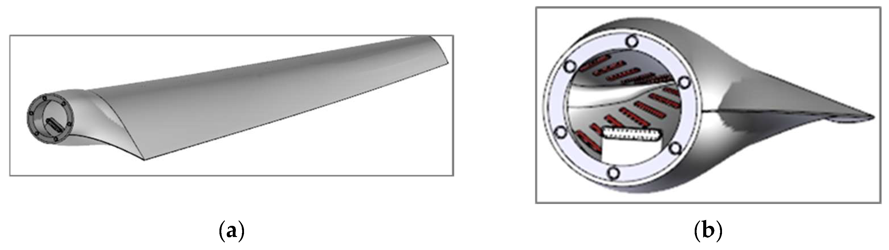
2.4. Testing Models of Blades

For experimental studies required to adapt the MP algorithms and procedures to wind turbine blades, scaled blade models are manufactured. The materials (fiberglass plastic) are similar to typical blades, and the hollow design with reinforcing elements are used for manufacturing these models. The number of samples is determined based on the research objectives and the test program. The main objective is to develop a typical MP of the blade models, and the greater the number of samples tested, more accurate the parameters of this MP will be. In addition, the samples might be used to study the seeded fault influence on modal parameters. In practice, time and cost factors limit the number of samples, so it is determined taking into account the minimum number that ensures the solution of the test problems. A typical wind turbine rotor has 3 blades, so the test setup for blade models testing (described in Section 2.5) is also designed for a rotor with 3 blades. Taking into account the possible replacement of the blade set, a minimum number of 6 identical blade models was determined. The batch of 6 samples was accepted as the minimum sufficient in order to develop the typical MP of the samples. Technical requirements for blade models and the testing equipment required are given in Table 1.
The sizes of the projected thermal chamber and the rotor test bench limit the maximum length (2 m) of the blade model. The mass and size of the measurement unit, which has to be placed on the rotating hub of the bench, limits the channel number (24). As signals of a maximum of 24 sensors can be simultaneously measured, the number of sensors of the sample was also limited to 24. The temperature range for model testing (−15 … +45) was less than the operating range of full-scale blades, since the testing task is limited by the MP adaptation to models only. The upper limit of the rotation speed range (900 rpm) was selected taking into account the criterion of similarity to the peripheral speed at the ends of full-scale blades. The model design with integrated sensors is illustrated in Figure 3.
In this study, piezoelectric films are used as sensors, allowing measurement of the dynamic stresses of the surface layer of the vibrating blade model. The location of the sensors on the inner surface of samples was chosen based on that planned for the full-scale wind turbine blades. This solution allows prevention of the impact of precipitation, dust, and other environmental factors on the sensor network. The location of the sensors, taking into account their limited number, will be determined based on the results of the FE modeling. The wiring system is common to all sensors and ends with the connector for the cable connecting the blade to the measurement unit on the rotor hub. The root part of the model is reinforced to provide cantilever fastening and to transmit dynamic and static loads in different test modes.
The type and dimensions of the sensors used, their operating principles, signal measurement, and interpretation methods have been previously investigated and published by authors, including in [20,24]. Experimental studies of modeling and testing of composite blades, as well as similar composite specimens [18,19,21], have confirmed the effectiveness of the applied sensor configuration for identifying expected modes.

2.5. Testing and Measurement Systems

The special test equipment and the measurement system are prepared for testing the models. The test equipment provides several functions for different testing conditions. Firstly, it simulates external effects (rotation and temperature variation) to which a wind turbine blade is exposed in natural conditions. Secondly, it provides dynamic excitation of the blade model in non-rotating tests in accordance with the OMA requirements. Thirdly, it provides measurement and recording of signals of the vibrating blade as well as parameters of external factors (temperature, rotation speed and pitch). Depending on the test mode, the parameters of dynamic excitation of the sample are chosen to provide a typical set of modes. The measurement system allows recording of the vibration of the blade model in static and rotation testing, as well as the parameters of external effects, including temperature and rotation speed. Two benches, the thermal chamber and the rotating bench, will be used in combination and separately to conduct tests related to the formation of a modal passport.

2.5.1. Rotating Test Rig

The bench for testing blade models in rotation is used to study modal properties under the action of centrifugal and bending loads. The data acquisition unit (DAU) measures the vibration signals of the blade model rotating with rotation speeds. The projected bench layout is shown in Figure 4.
The horizontal plane of rotation was chosen to simplify the design and reduce the bench sizes. The rotating test bench allows testing of the modal parameters’ dependence on rotation speed in a given range. The task is to validate the diagnostic method that compares the modal parameters estimated at arbitrary rotation speeds of a blade with the thresholds fixed for reference conditions. For such a task, the rotation plane does not matter, as there is no task to relate the results of this experimental study directly to wind turbine blades.
The blade model is mounted to the rotor hub through the ring mount on the root part. The design of the hub and the model’s root allows installation of all three samples with the same pitch, which may be regulated in a given range. The model’s pitch can be additionally adjusted within a limited range for aerodynamic balancing of the rotor. The DC electric drive of the bench provides the rotor with blade rotation speed of 0 to 900 rpm, the upper limit of which corresponds to the peripheral speed of the blade tip of about 0.8 M. The rotating part of the measurement system, installed on the hub, measures and converts the signals from the blade sensors and transmits them online for registration on the computer of the fixed part of the system. The computer generates data files using the data obtained during the tests through the Wi-Fi receiver, and then estimates the modal parameters (p. 2.3.4) and enhances them (p. 2.3.5).
By conducting a series of tests at several rotation speeds, it is possible to determine the dependence of each modal parameter of the blade’s model on the rotation speed in a given range. By repeating the tests for each of three rotor blade models, it will be possible to determine the general dependence of the modal parameters on the rotation speed for these model types. As part of the MP of the blade models, the influence functions of rotation speed ensure the reduction in the modal parameters obtained at an arbitrary rotation speed to reference one. The design of the bench also allows testing the dependence of the modal parameters on the pitch.

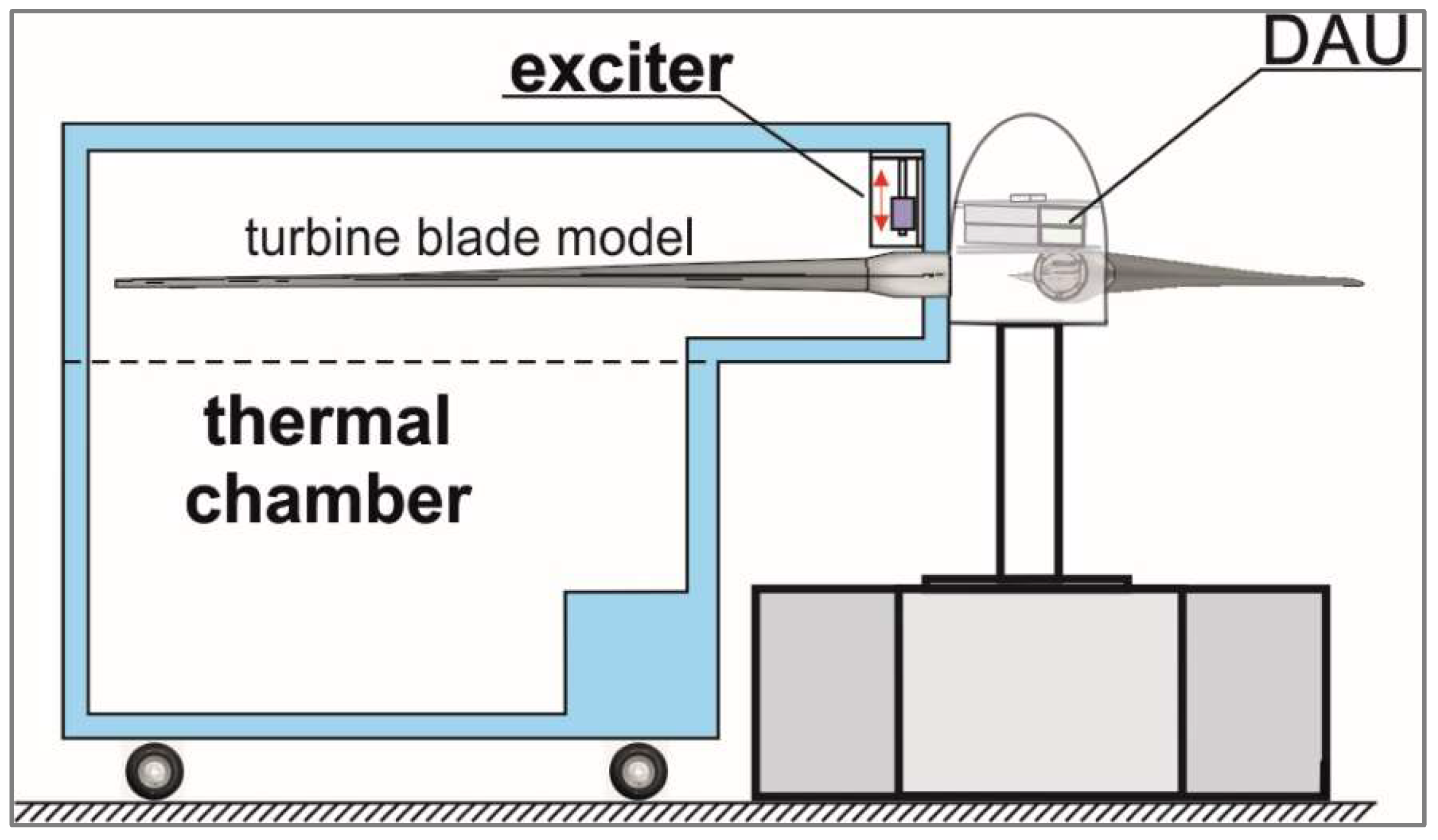
2.5.2. Thermal Testing Chamber

The thermal chamber rig provides modal tests of the static blade model installed on a rotating bench as part of the rotor. In such a way, the boundary conditions correspond to the rotating blade, although without centrifugal force. The testing setup using the thermal chamber is shown in Figure 5. To excite vibrations of non-rotating blade model, the automatic pulse actuator acts on the sample’s root inside the thermal chamber that provides a given temperature. The impact force and duration of the excitation are regulated to achieve vibrations of the sample in a given frequency range sufficient to determine the parameters of typical modes. The pause between impacts is determined as the duration that is sufficient for measuring the model’s damped response to impacts. The thermal chamber design provides for input of the cables for actuator control and the model’s sensor network.
The testing and registration procedures for a statically fixed blade may take a significant amount of time, during which the temperature must remain constant. The thermal control system maintains a stable temperature at a given level in automatic mode. Automatic vibration excitation and thermal control systems ensure repeatability of test conditions for a series of models. The tests in a thermal chamber provide a consistent solution for thermal stability at a given level. First, tests are carried out at a reference temperature supported at the stable level. Based on the results of these tests, using the modal estimation and modal enhancement procedures, a typical set of modes and their parameters is determined. Modal tests to determine the parameters of a typical MP are carried out on all 6 samples of the blade models. Second, the temperature influence functions on the modal parameters of models are determined using the tests in the temperature range from minus 15 °C to plus 45 °C. The influence functions will be determined for three blade models that are part of the rotor. The result of the blade model testing in the thermal chamber will be the typical set of modal parameters in the reference condition and the typical influence functions of basic modal parameters, including frequency, shape, and damping.

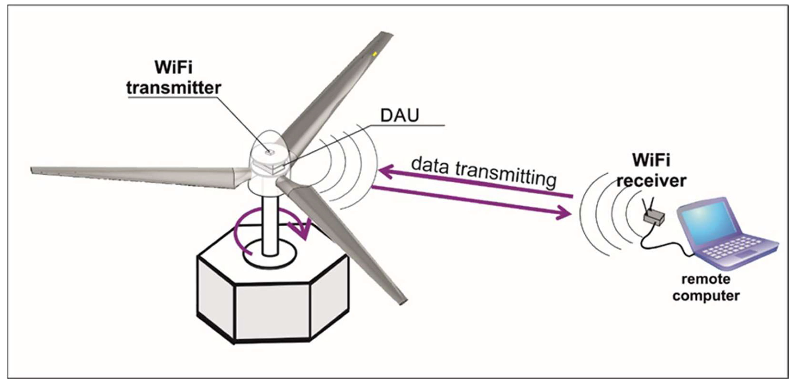
2.6. Measurement System

The measurement system, as shown in Figure 4, comprises rotating and stationary parts.
The rotating part is placed on the rotor and includes:
  • 20 piezoelectric sensors, integrated into a blade model;
  • Rotation speed sensor;
  • Two 12-channel data acquisition units (DAUs) connected via the switch and powered by batteries;
  • Wi-Fi transmitter, connected to DAUs;
  • Cables from the sensors connecting to DAUs.
The stationary part, remote from the rotating test bench at a safe distance, includes a Wi-Fi receiver connected to a computer with the required software installed, providing measurement system control, data registration, and monitoring.
The measurement system provides synchronous measurement of 24 inputs with a sampling rate of 8192 Hz and a 24-bit rate. Data from the DAU are transmitted to a remote computer at 300 MB/s.

3. Results and Discussion

Adaptation of the MP for the blade model requires a significant amount of experimental research. To estimate the upcoming work, the number of tests and analyzed modes must be taken into account. For rough estimation of the modal properties (mode number and frequency range), the FE model was used (Figure 6).
There are 80,626 elements (191,174 nodes) of the model, including 30,507 solid elements (43,335 nodes) of the root shown by red on Figure 6, and the other elements of the blade are shell. For this study stage, the frequency range was limited to 400 Hz. Modal frequencies of the first 16 calculated modes in this range are presented in Table 2.
Aiming for optimization of the sensor network for manufactured blade models, the shapes of calculated modes were identified. The indices of the identified modes are given in the third row of the table. The letter index designates the type of oscillation mode (F—flapping, R—rotation, T—torsional, S—shell), and the number in front means the order of the mode. For modes that have both beam and shell features, both indices are indicated. Figure 7 illustrates examples of a typical beam mode using the 4th flapping—4F in Figure 7a and the shell mode 2TS in Figure 7b. Table 2 shows that up to 200 Hz, the modes are of a beam kind, while at higher frequencies, some shell modes appear. The hollow composite samples with relatively thin walls supports feature of both a beam and a shell.
The sensor network configuration should be sensitive to various potential defects that can differently affect beam modes (like loss of material rigidity) and shell ones (like local skin surface defects). Considering this, an arrangement of sensors in a chain along the model axis mainly provides identification of beam-type modes, while sensors located along the chord also allow identification of local shell modes. Thus, to identify two half-waves along the chord observed in the 2TS shape (Figure 7b), at least four sensors are required in this direction. Considering the limited number of sensors in the planned tests, the configuration 4 × 6 was selected, where three sensors in each of eight sections are distributed along the blade. Such a configuration will allow identification of both shell modes with one to two half-waves and beam modes up to seven. Taking into account the order of potentially detectable modes corresponding to indices 7F and 2TS, the upper limit of the frequency range of the modal parameters studied is estimated to be about 400 Hz. According to the simulation results, up to 15 modes fall into this range. Taking into account the approximation of the calculation results, as well as possible influences of test conditions on the modal frequencies, the upper limit of vibrations measurement is set to 600 Hz.
Experience in experimental studies of the modal properties of composite samples [20] showed that the number of modes identified using the test results can be two or more times greater than their calculated number. Thus, the number of natural modes identified by the OMA methods for each model test is preliminarily estimated up to 30.
Preliminary assessment of the frequency range of modal studies and the number of modes allowed preliminary estimation of the main parameters of the MP model, as well as estimation of the score of the laboratory research program. Table 3 indicates the scope of basic stages of the research study, including the number of tests and modal estimates.
In the first study stage, the data recording procedures are optimized to ensure reliable identification of the modal parameters of the blade models. These procedures will be experimentally checked for the lower and upper boundaries of the modal test range. Within the framework of this stage, the optimal parameters of testing procedures are determined, which ensure reliable identification of sustainable modes common to all samples. For stationary model tests (n = 0), these are the parameters of pulse excitation, duration of vibration signal recording, and number of repeated tests. For the rotation test mode, the procedures also provide for the necessity and type of additional aerodynamic impacts on the rotating blade required to ensure sufficient excitation. To optimize the data recording procedures, we plan to use at least two models, conducting five modal tests for each. These 10 tests (two models five times each) will be carried out in the reference conditions (preliminary +15 °C; n = 0) and boundary operation modes. For modal estimation, commercial SW (Artemis) will be applied using five principal estimators to assess each dataset. The results of processing the data from each test is expected for up to 30 modal datasets, each of which includes parameters of frequency, damping, and shape. Up to 6000 modal datasets are planned to be acquired and processed in the first stage, which will allow development of the testing data recording procedures. These procedures will be common to all samples, and will be used both at the stage of MP development and its experimental application for each blade model.
Applying the typical procedures developed, the next stage will involve modal tests of models in order to determine the typical set of modes and the distribution area of their modal parameters. Based on the testing experience of helicopter blade models [21], the program considers three tests for each sample in any type of testing. Using the data of an expected 2700 modal datasets, the parameters of typical modes (common to all samples) will be determined. The actual spread of modal parameters will be estimated based on the difference between modal parameters of the typical set and each particular sample.
The largest volume of tests is intended to determine the temperature influence functions. Three blade models, assembled with a rotor and installed on the test bench, are used in the test series. At each temperature specified in Table 3, three tests on each sample will be carried out. The set of modal parameters identified using the test data will provide three sets of modal parameter dependence on temperature for each sample. Averaged dependences provide the set of influence functions that will be considered common to all samples. Supposedly, 15,750 modal datasets will be used to determine the temperature influence functions of the blade models.
To determine the influence functions of rotation speed on modal parameters, it is planned to obtain and process about 9000 modal datasets. The tests will be carried out in four operation modes (rotation speeds), covering a range of frequencies, the relative width of which exceeds the range of rotation frequencies of a full-scale wind generator in operating modes.
Thus, the preliminary estimate of the data that will be required to form the MP of the wind turbine blade model may exceed 33,000 modal datasets.
At the time of paper submission, a set of six blade models (Figure 8a) with integrated sensors, as in Figure 8b and the thermal chamber (Figure 8c), has been manufactured.

4. Conclusions

Having analyzed the methods and tools of the Modal Passport, previously developed for helicopter blades, this article has defined the procedure of concept application to wind turbine blades. As an optimal way to adapt modal passport technologies to wind turbine blades, it is proposed to use blade models with an integrated sensor system for the initial study stage.
A roadmap is considered aiming for modal passport development for the composite models of a wind turbine blade. The techniques were detailed and justified, including the consequences of modal testing and modal parameter computation. The modal parameters calculated based on the FE model allow indication of the list of potential modes of blade models and fixing the frequency range of vibration measurement. The research scope for the blade models study is estimated at about 33,000 tests and modal datasets.
As the experimental basis preparation to the next research stage, the set (six) of composite blade models with integrated measurement systems and the thermal chamber for their modal testing were manufactured.

5. Future Work

Further research is planned in three stages.
Within the first stage, six blade models will be tested and their typical modal passport will be formed. After that, a trial application of the modal diagnostics will be conducted using seeded faults in the blade models and tests conducted on the rotating test bench and thermal chamber. Applying influence functions, the parameters measured at arbitrary operating modes will be recalculated to reference one and compared with thresholds for diagnosing.
In the next research stage, the developed techniques will be applied for determining the modal parameters of real wind turbine blades using one or more dismantled blades.
Practical realizations of further stages are supposed in collaboration with manufacturers of wind turbine blade. The earlier MP techniques adopted would be applied to wind turbine blades, which are planned to be equipped with sensor networks. The data, accumulated with wind and seasonal variance, will allow determination of the typical modal passport and its application in monitoring operating blades.

Author Contributions

Conceptualization, A.M.; methodology, A.M. and P.D.; software, P.D.; validation, A.M., P.D. and A.S.; formal analysis, A.M.; writing—original draft preparation, data curation, writing—review and editing, P.D.; visualization, P.D. and A.S.; project administration, A.M.; funding acquisition, A.M. All authors have read and agreed to the published version of the manuscript.

Funding

This research was funded by the Central Finance and Contracting Agency, Republic of Latvia, project number 1.2.1.2.i.2/1/24/A/CFLA/003 “Enhancing the efficiency of green energy objects through prospective vibration diagnostic techniques.”.

Data Availability Statement

Data are unavailable due to privacy.

Acknowledgments

Administrative and technical support for this research was provided by the Center of Competence in Energy and Transport (SIA ETKC).

Conflicts of Interest

The authors declare no conflicts of interest.

References

  1. Drewry, M.; Georgiou, G. A review of NDT techniques for wind turbines. Insight 2007, 49, 137–141. [Google Scholar] [CrossRef]
  2. Dimitrova, M.; Aminzadeh, A.; Meiabadi, M.; Sattarpanah, K.; Sasan, S.K.; Taheri, H.; Ibrahim, H. A Survey on Non-Destructive Smart Inspection of Wind Turbine Blades Based on Industry 4.0 Strategy. Appl. Mech. 2022, 3, 1299–1327. [Google Scholar] [CrossRef]
  3. Shihavuddin, A.S.; Chen, X.; Fedorov, V.; Christensen, A.N.; Brogaard Riis, N.A.; Branner, K.; Bjorholm Dahl, A.; Reinhold Paulsen, R. Wind turbine surface damage detection by deep learning aided drone inspection analysis. Energies 2019, 12, 676. [Google Scholar] [CrossRef]
  4. Ahuir-Torres, J.I.; Bausch, N.; Farrar, A.; Webb, S.; Simandjuntak, S.; Nash, A.; Thomas, B.; Muna, J.; Jonsson, C.; Mathew, D. Benchmarking parameters for remote electrochemical corrosion detection and monitoring of offshore wind turbine structures. Wind Energy 2019, 22, 857–876. [Google Scholar] [CrossRef]
  5. LeBlanc, B.; Niezrecki, C.; Avitabile, P.; Chen, J.; Sherwood, J. Damage detection and full surface characterization of a wind turbine blade using three-dimensional digital image correlation. Struct. Health Monit. 2013, 12, 430–439. [Google Scholar] [CrossRef]
  6. Karganroudi, S.S.; Aminzadeh, A.; Aminzadeh, A.; Ibrahim, H.; Rahmatabadi, D.; Francois, V.; Cuillière, J.-C. A Novel Automated Approach for Geometric Reconstruction and Flexible Remanufacturing of Spur Gears Using Point Cloud Mapping Analysis. Comp.-Aided Des. Appl. 2023, 20, 92–108. [Google Scholar] [CrossRef]
  7. Liu, Y.; Hajj, M.; Bao, Y. Review of robot-based damage assessment for offshore wind turbines. Renew. Sustain. Energy Rev. 2022, 158, 112187. [Google Scholar] [CrossRef]
  8. Marks, R.; Gillam, C.; Clarke, A.; Armstrong, J.; Pullin, R. Damage detection in a composite wind turbine blade using 3D scanning laser vibrometry. Proc. Inst. Mech. Eng. Part C J. Mech. Eng. Sci. 2017, 231, 3024–3041. [Google Scholar] [CrossRef]
  9. Márquez, F.P.G.; Chacón, A.M.P. A review of non-destructive testing on wind turbines blades. Renew. Energy 2020, 161, 998–1010. [Google Scholar] [CrossRef]
  10. Available online: https://www.zetec.com/blog/wind-turbine-nondestructive-testing-what-you-need-to-know/ (accessed on 26 September 2024).
  11. Ghoshal, A.; Sundaresan, M.J.; Schulz, M.J.; Pai, P.F. Structural health monitoring techniques for wind turbine blades. J. Wind. Eng. Ind. Aerodyn. 2000, 85, 309–324. [Google Scholar] [CrossRef]
  12. Bouzid, O.M.; Tian, G.Y.; Cumanan, K.; Moore, D. Structural Health Monitoring of Wind Turbine Blades: Acoustic Source Localization Using Wireless Sensor Networks. J. Sen. 2015, 2015, 139695. [Google Scholar] [CrossRef]
  13. Chen, B.; Yu, S.; Yu, Y.; Zhou, Y. Acoustical damage detection of wind turbine blade using the improved incremental support vector data description. Renew. Energy 2020, 156, 548–557. [Google Scholar] [CrossRef]
  14. Feng, W.; Yang, D.; Du, W.; Li, Q. In Situ Structural Health Monitoring of Full-Scale Wind Turbine Blades in Operation Based on Stereo Digital Image Correlation. Sustainability 2023, 15, 13783. [Google Scholar] [CrossRef]
  15. Maia, N.M.M.; Silva, J.M.M. Theoretical and Experimental Modal Analysis; Research Studies Press: Taunton, UK; New York, NY, USA, 1997. [Google Scholar]
  16. Kim, H.-C.; Kim, M.-H.; Choe, D.-E. Structural health monitoring of towers and blades for floating offshore wind turbines using operational modal analysis and modal properties with numerical-sensor signals. Ocean. Eng. 2019, 188, 106226. [Google Scholar] [CrossRef]
  17. Tcherniak, D.; Larsen, G. Application of OMA to an operating wind turbine: Now including vibration data from the blades. In Proceedings of the 5th International Operational Modal Analysis Conference, IOMAC 2013, Guimaraes, Portugal, 13–15 May 2013. [Google Scholar]
  18. Mironov, A.; Kovalovs, A.; Chate, A.; Safonovs, A. Static Loads Influence on Modal Properties of the Composite Cylindrical Shells with Integrated Sensor Network. Sensors 2023, 23, 3327. [Google Scholar] [CrossRef]
  19. Mironov, A.; Chate, A.; Safonovs, A.; Kuzmickis, V.; Doronkin, P. SHM System Prototype for Serial Structures Operating Under Different Conditions. In Proceedings of the International Conference on Experimental Vibration Analysis for Civil Engineering Structures, Milan, Italy, 30 August–1 September 2023. [Google Scholar] [CrossRef]
  20. Mironov, A.; Safonovs, A.; Mironovs, D.; Doronkin, P.; Kuzmickis, V. Health Monitoring of Serial Structures Applying Piezoelectric Film Sensors and Modal Passport. Sensors 2023, 23, 1114. [Google Scholar] [CrossRef]
  21. Mironov, A.; Doronkin, P. The Demonstrator of Structural Health Monitoring System of Helicopter Composite Blades. Procedia Struct. Integr. 2022, 37, 241–249. [Google Scholar] [CrossRef]
  22. Arsenault, T.J.; Achuthan, A.; Marzocca, P.; Grappasonni, C.; Coppotelli, G. Development of a FBG based distributed strain sensor system for wind turbine structural health monitoring. Smart Mater. Struct. 2013, 22, 075027. [Google Scholar] [CrossRef]
  23. Weber, S.; Kissinger, T.; Chehura, E.; Staines, S.; Barrington, J.; Mullaney, K.; Zanotti, F.L.; Petrunin, I.; James, S.; Lone, M.; et al. Application of fibre optic sensing systems to measure rotor blade structural dynamics. Mech. Syst. Signal Process. 2021, 158, 107758. [Google Scholar] [CrossRef]
  24. Mironov, A.; Doronkin, P. Piezoelectric Films Application for Vibration Diagnostics. In Reliability and Statistics in Transportation and Communication; Kabashkin, I., Yatskiv, I., Prentkovskis, O., Eds.; RelStat 2022. Lecture Notes in Networks and Systems; Springer: Cham, Switzerland, 2022; Volume 640. [Google Scholar] [CrossRef]
  25. Allemang, R. The Modal Assurance Criterion (MAC): Twenty Years of Use and Abuse. Sound Vib. 2003, 37, 14–23. [Google Scholar]
  26. Tortorici, D.; Toto, E.; Santonicola, M.G.; Laurenzi, S. Effects of UV-C exposure on composite materials made of recycled carbon fibers. Acta Astronaut. 2024, 220, 367–373. [Google Scholar] [CrossRef]
  27. Shah, S.P.; Olaya, M.N.; Plaka, E.; McDonald, J.; Hansen, C.J.; Maiarù, M. Effect of moisture absorption on curing of wind blades during repair. Compos. Part A Appl. Sci. Manuf. 2023, 173, 107706. [Google Scholar] [CrossRef]
  28. Maheri, M.R. The effect of layup and boundary conditions on the modal damping of FRP composite panels. J. Compos. Mater. 2010, 45, 1411–1422. [Google Scholar] [CrossRef]
  29. Wang, Z.; Sun, Y.; Li, J.; Song, Z. Modal Parameter Identification and Damage Localization of Composite Helicopter Rotor Blades Based on AR/PR Identification. Int. J. Aerosp. Eng. 2024, 1, 5716604. [Google Scholar] [CrossRef]
  30. Mironov, A.; Doronkin, P. An Analysis of Sensitivity of the Monitoring System of Helicopters to Faults of their Blades. Mech. Compos. Mater. 2021, 57, 233–246. [Google Scholar] [CrossRef]
Figure 1. Sequence of MP creation and application.
Ndt 03 00009 g001
Figure 2. Illustration of the blade geometric model with DOFs (red arrows).
Ndt 03 00009 g002
Figure 3. General view of the blade model (a) and sensors on its inner surface (b).
Ndt 03 00009 g003
Figure 4. Rotating test bench setup.
Ndt 03 00009 g004
Figure 5. Test setup with thermal chamber covering the blade model with dynamic excitation.
Ndt 03 00009 g005
Figure 6. Finite element model of scaled turbine blade.
Ndt 03 00009 g006
Figure 7. Examples of vibration modes.
Ndt 03 00009 g007
Figure 8. Blade models (a), sensors and wirings (b), thermal chamber (c).
Ndt 03 00009 g008
Table 1. Technical requirements to blade models.
NoPositionTechnical Solution
1Specimen quantity, pcs, min6
2Model length, mm2000
3Sensors
    typepiezoelectric film PVDF
    size, mm16 × 73
    quantity24
    wiringvarnished copper wire
    placinginterior surface of the hollow model
    protectionsensors & wires protected by voile/epoxide resin
4Testing operation range
    temperature, °C
rotation frequency, rpm
−15 … +45
0 … 900
Table 2. Frequency and shape of identified modes.
Mode12345678910111213141516
Frequency, Hz213870147171204211257259291303339352358380404
Mode index1F1R2F3F2R4F1S5F2S3RS6F7F8F2TS3S9F
Table 3. Expected volume of research (tests and evaluation of modal properties) of blade models.
NoTest SeriesConditions QuantityModal Datasets
ModelsTestsEstimates
1Testing and data recording procedure development


total
−15 °C; n = 0
+15 °C; n = 0
+45 °C; n = 0
+15 °C; n = 900 rpm
2
2
2
2
10
10
10
10
40
50
50
50
50
200
1500
1500
1500
1500
6000
2Typical modal parameters+15 °C; n = 0618902700
3Temperature influence functions


total
−15 °C; n = 0
−5 °C; n = 0
+5 °C; n = 0
+15 °C; n = 0
+25 °C; n = 0
+35 °C; n = 0
+45 °C; n = 0
3
3
3
3
3
3
3
15
15
15
15
15
15
15
105
75
75
75
75
75
75
75
525
2250
2250
2250
2250
2250
2250
2250
15750
4Rotation frequency influence functions


total
+15 °C; n = 600 rpm
+15 °C; n = 700 rpm
+15 °C; n = 800 rpm
+15 °C; n = 900 rpm
3
3
3
3
15
15
15
15
60
75
75
75
75
300
2250
2250
2250
2250
9000
Disclaimer/Publisher’s Note: The statements, opinions and data contained in all publications are solely those of the individual author(s) and contributor(s) and not of MDPI and/or the editor(s). MDPI and/or the editor(s) disclaim responsibility for any injury to people or property resulting from any ideas, methods, instructions or products referred to in the content.

