
Cellulose through the Lens of Microfluidics: A Review


Department of Chemical and Biological Engineering, The University of British Columbia, Vancouver, BC V6T 1Z3, Canada
Appl. Biosci. 2022, 1(1), 1-37; https://doi.org/10.3390/applbiosci1010001
Submission received: 30 November 2021
/
Revised: 26 December 2021
/
Accepted: 5 January 2022
/
Published: 25 January 2022
Abstract
:Cellulose, a linear polysaccharide, is the most common and renewable biopolymer in nature. Because this natural polymer cannot be melted (heated) or dissolved (in typical organic solvents), making complicated structures from it necessitates specialized material processing design. In this review, we looked at the literature to see how cellulose in various shapes and forms has been utilized in conjunction with microfluidic chips, whether as a component of the chips, being processed by a chip, or providing characterization via chips. We utilized more than approximately 250 sources to compile this publication, and we sought to portray cellulose manufacturing utilizing a microfluidic system. The findings reveal that a variety of products, including elongated fibres, microcapsules, core–shell structures and particles, and 3D or 2D structured microfluidics-based devices, may be easily built utilizing the coupled topics of microfluidics and cellulose. This review is intended to provide a concise, visual, yet comprehensive depiction of current research on the topic of cellulose product design and understanding using microfluidics, including, but not limited to, paper-based microfluidics design and implications, and the emulsification/shape formation of cellulose inside the chips.
1. Introduction
The most prevalent and renewable biopolymer in nature is cellulose, which is a linear polysaccharide. Cellulose is an organic molecule with a formula comprising a polysaccharide composed of a linear polymer of hundreds or even thousands of connected D-glucose units. Cellulose is a structural component of the major cell wall of plants, many types of algae, and oomycetes [1,2,3]. This natural polymer cannot be melted (heated) or dissolved (in common organic solvents). By derivatized chemical modification or direct dissolving, cellulose can be converted into a processible liquid state [4]. As adsorbents, cellulose and cellulose derivatives have been utilized in the form of hydrogels [5,6], films [7,8], beads [9,10], microfibers [11], and microcrystals [12,13]. In all these applications, cellulose as a solid phase provides a large surface area that may separate chemicals from flowing liquids due to cellulose active functional groups. In chromatography [14], protein purification [15], and drug delivery [16,17,18,19], cellulose beads can be utilized as the stationary phase. Papermaking and the synthesis of micro fibrillated cellulose have both employed partially or considerably fibrillated cellulose. Micro fibrillated cellulose was created from wood using a high-pressure homogenization process [20] and has since been utilized as a filter aid as well as an excellent thickener [21]. In general, considerable energy consumption is unavoidable for the nanoscale fibrillation of wood or other cellulosed source items that need cleaves of interfibrillar hydrogen bonds [22].
Cellulose nanocrystals (CNCs) receive more research attention than their CNC counterparts (in this case micro fibrillated cellulose) [23,24]. The reason for this is because nanoparticles with their nanosized (higher surface area) have superior characteristics. The popularity of nanocellulose materials is continuously increasing. CNCs and nano fibrillated cellulose (CNF) (or alternatively cellulose nanofibrils) can be used in applications ranging from small-scale medical-grade items to larger-scale sorbent products. For instance, CNF shows promise for applications that need flexibility, such as possibly wearable electrochemical applications [25]. CNF-based aerogels are reasonably simple to make using freeze drying or critical point drying and have received a lot of attention [26]. To research material/cell interactions using CNFs, CNF-based nanocomposite hydrogels can be employed as sophisticated origami actuators. Artificial tissue, medical devices, diagnostics, and biosensors have all used these actuators [27]. Because of their ionic connections, CNF and poly ethylene glycol (PEG) can undergo a reversible sol gel transition when subjected to strain or temperature ramping [28]. In a way, the membrane of the hydrogel can act as a layer that regulates ion exchange. CNFs\CNCs have been widely exploited as reinforcing/fillers in the production of robust yet extremely flexible polymer gels, with a focus on specialized biological applications [29]. Typical CNF-based hydrogels comprise 0.05 to 6% CNFs by weight, with storage modulus values ranging from 0 to 100 kPa [30]. There are still several obstacles to overcome before commercialization can take place.
The key attribute that cellulose-based goods provide to a matrix due to their elongated structure is their capacity to enhance mechanical capabilities [31,32]. For instance, enhancing mechanical properties of polymers [29,33,34,35,36], ceramics [37,38], etc. Aerogels made of chemically cross-linked nanostructured materials based on cellulose can be employed as flexible substrates for a variety of functional nanoparticles, including hydrophobic nutritional supplements and nanoparticles [39,40]. CNC aerogel nanostructures’ porous structure enables rapid water absorption and swelling via macropores and the macropillary action of mesopores; that makes this substrate ideal for separation and extraction [41]. CNCs have been linked with biopolymers using cross-linking chemistries to generate a reinforced hydrogel structure, a process that involves, for instance, borax [42]. Basic fibroblast growth factor was loaded into disposable gelatin microspheres, which were then integrated into porous collagen/CNC scaffolds, according to Li et al. [43]. Cotton nanofibrils on their own are more amenable to hydrogel production than CNCs. Dried CNC films with a helix inner structure are usually formed, for example, by depositing a suspension [44] onto a substrate and then drying it. The drying may be separated into many parts that are governed by geometry, the atmospheric partial pressure of water, and temperature. CNC division into liquid crystalline domains depends on aspect ratio and concentration of CNC based on Onsager theory [45,46]. Having stated that, specific applications based on CNC and CNF literature have been identified; there have previously been reviews on the individual subjects of CNF [30], micro fibrillated cellulose [47,48,49,50], cellulose nanocrystals [30,51,52], and cellulose nanocrystals in polymers [47,53,54] and prospective readers are recommended to study the reviews of these references (refs.).
Cellulose has a wide range of characteristics, including, but not limited to, gas barrier ability [55], as liquid crystal assembled structures [56,57,58,59], hydrogel-based templates [60], aerogels [61,62,63], and inks [64,65,66], and the ability to provide Pickering emulsion capability [67,68,69,70,71,72,73,74,75,76,77,78]. Moreover, additional modification such as the hydrophilization of cellulose-based aerogels has piqued the interest of researchers due to its potential in oil/water separations and organic pollutant entrapment [79]. It should be noted that several of the studies given can be classified as belonging to the same category, for example, inks can be classified as belonging to the hydrogel-based templates category. The list might be expanded; nevertheless, this list will be enough to provide a comprehensive overview of cellulose applications.
Moving on to the issue of microfluidics, which accounts for half of the current review’s attention. Microfluidics is the science and technology of systems that are microscale integrated channels through which small quantities of liquid may flow and during which the flow and the material within can be controlled or altered in tandem [80,81]. The history of microfluidics may be traced back to an attempt to perform miniature biochemical analyses [82]. At the microfluidics scale, because the dimensions are small, the specific effects are augmented, resulting in behaviour that differs from that of macroscopic fluids. This causes viscous to inertial forces to become dominant [83], surface effects to become significant, and mass and heat transfer to become efficient [84]. For instance, the size of the particles being focused, a topic that will be covered later, is impacted heavily by inertial forces [85]. This size dependency can be advantageous for biological sample cleanup since smaller particles are sucked out, enhancing final sample purity, or minimizing bacterial contamination [86].
The use of microfluidics simplifies the existence and varied interaction of several phase fluids in a single “lab on chip” [87]. As a result of the characteristics listed, this intriguing subject has led the way for multidisciplined study in the physical, biological, chemical, and medical disciplines. In the production of nanoparticles, super control over reaction kinetics [88], as well as tuning and modifying thermodynamic parameters, can provide nanoparticles with customizable size and crystal structure. The efficient and monodispersed state of particles improve when microparticles are synthesized as droplets in a regulated and repeatable manner. Furthermore, by confining geometrically, tuning certain physical and chemical processes, and adding appropriate ingredient, the particle structure and composition may become extremely customizable. The investigations on cellulose are an extension of the use of microfluidics.
Microfluidic devices can be used for causing the flow-induced orientation of cellulose, as a mixing zone [89], for emulsification (can come under the category of mixing), as a reactor such as acting as a glucose assay [90], and as an analytical tool, or cellulose itself can be used to make a microfluidic device [91]. The microcapsule emulsification approach includes mechanically shearing the system to generate a polydisperse mixture of droplets from the mixing of oil and water. This droplet creation has received much attention in recent decades since it allows for the generation of microparticles. Water-in-oil droplet microfluidics is used to create consistent spherical CNC droplets in a nontoxic and environmentally friendly manner. Following the evaporation of the water within the droplets, the molecular cross-linking of surface modified CNCs is accelerated. On the other hand, on a microfluidic chip, emulsification can occur through three broad designs of co-flow, fluid-focused flow, or the T- or Y-junction meeting of multiple flows [89,92,93,94,95]. For instance, in Liu et al. [96], a simple and novel approach was used to effectively create monodisperse ethyl cellulose hollow microcapsules. Microfluidic double emulsification and solvent diffusion were used in this method. Microcapsules manufactured in an iso-osmotic environment had a flawless spherical form and no collapse over time.
Microfluidic paper-based samples as another equally beneficial subclass of cellulose and microfluidics have been employed as a potential bioanalysis platform technology [97,98]. These devices are ideal for usage at the point of care and in low-resource situations [99]. They were created by stacking many layers of patterned paper and connecting them with paper channels. Most designs utilized 2D streams rather than 3D channels, owing to the time-consuming manufacturing procedure of 3D designs. By folding patterned paper into multilayered devices, the alignment of paper/tape sheets might be avoided. A technique for creating 3D pathways in a single layer of cellulose paper is based on wax printing [100]. At varying levels along the length of a substrate surface, interconnected layers of paper channels are designed. This approach is also compatible with traditional 3D manufacturing processes. The guidance of liquid in these designs is purely based on capillary forces; however, there are processes such as magnetophoretic [101], electrophoresis [102], and acoustophoresis [103] that affect the design of microfluidics by providing an additional source of manipulation; however, we are not going into the details of them. However, we have used publications that use these technologies to further advance, for example, cellulose orientation in microfluidics [94,104,105].
In this comprehensive analysis, we want to combine and present an overview of two areas, namely microfluidics and cellulose, which are utilized in tandem to develop complicated cellulose-based products. We will utilize examples from the literature to demonstrate the ability of microfluidics in characterizing, sculpting, and changing the attributes of cellulose-based products. In this study, we looked at the literature to see how cellulose in various shapes and forms has been utilized in conjunction with microfluidic chips, whether as a component of the chips, being processed by a chip, or providing characterization via chips. There are two primary categories that have been sought after in this review paper: cellulose or cellulose-based items being flown into a microfluidic device within the criteria we established previously, or cellulose itself being employed as a building block in the production of a microfluidic device. This research will help to open up another large chapter on cellulose, in which cellulose design and development will become more enhanced.
2. Cellulose and Microfluidics
2.1. Design of Cellulose with Microfluidics
In the literature, microfluidic technology has been employed to enhance the fabrication of cellulose-based parts. Figure 1 shows how microfluidics may be used to generate distinct shapes in cellulose products.
To create strong fibres from CNF and CNC, a continuous wet spinning technique based on microfluidic flow focusing has been devised. For the first time, fibres with an average breaking tenacity of 29.5 centi Newton per tex have been recorded. CNCs are an appealing building element for producing lightweight yet robust and flexible textiles due to their high strength and modulus. When CNCs are added to CNFs alone, the concentration of dope can be increased by 4 to 5 times [109] (See Figure 1a).
In Lu et al. [106], cellulose hydrogel was utilized to create a microfluidic device using a 3D printer. Indeed, silk fibroin and CNF hybrid fibres were dry-spun via a microfluidic chip that resembled the structure of a spider’s main ampullate gland in this work [106]. Many researchers have used nano-scale innovations, such as the use of titanium dioxide [110], graphene oxide [111], carbon nanotubes [112], and CNC, to improve the mechanical qualities of artificial silk. The authors’ research in Lu et al. [106] revealed that CNF may easily be used to enhance the mechanical properties of silk fibres. Stress at break of RSF/CNF with 0.1 wt% CNF was determined to be about 485 ± 106 MPa, representing a 58 percent increase over RSF fibres spun from silkworm (maximum recorder was 686 MPa). The method of integration of the two ingredients is depicted in Figure 1b. Spider silks have amazing mechanical qualities; hence, one of the areas of research in the field of biomimetic fibres has been the construction of high-performance artificial silk fibres as waveguides [113]. Strong fibres such as the one introduced here might be useful in biological media, bio-photonics, and central nervous system interfaces [114]. Similarly, in other refs., the direction and alignment of silk-spinning through microfluidic chips have been optimized through flow analysis [115,116,117]. This finding sets the path for further research into the demystification of the enigma of the natural spinning process. It offers a complete and methodical look at the process of creating highly oriented artificial fibres for biological applications [118]. In the development, regeneration and characterization of a blended system combining Bombyx Mori silk fibroin protein and cellulose acetate, a cellulose derivative, silk may be mixed with cellulose derivatives [119]. Many studies on the combination of silk and cellulose acetate for filament/fibre manufacturing may be found in the literature [106,114,118,120,121,122,123,124,125,126,127,128].
CNF, which has a lot of potential as a building component for biobased products, might need to have hydrodynamic alignment (alignment due to fluid-induced orientation) and a dispersion–gel transition involved in its process. Gelation can occur due to the introduction of NaCl, a coagulant that acts as a charge screener [2]. Knowing these two concepts, alignment and gradual gelation, led the author to design the microfluidic channel in Figure 1c. Based on mechanical examination, the filaments generated were shown to be more durable and stiffer than the precursor material, CNF, and equivalent CNF-based polymer nanocomposites in the literature [2]. The generated fibres are equally as tough and strong as cellulose pulp fibres when equal fibril orientation is used. Figure 1c depicts the assembly process for the design of this durable fiber. The cross section of the fibres is also represented as a diffractogram. The orientation of fibres as a function of residence time and shearing in the microfluidic channel was employed in all three studies listed above. It would have been ideal to assess the level of orientation using the plot introduced by Pignon et al. [129]; small-angle light scattering and small-angle X-ray scattering were used in this experiment. Cluster breakup may also be studied using a confocal setup because gelation is involved. Furthermore, utilizing rheology and theoretical models, the Folgar–Tucker orientation of fibres along the boundaries of the microfluidic setup and at the centre may be determined [29].
By merging microfluidic and flash-freezing methods [107], porous cellulose acetate microspheres with variable particle sizes and pore characteristics were effectively manufactured. These particles exhibited a large specific surface area and good adsorption properties. The diameter of the microspheres may be precisely adjusted by modifying the microfluidic settings. For oil, the developed porous structures were able to adsorb up to 30 times their weight, while for Congo red, they were able to adsorb up to 23.9 mg·g−1. A pictograph of the procedure is shown in Figure 1d. The setup for the experiment is also shown at the bottom. Staying on the subject of using the microsphere as a way of extraction/separation, paclitaxel, one of the natural anticancer drugs that can be isolated from the bark of pacific yew tree, was recognized, and separated in Wu et al. [130] using a sophisticated design of microspheres [130]. These examples demonstrate how microfluidics may be used to design structures that are entirely adjustable and suited for specific applications such as separation.
The highlights of recent research utilizing microfluidics in the development of cellulose-based goods are shown in Table 1.
Table 1 displays a presentation of research involving microfluidics in the creation of cellulose-based goods, as well as their highlights. As a recap of Table 1, a study of silk-spinning through microfluidic chips has uncovered the secrets of the natural spinning process [114], a study easily extendable to cellulose. Paper as a substrate aids in reducing existing stiff wastes and inevitable pollution [90]. Polysaccharides have been shown to be useful in medication encapsulation and delivery. Using E. coli as a biocatalyst, a paper fuel cell can generate 11.8 W·cm−2 of electricity using paper cells [133]. Membrane-less Microfluidic Paper Fuel Cells are promising technologies for harvesting energy. H2O2 is used as both fuel and oxidant in a paper-based microfluidic fuel cell for portable electronics. The fuel cell does not require precious-metal catalysts, and the fuel utilized is carbon free and environmentally friendly [157], with a peak energy capacity of 0.88 mW·cm−2.
A 3D-printed microfluidic chip allows for nucleic acid extraction without the need of vortexes or centrifuges [158]. Inside the chip’s microgeometries, magnetic, interfacial, and viscous drag forces are defined. Cavitating flow patterns have the potential to be utilized to promote a wide range of industrial and technological applications. In a coagulation bath, cellulose nanocrystals were wet spun [150]. The effect of sodium alginate on the properties of the micro composite filament was investigated. Bioimaging experiments demonstrated that solid cellulose deposits may be recognized in their spatial location [151].
2.2. Cellulose as a Microfluidic Building Block
We offered a generalization on the issue of microfluidics and cellulose in the preceding section. The use of cellulose as a microfluidics building component will be discussed here. Paper, elastomer, thermosets, silicon/glass, thermoplastics, and hydrogels are some of the materials that may be used to make microfluidics chips [159]. Here, we focus on paper-based microfluidics.
Paper-based microfluidics, often known as “lab on paper,” is a revolutionary fluid management and analysis technology. The system is said to be low-cost, simple to use, disposable, and requires no equipment. Indeed, paper is an appealing substrate for these devices since it is omnipresent, ubiquitous, and incredibly inexpensive. As a result, the material is also compatible with a wide range of additional chemical, biomedical, biomedical, biochemical, and medicinal applications. It transfers liquid through capillary forces without the help of any external forces. Microfluidic paper-based analytical devices, for example, may be utilized to measure the concentration of various analytes in a solution while also serving as an excellent platform for point-of-care diagnostics (dubbed as POC). Furthermore, it has found use in water quality analysis, as water pollution is harmful to human health. In Chen et al. [160], a layered multilayer electrostatic printing approach for manufacturing nanofiber-based microfluidic chips for water quality analysis was created. Devices provide easy fabrication techniques, flexible prototyping, mass production possibilities, and multi-material integration.
As stated earlier, cellulose is a plentiful natural solid carbohydrate biopolymer that is vital to the biosphere and plays an important role in the global carbon budget [161]. The use of cellulose-derived nanoparticles for cell imaging, material science, sensors, and other medical applications is gaining popularity [161]. One application for cellulose is as a component in the manufacture of microfluidic chips. Overall, few procedures for developing microfluidic devices, photolithography [162,163,164], plotting using a plotter [165], etching [166,167,168], plasma [169], cutting [170,171] and wax printing [172,173,174], flexography printing [175], screen printing [176], and laser treatment [177] have been documented. These approaches can be utilized to make microfluidic devices; to classify them, photolithography, etching, spraying, screen printing, and dipping wax are examples of indirect patterning processes, whereas wax priming, plotting, flexography, writing, stamping, and inkjet printing are examples of direct patterning methods.
Figure 2 shows the technology involved in patterning a PAD, including 3D printing, wax printing, flexography printing, cutting, photolithography, and plotting.
To explain some of the methods briefly: Wax printing uses a basic printer to design wax on paper, after which the wax is melted to produce channels. This process is quick but offers limited resolution due to the isotropy of melted wax [173]. A wax layer creates the hydrophobic boundaries that are needed to guide the flow of a hydrophilic liquid. Inkjet printing involves coating paper with a hydrophobic polymer and then applying an ink that selectively etches the polymer to allow the paper to emerge [180]. Photolithography is comparable to inkjet printing in that etching is accomplished using a photomask and a photoresist polymer [164]. Using a hydrophilizing agents such as fluorocarbon plasma polymerization, the paper first becomes hydrophobic, and then oxygen plasma etching is used to form hydrophilic patterns onto the paper [183]. In flexographic printing, the process involves the usage of conventional graphic printing, functional inks, and a substrate such as paper. Flexography, inkjet printing, wax printing, and 3D printing all have striking parallels in this regard. Filling the vacuum with a hydrophobic substance, such as a solid melted at a certain temperature or a hydrophobic polymer immersed in an organic solvent, is another approach for creating hydrophilic structures on paper. These materials may easily penetrate the porous network in their liquid state and form a barrier once solidified. For applications that demand portable yet small fluid handling, microfluidics parts made by 3D printing with paper as part of the operation is of great use. A 3D printer can also be used to produce hybrid channels. This technology is inexpensive and suited for household usage because it offers accurate fluid handling abilities, functionality (versatile), and user-friendliness [178]. A depiction of 3D-printed microfluidics is shown in Figure 2a. Some examples of other methods mentioned earlier are also depicted in Figure 2b–f.
Aside from selecting a good technique for microfluidic paper-based manufacturing, it is also critical to pick a material that can go through the process. Cellulose and cellulose derivatives are suitable materials for 3D printing; nevertheless, finding strong cellulose solvents is crucial for their efficient use because cellulose cannot be melted (processed). However, due to strong hydrogen bonding, cellulose is also insoluble in water and other organic solvents. Only a few effective solvent systems capable of dissolving cellulose have been discovered thus far. As a result, researchers discovered functionalization processes such as xanthation [184], esterification [185], and etherification [186] on the cellulose hydroxyl group as a method of disrupting hydrogen bonds and breaking cellulose’s tenacity to dissolve. However, non-derivatizing solvents such as ionic liquid [187] can also dissolve cellulose without requiring chemical changes, which is advantageous in many instances [188].
The most significant cellulose derivatives are cellulose ethers and esters [186]. These are found in a variety of goods, including thickeners, binders [189], emulsifiers, coatings, and membranes. The esterification of cellulose allows for the transformation of cellulose into different forms [190]. Cellulose ethers are plentiful, low-cost, environmentally friendly compounds with exceptional characteristics. They have several uses in food, medicines, cosmetics, and other commercial items. They are also commonly employed in 3D printing, where they serve several purposes [191,192]. The properties of ink are vital in 3D printing; specifically, 3D printing ink requires a well-regulated viscoelastic response (such as high viscosity and shear thinning behaviour) [193]. The shear thinning properties of polymer solutions are frequently used to achieve this objective [194,195]. These expected rheological behaviours can be obtained using cellulose ethers. Cellulose ether has been used to change the viscosity of a variety of industrial products [196]. However, when an external force is applied, the mixing energy will break the hydrogen bonds between the cellulose chains, causing the chain to align in the low direction, as seen by the shear thinning of the pseudoplastic behaviour [197]. The qualities of cellulose ether solution are thus sought since they are low at greater shear rates and high when the flow is halted. Furthermore, these materials are thixotropic [191], which is advantageous for becoming an ink since it necessitates the rehabilitation of the structure following fracture via the nozzle. Table 2 contains a substantial amount of the literature devoted to the development of cellulose-based microfluidic devices that can showcase the objective behind developing such systems.
As a recap of Table 2, PADs have been developed for sub-microliter surface area/volume analysis. The wax-printing technology that was previously used to design paper substrates has been improved to make high-resolution designs patterned in filter paper. In recent years, paper-based microfluidics used for analytical purposes, also known as PADs, have attracted a lot of interest for carrying out a variety of traditional analytical activities. PADs’ appealing characteristics are mostly due to them being made of paper (cellulose), which is inexpensive, readily disposable, and environmentally benign. Three-dimensional paper-based microfluidics with three layer channels made from a paper-made substrate demonstrates the enzymatic detection of biomarkers such as glucose, lactate and uric acid [201]. According to the ISI Web of Knowledge data collection, the market for these types of devices has been steadily growing, as seen by 942 publications published under the title microfluidic paper-based between the years 2018 and 2022. Clearly, the trend indicates the future growth of PADs.
Figure 3 depicts a brief overview of the use of cellulose in the creation of microfluidic chips of varying scale, size, shape, and design. The technique of transport depends on hydrophilic cellulose or nitrocellulose fibres to transfer liquid from an input guided through a porous medium via capillary action. The benefit of paper-based microfluidics is their passively controlled activity, which distinguishes them from more sophisticated microfluidic designs. The following regions are found in paper-based devices: an inlet in a substrate that is commonly constructed of cellulose where liquid is manually dispersed, a channel in which a hydrophilic network controls liquid transport, and a flow amplifier in which flow velocity is impacted to impart a controlled velocity to flowing liquid. A flow resistor is a capillary element that imparts a lowered flow velocity to control residence time, a barrier is a wall that prevents liquid from penetrating out of the channels, and an outlet is a location where a chemical or biological reaction occurs. For instance, in Figure 3a,c, the μPAD is divided into three parts: sensing, substrate, and water addition. The distance between the regions of addition of water and substrate was designed to be 12 mm, while the area of sensing was estimated to be 11 mm.
Analytical application of μPAD are in, mass spectrometry [213,214] separation methods [215], flow control [216,217,218], electronic integration [219] physical integration [220], chemical integration [221], paper-based microfluidics for diagnostics [199], use of paper microfluidics in blood grouping [222], glucose detection [223], 3D devices for glucose detection [224] and environmental and food safety tests [225].
A novel family of point-of-care diagnostic devices is PADs. They are affordable, simple to operate, and particularly developed for usage in poor nations. When completely developed, they have the potential to produce bioanalyses that are faster, less costly, and highly multiplexed. PADs are a viable starting point for innovative solutions to the challenge of health-relevant tests in emerging nations. When completely built, we expect they will give a platform with a number of novel bioanalysis capabilities. They may also find use in farming, water, food, and other industries where they might help us comprehend how these compounds act [227]. An example of such inexpensive design is depicted in Figure 3a. As a test, authors employed a chemical process to create blue indigo by enzymatic hydrolysis.
Another method for creating a microfluidic chip using cellulose is 3D printing. Compared with ink, the matrix, a vital component responsible for maintaining the integrity of the material while being printed, has received less attention throughout the years. Ink refers to the substance that fills the matrix and is afterwards sucked out. The present primary challenge in 3D printing is the inability of the matrix after injection to retain its bulk structure. After ensuring that the design of the printed structure is sound, ink is sucked out to build the microchannels. Abbasi Moud et al. [31] employed a fluorescence after photo bleaching approach to monitor the healing of 3D-printed objects non-invasively. Cellulose is a plentiful resource on Earth, and cellulose nanofibrils, as a component of the cellulose domain, have been studied from a variety of perspectives in recent decades. Cellulose nanofibrils have been reported to be used to adjust the viscosity of inks (flow improver), as directional deformation structures, or as material padding for 3D printing; however, they have seldom been employed as a platform for the fabrication of a microfluidic device. CNF was employed as a hydrogel in the reference [226] and was 3D printed to create the microfluidic gadget. Figure 3b depicts the printed microfluidic chip, which is particularly adaptable in terms of pressure retention and can be readily printed. The cellulose nanofibrils matrix was injected which generated thin structures made of cellulose nanofibrils after the ideal selection of the rheological properties of cellulose nanofibrils and a petroleum ink. The inks were then readily removed to render the inside of the structure hollow. CNF-made microfluidic chips address fundamental challenges in PDMS-based microfluidic devices, such as flexibility and compactness.
CNF can be utilized as a component in the fabrication of PADs. The thixotropic characteristic of TEMPO-oxidized CNF aqueous dispersion allowed for inkjet printability, which aided manufacturing. It is proposed in Figure 3c that TEMPO-oxidized CNF can be used as a module of PADs due to features such as being an oxygen barrier in dry state (storage of unstable substance due to not allowing oxygen influx in), ability to exchange molecules while swollen with water (reaction site for biochemicals), and ability to immobilize enzymes (providing fixation to the sensing area); furthermore, because these materials may be inkjet printed, the manufacturing process is hygienic. Figure 3c depicts a schematic of the ultimate result of these devices [206].
Because of its hydrophilic properties, cellulose paper has been widely employed in microfluidic devices. Cellulose is placed in paper at random, with no specific direction or pathways. White wood possesses natural microchannels as well as a quick and anisotropic liquid and big solid particle movement. A simple one-step delignification method yielded an anisotropic highly porous microfluidic framework (white wood) from wood material. Without the help of an additional pump, white wood can easily convey huge solid particles. It has the potential to significantly broaden the variety of natural wood uses for biological purposes. Figure 3d illustrates a construction created as a wood framework for material delivery. For instance, carbon nanotubes ink in white wood exhibits anisotropic transport characteristics. Under capillary forces, carbon nanotubes ink carried by liquid can travel upwards on the channels. The greatest transfer distance of 17.5 mm was reached at 150 s and 4.8 mm in the first second. As the lignin in the wood is removed, it is referred to as white wood.
2.3. Advanced Integration of Cellulose in Microfluidcs
We went through the process of showing how cellulose may be used as a building block for microfluidics chips in the previous part; in this section, we will expand on that to include more complicated design. The layer-by-layer assembly comprises up to 5 layers of CNF that are placed inside a microfluidic channel and are synthesized and characterized with antibodies to trap probable cancer cells [207]. Cellulase enzymes were employed to dissolve the CNF and release the collected cells in 30 min with a negligible influence on cell viability. CNF is coated onto the channels of a microfluidic chip in Figure 4a. The impact of increasing the thickness of CNF layers on surface density, moieties immobilisation, enzymatic CNF release, and cell release is analyzed. As a side note, the dotted line denotes the boundaries of the microchannels and changing the fluorescence strength indicates the density of the layers. As you move from left to right, the intensity rises owing to denser CNF covered fluorescently marked layers (going from 1 to 5 layers).
Microcapsules with regulated stability and porosity are in great demand for separating and encapsulating applications. At an oil–water emulsion interface, the authors established a bio-interfacial technique for producing robust yet elastic porous microcapsules from bacterial cellulose [92]. Because of the compressive properties of the cellulose structure, the capsules have a modest elastic modulus of roughly 100 Pa but remarkable robustness under distortion. They have a porous outer wall and a nanofiber inner cytoskeleton, which affords them the suppleness of red blood cells. Particle trajectories show dynamically diffusive behaviour both within and outside the microspheres (see fluorescently tagged molecules in Figure 4b floating around microsphere), but severely limited particle mobility inside the microcapsule, where fibre density is at its maximum. The movement of colloid tracer particles is measured by tracking their locations with picture frames [229].
Because G. xylinus metabolism is stimulated by oxygen, the creation of an air-medium contact is crucial. The authors of [228] describe the 3D manufacture of bacterial cellulose hydrogels using solid matrix-assisted 3D printing of an incubation medium. Because of its hydrophobic nature and bio inertness, a round polytetrafluoroethylene (PTFE) microparticle was considered as the most suitable for the solid matrix. PTFE microparticles and CNF hydrogels were used to create ink containing active microorganisms. Filling the needle path with contiguous matrix particles allowed for rapid matrix recovery, which was important to avoiding vertical misprinting. The exterior of the 3D-printed hydrogel facing the solid substrate had greater oxygen levels, whereas the interior of the printed structures had lower amounts. The variation in oxygen levels led to heterogeneity in the biosynthesis of bacterial cellulose, allowing the fabrication of a tubular structure of bacterial cellulose. Finally, a microfluidic vascular system of fibroblast cells was pushed through a CNF/bacterial cellulose hollow chamber (tube) and was allowed to incubate and perform cell attachment and proliferation (see Figure 4c). The cell grew at the inner wall and results were monitored by SEM. It is therefore conceivable to develop a generic tool for the flexible 3D printing of bio-organs and scaffolds [228].
Microfluidics devices have grown in prominence in recent years, with a wide range of applications spanning chemistry, biology, and energy generation [230]. When it comes to food, the application is limited to regulated emulsification methods that allow for the formation of highly structured droplets. The use of such emulsions can, for example, provide stability of small droplets in food beverages or products with a reduced caloric capacity, or it can be used to trigger the release of an active component of taste on demand (double emulsion) [231]. Aside from emulsification, phase change in liquid droplets may be exploited as a building component in meals. To recap, the most prevalent usage of microfluidics in food-related applications is in the creation of emulsions, where they enable precise control over droplet size and form. Cellulose is one food type that can benefit from the emulsification process of microfluidics [232,233,234,235,236,237]. The celluloses used for the emulsification of foods are carboxymethylcellulose [234,235,238], cellulose nanofibrils [237], microcrystalline cellulose [238] and bacterial cellulose [239]. Indeed, chemically modified cellulose derivatives play five key roles in foods: rheological property management [240], emulsification, foam stability, ice crystal formation and growth modulation, and water-binding capacity.
Droplets develop in cross-roads of channels, such as those found in T-junctions or micro-channeled systems, in the design of chips to accomplish emulsification. Droplets can also be inserted in microchannels and then broken up further into tiny droplets when they escape the chip in the rest of the channel. Starting from the point where two liquids start to flow, the scattered phase flows into the continuous phase and forms a droplet at the channel openings. The droplet is pulled along the pore and distributed into the continuous phase in a shear-driven emulsification system. In a T-junction, the creation of non-Newtonian droplets can also be stimulated under the influence of an external electric field. Because of the direction of electric forces imparted to a droplet’s surface, the stronger the electric field, the greater the droplet size. External electric or magnetic fields can be quite useful for controlling droplet sizes [241]. Microfluidics, which employs the same mechanism, can also result in foam generation [242]. The distributions of pore size and shape determine most of the physical properties of solid foams. The authors of ref. [242] show how CNF changes the structure of both the liquid foam template and the solid foam. The resulting nanocomposite foams have improved mechanical properties, but not proportionally to their size. Some of the studies in the literature that produce cellulose products using T-junction and Y-junctions are found in set of refs. [89,241,242,243,244,245,246,247,248].
Many studies employed microfluidic devices to create nano or micro sized particles by establishing a hydrodynamic flow-focusing apparatus. For instance, because of its low toxicity, great stability, and outstanding biodegradability, cellulose acetate is one of the most significant cellulose products. In the reference [93], nanoparticles produced utilizing co-flow and flow-focusing glass capillary techniques were compared. They compared the effect of geometries such as the size of the inner capillary orifice and the device utilized in terms of co-flow or flow-focusing. Kwon and colleagues [249] employed microspheres and a flow-focusing microfluidic to create microspheres with a lower size than traditional approaches. They also looked at how the ratio of non-solvent to solvent flow rate affected the size of produced microspheres. In this case, raising the flow rate ratio of the phase resulted in an increase in the size of the particles. As a result, distinct emulsions or food items with diverse designs are produced. Microfluidics in terms of using co-flow design can also be manipulated to create cellulose products. Refs. [92,250,251] include studies that demonstrated the use of co-flow or flow-focusing technologies to create nano particles from cellulose alone or cellulose in conjunction with other substances.
The system that is monodispersed, whether oil-in-water or water-in-oil emulsions, may be easily manufactured utilizing a shear-driven system [252], and wettability is crucial in the type of emulsion being prepared. Aside from single and double emulsion, flow-focusing or co-flow devices may be used to create higher-order multiple emulsions [253,254]. In a nutshell, microfluidic devices have a lot of potential for making simple and higher-order multiple emulsions. The use of several systems leads to several operational issues that contribute to unreliable emulsification. This is especially difficult in food applications where droplet size must be less than 10 µm in most cases.
Similarly, relying on microfluidic chips for analysis, a stacked design (multilayered) electrostatic printing technology was perceived for producing CNF-based microfluidic chip for detecting water quality since water pollution has a substantial influence on human health. This idea might be used to create a colorimetric platform that can quantitatively detect iron levels in water [160]. The hydrophilic channels are printed with wax on the substrate by electrostatic interaction (see Figure 4d).
2.4. Using Microfluidics to Shape Cellulose-Based Products
As previously said, microfluidic design may be divided into three categories: flow-focusing, co-flow, and T-junction design. Figure 5 depicts these designs that can be applied for food- or non-food-related applications. For instance, case studies of microfluidics used to create food quality emulsions from cellulose may be found in refs. [96,131,234,255] and non-food applications in refs. [142,256,257,258]. Creating a sophisticated design such as microcapsules with regulated stability and permeability are in great demand for separation and encapsulating applications. Sometimes, the design of complex structures is left to microorganisms such as bacteria. At an oil–water emulsion interface, the authors established a bio-interfacial technique for producing robust yet flexible porous microcapsules from bacterial cellulose (see Figure 5a). Bacteria were initially utilized to make the cellulose particles, as well as before and after shaping the microparticles [92]. Sometimes relying only on shear and flow field to create the optimized structure is not enough. To tackle this, using an innovative field-assisted flow-focusing approach, the authors in Wise et al. [94] discovered that an external electric field may be used to regulate/fine tune the structural ordering of anisotropic materials in a continuous flow process. The continuous fabrication of a macroscale filament with a diameter of 17 µm was carried out employing CNF (TEMPO-oxidized) using this flow-focusing microfluidic chip. Beyond a certain voltage, the influence of an AC external field on the material’s structure became considerable, resulting in a CNF orientation of up to 16%. The set up for accomplishing this task is illustrated in Figure 5c as a flow-focused microfluidic design [94]. Figure 5b is an example of a T-junction design that here has been used as a mixing zone between gas and a non-Newtonian fluid.
Microfluidics can also be used for the purpose of mixing, demixing [95,247] and internal orientation of particles [94,108]. The mixing of laminar non-Newtonian nanofluid flow in two-dimensional microchannels is quantitatively explored in this article [248]. Pseudoplastic behaviour is seen in an aqueous solution of 0.5 wt% carboxymethyl cellulose and 10 nm diameter TiO2 nanoparticles. In a similar study [246], gas–non Newtonian liquid two-phase flows in a horizontal rectangular microchannel were explored. Variable mass concentrations of polyacrylamide aqueous solutions were employed as non-Newtonian liquids at the same time as nitrogen gas being used as a test gas. The flow pattern, bubble length, liquid projectile length, and frictional pressure drop were all measured in a T-junction mixer by the authors. For the case of the orientation of particles, the authors designed a continuous and potentially industrially scalable and parallelizable method that prepared strong and stiff CNF-based filaments. This allowed the manufacturing of strong filaments from wood fibre raw material for the future production of high-performance bio-composites and textile production [108]. These experiments can assist in understanding how the final structure can be improved using just fluid and a different component addition approach.
Figure 6 shows a complex cellulose-based pattern built using microfluidics technology.
CNCs in liquid crystalline form are materials that are both a hybrid of long-range organized structure belonging to crystal structure and mobility that can create an isotropic liquid. Among the several varieties of liquid crystals, cholesteric liquid crystals [262] are popular because they are one-dimensional photonic crystals with a photonic band gap (PBG) structure due to their helical structure. These materials have opalescent hues when the half value of the helical pitch length is the same size as the wavelength of visible light. Parker et al. [259] studied the self-assembly of cellulose nanocrystals synthesized in an oil phase, during which radial ordering occurred, and when the produced droplets were removed from the system, they buckled. The cholesteric character of particle orientation was maintained, as shown by SEM.
Wenzlik et al. [145] applied another droplet pattern for making microparticles, in combination with photopolymerization. Photocurable lyotropic mixtures of cellulose emulsified in oil/water droplets were made initially. Then, samples were flown in an area under irradiation of in situ ultraviolet (UV) light. The photopolymerization resulted in an interpenetrating network in which the cholesteric arrangement of particles remained locked in. Thus, the opalescent appearance was kept. Wang et al. [263], employed a nematic liquid crystalline phase in the form of droplets to create an environment (a droplet) that was ideal for polymerizing polymer microparticles. The process involved mixing polymer monomer and initiator inside the droplets, which were initially nonreacted Then, the droplets through photopolymerization solidified, which led to the liquid crystalline particle being locked inside a polymer that was now polymerized. In the next step, the non-reactive entities were removed through the addition of ethanol, and the polymerized liquid crystal droplets were shrunken anisotropically, which yielded solid particles with complex geometries.
Using sustainable and renewable biomaterials, a team of researchers [259] created a method for fabricating genuinely hierarchical solid-state designs from the nanoscale to the macroscopic scale. They were looking at how CNCs self-assemble within the micrometers of aqueous droplets. The author was able to establish a hierarchical structure over various length scales by directing the self-assembly process of CNCs in the microsphere. The droplets were created with a restricted distribution, allowing for a local evaluation of the CNC self-assembly process (See Figure 6a).
A group of scientists [151] discovered a mechanism to link Alexa Fluor dyes to CNCs. The authors suggest that developing a strategy to analyze local losses of solid cellulose is preferable to the traditional approach of batch sugar production. These observations are difficult to carry out in a natural context with muddy soil and sediments, but they are simple to carry out in a microfluidic chip. They became able to witness the elimination of solid cellulose layers over time as the number of single blinking dye molecules, rather than fluorescent signals, decreased. Two methods for conjugating contemporary dyes to solid cellulose material for bioimaging have been devised. Crystalline cellulose is more resistant to deterioration than amorphous areas, making it of special importance. These substances are known to monitor and track the elimination of spatially limited aggregates of solid cellulose materials because of hydrolysis. Figure 6b depicts a homogeneous pore network with deposited fluorescently labelled cellulose. The investigators flushed out the pore gaps with carbon-free media in multiple cycles, yet the bacterial population (injected originally) rebounded each time, validating the hypothesis that certain strains of bacteria can thrive via CNCs. The authors also shared the pore network with another comparable bacterial strain, cytophaga hutchisonii, which can degrade cellulose, and tracked the decrease in the fluorescence signal over time.
CNCs are cellulose-derived, stiff, rod-like nanoparticles. There are few methods for controlling the shape and size of constructed CNC structures. Water-in-oil droplet microfluidics can create consistent spherical CNC droplets in a nontoxic and environmentally friendly way. The authors of [260] demonstrated how to make stable spherical CNC microparticles by chemically cross-linking hydrazide-modified CNCs. The technique is based on droplet templating using microfluidics and uses only environmentally friendly and nontoxic ingredients. Microparticles generated via this study are shown in Figure 6c in which dry sCNC microparticles displayed variable chiral nematic texturing due to the occurrence of kinetic arrest during drying, while chemically modified (and thus crosslinked) microparticles exhibited uniform radial ordering.
Lipophilic chemical preservation inside alginate microgels is difficult, owing to the required oil-core matrix. The usage of glass microfluidic devices to manufacture emulsion-filled alginates was investigated in this work [261]. The size of the microgels was determined by the viscosity of the O/W emulsion and the flow rates. Alginate microspheres and emulsion-filled alginate hydrogel particles were uniformly shaped and spherical, with a very narrow size distribution. Lipophilic molecule encapsulation inside oil small droplets or embedded emulsions might be used to encapsulate functional target chemicals. Pictures of the microparticle produced in this study are shown in Figure 6d.
Microspheres of porous cellulose acetate with variable size of particles and pore characteristics have been successfully produced. The microfluidic settings were tweaked to obtain the appropriate microdroplet size. Controllable structures were created using a simple technique called microfluidics paired with the flash freezing approach. The pictograph of procedure is shown in Figure 6e. The diameter of the microspheres may be precisely adjusted by modifying the microfluidic settings. For oil, the developed porous structures were able to adsorb up to 30 times their weight, while for Congo red, they were able to adsorb up to 23.9 mg·g−1 [107].
Hydrogels are three-dimensional networks made up of cross-linked polymers that can contain a high amount of water in their particle interspace; most hydrogels are not soluble in water [29]. Hydrogels are frequently utilized for drug administration, scaffolds in tissue engineering, wound treatment, absorbent, thickeners, and packaging materials, and they may be used to make transparent contact lenses [264]. This kind of material’s strong water retention capacity, paired with its porosity, is also useful for simulating the extracellular matrix microenvironment in vivo. Ca-alginate beads are among the most extensively used methods for immobilizing protein molecules, as well as for controlled medication release. The capacity to adjust particle size and size distribution is crucial, as particle diameter and distribution impact clearance rate from the body and, ultimately, dose. Alginate gels are enclosing gel spheres that may entrap cells in a three-dimensional region. They are created using a traditional gelation process in which the alginate is being pushed within a microfluidic chip. Because the structure of alginate is so similar to that of cellulose, most alginate research may be applied to cellulose with minor changes.
In T-junction, droplets of sodium alginate loaded with calcium carbonate can create an emulsion [265]. Similarly, in another study, the internal gelation system used to make alginate/pectin Janus beads was etched in a Y-junction with two co-flowing channels. Inside the bath containing calcium chloride, Janus droplets developed; later, in the bath, calcium chloride was added to fortify the beads [266].
Janus particles can be designed with the assistance of microfluidics, using a liquid crystal and a mineral oil component. Through lowering interfacial tension between cholesteric CNCs to mineral oil, the form of droplets transformed from dumbbell to spherical [267]. The produced nanoparticles are shown in Figure 7a. The creation of microgels with non-traditional forms was made possible by photopolymerizing the monomer introduced to the cholesteric CNC phase and then removing the mineral oil. This technique simply opens new doors to droplets produced from cholesteric CNC droplets by transferring these microgels into an aqueous medium where they swelled up to keep their cholesteric structures. The cholesteric phase’s polarized optical microscope pictures revealed a multidomain mosaic pattern with distinct stripes. In a flow-focusing droplet-producing design, the cholesteric phase is isolated from the two-phase system. In conjunction with the cholesteric phase, a fluorinated oil containing 1.0 wt% surfactant was injected into the microfluidics. The shear force imposed by merging the two oil streams led to the production of uniformly sized droplets that were split up in the chip on a periodic basis. Later, polymer latex nanoparticles were injected into the cholesteric phase, and photos from this set of studies may be found at the bottom of Figure 7a. To examine the influence of confinement on the cholesteric phase, the additional latex particles that resulted in the formation of a core–shell structure were incorporated [268].
Magnetic stimulation might be a tempting supplement to other methods of remotely regulating and modifying light. A microfluidic emulsification method, in which water-based droplets are created in a flow-focusing device, is used to make microparticles. An external magnetic field can be used to manipulate microparticles that are suspended in a fluid. It is possible to make magnetic sensitive birefringent microscopic particles with unique magneto-optical coupling capabilities. Using a distant external magnetic field, microparticles may be modified to sense the local rheological parameters of a fluid. Display technologies, microrheological studies, and camouflaging devices might all benefit from these capabilities. A sample of the results [269] of using a magnetic field to guide microparticle size production in depicted in Figure 7b. To make the microparticle (CNC-laden) impressionable to magnetic fields, CNC building blocks were mixed with a small concentration of iron oxide nanoparticles. Figure 7c shows two microfluidic designs for creating Janus and simple microparticles, as well as a microfluidic design based on Figure 7a’s results.
Table 3 shows the different types of cellulose used and how they are used in the microfluidics framework.
A novel application of microfluidics to the production of cellulose microparticles is the encapsulation of cellulose-producing bacteria inside a core–shell design for long-term investigations on a static culture, which does not require the use of a chemical method to induce cellulose dissolution. In Yu et al. [271], for example, microfluidics was utilized to build a sacrificial template based on core–shell structured microparticles for bacterial encapsulation. After bacterial incubation inside the sphere and the manufacture of bacterial cellulose, the particle’s template was dissolved, resulting in the formation of bacterial cellulose. Higashi et al. [257] employed microfluidics to produce a nanofibrous structure using bacterial cellulose in a similar investigation. Gelatin was used to enclose the bacteria-infested microsphere. The bacterial cellulose microspheres were recovered after the gelatin was removed. The authors also compared the microspheres generated by bacterial activity to those produced by the emulsification process, which clearly demonstrated the inefficiency of emulsification in contrast. Recently, in Pepicelli et al. [131], they customized the bacterial cellulose microcapsule with configurable size and being monodisperse, which was affected by bacterial concentration, droplet size, and surfactant type. As previously stated, cellulose microparticles are also being generated with cellulose derivates that are dissolved in solvent; for example, Zhang et al. [107] developed microspheres with configurable porosity and size using cellulose acetate.
There is other research in the literature that might possibly expand Table 3; however, to keep this review brief and to the point, we will abstain from adding further resources here. Readers are urged to check numerous published publications in the literature that might provide further information on Table 3. Figure 8 depicts a variety of illustrative products of the microfluidics-aided cellulose-based design to summarize the information offered in this study in the form of a figure. It appears the range of products varies from fibers, buckled particles, and microfluidic devices to microcapsules. The inclusion of liquid crystalline feature is also possible.
3. Conclusions and Projections in the Future
The incorporation of cellulose microfluidics into research projects via the literature has resulted in several benefits for the scientific community. Even while microfluidics as a design idea has several advantages, its value in investigating cellulose-based products and the use of cellulose as a building component is currently underutilized. Surprisingly, the sort of structure and process continuity for microfluidics is quite capable of developing novel designs that are impenetrable by conventional approaches. One example is the development of a platform for wound dressing screening, utilizing microfluidics to spin robust microfibers. Microfluidics can also produce microparticles for applications such as drug administration and sorption agents.
It should also be noted that research on microfluidic devices made of paper is still in its early stages, and significant efforts are required to make this field of research thrive further to provide a platform for technology in diagnostic and environmental monitoring. More research is needed to uncover new concepts and capabilities related to this technology. As a result, more exploratory investigations should be conducted in order to identify new concepts and possibilities of this critical technology. The feasibility of present and future approaches for making PADs must be studied and appraised by researchers for the purpose of the sdiagnostic market in terms of material and also the cost that comes with the production of these devices and their potential. For mass manufacturing, dependency on any other equipment must be assessed in order for them to be scaled to the industrial level. The dependability with which they interpret relatively easy-to-read test data and their perfect interoperability with telemedicine are also other notable factors that must be tackled.
The 3D printing of these devices in the future may increasingly play a very different, very important role in tailoring novel applications such as disease screening application or even roles such as food quality testing. The expertise in controlling paper sheet structure, incorporating new materials such as nano fibres or other natural source fibres and functional materials into sheets using polymer electrolyte, and significantly improving printing technology, are also other factors for which the resources have remained untapped. Benefitting future development, of the paper-based microfluidic technology to date, most of the devices are being made with filter papers; however, in the future, endeavours must be made to develop better materials that offer properties that are unmatched by current filter papers. Future studies will also be required to work to comprehend capillary forces that in a paper sheet will be important for achieving more accurate control of lateral flow in the paper. The paper, surface energy, and structure are also additional aspects that must be addressed in further research. Vertical flow in paper, for example, liquid flowing through the paper thickness to a defined region, and control of it may necessitate more research. This specially becomes cumbersome with 3D-printed device; 3D-PADs need to regulate more than just liquid lateral flow. On paper, there is also a vertical flow approach with microfluidic biometric analytics and signal transfer.
It should be emphasized that there are additional sophisticated methods for structuring cellulose products that are currently underutilised, such as the merging of two microfluidic systems and electrospinning. Wet spinning and microfluidics designs were discussed in the previous section; however, more complicated designs exist, such as combining two streams and then employing jet extrusion from microfluidics to collect on a foil via electrospinning [279].
As a recap, the use of microfluidics in the design of cellulose-based products and the value of paper as a medium for manufacturing microfluidics were discussed in this review.
Funding
The author received no financial support for the research.
Institutional Review Board Statement
Not applicable.
Informed Consent Statement
Not applicable.
Data Availability Statement
This study did not report any data.
Conflicts of Interest
The author declares no conflict of interest.
References
- Gahrooee, T.R.; Moud, A.A.; Danesh, M.; Hatzikiriakos, S.G. Rheological Characterization of CNC-CTAB Network below and above Critical Micelle Concentration (CMC). Carbohydr. Polym. 2021, 257, 117552. [Google Scholar] [CrossRef]
- Moud, A.A.; Arjmand, M.; Yan, N.; Nezhad, A.S.; Hejazi, S.H. Colloidal behavior of cellulose nanocrystals in presence of sodium chloride. ChemistrySelect 2018, 3, 4969–4978. [Google Scholar] [CrossRef]
- Moud, A.A.; Arjmand, M.; Liu, J.; Yang, Y.; Sanati-Nezhad, A.; Hejazi, S.H. Cellulose nanocrystal structure in the presence of salts. Cellulose 2019, 26, 9387–9401. [Google Scholar] [CrossRef]
- Chen, Y.; Yu, H.-Y.; Li, Y. Highly Efficient and Superfast Cellulose Dissolution by Green Chloride Salts and Its Dissolution Mechanism. ACS Sustain. Chem. Eng. 2020, 8, 18446–18454. [Google Scholar] [CrossRef]
- Thakur, M.; Sharma, A.; Ahlawat, V.; Bhattacharya, M.; Goswami, S. Process optimization for the production of cellulose nanocrystals from rice straw derived α-cellulose. Mater. Sci. Energy Technol. 2020, 3, 328–334. [Google Scholar] [CrossRef]
- Xing, X.; Li, W.; Zhang, J.; Wu, H.; Guan, Y.; Gao, H. TEMPO-oxidized cellulose hydrogel for efficient adsorption of Cu2+ and Pb2+ modified by polyethyleneimine. Cellulose 2021, 28, 7953–7968. [Google Scholar] [CrossRef]
- Ayouch, I.; Kassem, I.; Kassab, Z.; Barrak, I.; Barhoun, A.; Jacquemin, J.; Draoui, K.; El Achaby, M. Crosslinked carboxymethyl cellulose-hydroxyethyl cellulose hydrogel films for adsorption of cadmium and methylene blue from aqueous solutions. Surf. Interfaces 2021, 24, 101124. [Google Scholar] [CrossRef]
- Bayramoglu, G.; Arica, M.Y. Grafting of regenerated cellulose films with fibrous polymer and modified into phosphate and sulfate groups: Application for removal of a model azo-dye. Colloids Surf. A Physicochem. Eng. Asp. 2021, 614, 126173. [Google Scholar] [CrossRef]
- Zhao, H.; Ouyang, X.-K.; Yang, L.-Y. Adsorption of lead ions from aqueous solutions by porous cellulose nanofiber–sodium alginate hydrogel beads. J. Mol. Liq. 2021, 324, 115122. [Google Scholar] [CrossRef]
- Duan, J.; He, X.; Zhang, L. Magnetic cellulose–TiO2 nanocomposite microspheres for highly selective enrichment of phosphopeptides. Chem. Commun. 2015, 51, 338–341. [Google Scholar] [CrossRef] [Green Version]
- Laib, R.; Amokrane-Nibou, S.; Dahdouh, N.; Mansouri, T.E.M.; Rekhila, G.; Trari, M.; Nibou, D. Removal of the cationic textile dye by Recycled newspaper pulp and its cellulose microfibers extracted: Characterization, release, and adsorption studies. Iran. J. Chem. Chem. Eng. 2021, 40, 133–141. [Google Scholar]
- Lin, W.-H.; Jana, S.C. Analysis of porous structures of cellulose aerogel monoliths and microparticles. Microporous Mesoporous Mater. 2021, 310, 110625. [Google Scholar] [CrossRef]
- Selman, M.H.; Hemayatkar, M.; Deelder, A.M.; Wuhrer, M. Cotton HILIC SPE microtips for microscale purification and enrichment of glycans and glycopeptides. Anal. Chem. 2011, 83, 2492–2499. [Google Scholar] [CrossRef] [PubMed]
- Mwandira, W.; Nakashima, K.; Togo, Y.; Sato, T.; Kawasaki, S. Cellulose-metallothionein biosorbent for removal of Pb (II) and Zn (II) from polluted water. Chemosphere 2020, 246, 125733. [Google Scholar] [CrossRef] [PubMed]
- Buruaga-Ramiro, C.; Valenzuela, S.V.; Valls, C.; Roncero, M.B.; Pastor, F.J.; Díaz, P.; Martínez, J. Bacterial cellulose matrices to develop enzymatically active paper. Cellulose 2020, 27, 3413–3426. [Google Scholar] [CrossRef]
- Yeap, E.W.; Ng, D.Z.; Prhashanna, A.; Somasundar, A.; Acevedo, A.J.; Xu, Q.; Salahioglu, F.; Garland, M.V.; Khan, S.A. Bottom-up structural design of crystalline drug-excipient composite microparticles via microfluidic droplet-based processing. Cryst. Growth Des. 2017, 17, 3030–3039. [Google Scholar] [CrossRef]
- Wsoo, M.A.; Shahir, S.; Bohari, S.P.M.; Nayan, N.H.M.; Abd Razak, S.I. A review on the properties of electrospun cellulose acetate and its application in drug delivery systems: A new perspective. Carbohydr. Res. 2020, 491, 107978. [Google Scholar] [CrossRef] [PubMed]
- Khine, Y.Y.; Stenzel, M.H. Surface modified cellulose nanomaterials: A source of non-spherical nanoparticles for drug delivery. Mater. Horiz. 2020, 7, 1727–1758. [Google Scholar] [CrossRef]
- Wei, S.; Ching, Y.C.; Chuah, C.H. Preparation of aerogel beads and microspheres based on chitosan and cellulose for drug delivery: A review. Int. J. Biol. Macromol. 2021, 170, 751–761. [Google Scholar]
- Herrick, F.W.; Casebier, R.L.; Hamilton, J.K.; Sandberg, K.R. Microfibrillated cellulose: Morphology and accessibility. In Journal of Applied Polymer Science: Applied Polymer Symposium (United States); ITT Rayonier Inc.: Shelton, WA, USA, 1983. [Google Scholar]
- Blok, A.E.; Bolhuis, D.P.; Kibbelaar, H.V.; Bonn, D.; Velikov, K.P.; Stieger, M. Comparing rheological, tribological and sensory properties of microfibrillated cellulose dispersions and xanthan gum solutions. Food Hydrocoll. 2021, 121, 107052. [Google Scholar] [CrossRef]
- Ji, Q.; Yu, X.; Yagoub, A.E.-G.A.; Chen, L.; Zhou, C. Efficient cleavage of strong hydrogen bonds in sugarcane bagasse by ternary acidic deep eutectic solvent and ultrasonication to facile fabrication of cellulose nanofibers. Cellulose 2021, 28, 6159–6182. [Google Scholar] [CrossRef]
- Wei, X.; Lin, T.; Duan, M.; Du, H.; Yin, X. Cellulose nanocrystal-based liquid crystal structures and the unique optical characteristics of cellulose nanocrystal films. BioResources 2021, 16, 2116. [Google Scholar] [CrossRef]
- Teh, K.C.; Foo, M.L.; Ooi, C.W.; Chew, I.M.L. Sustainable and cost-effective approach for the synthesis of lignin-containing cellulose nanocrystals from oil palm empty fruit bunch. Chemosphere 2021, 267, 129277. [Google Scholar] [CrossRef]
- Zhao, X.; Zhao, C.; Jiang, Y.; Ji, X.; Kong, F.; Lin, T.; Shao, H.; Han, W. Flexible cellulose nanofiber/Bi2Te3 composite film for wearable thermoelectric devices. J. Power Sources 2020, 479, 229044. [Google Scholar] [CrossRef]
- Wang, Z.; Zhu, W.; Huang, R.; Zhang, Y.; Jia, C.; Zhao, H.; Chen, W.; Xue, Y. Fabrication and characterization of cellulose nanofiber aerogels prepared via two different drying techniques. Polymers 2020, 12, 2583. [Google Scholar] [CrossRef]
- Wang, Y.; Huang, W.; Wang, Y.; Mu, X.; Ling, S.; Yu, H.; Chen, W.; Guo, C.; Watson, M.C.; Yu, Y. Stimuli-responsive composite biopolymer actuators with selective spatial deformation behavior. Proc. Natl. Acad. Sci. USA 2020, 117, 14602–14608. [Google Scholar] [CrossRef] [PubMed]
- Yang, J.; Zhang, X.; Ma, M.; Xu, F. Modulation of assembly and dynamics in colloidal hydrogels via ionic bridge from cellulose nanofibrils and poly (ethylene glycol). ACS Macro Lett. 2015, 4, 829–833. [Google Scholar] [CrossRef]
- Moud, A.A.; Kamkar, M.; Sanati-Nezhad, A.; Hejazi, S.H.; Sundararaj, U. Viscoelastic properties of poly (vinyl alcohol) hydrogels with cellulose nanocrystals fabricated through sodium chloride addition: Rheological evidence of double network formation. Colloids Surf. A Physicochem. Eng. Asp. 2021, 609, 125577. [Google Scholar] [CrossRef]
- De France, K.J.; Hoare, T.; Cranston, E.D. Review of hydrogels and aerogels containing nanocellulose. Chem. Mater. 2017, 29, 4609–4631. [Google Scholar] [CrossRef]
- Abbasi Moud, A. Gel Development Using Cellulose Nanocrystals. Ph.D. Thesis, Univeristy of Calgary, Calgary, AB, Canada, 2020. [Google Scholar]
- Moud, A.A.; Kamkar, M.; Sanati-Nezhad, A.; Hejazi, S.H.; Sundararaj, U. Nonlinear viscoelastic characterization of charged cellulose nanocrystal network structure in the presence of salt in aqueous media. Cellulose 2020, 27, 5729–5743. [Google Scholar] [CrossRef]
- Mao, H.; Wei, C.; Gong, Y.; Wang, S.; Ding, W. Mechanical and water-resistant properties of eco-friendly chitosan membrane reinforced with cellulose nanocrystals. Polymers 2019, 11, 166. [Google Scholar] [CrossRef] [Green Version]
- Ferreira, F.; Pinheiro, I.; Gouveia, R.; Thim, G.; Lona, L. Functionalized cellulose nanocrystals as reinforcement in biodegradable polymer nanocomposites. Polym. Compos. 2018, 39, E9–E29. [Google Scholar] [CrossRef] [Green Version]
- Xia, W.; Qin, X.; Zhang, Y.; Sinko, R.; Keten, S. Achieving enhanced interfacial adhesion and dispersion in cellulose nanocomposites via amorphous interfaces. Macromolecules 2018, 51, 10304–10311. [Google Scholar] [CrossRef]
- Chowdhury, R.A.; Clarkson, C.M.; Shrestha, S.; El Awad Azrak, S.M.; Mavlan, M.; Youngblood, J.P. High-performance waterborne polyurethane coating based on a blocked isocyanate with cellulose nanocrystals (CNC) as the polyol. ACS Appl. Polym. Mater. 2019, 2, 385–393. [Google Scholar] [CrossRef]
- Biswas, P.; Mamatha, S.; Naskar, S.; Rao, Y.S.; Johnson, R.; Padmanabham, G. 3D extrusion printing of magnesium aluminate spinel ceramic parts using thermally induced gelation of methyl cellulose. J. Alloy. Compd. 2019, 770, 419–423. [Google Scholar] [CrossRef]
- Hudelja, H.; Konegger, T.; Wicklein, B.; Čretnik, J.; Akhtar, F.; Kocjan, A. Freeze-casting of highly porous cellulose-nanofiber-reinforced γ-Al2O3 monoliths. Open Ceram. 2021, 5, 100069. [Google Scholar] [CrossRef]
- Yang, X.; Cranston, E.D. Chemically cross-linked cellulose nanocrystal aerogels with shape recovery and superabsorbent properties. Chem. Mater. 2014, 26, 6016–6025. [Google Scholar] [CrossRef]
- de Morais Zanata, D.; Battirola, L.C.; do Carmo Gonçalves, M. Chemically cross-linked aerogels based on cellulose nanocrystals and polysilsesquioxane. Cellulose 2018, 25, 7225–7238. [Google Scholar] [CrossRef]
- Zhu, H.; Yang, X.; Cranston, E.D.; Zhu, S. Flexible and porous nanocellulose aerogels with high loadings of metal–organic-framework particles for separations applications. Adv. Mater. 2016, 28, 7652–7657. [Google Scholar] [CrossRef] [PubMed]
- Han, J.; Lei, T.; Wu, Q. Facile preparation of mouldable polyvinyl alcohol-borax hydrogels reinforced by well-dispersed cellulose nanoparticles: Physical, viscoelastic and mechanical properties. Cellulose 2013, 20, 2947–2958. [Google Scholar] [CrossRef]
- Li, W.; Lan, Y.; Guo, R.; Zhang, Y.; Xue, W.; Zhang, Y. In vitro and in vivo evaluation of a novel collagen/cellulose nanocrystals scaffold for achieving the sustained release of basic fibroblast growth factor. J. Biomater. Appl. 2015, 29, 882–893. [Google Scholar] [CrossRef]
- Park, J.H.; Noh, J.; Schütz, C.; Salazar-Alvarez, G.; Scalia, G.; Bergström, L.; Lagerwall, J. Macroscopic control of helix orientation in films dried from cholesteric liquid crystalline cellulose nanocrystal suspensions. Chemphyschem A Eur. J. Chem. Phys. Phys. Chem. 2014, 15, 1477–1484. [Google Scholar] [CrossRef]
- Stephen, M.J.; Straley, J.P. Physics of liquid crystals. Rev. Mod. Phys. 1974, 46, 617. [Google Scholar] [CrossRef]
- Honorato-Rios, C.; Lehr, C.; Schütz, C.; Sanctuary, R.; Osipov, M.A.; Baller, J.; Lagerwall, J.P. Fractionation of cellulose nanocrystals: Enhancing liquid crystal ordering without promoting gelation. NPG Asia Mater. 2018, 10, 455–465. [Google Scholar] [CrossRef]
- Siró, I.; Plackett, D. Microfibrillated cellulose and new nanocomposite materials: A review. Cellulose 2010, 17, 459–494. [Google Scholar] [CrossRef]
- Lavoine, N.; Desloges, I.; Dufresne, A.; Bras, J. Microfibrillated cellulose–Its barrier properties and applications in cellulosic materials: A review. Carbohydr. Polym. 2012, 90, 735–764. [Google Scholar] [CrossRef] [PubMed]
- Osong, S.H.; Norgren, S.; Engstrand, P. Processing of wood-based microfibrillated cellulose and nanofibrillated cellulose, and applications relating to papermaking: A review. Cellulose 2016, 23, 93–123. [Google Scholar] [CrossRef]
- Sandquist, D. New horizons for microfibrillated cellulose. Appita Technol. Innov. Manuf. Environ. 2013, 66, 156–162. [Google Scholar]
- Vanderfleet, O.M.; Cranston, E.D. Production routes to tailor the performance of cellulose nanocrystals. Nat. Rev. Mater. 2021, 6, 124–144. [Google Scholar] [CrossRef]
- Huang, C.; Yu, H.; Abdalkarim, S.Y.H.; Li, Y.; Chen, X.; Yang, X.; Zhou, Y.; Zhang, L. A comprehensive investigation on cellulose nanocrystals with different crystal structures from cotton via an efficient route. Carbohydr. Polym. 2021, 276, 118766. [Google Scholar] [CrossRef]
- Shojaeiarani, J.; Bajwa, D.S.; Chanda, S. Cellulose Nanocrystal Based Composites: A Review. Compos. Part C Open Access 2021, 5, 100164. [Google Scholar] [CrossRef]
- Miao, C.; Hamad, W.Y. Critical insights into the reinforcement potential of cellulose nanocrystals in polymer nanocomposites. Curr. Opin. Solid State Mater. Sci. 2019, 23, 100761. [Google Scholar] [CrossRef]
- Chowdhury, R.A.; Nuruddin, M.; Clarkson, C.; Montes, F.; Howarter, J.; Youngblood, J.P. Cellulose nanocrystal (CNC) coatings with controlled anisotropy as high-performance gas barrier films. ACS Appl. Mater. Interfaces 2018, 11, 1376–1383. [Google Scholar] [CrossRef]
- De La Cruz, J.A.; Liu, Q.; Senyuk, B.; Frazier, A.W.; Peddireddy, K.; Smalyukh, I.I. Cellulose-based reflective liquid crystal films as optical filters and solar gain regulators. ACS Photonics 2018, 5, 2468–2477. [Google Scholar] [CrossRef]
- Giese, M.; Blusch, L.K.; Khan, M.K.; MacLachlan, M.J. Functional materials from cellulose-derived liquid-crystal templates. Angew. Chem. Int. Ed. 2015, 54, 2888–2910. [Google Scholar] [CrossRef]
- Lagerwall, J.P.; Schütz, C.; Salajkova, M.; Noh, J.; Park, J.H.; Scalia, G.; Bergström, L. Cellulose nanocrystal-based materials: From liquid crystal self-assembly and glass formation to multifunctional thin films. NPG Asia Mater. 2014, 6, e80. [Google Scholar] [CrossRef] [Green Version]
- Zhang, Z.; Chen, Z.; Wang, Y.; Zhao, Y. Bioinspired conductive cellulose liquid-crystal hydrogels as multifunctional electrical skins. Proc. Natl. Acad. Sci. USA 2020, 117, 18310–18316. [Google Scholar] [CrossRef] [PubMed]
- Syverud, K.; Pettersen, S.R.; Draget, K.; Chinga-Carrasco, G. Controlling the elastic modulus of cellulose nanofibril hydrogels—Scaffolds with potential in tissue engineering. Cellulose 2015, 22, 473–481. [Google Scholar] [CrossRef] [Green Version]
- Huang, J.; Wang, S.; Lyu, S.; Fu, F. Preparation of a robust cellulose nanocrystal superhydrophobic coating for self-cleaning and oil-water separation only by spraying. Ind. Crops Prod. 2018, 122, 438–447. [Google Scholar] [CrossRef]
- Gong, X.; Wang, Y.; Zeng, H.; Betti, M.; Chen, L. Highly porous, hydrophobic, and compressible cellulose nanocrystals/poly (vinyl alcohol) aerogels as recyclable absorbents for oil–water separation. ACS Sustain. Chem. Eng. 2019, 7, 11118–11128. [Google Scholar] [CrossRef]
- Cheng, Q.-Y.; Guan, C.-S.; Wang, M.; Li, Y.-D.; Zeng, J.-B. Cellulose nanocrystal coated cotton fabric with superhydrophobicity for efficient oil/water separation. Carbohydr. Polym. 2018, 199, 390–396. [Google Scholar] [CrossRef] [PubMed]
- Markstedt, K.; Escalante, A.; Toriz, G.; Gatenholm, P. Biomimetic inks based on cellulose nanofibrils and cross-linkable xylans for 3D printing. ACS Appl. Mater. Interfaces 2017, 9, 40878–40886. [Google Scholar] [CrossRef] [PubMed]
- Li, D.; Yuan, J.; Cheng, Q.; Wei, P.; Cheng, G.J.; Chang, C. Additive printing of recyclable anti-counterfeiting patterns with sol–gel cellulose nanocrystal inks. Nanoscale 2021, 13, 11808–11816. [Google Scholar] [CrossRef]
- Ebers, L.-S.; Laborie, M.-P. Direct ink writing of fully bio-based liquid crystalline lignin/hydroxypropyl cellulose aqueous inks: Optimization of formulations and printing parameters. ACS Appl. Bio. Mater. 2020, 3, 6897–6907. [Google Scholar] [CrossRef]
- Li, H.; Zhou, J.; Zhao, J.; Li, Y.; Lu, K. Synthesis of cellulose nanocrystals-armored fluorinated polyacrylate latexes via Pickering emulsion polymerization and their film properties. Colloids Surf. B Biointerfaces 2020, 192, 111071. [Google Scholar] [CrossRef]
- Hu, Z.; Ballinger, S.; Pelton, R.; Cranston, E.D. Surfactant-enhanced cellulose nanocrystal Pickering emulsions. J. Colloid Interface Sci. 2015, 439, 139–148. [Google Scholar] [CrossRef]
- Wang, W.; Du, G.; Li, C.; Zhang, H.; Long, Y.; Ni, Y. Preparation of cellulose nanocrystals from asparagus (Asparagus officinalis L.) and their applications to palm oil/water Pickering emulsion. Carbohydr. Polym. 2016, 151, 1–8. [Google Scholar] [CrossRef] [PubMed]
- Zhang, Y.; Cui, L.; Xu, H.; Feng, X.; Wang, B.; Pukánszky, B.; Mao, Z.; Sui, X. Poly (lactic acid)/cellulose nanocrystal composites via the Pickering emulsion approach: Rheological, thermal and mechanical properties. Int. J. Biol. Macromol. 2019, 137, 197–204. [Google Scholar] [CrossRef]
- Jutakridsada, P.; Pimsawat, N.; Sillanpää, M.; Kamwilaisak, K. Olive oil stability in Pickering emulsion preparation from eucalyptus pulp and its rheology behaviour. Cellulose 2020, 27, 6189–6203. [Google Scholar] [CrossRef]
- Kalashnikova, I.; Bizot, H.; Cathala, B.; Capron, I. New Pickering emulsions stabilized by bacterial cellulose nanocrystals. Langmuir 2011, 27, 7471–7479. [Google Scholar] [CrossRef]
- Zhang, B.; Zhang, Z.; Kapar, S.; Ataeian, P.; da Silva Bernardes, J.; Berry, R.; Zhao, W.; Zhou, G.; Tam, K.C. Microencapsulation of phase change materials with polystyrene/cellulose nanocrystal hybrid shell via Pickering emulsion polymerization. ACS Sustain. Chem. Eng. 2019, 7, 17756–17767. [Google Scholar] [CrossRef]
- Angkuratipakorn, T.; Sriprai, A.; Tantrawong, S.; Chaiyasit, W.; Singkhonrat, J. Fabrication and characterization of rice bran oil-in-water Pickering emulsion stabilized by cellulose nanocrystals. Colloids Surf. A Physicochem. Eng. Asp. 2017, 522, 310–319. [Google Scholar] [CrossRef]
- Tang, J.; Lee, M.F.X.; Zhang, W.; Zhao, B.; Berry, R.M.; Tam, K.C. Dual responsive pickering emulsion stabilized by poly [2-(dimethylamino) ethyl methacrylate] grafted cellulose nanocrystals. Biomacromolecules 2014, 15, 3052–3060. [Google Scholar] [CrossRef] [PubMed]
- Deng, Z.; Jung, J.; Simonsen, J.; Zhao, Y. Cellulose nanocrystals Pickering emulsion incorporated chitosan coatings for improving storability of postharvest Bartlett pears (Pyrus communis) during long-term cold storage. Food Hydrocoll. 2018, 84, 229–237. [Google Scholar] [CrossRef]
- Meirelles, A.A.D.; Costa, A.L.R.; Cunha, R.L. Cellulose nanocrystals from ultrasound process stabilizing O/W Pickering emulsion. Int. J. Biol. Macromol. 2020, 158, 75–84. [Google Scholar] [CrossRef] [PubMed]
- Yu, H.; Huang, G.; Ma, Y.; Liu, Y.; Huang, X.; Zheng, Q.; Yue, P.; Yang, M. Cellulose nanocrystals based clove oil Pickering emulsion for enhanced antibacterial activity. Int. J. Biol. Macromol. 2021, 170, 24–32. [Google Scholar] [CrossRef]
- Li, Y.; Liu, Y.; Liu, Y.; Lai, W.; Huang, F.; Ou, A.; Qin, R.; Liu, X.; Wang, X. Ester crosslinking enhanced hydrophilic cellulose nanofibrils aerogel. ACS Sustain. Chem. Eng. 2018, 6, 11979–11988. [Google Scholar] [CrossRef]
- Nguyen, N.-T.; Wereley, S.T.; Shaegh, S.A.M. Fundamentals and Applications of Microfluidics; Artech House: Boston, MA, USA, 2019. [Google Scholar]
- Mark, D.; Haeberle, S.; Roth, G.; Von Stetten, F.; Zengerle, R. Microfluidic lab-on-a-chip platforms: Requirements, characteristics and applications. Microfluid. Based Microsyst. 2010, 305–376. [Google Scholar] [CrossRef]
- Lebedev, A.; Miraghaie, R.; Kotta, K.; Ball, C.E.; Zhang, J.; Buchsbaum, M.S.; Kolb, H.C.; Elizarov, A. Batch-reactor microfluidic device: First human use of a microfluidically produced PET radiotracer. Lab Chip 2013, 13, 136–145. [Google Scholar] [CrossRef] [PubMed] [Green Version]
- Yiotis, A.; Karadimitriou, N.; Zarikos, I.; Steeb, H. Pore-scale effects during the transition from capillary-to viscosity-dominated flow dynamics within microfluidic porous-like domains. Sci. Rep. 2021, 11, 3891. [Google Scholar] [CrossRef] [PubMed]
- Ong, C.L.; Paredes, S.; Sridhar, A.; Michel, B.; Brunschwiler, T. Radial hierarchical microfluidic evaporative cooling for 3-d integrated microprocessors. In Proceedings of the 4th European Conference on Microfluidics, Limerick, Ireland, 10–12 December 2014. [Google Scholar]
- Liu, Z.; Liu, X.; Jiang, S.; Zhu, C.; Ma, Y.; Fu, T. Effects on droplet generation in step-emulsification microfluidic devices. Chem. Eng. Sci. 2021, 246, 116959. [Google Scholar] [CrossRef]
- Guo, M.T.; Rotem, A.; Heyman, J.A.; Weitz, D.A. Droplet microfluidics for high-throughput biological assays. Lab Chip 2012, 12, 2146–2155. [Google Scholar] [CrossRef] [PubMed]
- Ying, B.; Park, S.; Chen, L.; Dong, X.; Young, E.W.; Liu, X. NanoPADs and nanoFACEs: An optically transparent nanopaper-based device for biomedical applications. Lab Chip 2020, 20, 3322–3333. [Google Scholar] [CrossRef]
- Markin, C.J.; Mokhtari, D.A.; Sunden, F.; Appel, M.J.; Akiva, E.; Longwell, S.; Sabatti, C.; Herschlag, D.; Fordyce, P.M. Revealing enzyme functional architecture via high-throughput microfluidic enzyme kinetics. Science 2021, 373, eabf8761. [Google Scholar] [CrossRef] [PubMed]
- Baek, S.-Y.; Park, S.-Y. Highly-porous uniformly-sized amidoxime-functionalized cellulose beads prepared by microfluidics with N-methylmorpholine N-oxide. Cellulose 2021, 28, 5401–5419. [Google Scholar] [CrossRef]
- Cai, L.; Wang, Y.; Wu, Y.; Xu, C.; Zhong, M.; Lai, H.; Huang, J. Fabrication of a microfluidic paper-based analytical device by silanization of filter cellulose using a paper mask for glucose assay. Analyst 2014, 139, 4593–4598. [Google Scholar] [CrossRef] [Green Version]
- Pokhrel, P.; Jha, S.; Giri, B. Selection of appropriate protein assay method for a paper microfluidics platform. Pract. Lab. Med. 2020, 21, e00166. [Google Scholar] [CrossRef]
- Song, J.; Babayekhorasani, F.; Spicer, P.T. Soft bacterial cellulose microcapsules with adaptable shapes. Biomacromolecules 2019, 20, 4437–4446. [Google Scholar] [CrossRef]
- Lari, A.S.; Khatibi, A.; Zahedi, P.; Ghourchian, H. Microfluidic-assisted production of poly (ɛ-caprolactone) and cellulose acetate nanoparticles: Effects of polymers, surfactants, and flow rate ratios. Polym. Bull. 2020, 78, 5449–5466. [Google Scholar] [CrossRef]
- Wise, H.G.; Takana, H.; Ohuchi, F.; Dichiara, A.B. Field-Assisted Alignment of Cellulose Nanofibrils in a Continuous Flow-Focusing System. ACS Appl. Mater. Interfaces 2020, 12, 28568–28575. [Google Scholar] [CrossRef]
- Chen, J.; Wang, S.; Ke, H.; Zhou, M.; Li, X. Experimental investigation of annular two-phase flow splitting at a microimpacting T-junction. Chem. Eng. Sci. 2014, 118, 154–163. [Google Scholar] [CrossRef]
- Liu, L.; Yang, J.-P.; Ju, X.-J.; Xie, R.; Yang, L.; Liang, B.; Chu, L.-Y. Microfluidic preparation of monodisperse ethyl cellulose hollow microcapsules with non-toxic solvent. J. Colloid Interface Sci. 2009, 336, 100–106. [Google Scholar] [CrossRef] [PubMed]
- Nishat, S.; Jafry, A.T.; Martinez, A.W.; Awan, F.R. Based microfluidics: Simplified fabrication and assay methods. Sens. Actuators B Chem. 2021, 336, 129681. [Google Scholar] [CrossRef]
- Pinheiro, K.M.; Baldo, T.A.; Bressan, L.P.; da Silva, J.A.; Coltro, W.K. Microchip-Based Devices for Bioanalytical Applications. In Tools and Trends in Bioanalytical Chemistry; Springer: Berlin/Heidelberg, Germany, 2022; pp. 467–482. [Google Scholar]
- Jaitpal, S.; Chavva, S.; Mabbott, S. Towards point-of-care detection of microRNAs using paper-based microfluidics. In Proceedings of the Optical Diagnostics and Sensing XXI: Toward Point-of-Care Diagnostics, Online, 6–11 March 2021; p. 116510C. [Google Scholar]
- Ng, J.S.; Hashimoto, M. 3D-PAD: Paper-Based Analytical Devices with Integrated Three-Dimensional Features. Biosensors 2021, 11, 84. [Google Scholar] [CrossRef] [PubMed]
- Malec, A.; Kokkinis, G.; Haiden, C.; Giouroudi, I. Biosensing system for concentration quantification of magnetically labeled E. coli in water samples. Sensors 2018, 18, 2250. [Google Scholar] [CrossRef] [Green Version]
- Zhang, H.; Chang, H.; Neuzil, P. DEP-on-a-chip: Dielectrophoresis applied to microfluidic platforms. Micromachines 2019, 10, 423. [Google Scholar] [CrossRef] [PubMed] [Green Version]
- Olm, F.; Lim, H.C.; Schallmoser, K.; Strunk, D.; Laurell, T.; Scheding, S. Acoustophoresis Enables the Label-Free Separation of Functionally Different Subsets of Cultured Bone Marrow Stromal Cells. Cytom. Part A 2021, 99, 476–487. [Google Scholar] [CrossRef] [PubMed]
- Grant, K.M.; Hemmert, J.W.; White, H.S. Magnetic field-controlled microfluidic transport. J. Am. Chem. Soc. 2002, 124, 462–467. [Google Scholar] [CrossRef]
- Siegel, A.C.; Shevkoplyas, S.S.; Weibel, D.B.; Bruzewicz, D.A.; Martinez, A.W.; Whitesides, G.M. Cofabrication of electromagnets and microfluidic systems in poly (dimethylsiloxane). Angew. Chem. 2006, 118, 7031–7036. [Google Scholar] [CrossRef]
- Lu, L.; Fan, S.; Niu, Q.; Peng, Q.; Geng, L.; Yang, G.; Shao, H.; Hsiao, B.S.; Zhang, Y. Strong silk fibers containing cellulose nanofibers generated by a bioinspired microfluidic chip. ACS Sustain. Chem. Eng. 2019, 7, 14765–14774. [Google Scholar] [CrossRef]
- Zhang, M.; Guo, W.; Ren, M.; Ren, X. Fabrication of porous cellulose microspheres with controllable structures by microfluidic and flash freezing method. Mater. Lett. 2020, 262, 127193. [Google Scholar] [CrossRef]
- Håkansson, K.M.; Fall, A.B.; Lundell, F.; Yu, S.; Krywka, C.; Roth, S.V.; Santoro, G.; Kvick, M.; Wittberg, L.P.; Wågberg, L. Hydrodynamic alignment and assembly of nanofibrils resulting in strong cellulose filaments. Nat. Commun. 2014, 5, 4018. [Google Scholar] [CrossRef]
- Nechyporchuk, O.; Håkansson, K.M.; Gowda, V.K.; Lundell, F.; Hagström, B.; Köhnke, T. Continuous assembly of cellulose nanofibrils and nanocrystals into strong macrofibers through microfluidic spinning. Adv. Mater. Technol. 2019, 4, 1800557. [Google Scholar] [CrossRef]
- Benvidi, A.; Banaei, M.; Tezerjani, M.D.; Molahosseini, H.; Jahanbani, S. Impedimetric PSA aptasensor based on the use of a glassy carbon electrode modified with titanium oxide nanoparticles and silk fibroin nanofibers. Microchim. Acta 2018, 185, 50. [Google Scholar] [CrossRef]
- Hu, K.; Gupta, M.K.; Kulkarni, D.D.; Tsukruk, V.V. Ultra-robust graphene oxide-silk fibroin nanocomposite membranes. Adv. Mater. 2013, 25, 2301–2307. [Google Scholar] [CrossRef] [PubMed]
- Steven, E.; Saleh, W.R.; Lebedev, V.; Acquah, S.F.; Laukhin, V.; Alamo, R.G.; Brooks, J.S. Carbon nanotubes on a spider silk scaffold. Nat. Commun. 2013, 4, 2435. [Google Scholar] [CrossRef] [Green Version]
- Qiao, X.; Qian, Z.; Li, J.; Sun, H.; Han, Y.; Xia, X.; Zhou, J.; Wang, C.; Wang, Y.; Wang, C. Synthetic engineering of spider silk fiber as implantable optical waveguides for low-loss light guiding. ACS Appl. Mater. Interfaces 2017, 9, 14665–14676. [Google Scholar] [CrossRef]
- Lu, L.; Fan, S.; Geng, L.; Yao, X.; Zhang, Y. Low-loss light-guiding, strong silk generated by a bioinspired microfluidic chip. Chem. Eng. J. 2021, 405, 126793. [Google Scholar] [CrossRef]
- Kinahan, M.E.; Filippidi, E.; Köster, S.; Hu, X.; Evans, H.M.; Pfohl, T.; Kaplan, D.L.; Wong, J. Tunable silk: Using microfluidics to fabricate silk fibers with controllable properties. Biomacromolecules 2011, 12, 1504–1511. [Google Scholar] [CrossRef] [Green Version]
- Konwarh, R.; Gupta, P.; Mandal, B.B. Silk-microfluidics for advanced biotechnological applications: A progressive review. Biotechnol. Adv. 2016, 34, 845–858. [Google Scholar] [CrossRef]
- Peng, Q.; Zhang, Y.; Lu, L.; Shao, H.; Qin, K.; Hu, X.; Xia, X. Recombinant spider silk from aqueous solutions via a bio-inspired microfluidic chip. Sci. Rep. 2016, 6, 36473. [Google Scholar] [CrossRef] [Green Version]
- Lu, L.; Fan, S.; Geng, L.; Lin, J.; Yao, X.; Zhang, Y. Flow Analysis of Regenerated Silk Fibroin/Cellulose Nanofiber Suspensions via a Bioinspired Microfluidic Chip. Adv. Mater. Technol. 2021, 6, 2100124. [Google Scholar] [CrossRef]
- Rivera-Quintero, P.; Mercado, D.F.; Ballesteros-Rueda, L.M. Influence of the functionalization agent and crystalline phase of MnO2 Janus nanomaterials on the stability of aqueous nanofluids and its catalytic activity to promote asphaltene oxidation. Colloid Interface Sci. Commun. 2021, 45, 100525. [Google Scholar] [CrossRef]
- Zúñiga, M.C.; Steitz, J.A. The nucleotide sequence of a major glycine transfer RNA from the posterior silk gland of Bombyx mori L. Nucleic Acids Res. 1977, 4, 4175–4196. [Google Scholar] [CrossRef] [Green Version]
- Weitao, Z.; Jianxin, H.; Shan, D.; Shizhong, C.; Weidong, G. Electrospun silk fibroin/cellulose acetate blend nanofibres: Structure and properties. Iran. Polym. J. 2011, 20, 389–397. [Google Scholar]
- Zhou, W.; He, J.; Cui, S.; Gao, W. Preparation of electrospun silk fibroin/Cellulose Acetate blend nanofibers and their applications to heavy metal ions adsorption. Fibers Polym. 2011, 12, 431–437. [Google Scholar] [CrossRef]
- Zhou, W.T.; He, J.X.; Cui, S.Z.; Gao, W.D. Nanofibrous membrane of silk fibroin/cellulose acetate blend for heavy metal ion adsorption. In Advanced Materials Research; Trans Tech Publications Ltd.: Freienbach, Switzerland, 2011; pp. 1431–1435. [Google Scholar]
- Du, S.; Zhang, J.; Zhou, W.T.; Li, Q.X.; Greene, G.W.; Zhu, H.J.; Li, J.L.; Wang, X.G. Interactions between fibroin and sericin proteins from Antheraea pernyi and Bombyx mori silk fibers. J. Colloid Interface Sci. 2016, 478, 316–323. [Google Scholar] [CrossRef] [PubMed]
- Yi, S.; Wu, Y.; Zhang, Y.; Zou, Y.; Dai, F.; Si, Y. Antibacterial Activity of Photoactive Silk Fibroin/Cellulose Acetate Blend Nanofibrous Membranes against Escherichia coli. ACS Sustain. Chem. Eng. 2020, 8, 16775–16780. [Google Scholar] [CrossRef]
- Wang, H.-Y.; Wei, Z.-G.; Zhang, Y.-Q. Dissolution and regeneration of silk from silkworm Bombyx mori in ionic liquids and its application to medical biomaterials. Int. J. Biol. Macromol. 2020, 143, 594–601. [Google Scholar] [CrossRef]
- Rivera-Galletti, A.; Gough, C.R.; Kaleem, F.; Burch, M.; Ratcliffe, C.; Lu, P.; Salas-De la Cruz, D.; Hu, X. Silk-Cellulose Acetate Biocomposite Materials Regenerated from Ionic Liquid. Polymers 2021, 13, 2911. [Google Scholar] [CrossRef]
- Arumugam, M.; Murugesan, B.; Pandiyan, N.; Chinnalagu, D.K.; Rangasamy, G.; Mahalingam, S. Electrospinning cellulose acetate/silk fibroin/Au-Ag hybrid composite nanofiber for enhanced biocidal activity against MCF-7 breast cancer cell. Mater. Sci. Eng. C 2021, 123, 112019. [Google Scholar] [CrossRef]
- Pignon, F.; Challamel, M.; De Geyer, A.; Elchamaa, M.; Semeraro, E.F.; Hengl, N.; Jean, B.; Putaux, J.-L.; Gicquel, E.; Bras, J. Breakdown and buildup mechanisms of cellulose nanocrystal suspensions under shear and upon relaxation probed by SAXS and SALS. Carbohydr. Polym. 2021, 260, 117751. [Google Scholar] [CrossRef] [PubMed]
- Wu, X.; Cao, J.; Bao, S.; Shao, G.; Wang, Z.; Qin, B.; Wang, T.; Fu, Y. Preparation and application of modified three-dimensional cellulose microspheres for paclitaxel targeted separation. J. Chromatogr. A 2021, 1655, 462487. [Google Scholar] [CrossRef] [PubMed]
- Pepicelli, M.; Binelli, M.R.; Studart, A.R.; Rühs, P.A.; Fischer, P. Self-grown bacterial cellulose capsules made through emulsion templating. ACS Biomater. Sci. Eng. 2021, 7, 3221–3228. [Google Scholar] [CrossRef] [PubMed]
- Duong, D.D.; Kwak, J.; Song, H.S.; Lee, N.Y. Construction of microfluidic blood–brain barrier model assisted by 3D coculture on cellulose fiber. Microsyst. Technol. 2021, 27, 3917–3926. [Google Scholar] [CrossRef]
- Jayapiriya, U.; Goel, S. Influence of cellulose separators in coin-sized 3D printed paper-based microbial fuel cells. Sustain. Energy Technol. Assess. 2021, 47, 101535. [Google Scholar] [CrossRef]
- Sharratt, W.N.; Lopez, C.G.; Sarkis, M.; Tyagi, G.; O’Connell, R.; Rogers, S.E.; Cabral, J.T. Ionotropic Gelation Fronts in Sodium Carboxymethyl Cellulose for Hydrogel Particle Formation. Gels 2021, 7, 44. [Google Scholar] [CrossRef]
- Chen, C.; Wang, Y.; Zhang, D.; Wu, X.; Zhao, Y.; Shang, L.; Ren, J.; Zhao, Y. Natural polysaccharide based complex drug delivery system from microfluidic electrospray for wound healing. Appl. Mater. Today 2021, 23, 101000. [Google Scholar] [CrossRef]
- Li, Y.; Wang, S.; Huang, R.; Huang, Z.; Hu, B.; Zheng, W.; Yang, G.; Jiang, X. Evaluation of the effect of the structure of bacterial cellulose on full thickness skin wound repair on a microfluidic chip. Biomacromolecules 2015, 16, 780–789. [Google Scholar] [CrossRef]
- Zhao, D.; Zhu, Y.; Cheng, W.; Chen, W.; Wu, Y.; Yu, H. Cellulose-based flexible functional materials for emerging intelligent electronics. Adv. Mater. 2021, 33, 2000619. [Google Scholar] [CrossRef] [PubMed]
- Mahapatra, S.; Srivastava, V.R.; Chandra, P. Nanobioengineered Sensing Technologies Based on Cellulose Matrices for Detection of Small Molecules, Macromolecules, and Cells. Biosensors 2021, 11, 168. [Google Scholar] [CrossRef]
- Del Giudice, F.; Tassieri, M.; Oelschlaeger, C.; Shen, A.Q. When microrheology, bulk rheology, and microfluidics meet: Broadband rheology of hydroxyethyl cellulose water solutions. Macromolecules 2017, 50, 2951–2963. [Google Scholar] [CrossRef] [Green Version]
- Zeng, J.; Hu, F.; Cheng, Z.; Wang, B.; Chen, K. Isolation and rheological characterization of cellulose nanofibrils (CNFs) produced by microfluidic homogenization, ball-milling, grinding and refining. Cellulose 2021, 28, 3389–3408. [Google Scholar] [CrossRef]
- Wang, S.; Zeng, J.; Cheng, Z.; Yuan, Z.; Wang, X.; Wang, B. Precisely controlled preparation of uniform nanocrystalline cellulose via microfluidic technology. J. Ind. Eng. Chem. 2021. [CrossRef]
- Carrick, C.; Larsson, P.A.; Brismar, H.; Aidun, C.; Wågberg, L. Native and functionalized micrometre-sized cellulose capsules prepared by microfluidic flow focusing. RSC Adv. 2014, 4, 19061–19067. [Google Scholar] [CrossRef]
- Pei, Y.; Wang, X.; Huang, W.; Liu, P.; Zhang, L. Cellulose-based hydrogels with excellent microstructural replication ability and cytocompatibility for microfluidic devices. Cellulose 2013, 20, 1897–1909. [Google Scholar] [CrossRef]
- Zhang, L.; Deraney, R.N.; Tripathi, A. Adsorption and isolation of nucleic acids on cellulose magnetic beads using a three-dimensional printed microfluidic chip. Biomicrofluidics 2015, 9, 064118. [Google Scholar] [CrossRef] [Green Version]
- Wenzlik, D.; Ohm, C.; Serra, C.; Zentel, R. Preparation of cholesteric particles from cellulose derivatives in a microfluidic setup. Soft Matter 2011, 7, 2340–2344. [Google Scholar] [CrossRef]
- Miyashita, Y.; Iwasaka, M.; Kimura, T. Microcrystal-like cellulose fibrils as the diamagnetic director for microfluidic systems. J. Appl. Phys. 2014, 115, 17B519. [Google Scholar] [CrossRef]
- Chen, X.; Zhang, L.; Li, H.; Sun, J.; Cai, H.; Cui, D. Development of a multilayer microfluidic device integrated with a PDMS-cellulose composite film for sample pre-treatment and immunoassay. Sens. Actuators A Phys. 2013, 193, 54–58. [Google Scholar] [CrossRef]
- Włodarczyk, E.; Zarzycki, P.K. Chromatographic behavior of selected dyes on silica and cellulose micro-TLC plates: Potential application as target substances for extraction, chromatographic, and/or microfluidic systems. J. Liq. Chromatogr. Relat. Technol. 2017, 40, 259–281. [Google Scholar] [CrossRef]
- Ghorbani, M.; Aghdam, A.S.; Gevari, M.T.; Koşar, A.; Cebeci, F.Ç.; Grishenkov, D.; Svagan, A.J. Facile hydrodynamic cavitation ON CHIP via cellulose nanofibers stabilized perfluorodroplets inside layer-by-layer assembled SLIPS surfaces. Chem. Eng. J. 2020, 382, 122809. [Google Scholar] [CrossRef]
- Park, J.-S.; Park, C.-W.; Han, S.-Y.; Lee, E.-A.; Cindradewi, A.W.; Kim, J.-K.; Kwon, G.-J.; Seo, Y.-H.; Youe, W.-J.; Gwon, J. Preparation and Properties of Wet-Spun Microcomposite Filaments from Cellulose Nanocrystals and Alginate Using a Microfluidic Device. BioResources 2021, 13, 1709. [Google Scholar] [CrossRef]
- Grate, J.W.; Mo, K.-F.; Shin, Y.; Vasdekis, A.; Warner, M.G.; Kelly, R.T.; Orr, G.; Hu, D.; Dehoff, K.J.; Brockman, F.J. Alexa fluor-labeled fluorescent cellulose nanocrystals for bioimaging solid cellulose in spatially structured microenvironments. Bioconjugate Chem. 2015, 26, 593–601. [Google Scholar] [CrossRef]
- Ke, Y.; Liu, G.; Wang, J.; Xue, W.; Du, C.; Wu, G. Preparation of carboxymethyl cellulose based microgels for cell encapsulation. Express Polym. Lett. 2014, 8, 841–849. [Google Scholar] [CrossRef]
- Rao, L.T.; Dubey, S.K.; Javed, A.; Goel, S. Parametric Performance Investigation on Membraneless Microfluidic Paper Fuel Cell with Graphite Composed Pencil Stoke Electrodes. Int. J. Precis. Eng. Manuf. 2021, 22, 177–187. [Google Scholar] [CrossRef]
- Shen, L.-L.; Zhang, G.-R.; Venter, T.; Biesalski, M.; Etzold, B.J. Towards best practices for improving paper-based microfluidic fuel cells. Electrochim. Acta 2019, 298, 389–399. [Google Scholar] [CrossRef]
- Shefa, A.A.; Sultana, T.; Park, M.K.; Lee, S.Y.; Gwon, J.-G.; Lee, B.-T. Curcumin incorporation into an oxidized cellulose nanofiber-polyvinyl alcohol hydrogel system promotes wound healing. Mater. Des. 2020, 186, 108313. [Google Scholar] [CrossRef]
- Chen, C.; Zhu, C.; Huang, Y.; Nie, Y.; Yang, J.; Shen, R.; Sun, D. Regenerated bacterial cellulose microfluidic column for glycoproteins separation. Carbohydr. Polym. 2016, 137, 271–276. [Google Scholar] [CrossRef]
- Yan, X.; Xu, A.; Zeng, L.; Gao, P.; Zhao, T. A paper-based microfluidic fuel cell with hydrogen peroxide as fuel and oxidant. Energy Technol. 2018, 6, 140–143. [Google Scholar] [CrossRef]
- Tzivelekis, C.; Selby, M.P.; Batet, A.; Madadi, H.; Dalgarno, K. Microfluidic chip fabrication and performance analysis of 3D printed material for use in microfluidic nucleic acid amplification applications. J. Micromech. Microeng. 2021, 31, 035005. [Google Scholar] [CrossRef]
- Ren, K.; Zhou, J.; Wu, H. Materials for microfluidic chip fabrication. Acc. Chem. Res. 2013, 46, 2396–2406. [Google Scholar] [CrossRef]
- Chen, X.; Mo, D.; Gong, M. A Flexible Method for Nanofiber-based 3D Microfluidic Device Fabrication for Water Quality Monitoring. Micromachines 2020, 11, 276. [Google Scholar] [CrossRef] [PubMed] [Green Version]
- Moon, R.J.; Martini, A.; Nairn, J.; Simonsen, J.; Youngblood, J. Cellulose nanomaterials review: Structure, properties and nanocomposites. Chem. Soc. Rev. 2011, 40, 3941–3994. [Google Scholar] [CrossRef]
- Martinez, A.W.; Phillips, S.T.; Whitesides, G.M. Three-dimensional microfluidic devices fabricated in layered paper and tape. Proc. Natl. Acad. Sci. USA 2008, 105, 19606–19611. [Google Scholar] [CrossRef] [Green Version]
- Martinez, A.W.; Phillips, S.T.; Butte, M.J.; Whitesides, G.M. Patterned paper as a platform for inexpensive, low-volume, portable bioassays. Angew. Chem. 2007, 119, 1340–1342. [Google Scholar] [CrossRef]
- Klasner, S.A.; Price, A.K.; Hoeman, K.W.; Wilson, R.S.; Bell, K.J.; Culbertson, C.T. Based microfluidic devices for analysis of clinically relevant analytes present in urine and saliva. Anal. Bioanal. Chem. 2010, 397, 1821–1829. [Google Scholar] [CrossRef]
- Bruzewicz, D.A.; Reches, M.; Whitesides, G.M. Low-cost printing of poly (dimethylsiloxane) barriers to define microchannels in paper. Anal. Chem. 2008, 80, 3387–3392. [Google Scholar] [CrossRef] [PubMed] [Green Version]
- Rousseau, D.; Amrouche, S.; Calafiura, P.; Estrade, V.; Farrell, S.; Germain, C.; Gligorov, V.; Golling, T.; Gray, H.; Guyon, I. The TrackML Particle Tracking Challenge. 2018. Available online: https://hal.inria.fr/hal-01680537v2/document (accessed on 26 December 2021).
- Abe, K.; Kotera, K.; Suzuki, K.; Citterio, D. Inkjet-printed paperfluidic immuno-chemical sensing device. Anal. Bioanal. Chem. 2010, 398, 885–893. [Google Scholar] [CrossRef] [PubMed]
- Abe, K.; Suzuki, K.; Citterio, D. Inkjet-printed microfluidic multianalyte chemical sensing paper. Anal. Chem. 2008, 80, 6928–6934. [Google Scholar] [CrossRef] [PubMed]
- Li, X.; Tian, J.; Shen, W. Progress in patterned paper sizing for fabrication of paper-based microfluidic sensors. Cellulose 2010, 17, 649–659. [Google Scholar] [CrossRef]
- Wang, W.; Wu, W.-Y.; Zhu, J.-J. Tree-shaped paper strip for semiquantitative colorimetric detection of protein with self-calibration. J. Chromatogr. A 2010, 1217, 3896–3899. [Google Scholar] [CrossRef]
- Fenton, E.M.; Mascarenas, M.R.; López, G.P.; Sibbett, S.S. Multiplex lateral-flow test strips fabricated by two-dimensional shaping. ACS Appl. Mater. Interfaces 2009, 1, 124–129. [Google Scholar] [CrossRef]
- Lu, Y.; Shi, W.; Jiang, L.; Qin, J.; Lin, B. Rapid prototyping of paper-based microfluidics with wax for low-cost, portable bioassay. Electrophoresis 2009, 30, 1497–1500. [Google Scholar] [CrossRef] [PubMed]
- Carrilho, E.; Martinez, A.W.; Whitesides, G.M. Understanding wax printing: A simple micropatterning process for paper-based microfluidics. Anal. Chem. 2009, 81, 7091–7095. [Google Scholar] [CrossRef] [PubMed]
- Leung, V.; Shehata, A.-A.M.; Filipe, C.D.; Pelton, R. Streaming potential sensing in paper-based microfluidic channels. Colloids Surf. A Physicochem. Eng. Asp. 2010, 364, 16–18. [Google Scholar] [CrossRef]
- Olkkonen, J.; Lehtinen, K.; Erho, T. Flexographically printed fluidic structures in paper. Anal. Chem. 2010, 82, 10246–10250. [Google Scholar] [CrossRef]
- Dungchai, W.; Chailapakul, O.; Henry, C.S. A low-cost, simple, and rapid fabrication method for paper-based microfluidics using wax screen-printing. Analyst 2011, 136, 77–82. [Google Scholar] [CrossRef] [PubMed]
- Chitnis, G.; Ding, Z.; Chang, C.-L.; Savran, C.A.; Ziaie, B. Laser-treated hydrophobic paper: An inexpensive microfluidic platform. Lab Chip 2011, 11, 1161–1165. [Google Scholar] [CrossRef]
- Zargaryan, A.; Farhoudi, N.; Haworth, G.; Ashby, J.F.; Au, S.H. Hybrid 3D printed-paper microfluidics. Sci. Rep. 2020, 10, 18379. [Google Scholar] [CrossRef]
- Zhang, Y.; Liu, J.; Wang, H.; Fan, Y. Laser-induced selective wax reflow for paper-based microfluidics. RSC Adv. 2019, 9, 11460–11464. [Google Scholar] [CrossRef] [Green Version]
- Yamada, K.; Henares, T.G.; Suzuki, K.; Citterio, D. Paper-based inkjet-printed microfluidic analytical devices. Angew. Chem. Int. Ed. 2015, 54, 5294–5310. [Google Scholar] [CrossRef] [PubMed]
- Olmos, C.M.; Vaca, A.; Rosero, G.; Peñaherrera, A.; Perez, C.; de Sá Carneiro, I.; Vizuete, K.; Arroyo, C.R.; Debut, A.; Pérez, M.S. Epoxy resin mold and PDMS microfluidic devices through photopolymer flexographic printing plate. Sens. Actuators B Chem. 2019, 288, 742–748. [Google Scholar] [CrossRef]
- Xu, Y.; Liu, M.; Kong, N.; Liu, J. Lab-on-paper micro-and nano-analytical devices: Fabrication, modification, detection and emerging applications. Microchim. Acta 2016, 183, 1521–1542. [Google Scholar] [CrossRef]
- Li, X.; Tian, J.; Nguyen, T.; Shen, W. based microfluidic devices by plasma treatment. Anal. Chem. 2008, 80, 9131–9134. [Google Scholar] [CrossRef]
- Arce, C.; Llano, T.; García, P.; Alberto, C. Technical and environmental improvement of the bleaching sequence of dissolving pulp for fibre production. Cellulose 2020, 27, 4079–4090. [Google Scholar] [CrossRef]
- Berlioz, S.; Molina-Boisseau, S.; Nishiyama, Y.; Heux, L. Gas-phase surface esterification of cellulose microfibrils and whiskers. Biomacromolecules 2009, 10, 2144–2151. [Google Scholar] [CrossRef]
- Fox, S.C.; Li, B.; Xu, D.; Edgar, K.J. Regioselective esterification and etherification of cellulose: A review. Biomacromolecules 2011, 12, 1956–1972. [Google Scholar] [CrossRef]
- Sen, S.; Martin, J.D.; Argyropoulos, D.S. Review of cellulose non-derivatizing solvent interactions with emphasis on activity in inorganic molten salt hydrates. ACS Sustain. Chem. Eng. 2013, 1, 858–870. [Google Scholar] [CrossRef]
- Swatloski, R.P.; Spear, S.K.; Holbrey, J.D.; Rogers, R.D. Dissolution of cellose with ionic liquids. J. Am. Chem. Soc. 2002, 124, 4974–4975. [Google Scholar] [CrossRef]
- Drofenik, J.; Gaberscek, M.; Dominko, R.; Poulsen, F.W.; Mogensen, M.; Pejovnik, S.; Jamnik, J. Cellulose as a binding material in graphitic anodes for Li ion batteries: A performance and degradation study. Electrochim. Acta 2003, 48, 883–889. [Google Scholar] [CrossRef]
- Clasen, C.; Kulicke, W.-M. Determination of viscoelastic and rheo-optical material functions of water-soluble cellulose derivatives. Prog. Polym. Sci. 2001, 26, 1839–1919. [Google Scholar] [CrossRef]
- Dai, L.; Cheng, T.; Duan, C.; Zhao, W.; Zhang, W.; Zou, X.; Aspler, J.; Ni, Y. 3D printing using plant-derived cellulose and its derivatives: A review. Carbohydr. Polym. 2019, 203, 71–86. [Google Scholar] [CrossRef] [PubMed]
- Ma, T.; Hu, X.; Lu, S.; Liao, X.; Song, Y.; Hu, X. Nanocellulose: A promising green treasure from food wastes to available food materials. Crit. Rev. Food Sci. Nutr. 2020, 1–14. [Google Scholar] [CrossRef] [PubMed]
- Fu, K.; Yao, Y.; Dai, J.; Hu, L. Progress in 3D printing of carbon materials for energy-related applications. Adv. Mater. 2017, 29, 1603486. [Google Scholar] [CrossRef] [PubMed]
- Jungst, T.; Smolan, W.; Schacht, K.; Scheibel, T.; Groll, J.r. Strategies and molecular design criteria for 3D printable hydrogels. Chem. Rev. 2016, 116, 1496–1539. [Google Scholar] [CrossRef]
- Izaguirre, A.; Lanas, J.; Álvarez, J. Behaviour of a starch as a viscosity modifier for aerial lime-based mortars. Carbohydr. Polym. 2010, 80, 222–228. [Google Scholar] [CrossRef] [Green Version]
- Ma, B.; Peng, Y.; Tan, H.; Jian, S.; Zhi, Z.; Guo, Y.; Qi, H.; Zhang, T.; He, X. Effect of hydroxypropyl-methyl cellulose ether on rheology of cement paste plasticized by polycarboxylate superplasticizer. Constr. Build. Mater. 2018, 160, 341–350. [Google Scholar] [CrossRef]
- Chatterjee, T.; O’Donnell, K.P.; Rickard, M.A.; Nickless, B.; Li, Y.; Ginzburg, V.V.; Sammler, R.L. Rheology of cellulose ether excipients designed for hot melt extrusion. Biomacromolecules 2018, 19, 4430–4441. [Google Scholar] [CrossRef] [PubMed]
- Lin, C.-C.; Liao, C.-W.; Chao, Y.-C.; Kuo, C. Fabrication and characterization of asymmetric Janus and ternary particles. ACS Appl. Mater. Interfaces 2010, 2, 3185–3191. [Google Scholar] [CrossRef]
- Martinez, A.W.; Phillips, S.T.; Whitesides, G.M.; Carrilho, E. Diagnostics for the developing world: Microfluidic paper-based analytical devices. Anal. Chem. 2010, 82, 3–10. [Google Scholar] [CrossRef] [PubMed]
- Yamada, K.; Henares, T.G.; Suzuki, K.; Citterio, D. Distance-based tear lactoferrin assay on microfluidic paper device using interfacial interactions on surface-modified cellulose. ACS Appl. Mater. Interfaces 2015, 7, 24864–24875. [Google Scholar] [CrossRef] [PubMed]
- Li, X.; Liu, X. Fabrication of three-dimensional microfluidic channels in a single layer of cellulose paper. Microfluid. Nanofluidics 2014, 16, 819–827. [Google Scholar] [CrossRef]
- Ardalan, S.; Hosseinifard, M.; Vosough, M.; Golmohammadi, H. Towards smart personalized perspiration analysis: An IoT-integrated cellulose-based microfluidic wearable patch for smartphone fluorimetric multi-sensing of sweat biomarkers. Biosens. Bioelectron. 2020, 168, 112450. [Google Scholar] [CrossRef]
- Arun, R.K.; Gupta, V.; Singh, P.; Biswas, G.; Chanda, N. Selection of graphite pencil grades for the design of suitable electrodes for stacking multiple single-inlet paper-pencil fuel cells. ChemistrySelect 2019, 4, 152–159. [Google Scholar] [CrossRef]
- del Torno-de Román, L.; Navarro, M.; Hughes, G.; Esquivel, J.P.; Milton, R.D.; Minteer, S.D.; Sabaté, N. Improved performance of a paper-based glucose fuel cell by capillary induced flow. Electrochim. Acta 2018, 282, 336–342. [Google Scholar] [CrossRef]
- Jia, C.; Jiang, F.; Hu, P.; Kuang, Y.; He, S.; Li, T.; Chen, C.; Murphy, A.; Yang, C.; Yao, Y. Anisotropic, mesoporous microfluidic frameworks with scalable, aligned cellulose nanofibers. ACS Appl. Mater. Interfaces 2018, 10, 7362–7370. [Google Scholar] [CrossRef]
- Murase, R.; Kondo, S.; Kitamura, T.; Goi, Y.; Hashimoto, M.; Teramoto, Y. Cellulose nanofibers as a module for paper-based microfluidic analytical devices: Labile substance storage, processability, and reaction field provision and control. ACS Appl. Bio Mater. 2018, 1, 480–486. [Google Scholar] [CrossRef]
- Kumar, T.; Soares, R.R.; Dholey, L.A.; Ramachandraiah, H.; Aval, N.A.; Aljadi, Z.; Pettersson, T.; Russom, A. Multi-layer assembly of cellulose nanofibrils in a microfluidic device for the selective capture and release of viable tumor cells from whole blood. Nanoscale 2020, 12, 21788–21797. [Google Scholar] [CrossRef]
- Choi, S.; Moon, S.W.; Lee, S.H.; Kim, W.; Kim, S.; Kim, S.K.; Shin, J.-H.; Park, Y.-G.; Jin, K.-H.; Kim, T.G. A recyclable CNC-milled microfluidic platform for colorimetric assays and label-free aged-related macular degeneration detection. Sens. Actuators B Chem. 2019, 290, 484–492. [Google Scholar] [CrossRef]
- Fu, H.; Liu, X. Experimental comparison of surface chemistries for biomolecule immobilization on paper-based microfluidic devices. J. Micromech. Microeng. 2019, 29, 124003. [Google Scholar] [CrossRef]
- Bao, W.; Fang, Z.; Wan, J.; Dai, J.; Zhu, H.; Han, X.; Yang, X.; Preston, C.; Hu, L. Aqueous gating of van der waals materials on bilayer nanopaper. ACS Nano 2014, 8, 10606–10612. [Google Scholar] [CrossRef]
- Yadav, S.; Kumar, M.; Singh, K.; Sharma, N.N.; Akhtar, J. Flexible Microfluidics Biosensor Technology. In Electrical and Electronic Devices, Circuits and Materials; CRC Press: Boca Raton, FL, USA, 2021; pp. 377–386. [Google Scholar]
- Solin, K.; Borghei, M.; Imani, M.; Kämäräinen, T.; Kiri, K.; Mäkelä, T.; Khakalo, A.; Orelma, H.; Gane, P.A.; Rojas, O.J. Bicomponent Cellulose Fibrils and Minerals Afford Wicking Channels Stencil-Printed on Paper for Rapid and Reliable Fluidic Platforms. ACS Appl. Polym. Mater. 2021, 3, 5536–5546. [Google Scholar] [CrossRef]
- Wang, X.; Yi, L.; Mukhitov, N.; Schrell, A.M.; Dhumpa, R.; Roper, M.G. Microfluidics-to-mass spectrometry: A review of coupling methods and applications. J. Chromatogr. A 2015, 1382, 98–116. [Google Scholar] [CrossRef] [PubMed] [Green Version]
- de Freitas, S.V.; de Souza, F.R.; Rodrigues Neto, J.C.; Vasconcelos, G.A.; Abdelnur, P.V.; Vaz, B.G.; Henry, C.S.; Coltro, W.K. Uncovering the formation of color gradients for glucose colorimetric assays on microfluidic paper-based analytical devices by mass spectrometry imaging. Anal. Chem. 2018, 90, 11949–11954. [Google Scholar] [CrossRef]
- Shiroma, L.Y.; Santhiago, M.; Gobbi, A.L.; Kubota, L.T. Separation and electrochemical detection of paracetamol and 4-aminophenol in a paper-based microfluidic device. Anal. Chim. Acta 2012, 725, 44–50. [Google Scholar] [CrossRef] [PubMed]
- Fu, E.; Downs, C. Progress in the development and integration of fluid flow control tools in paper microfluidics. Lab Chip 2017, 17, 614–628. [Google Scholar] [CrossRef] [PubMed]
- Raj, N.; Breedveld, V.; Hess, D.W. Flow control in fully enclosed microfluidics paper based analytical devices using plasma processes. Sens. Actuators B Chem. 2020, 320, 128606. [Google Scholar] [CrossRef]
- Jeong, S.-G.; Kim, J.; Jin, S.H.; Park, K.-S.; Lee, C.-S. Flow control in paper-based microfluidic device for automatic multistep assays: A focused minireview. Korean J. Chem. Eng. 2016, 33, 2761–2770. [Google Scholar] [CrossRef]
- Hamedi, M.M.; Ainla, A.; Güder, F.; Christodouleas, D.C.; Fernández-Abedul, M.T.; Whitesides, G.M. Integrating electronics and microfluidics on paper. Adv. Mater. 2016, 28, 5054–5063. [Google Scholar] [CrossRef] [Green Version]
- Su, W.; Cook, B.S.; Fang, Y.; Tentzeris, M.M. Fully inkjet-printed microfluidics: A solution to low-cost rapid three-dimensional microfluidics fabrication with numerous electrical and sensing applications. Sci. Rep. 2016, 6, 35111. [Google Scholar] [CrossRef] [Green Version]
- Zhang, Y.; Zhang, L.; Cui, K.; Ge, S.; Cheng, X.; Yan, M.; Yu, J.; Liu, H. Flexible electronics based on micro/nanostructured paper. Adv. Mater. 2018, 30, 1801588. [Google Scholar] [CrossRef] [PubMed]
- Khan, M.S.; Thouas, G.; Shen, W.; Whyte, G.; Garnier, G. Paper diagnostic for instantaneous blood typing. Anal. Chem. 2010, 82, 4158–4164. [Google Scholar] [CrossRef]
- Li, Z.; Li, F.; Hu, J.; Wee, W.H.; Han, Y.L.; Pingguan-Murphy, B.; Lu, T.J.; Xu, F. Direct writing electrodes using a ball pen for paper-based point-of-care testing. Analyst 2015, 140, 5526–5535. [Google Scholar] [CrossRef] [PubMed]
- Liu, H.; Crooks, R.M. Three-dimensional paper microfluidic devices assembled using the principles of origami. J. Am. Chem. Soc. 2011, 133, 17564–17566. [Google Scholar] [CrossRef] [PubMed]
- San Park, T.; Yoon, J.-Y. Smartphone detection of Escherichia coli from field water samples on paper microfluidics. IEEE Sens. J. 2014, 15, 1902–1907. [Google Scholar] [CrossRef]
- Shin, S.; Hyun, J. Matrix-assisted three-dimensional printing of cellulose nanofibers for paper microfluidics. ACS Appl. Mater. Interfaces 2017, 9, 26438–26446. [Google Scholar] [CrossRef]
- Han, J.-W.; Kim, B.; Li, J.; Meyyappan, M. Carbon nanotube based humidity sensor on cellulose paper. J. Phys. Chem. C 2012, 116, 22094–22097. [Google Scholar] [CrossRef]
- Shin, S.; Kwak, H.; Shin, D.; Hyun, J. Solid matrix-assisted printing for three-dimensional structuring of a viscoelastic medium surface. Nat. Commun. 2019, 10, 4650. [Google Scholar] [CrossRef] [Green Version]
- Shen, H.; Tauzin, L.J.; Baiyasi, R.; Wang, W.; Moringo, N.; Shuang, B.; Landes, C.F. Single particle tracking: From theory to biophysical applications. Chem. Rev. 2017, 117, 7331–7376. [Google Scholar] [CrossRef]
- Shah, R.K.; Shum, H.C.; Rowat, A.C.; Lee, D.; Agresti, J.J.; Utada, A.S.; Chu, L.-Y.; Kim, J.-W.; Fernandez-Nieves, A.; Martinez, C.J. Designer emulsions using microfluidics. Mater. Today 2008, 11, 18–27. [Google Scholar] [CrossRef]
- Panigrahi, D.; Sahu, P.K.; Swain, S.; Verma, R.K. Quality by design prospects of pharmaceuticals application of double emulsion method for PLGA loaded nanoparticles. SN Appl. Sci. 2021, 3, 638. [Google Scholar] [CrossRef]
- Sanchez-Salvador, J.L.; Balea, A.; Monte, M.C.; Blanco, A.; Negro, C. Pickering emulsions containing cellulose microfibers produced by mechanical treatments as stabilizer in the food industry. Appl. Sci. 2019, 9, 359. [Google Scholar] [CrossRef] [Green Version]
- Ateş, S.; Durmaz, E.; Hamad, A. Evaluation possibilities of cellulose derivatives in food products. Kast. Univ. J. For. Fac. 2016, 16, 383–400. [Google Scholar] [CrossRef] [Green Version]
- Berendsen, R.; Güell, C.; Henry, O.; Ferrando, M. Premix membrane emulsification to produce oil-in-water emulsions stabilized with various interfacial structures of whey protein and carboxymethyl cellulose. Food Hydrocoll. 2014, 38, 1–10. [Google Scholar] [CrossRef]
- Diftis, N.; Kiosseoglou, V. Improvement of emulsifying properties of soybean protein isolate by conjugation with carboxymethyl cellulose. Food Chem. 2003, 81, 1–6. [Google Scholar] [CrossRef]
- Lv, X.; Song, Z.; Yu, J.; Su, Y.; Zhao, X.; Sun, J.; Mao, Y.; Wang, W. Study on the demulsification of refinery oily sludge enhanced by microwave irradiation. Fuel 2020, 279, 118417. [Google Scholar] [CrossRef]
- Lv, S.; Zhou, H.; Bai, L.; Rojas, O.J.; McClements, D.J. Development of food-grade Pickering emulsions stabilized by a mixture of cellulose nanofibrils and nanochitin. Food Hydrocoll. 2021, 113, 106451. [Google Scholar] [CrossRef]
- Schuh, V.; Allard, K.; Herrmann, K.; Gibis, M.; Kohlus, R.; Weiss, J. Impact of carboxymethyl cellulose (CMC) and microcrystalline cellulose (MCC) on functional characteristics of emulsified sausages. Meat Sci. 2013, 93, 240–247. [Google Scholar] [CrossRef]
- Liu, Z.; Lin, D.; Shen, R.; Yang, X. Bacterial cellulose nanofibers improved the emulsifying capacity of soy protein isolate as a stabilizer for pickering high internal-phase emulsions. Food Hydrocoll. 2021, 112, 106279. [Google Scholar] [CrossRef]
- Yadav, C.; Saini, A.; Zhang, W.; You, X.; Chauhan, I.; Mohanty, P.; Li, X. Plant-based nanocellulose: A review of routine and recent preparation methods with current progress in its applications as rheology modifier and 3D bioprinting. Int. J. Biol. Macromol. 2021, 166, 1586–1616. [Google Scholar] [CrossRef] [PubMed]
- Amiri, N.; Honarmand, M.; Dizani, M.; Moosavi, A.; Hannani, S.K. Shear-thinning droplet formation inside a microfluidic T-junction under an electric field. Acta Mech. 2021, 232, 2535–2554. [Google Scholar] [CrossRef]
- Andrieux, S.; Medina, L.; Herbst, M.; Berglund, L.A.; Stubenrauch, C. Monodisperse highly ordered chitosan/cellulose nanocomposite foams. Compos. Part A Appl. Sci. Manuf. 2019, 125, 105516. [Google Scholar] [CrossRef]
- Chang, C.; Sustarich, J.; Bharadwaj, R.; Chandrasekaran, A.; Adams, P.D.; Singh, A.K. Droplet-based microfluidic platform for heterogeneous enzymatic assays. Lab Chip 2013, 13, 1817–1822. [Google Scholar] [CrossRef] [PubMed]
- Ihmoudah, A.; Awad, M.M.; Rahman, A.; Butt, S.D. Numerical Study on Gas-Yield Power-Law Fluid in T-Junction Minichannel. In Proceedings of the International Conference on Nanochannels, Microchannels, and Minichannels, St. John’s, NL, Canada, 23–26 June 2019; p. V001T002A008. [Google Scholar]
- Lin, G.; Jiang, S.; Zhu, C.; Fu, T.; Ma, Y. Mass-transfer characteristics of CO2 absorption into aqueous solutions of N-methyldiethanolamine+ diethanolamine in a T-junction microchannel. ACS Sustain. Chem. Eng. 2019, 7, 4368–4375. [Google Scholar] [CrossRef]
- Mansour, M.H.; Kawahara, A.; Sadatomi, M. Experimental investigation of gas–non-Newtonian liquid two-phase flows from T-junction mixer in rectangular microchannel. Int. J. Multiph. Flow 2015, 72, 263–274. [Google Scholar] [CrossRef]
- Wang, S.; Huang, J.; He, K.; Chen, J. Phase split of nitrogen/non-Newtonian fluid two-phase flow at a micro-T-junction. Int. J. Multiph. Flow 2011, 37, 1129–1134. [Google Scholar] [CrossRef]
- Mohsenian, S.; Ramiar, A.; Ranjbar, A. Numerical study of laminar non-Newtonian nanofluid flow in a T-Junction: Investigation of viscous dissipation and temperature dependent properties. Appl. Therm. Eng. 2016, 108, 221–232. [Google Scholar] [CrossRef]
- Kwon, H.J.; Kim, S.; Kim, S.; Kim, J.H.; Lim, G. Controlled production of monodisperse polycaprolactone microspheres using flow-focusing microfluidic device. BioChip J. 2017, 11, 214–218. [Google Scholar] [CrossRef]
- Takayama, Y.; Matějka, L.; Kato, N. Dynamic gelation of shear-induced filamentous domains for cellulose ether assemblies due to polyion complexation. Carbohydr. Polym. 2020, 234, 115880. [Google Scholar] [CrossRef]
- Fan, W.Y.; Li, S.C.; Li, L.X.; Zhang, X.; Du, M.Q.; Yin, X.H. Hydrodynamics of gas/shear-thinning liquid two-phase flow in a co-flow mini-channel: Flow pattern and bubble length. Phys. Fluids 2020, 32, 092004. [Google Scholar] [CrossRef]
- Steegmans, M.L.J. Emulsification in Microfluidic Y-and T-Junctions. Ph.D. Thesis, Wageningen University, Wageningen, The Netherlands, 2009. [Google Scholar]
- Hughes, E.; Maan, A.A.; Acquistapace, S.; Burbidge, A.; Johns, M.L.; Gunes, D.Z.; Clausen, P.; Syrbe, A.; Hugo, J.; Schroen, K. Microfluidic preparation and self diffusion PFG-NMR analysis of monodisperse water-in-oil-in-water double emulsions. J. Colloid Interface Sci. 2013, 389, 147–156. [Google Scholar] [CrossRef] [PubMed]
- Chu, L.Y.; Utada, A.S.; Shah, R.K.; Kim, J.W.; Weitz, D.A. Controllable monodisperse multiple emulsions. Angew. Chem. 2007, 119, 9128–9132. [Google Scholar] [CrossRef]
- Yu, Y.-L.; Zhang, M.-J.; Xie, R.; Ju, X.-J.; Wang, J.-Y.; Pi, S.-W.; Chu, L.-Y. Thermo-responsive monodisperse core–shell microspheres with PNIPAM core and biocompatible porous ethyl cellulose shell embedded with PNIPAM gates. J. Colloid Interface Sci. 2012, 376, 97–106. [Google Scholar] [CrossRef] [PubMed]
- Druel, L.; Kenkel, A.; Baudron, V.; Buwalda, S.; Budtova, T. Cellulose aerogel microparticles via emulsion-coagulation technique. Biomacromolecules 2020, 21, 1824–1831. [Google Scholar] [CrossRef] [PubMed]
- Higashi, K.; Miki, N. Hydrogel fiber cultivation method for forming bacterial cellulose microspheres. Micromachines 2018, 9, 36. [Google Scholar] [CrossRef] [Green Version]
- Alfassi, G.; Rein, D.M.; Cohen, Y. Cellulose emulsions and their hydrolysis. J. Chem. Technol. Biotechnol. 2019, 94, 178–184. [Google Scholar] [CrossRef]
- Parker, R.M.; Frka-Petesic, B.; Guidetti, G.; Kamita, G.; Consani, G.; Abell, C.; Vignolini, S. Hierarchical self-assembly of cellulose nanocrystals in a confined geometry. ACS Nano 2016, 10, 8443–8449. [Google Scholar] [CrossRef]
- Levin, D.; Saem, S.; Osorio, D.A.; Cerf, A.; Cranston, E.D.; Moran-Mirabal, J.M. Green templating of ultraporous cross-linked cellulose nanocrystal microparticles. Chem. Mater. 2018, 30, 8040–8051. [Google Scholar] [CrossRef]
- Meirelles, A.A.D.; Costa, A.L.R.; Michelon, M.; Viganó, J.; Carvalho, M.S.; Cunha, R.L. Microfluidic approach to produce emulsion-filled alginate microgels. J. Food Eng. 2022, 315, 110812. [Google Scholar] [CrossRef]
- Miyagi, K.; Teramoto, Y. Construction of Functional Materials in Various Material Forms from Cellulosic Cholesteric Liquid Crystals. Nanomaterials 2021, 11, 2969. [Google Scholar] [CrossRef] [PubMed]
- Wang, X.; Bukusoglu, E.; Abbott, N.L. A practical guide to the preparation of liquid crystal-templated microparticles. Chem. Mater. 2017, 29, 53–61. [Google Scholar] [CrossRef]
- Parit, M.; Saha, P.; Davis, V.A.; Jiang, Z. Transparent and homogenous cellulose nanocrystal/lignin UV-protection films. ACS Omega 2018, 3, 10679–10691. [Google Scholar] [CrossRef] [PubMed]
- Tan, W.H.; Takeuchi, S. Monodisperse alginate hydrogel microbeads for cell encapsulation. Adv. Mater. 2007, 19, 2696–2701. [Google Scholar] [CrossRef]
- Marquis, M.l.; Renard, D.; Cathala, B. Microfluidic generation and selective degradation of biopolymer-based Janus microbeads. Biomacromolecules 2012, 13, 1197–1203. [Google Scholar] [CrossRef] [PubMed]
- Suzuki, T.; Li, Y.; Gevorkian, A.; Kumacheva, E. Compound droplets derived from a cholesteric suspension of cellulose nanocrystals. Soft Matter 2018, 14, 9713–9719. [Google Scholar] [CrossRef]
- Li, Y.; Suen, J.J.-Y.; Prince, E.; Larin, E.M.; Klinkova, A.; Thérien-Aubin, H.; Zhu, S.; Yang, B.; Helmy, A.S.; Lavrentovich, O.D. Colloidal cholesteric liquid crystal in spherical confinement. Nat. Commun. 2016, 7, 12520. [Google Scholar] [CrossRef] [PubMed] [Green Version]
- Hausmann, M.K.; Hauser, A.; Siqueira, G.; Libanori, R.; Vehusheia, S.L.; Schuerle, S.; Zimmermann, T.; Studart, A.R. Cellulose-Based Microparticles for Magnetically Controlled Optical Modulation and Sensing. Small 2020, 16, 1904251. [Google Scholar] [CrossRef]
- Chen, M.; Bolognesi, G.; Vladisavljević, G.T. Crosslinking Strategies for the Microfluidic Production of Microgels. Molecules 2021, 26, 3752. [Google Scholar] [CrossRef]
- Yu, J.; Huang, T.R.; Lim, Z.H.; Luo, R.; Pasula, R.R.; Liao, L.D.; Lim, S.; Chen, C.H. Production of hollow bacterial cellulose microspheres using microfluidics to form an injectable porous scaffold for wound healing. Adv. Healthc. Mater. 2016, 5, 2983–2992. [Google Scholar] [CrossRef]
- Tata Rao, L.; Rewatkar, P.; Dubey, S.K.; Javed, A.; Goel, S. Performance optimization of microfluidic paper fuel-cell with varying cellulose fiber papers as absorbent pad. Int. J. Energy Res. 2020, 44, 3893–3904. [Google Scholar] [CrossRef]
- Park, S.; Oh, Y.; Yun, J.; Yoo, E.; Jung, D.; Oh, K.K.; Lee, S.H. Cellulose/biopolymer/Fe3O4 hydrogel microbeads for dye and protein adsorption. Cellulose 2020, 27, 2757–2773. [Google Scholar] [CrossRef]
- Liu, Y.; Nambu, N.O.; Taya, M. Cell-laden microgel prepared using a biocompatible aqueous two-phase strategy. Biomed. Microdevices 2017, 19, 55. [Google Scholar] [CrossRef]
- Kaufman, G.; Mukhopadhyay, S.; Rokhlenko, Y.; Nejati, S.; Boltyanskiy, R.; Choo, Y.; Loewenberg, M.; Osuji, C.O. Highly stiff yet elastic microcapsules incorporating cellulose nanofibrils. Soft Matter 2017, 13, 2733–2737. [Google Scholar] [CrossRef] [PubMed]
- Dhand, A.P.; Poling-Skutvik, R.; Osuji, C.O. Simple production of cellulose nanofibril microcapsules and the rheology of their suspensions. Soft Matter 2021, 17, 4517–4524. [Google Scholar] [CrossRef]
- Yeap, E.W.; Acevedo, A.J.; Khan, S.A. Microfluidic extractive crystallization for spherical drug/drug-excipient microparticle production. Org. Process Res. Dev. 2019, 23, 375–381. [Google Scholar] [CrossRef]
- Strong, E.B.; Schultz, S.A.; Martinez, A.W.; Martinez, N.W. Fabrication of miniaturized paper-based microfluidic devices (MicroPADs). Sci. Rep. 2019, 9, 7. [Google Scholar] [CrossRef] [PubMed] [Green Version]
- Liu, W.; Zhu, L.; Huang, C.; Jin, X. Direct electrospinning of ultrafine fibers with interconnected macropores enabled by in situ mixing microfluidics. ACS Appl. Mater. Interfaces 2016, 8, 34870–34878. [Google Scholar] [CrossRef]
Figure 1.
Cellulose shape formation using flow modulation of microfluidics [106,107,108,109]. (a) CNC–CNF joint orientation along channels of a microfluidic chip for particle production with optimized qualities. Adapted with permission from Ref. [109]. Copyright 2018 Wiley-VCH. (b) The assembly process of regenerated silk fibroin (RSF) fibrils suspended in RSF/CNF passing via a microfluidic channel is depicted. RSF and CNF are distributed; the majority of RSF molecules are in random-coil form. Adapted with permission from Ref. [106]. Copyright 2019 American Chemical Society. (c) The nanofibrils are focused in the channels, and a gelation agent (NaCl) is injected along the route to help the cellulose rods stay in place as they exit the channel. Adapted from Ref. [108]. (d) Microfluidics-based microparticle manufacturing with customizable final sizes. The setup for the experiment is shown at the bottom. Adapted from Ref. [107].
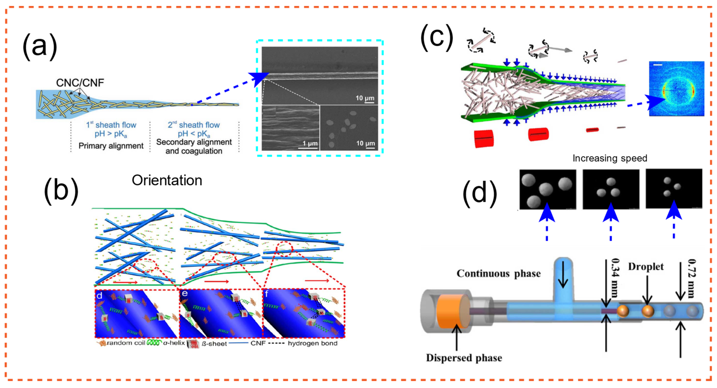
Figure 2.
Methods of patterning a PAD [178,179,180,181,182]: (a) 3D printing; Adapted from Ref. [178]. (b) wax printing; Adapted from Ref. [179]. (c) flexography printing; Adapted with permission from Ref. [181]. Copyright 2019 Elsevier. (d) cutting; Adapted with permission from Ref. [180]. Copyright 2015 Wiley-VCH. (e) photo-lithography; Adapted with permission from Ref. [180]. Copyright 2015 Wiley-VCH. (f) plotting; Adapted with permission from Ref. [182]. Copyright 2016 Springer-Verlag. These strategies are described in detail in the main text.
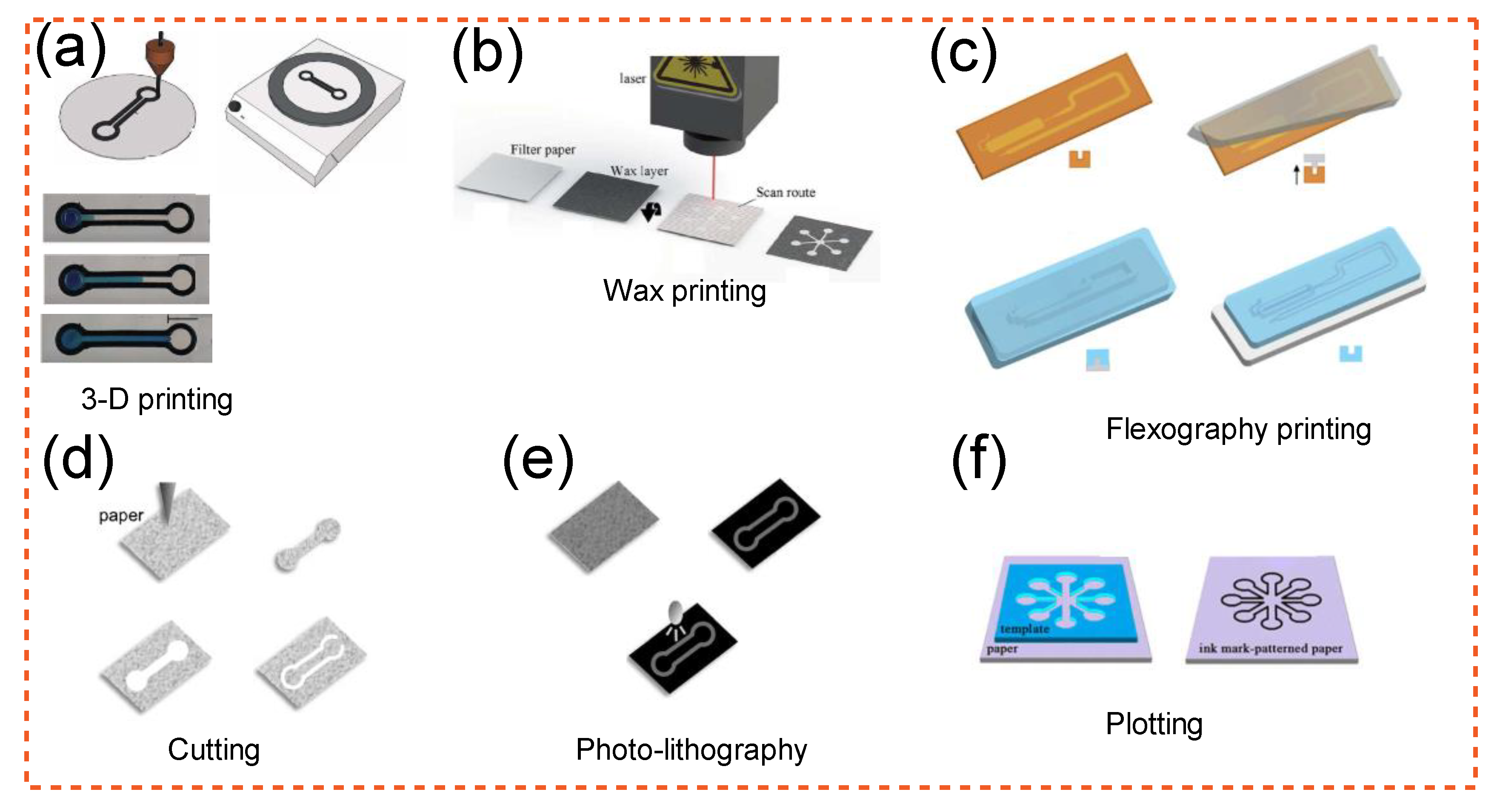
Figure 3.
(a) Photolithographic devices for measuring glucose and protein. Adapted with permission from Ref. [199]. Copyright 2010 American Chemical Society. (b) As a supporting material embedding for the microchannels, cellulose nanofibrils hydrogel, a 3D structuring ultrathin film, was employed. Adapted with permission from Ref. [226]. Copyright 2017 American Chemical Society. (c) The μPAD is divided into three parts: sensing (6.5 mm diameter), substrate (6.5 mm diameter), and water addition (11 mm diameter). The distance between the regions of addition of water and substrate was calculated to be 12 mm, while the area of sensing was estimated to be 11 mm. Adapted with permission from Ref. [206]. Copyright 2018 American Chemical Society. (d) Scanning electron microscopy (SEM) photos of white wood microchannels are shown, as well as high magnification SEM photographs of individual microchannels, to demonstrate the presence of pits with an average diameter of 2.5 μm in addition to obstructed mass transmission that these designs can offer. Adapted with permissions from Ref. [205]. Copyright 2018 American Chemical Society.
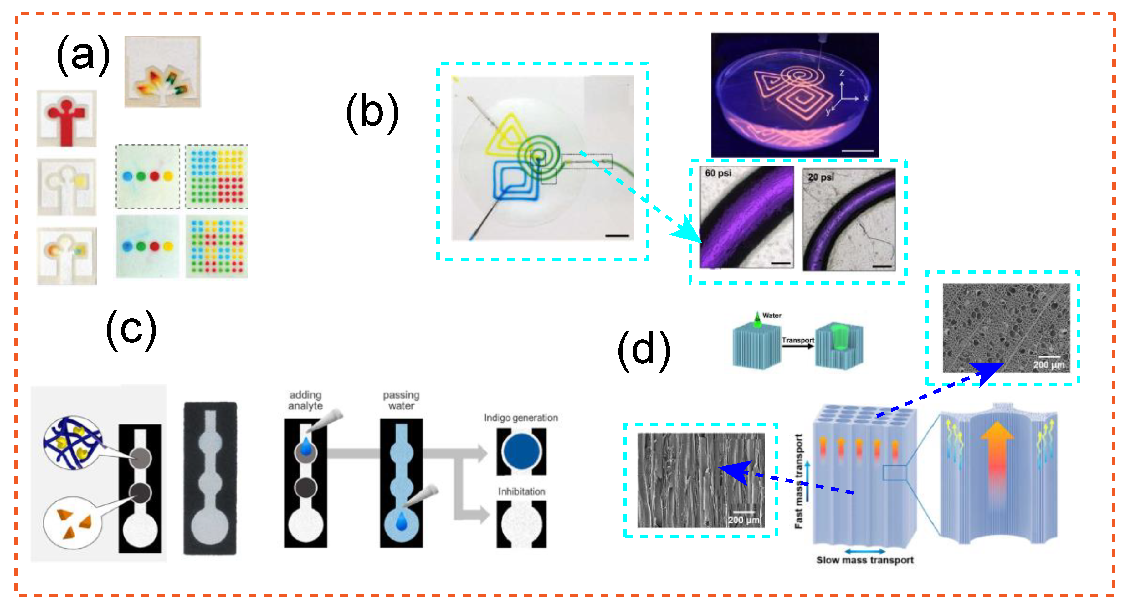
Figure 4.
(a) The effect of increasing CNF layers on surface density, moieties immobilization, enzymatic CNF release, and cell release. The dotted line represents the microchannel boundary. Changing the strength of the fluorescence reveals the density of the layers. The image shows a linear CNF/bacterial cellulose packed with fluorescent particles. In the picture at the bottom, yellow and blue liquids were injected independently. Adapted with permissions from Ref. [207]. Copyright 2020 Royal Society of Chemistry. (b) Under confocal lens for one week, oil cellulose-based microcapsules, marked with magenta with tracer with sizes of 0.5 μm that can freely find room to diffuse inside. Adapted with permissions from Ref. [92]. Copyright 2019 American Chemical Society. (c) The interaction of two sides of a bacterial cellulose film on cells and tissue can modify their behaviour. The findings of this study provide a new path for improving the wound healing efficiency of bacterial cellulose material. Adapted from Ref. [228]. (d) Relying on microfluidic chips for analysis, a stacked design (multilayered) electrostatic printing technology was perceived for producing CNF-based microfluidic chip for detecting water quality. This idea might be used to create a colorimetric platform that can quantitatively detect iron levels in water. Adapted from Ref. [160].
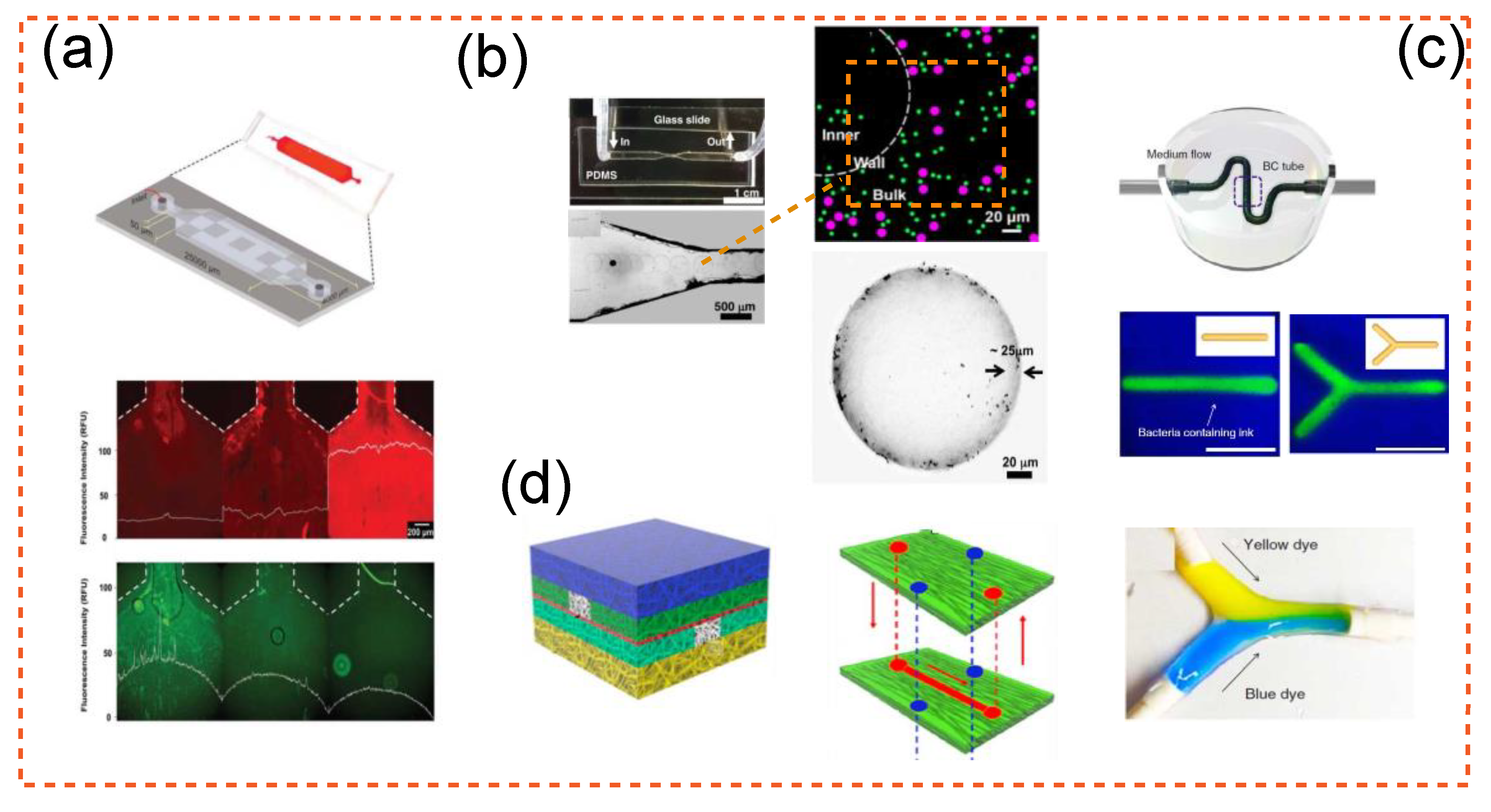
Figure 5.
Flow-focusing, co-flow and T-junction design in creating cellulose-based products. (a) Bacteria were encapsulated in a co-flow microfluidic device in which bacteria and media flow as a dispersed phase into continuous phase of 2.5% fibrillar HCO. Final products are shown at the top of co-flow design as dispersed emulsion droplets. Adapted with permission from Ref. [92]. Copyright 2019 American Chemical Society. (b) Images of phase split at micro impacting T-junctions. At the bottom, a sample of monodispersed droplets created by tuning the flow speeds of two streams is displayed. Adapted with permission from Ref. [95]. Copyright 2014 Elsevier. (c) CNF orientation in a flow-focusing design, for orientation of particles. The picture at the right is of a hydrodynamic flow concentrating zone stained with eosin/fluorescein at three distinct flow rates using similar design. Adapted with permissions from Refs. [89,93,94]. Copyright 2021 The Author(s), under exclusive licence to Springer Nature B.V.; 2020 Springer-Verlag GmbH Germany; 2020 American Chemical Society.
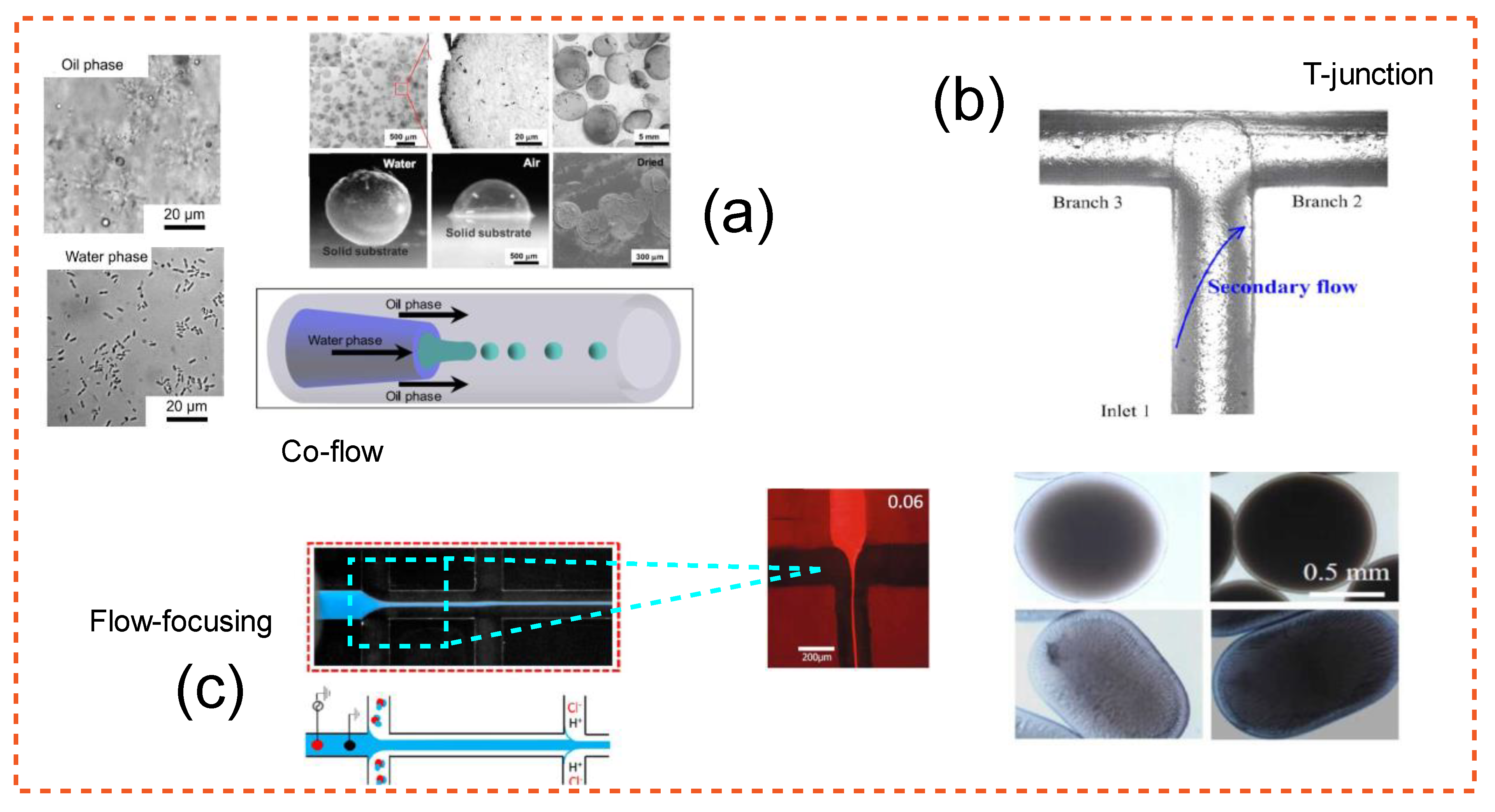
Figure 6.
Cellulosic-based designs were created with the help of microfluidics [107,151,259,260,261]. (a) Polarization of a micrograph depicting the production of cholesteric cellulose nanocrystals from oil in a water droplet. Swelling of microfluidic droplet-templated CNC microparticles (from 3 wt % CNC suspensions) when observed under polarized optical microscopy. Adapted with permission from Ref. [259]. Copyright 2016 American Chemical Society. (b) Pore network of a microfluidic device produced with PDMS using the micromolding process, with pillars and edges defining the flow channel and pore network clearly. Adapted with permission from Ref. [151]. Copyright 2015 American Chemical Society. (c) Dry sCNC microparticles display variable chiral nematic texturing due to the occurrence of kinetic arrest during drying, while chemically modified (and thus crosslinked) microparticles exhibited uniform radial ordering (the image at the right-bottom of (c). Adapted with permission from Ref. [260]. Copyright 2018 American Chemical Society. (d) Lipophilic molecule encapsulation inside oil small droplets or embedded emulsions might be used to encapsulate functional target chemicals. Adapted with permission from Ref. [261]. Copyright 2021 Elsevier. (e) Three-dimensional representation of a form-stable composite including CNF-shell-produced capsules. Adapted with permission from Ref. [107]. Copyright 2019 Elsevier.
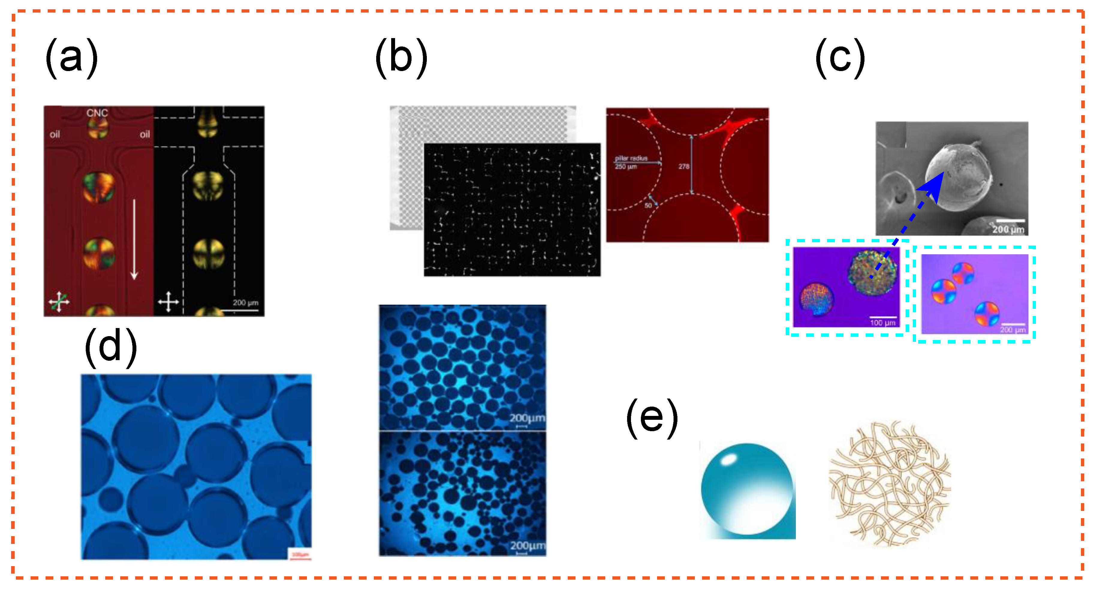
Figure 7.
(a) Droplets of the mineral oil and cholesteric CNC phases with various volume percentages. The row at the bottom displays variation in droplet morphology and related polarized optical microscopy of photos. This method may also be used to synthesize core–shell particles with a liquid crystalline shell. Adapted from Ref. [268]. (b) Spiraling tube to elongate the emulsion droplet before consolidation phase that makes the particle anisotropic. Particles with different aspect ratio synthesized using this approach. As the particles exited the tube, UV light was employed to rigidify them. Adapted with permissions from Ref. [269]. Copyright 2019 WILEY-VCH. (c) Two microfluidic device geometries to produce hydrogel particles and hydrogel Janus particles. The scheme on the left makes microbeads using a T-section design, whereas the diagram on the right is for flow focusing for production of Janus particles. Adapted from Ref. [270].

Figure 8.
Products manufactured with microfluidics derived from cellulose. (a) Three cellulose microcapsule deformation regimes: elastic deformation, mild compression, and finally stretching and folding. Adapted with permission from Ref. [92]. Copyright 2019 American Chemical Society. (b) Prepared cellulose capsules following isopropanol addition. Adapted with permission from Ref. [142]. Copyright 2014 The Royal Society of Chemistry. (c) The tissue of a microfluidic paper-based device is illustrated on the side under SEM. Adapted from Ref. [278]. (d) SEM pictures of CNF orientated within a microfluidics device (fibers are impregnated in an epoxy-based matrix). Adapted with permission from Ref. [109]. Copyright 2018 Wiley-VCH. (e) Images of buckled cellulose microcapsules under cross-polarizers and SEM images of particles. Adapted from Ref. [259]. (f) SEM pictograph of cellulose-based microcapsules, flow rates for the production of these microcapsules varied from 200 to 1200 μL/h. Adapted with permission from Ref. [96]. Copyright 2009 Elsevier.
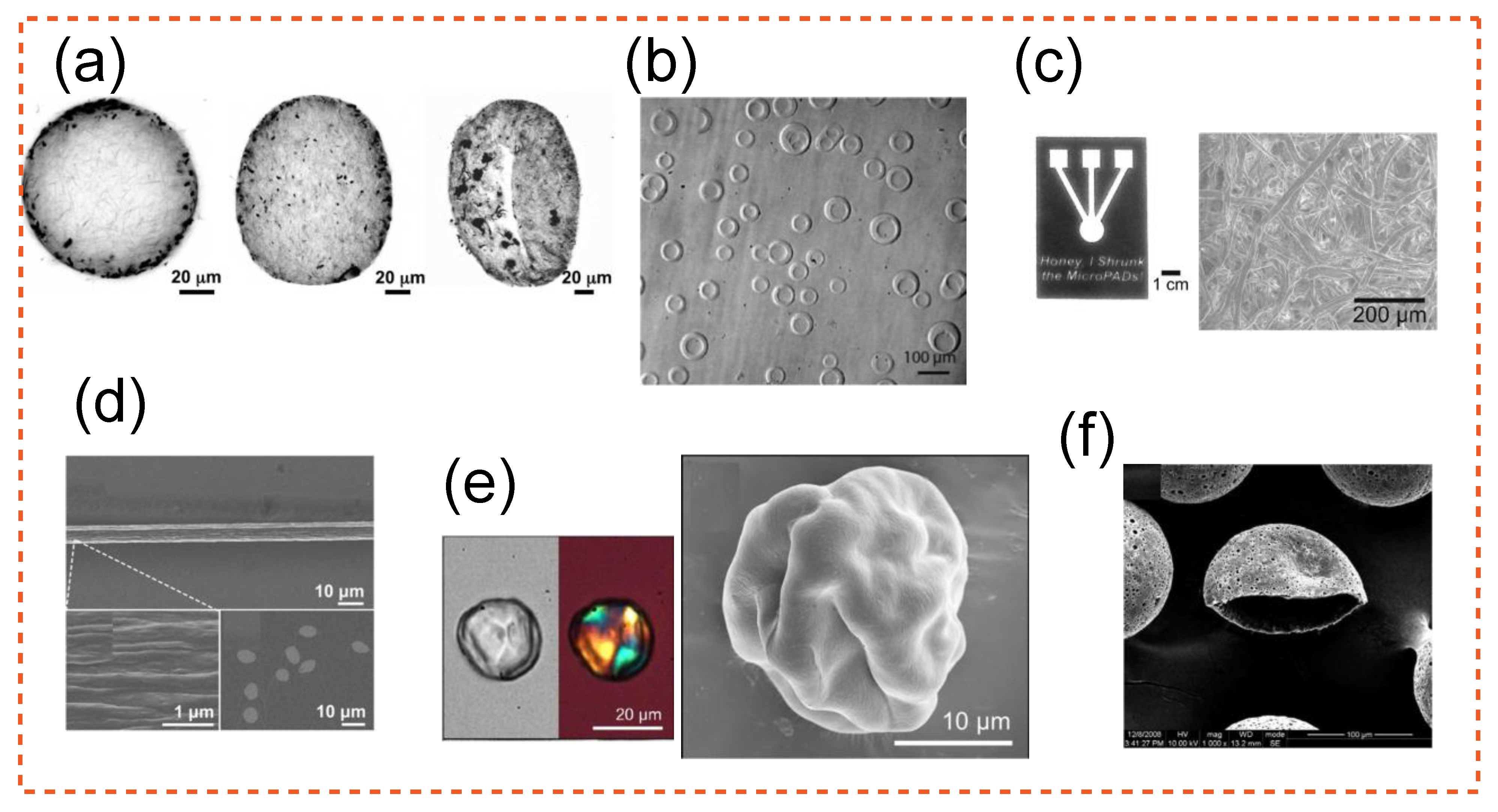

Table 1.
Presentation of research involving microfluidics in the creation of cellulose-based goods, as well as their highlights.
Table 1.
Presentation of research involving microfluidics in the creation of cellulose-based goods, as well as their highlights.
| Study | Application | Highlight |
|---|---|---|
| Baek and Park [89] | Creation of uniformly sized porous cellulose beads | The creation of the cell/N-methyl morpholine N-oxide droplet in the ethylene glycol solution in the T-junction microfluidic chip could not be observed in situ using an optical microscope. As a model study, the form of a cellulose bead after coagulation was explored. |
| Pepicelli et al. [131] | Creation of cellulose-based biodegradable microcapsules. | Gluconacetobacter xylinus may live and flourish in a variety of environments. Cellulose is a major constituent of these self-secreted protective coatings (made with Gluconacetobacter xylinus). The results achieved mark the first step toward the fabrication of self-assembled degradable cellulose capsule. |
| Duong et al. [132] | Cellulose fiber membrane was sandwiched between two silicone elastomer poly(dimethylsiloxane) (PDMS) layers to mimic BBB | In vitro, a microfluidic system was created to replicate the human blood–brain barrier (BBB). BBB formation was assessed using cell survival, actin filament (F-actin) formation, and transepithelial electrical resistance (TEER). Overall, the model showed a simple to duplicate and low-cost framework for in vitro drug test. |
| Jayapiriya and Goel [133] | Creation of paper-based energy harvesting device | Using E. coli as the biocatalyst, a paper fuel cell can generate 11.8 W·cm−2 of electricity. Fuel cell construction that is both cost-effective and thrifty can be utilized to power a wide range of low-power point-of-care devices. |
| Sharratt et al. [134] | Creation of hydrogel microparticles | Hydrogel microparticles (HMPs) have a wide range of practical uses, from medication delivery to tissue development. The kinetics of gelation fronts are initially determined using 1D microfluidic studies. The effective diffusive coefficients rise with Fe3+ content and drop with NaCMC concentration. |
| Chen et al. [135] | Creation of core–shell microparticles | Polysaccharides have been shown to be useful in medication encapsulation and delivery. Authors offered a multicompartment polysaccharide core–shell microparticle that may be used to build a long-lasting dual-release system of active molecules for wound healing. Microparticles reduced inflammation while also promoting granulation tissue development, collagen deposition, and angiogenesis. |
| Liu et al. [96] | Creation of monodisperse ethyl cellulose (EC) hollow microcapsules | A simple and new approach is used to effectively create monodisperse ethyl cellulose hollow microcapsules. Microfluidic double emulsification and solvent diffusion are used in this method. Microcapsules manufactured in an iso-osmotic environment have a flawless spherical form and no collapse. |
| Li et al. [136] | Using bacterial cellulose for wound healing | Bacterial cellulose is a type of nano-biomaterial that may be used in tissue engineering. It is unknown how bacterial cellulose’s nanoscale structure impacts skin wound healing. The lower portion of bacterial cellulose film can encourage cell migration to aid in wound healing. |
| Zhao et al. [137] | Creation of cellulose-based flexible electronics | Cellulose is a natural biopolymer with several benefits such as low cost, ease of processing, and degradability. It is extensively used in flexible electronics as a substrate, dielectric material, gel electrolyte, and derived carbon-made material. |
| Mahapatra et al. [138] | Creation of cellulose-based sensing devices | For its unique features, including biocompatibility, cellulose has the potential to be used in the creation of cytosensors, and organisms in a variety of materials. |
| Del Giudice et al. [139] | Assessing morphological structure of hydroxyethyl cellulose with microfluidics | Non-modified hydroxyethyl cellulose acts as a linear uncharged polymer when dissolved in water, with an entangled mass concentration of 0.3 wt%. For the first time, authors presented the concentrations scaling for hydroxy ethyl cellulose solutions with the longest relaxation period. |
| Zeng et al. [140] | CNFs produced by microfluidic homogenization | The purpose of this research was to investigate and compare the shape and rheology of cellulose nanofibrils derived from bleached softwood kraft pulp. CNFs had the greatest viscous, bulk modulus, and loss modulus, as well as the largest aspect ratio. |
| Wang et al. [141] | Creation of uniform size CNCs via microfluidic technology | CNC is a novel form of molecular substance derived from biomass. CNCs with a good dividend and consistency were achieved by hydrolysis process in a microfluidic system using a 60% sulfuric acid solution at 35 °C for 40 min. |
| Lari et al. [93] | Creation of poly(ε-caprolactone) and cellulose acetate nanoparticles | The purpose of this study was to compare two types of microfluidic-assisted nanoparticles (NPs) based on poly(-caprolactone) (PCL) and cellulose acetate (CA). It was discovered that CA NPs had a smaller average diameter (37 nm) and a lower polydispersity index (PDI) (0.035) than PCL NPs. |
| Carrick et al. [142] | Creation of cellulose capsules | For medication delivery or controlled release capsules, cellulose capsules with a limited size distribution might be advantageous. Capsules were carboxymethylated to make them pH responsive and to expand roughly 10% when the pH was changed from 3 to 10. |
| Pei et al. [143] | Cross-linked cellulose hydrogel was used for making a chip | To create cellulose–collagen hybrid hydrogels, collagen, a critical extracellular component for cell culture, was cross-linked in the cellulose hydrogel. Researchers revealed that they have excellent structural reproduction ability, physical qualities, and cell culture cytocompatibility. |
| Zhang et al. [144] | Creation of a technology for adsorption and isolation of nucleic acids on cellulose magnetic beads | The use of a 3D-printed microfluidic chip enables the extraction of nucleic acids without the need of vortexes or centrifuges. Magnetic, interfacial, and viscous drag forces are described inside the chip’s microgeometries. Across a variety of HPV plasmid levels, an overall extraction efficiency of 61% is reported. |
| Wenzlik et al. [145] | In a microfluidic setting, cholesteric particles were made from cellulose derivatives | Co-flowing injection of drops of liquid crystalline mixes of cellulose derivatives into microspheres on the micrometre scale is used in the process. |
| Miyashita et al. [146] | The diamagnetic director for microfluidic systems is made up of microcrystal-like cellulose fibrils | Cellulose is a potential material for the development of biogenic optical systems that imitate the unique optical capabilities of living creatures. In a microfluidic laboratory, magnetic orientation tests on microcrystalline cellulose were performed. During the dispersed light intensity process, light intensity altered depending on the direction of the magnetic field. |
| Chen et al. [147] | A multilayer microfluidic device with a PDMS–cellulose composite film was developed | This paper describes an integrated multilayer microfluidic system that can pre-treat raw samples and detect them using immunoassays. Using the crossflow concept, a polydimethylsiloxane (PDMS)-cellulose composite film was employed to extract plasma from raw samples. |
| Włodarczyk and Zarzycki [148] | On silica and cellulose micro-TLC plates, the chromatographic behaviour of chosen colours was studied | The chromatographic behaviour of 18 colourants, including amaranth, black PN, bromophenol blue, and bromocresol green, was investigated. Data were gathered using silica and cellulose-coated microplates under thermostatic settings (303 K). Dyes are frequently utilized as colourants in food and industry, as well as sensing compounds in analytical and medicinal purposes. |
| Ghorbani et al. [149] | Creation of CNF- stabilized perfluoro droplets | In a variety of applications, hydrodynamic cavitation on microchips has been emphasised. Cavitating flow patterns may be used to promote a wide range of industrial and technical applications. Inside microfluidic devices, a novel technique involving cellulose nanocomposites perfluoro droplets was tested. |
| Park et al. [150] | Wet-spun microcomposite filaments were made with cellulose | To make microfilaments, cellulose nanocrystals were wet spun in a coagulation bath. The influence of sodium alginate on the characteristics of the micro composite filament was studied. The higher spinning rate of sodium alginate generated a rise in the alignment index of CNCs, leading to an improvement in the material’s tensile characteristics. |
| Grate et al. [151] | Creation of Alexa Fluor-labeled fluorescent CNCs | A group of researchers discovered a mechanism to attach Alexa Fluor dyes to cellulose nanocrystals while preserving the nanocrystal’s overall structure. Bioimaging tests revealed that the spatial positioning of solid cellulose deposits could be detected and their elimination over time under the action of Celluclast® enzymes or microorganisms could be monitored. |
| Ke et al. [152] | Microgels made from carboxymethyl cellulose for cell encapsulation | Carboxy methyl cellulose was modified with 4-hydroxybenzylamine (CMC-Ph) to create carboxy methyl cellulose-based microgels for use in scaffolds. The ATDC5 chondrocytic cell line was grown for up to 40 days after being encased in carboxy methyl cellulose microgels. |
| Rao et al. [153] | Creation of microfluidic paper fuel cell | MMPFCs (Membraneless Microfluidic Paper Fuel Cells) are promising technologies for harvesting energy for a variety of portable applications. Because of the built-in co-laminar flow and integrated capillary, the devices remove the need for membranes and additional pumps. |
| Shen et al. [154] | Creation of paper-based microfluidic fuel cells | Microfluidic fuel cells made of paper are emerging as possible renewable energy sources for small-scale electronic systems. The textural qualities of the paper channels have a considerable impact on the performance of paper fuel cells. The use of paper with a bigger mean pore width may result in a greater peak power density and open circuit voltage. |
| Shefa et al. [155] | A method of incorporation of curcumin (Cur) into a hydrogel system based on cellulose was developed | A freeze–thaw technique was used to create a Cur including physically crosslinked TEMPO-oxidized CNC–polyvinyl–alcohol curcumin– hydrogel, that produced curcumin to speed wound healing. L929 fibroblast cells incorporated curcumin within 4 h of incubation, according to in vitro experiments. |
| Chen et al. [156] | Separation of glycoproteins was achieved using bacterial cellulose microfluidic column | A simple technique was used to produce a regenerated bacterial cellulose column containing concanavalin A (Con A) lectin immobilised in a microfluidic device to evaluate and separate glycoproteins. Schiff-base formation was used to covalently link lectin Con A to the RBC matrix surface. |
Table 2.
Presentation of research in which cellulose was employed as a chip-building material.
| Study | Highlights |
|---|---|
| Lin et al. [198] | Three-dimensional microfluidic paper-based analytical devices (3D-µPADs) are a potential platform technology that enables for complicated fluid manipulation, parallel sample distribution, high throughput, and multiplex analysis assays. This technology can regulate the penetration depth of melted wax printed on both sides of a paper substrate, resulting in multilayer patterned channels in the substrate. |
| Martinez et al. [199] | A novel family of point-of-care diagnostic devices is PADs. They are affordable, simple to operate, and particularly developed for usage in poor nations. When completely developed, they may deliver faster and less expensive bioanalyses. |
| Yamada et al. [200] | On microfluidic PADs, “distance-based” detection patterns provide quantitative analysis without the need of signal output tools. Quantitative analysis is enabled by the distance-based quantified signal and the strong batch-to-batch production repeatability based on printing processes. |
| Li and Liu [201] | A wax-printing process is used to create 3D microfluidic channels inside a single sheet of cellulose paper. It enabled the production of up to four layers of paper channels in a 315-micrometer-thick substrate surface without the need for process optimization. |
| Ardalan et al. [202] | The smart wearable sweat patch (SWSP) is a non-invasive and in situ multi-sensing sweat biomarkers sensor that measures glucose, lactate, pH, chloride, and volume. A smartphone app was also created to use a detection algorithm to estimate the quantity of biomarkers. |
| Arun et al. [203] | The capillary-driven fluid flow of a combination of fuel and electrolyte drives the capillary-driven fluid flow of a microfluidic fuel cell. Various pencils are used to produce the graphite electrodes to study their influence on fuel cell performance. To improve performance, the paper fuel cell was also manufactured in different diameters and coupled as cell stacks. |
| Yan et al. [157] | H2O2 is used as both fuel and oxidant in a paper-based microfluidic fuel cell for portable electronics. It does have a peak energy capacity of 0.88 mW·cm−2. The fuel cell does not require precious-metal catalysts, and the fuel utilized is carbon free and environmentally friendly. |
| del Torno-de Román et al. [204] | The power and output current of a paper-based enzyme glucose/O2 fuel cell can be enhanced by adopting a quasi-steady flow. The fuel cell’s anode and cathode are composed of display carbon electrodes that have been correctly functionalized with protease inks. |
| Jia et al. [205] | Because of its hydrophilic properties, cellulose paper has been widely employed in microfluidic devices. Cellulose is placed in paper at random, with no specific direction or pathways. White wood possesses natural microchannels as well as a quick and anisotropic liquid and big solid particle movement. |
| Cai et al. [90] | By silanizing filter cellulose using a paper mask, authors created a new, low-cost, and straightforward approach for fabricating PADs. This procedure requires no expensive equipment and may be carried out by inexperienced persons. |
| Murase et al. [206] | Cellulose nanofiber can be utilized as a component in PADs. The thixotropic characteristic of TEMPO-oxidized CNCs aqueous dispersion allowed for inkjet printability, which aided manufacturing. |
| Kumar et al. [207] | Cancer diagnostics are not currently prioritised in resource-limited settings. However, budget-friendly and targeted screening test and diagnostic tools are in great need. Multi-layer cellulose nanofibril-based coverings on expendable microfluidics were tuned for targeted capture and efficient release of target cells. |
| Choi et al. [208] | The microfluidic cellulose microfibre chip was prototyped by injecting 10 percent CM solutions onto CNC-milled substrates. It can identify exudative age-related macular degeneration in human aqueous sense organs. |
| Fu and Liu [209] | PADs are typically mounted on a cellulose paper substrate. Covalent bonds with the target biomolecule can be achieved by modifying chemicals. The optimum performance for biosensing applications comes from potassium periodate (KIO4)-modified cellulose paper. |
| Lu et al. [114] | Spider silks have amazing mechanical qualities; hence, one of the areas of research in biomimetic fibres was the construction of structures with high silk fibres as optical waveguides. The fibres might be useful in biological media, bio photonics, and central nervous system interfaces. |
| Bao et al. [210] | Transistors built of van der Waals materials are allowed by an all-cellulose paper with CNF on the upper surface, which results in outstanding surface roughness and electrolyte absorption. These planar transistors can be employed as sensors in PADs, together with other components. |
| Yadav et al. [211] | Microfluidics has the potential to revolutionise point-of-care detection in smart healthcare. Paper as a substrate aids in reducing existing stiff wastes and inevitable pollution. Flexible microfluidic technology hardcopy provides a low-cost technical foundation for next-generation intelligent sensors. |
| Solin et al. [212] | Point-of-care diagnosis can benefit from microfluidic technologies. Authors looked at the fluidic structure due to stencil painting on flexible surfaces. Combining minerals with cellulose fibrils resulted in optimal printability and flow profiles. The findings demonstrate the use of these pathways for drug and chemical analysis. |
Table 3.
Refs. classified based on nanocellulose types involved and application in conjunction with microfluidics.
Table 3.
Refs. classified based on nanocellulose types involved and application in conjunction with microfluidics.
| Study | Material Used | Microfluidic Application |
|---|---|---|
| Shin and Hyun [226] | CNF | Construction material for microfluidics |
| Li and Liu [201] | CNF | Construction material for microfluidics |
| Jia et al. [205] | CNF | Construction material for microfluidics |
| Cai et al. [90] | Filter paper | Construction material for microfluidics, glucose assay |
| Yu et al. [271] | Bacterial cellulose | Production of cellulose microcapsules, wound healing |
| Nechyporchuk et al. [109] | CNF, CNC | Using microfluidics for spinning strong microfibers |
| Li et al. [136] | Bacterial cellulose | Microfluidics as a platform to examine wound dressing screening |
| Ardalan et al. [202] | Cotton thread | Cellulose-based microfluidic wearable patch |
| Tata Rao et al. [272] | Cellulose absorbent pads | Microfluidic paper–based fuel cells |
| Park et al. [273] | Bacterial cellulose | Cell culture and wound healing |
| Baek and Park [89] | Molten cellulose | Microfluidic set up was used to produce cellulose beads |
| Higashi and Miki [257] | Bacterial cellulose | Application for biochemical engineering and cell delivery systems |
| Song et al. [92] | Bacterial cellulose | Produce a framework for artificial cells |
| Pepicelli et al. [131] | Bacterial cellulose | Capsules for applications such as flavor, fragrance, agrochemicals, nutrients, and drug encapsulation |
| Zhang et al. [107] | Cellulose acetate | Remediation of water |
| Liu et al. [274] | Carboxy methyl cellulose | Preparing cell-laden microgels |
| Levin et al. [260] | CNCs | Porous microparticles for applications such as drug delivery or sorption agents. |
| Kaufman et al. [275] | CNF | Production of strong yet flexible microcapsule shells. |
| Dhand et al. [276] | TEMPO-oxidized CNF | Tune microparticles suspension to tailor complex fluid rheology |
| Carrick et al. [142] | cellulose pulp | Microencapsulation for drug delivery or controlled release capsules. |
| Yeap et al. [16] | Ethyl cellulose | Drug–excipient composite microparticles |
| Yeap et al. [277] | Ethyl cellulose | Production of monodisperse spherical drug particles |
Publisher’s Note: MDPI stays neutral with regard to jurisdictional claims in published maps and institutional affiliations. |
© 2022 by the author. Licensee MDPI, Basel, Switzerland. This article is an open access article distributed under the terms and conditions of the Creative Commons Attribution (CC BY) license (https://creativecommons.org/licenses/by/4.0/).
Share and Cite
MDPI and ACS Style
Abbasi Moud, A. Cellulose through the Lens of Microfluidics: A Review. Appl. Biosci. 2022, 1, 1-37. https://doi.org/10.3390/applbiosci1010001
AMA Style
Abbasi Moud A. Cellulose through the Lens of Microfluidics: A Review. Applied Biosciences. 2022; 1(1):1-37. https://doi.org/10.3390/applbiosci1010001
Chicago/Turabian StyleAbbasi Moud, Aref. 2022. "Cellulose through the Lens of Microfluidics: A Review" Applied Biosciences 1, no. 1: 1-37. https://doi.org/10.3390/applbiosci1010001