
A Simple Model to Predict Loads within Muscle-Tendon Complexes of the Shoulder during Fast Motions


Abstract
:1. Introduction
2. Material and Methods
2.1. Overview
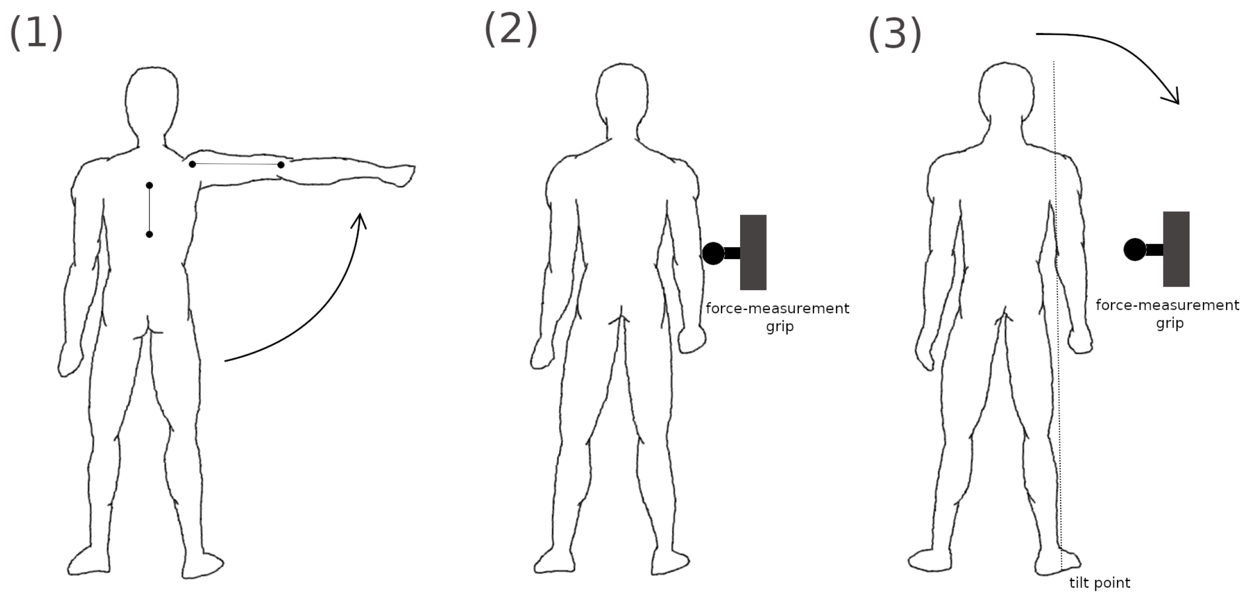
2.2. Experiments
2.3. Shoulder Model
3. Results
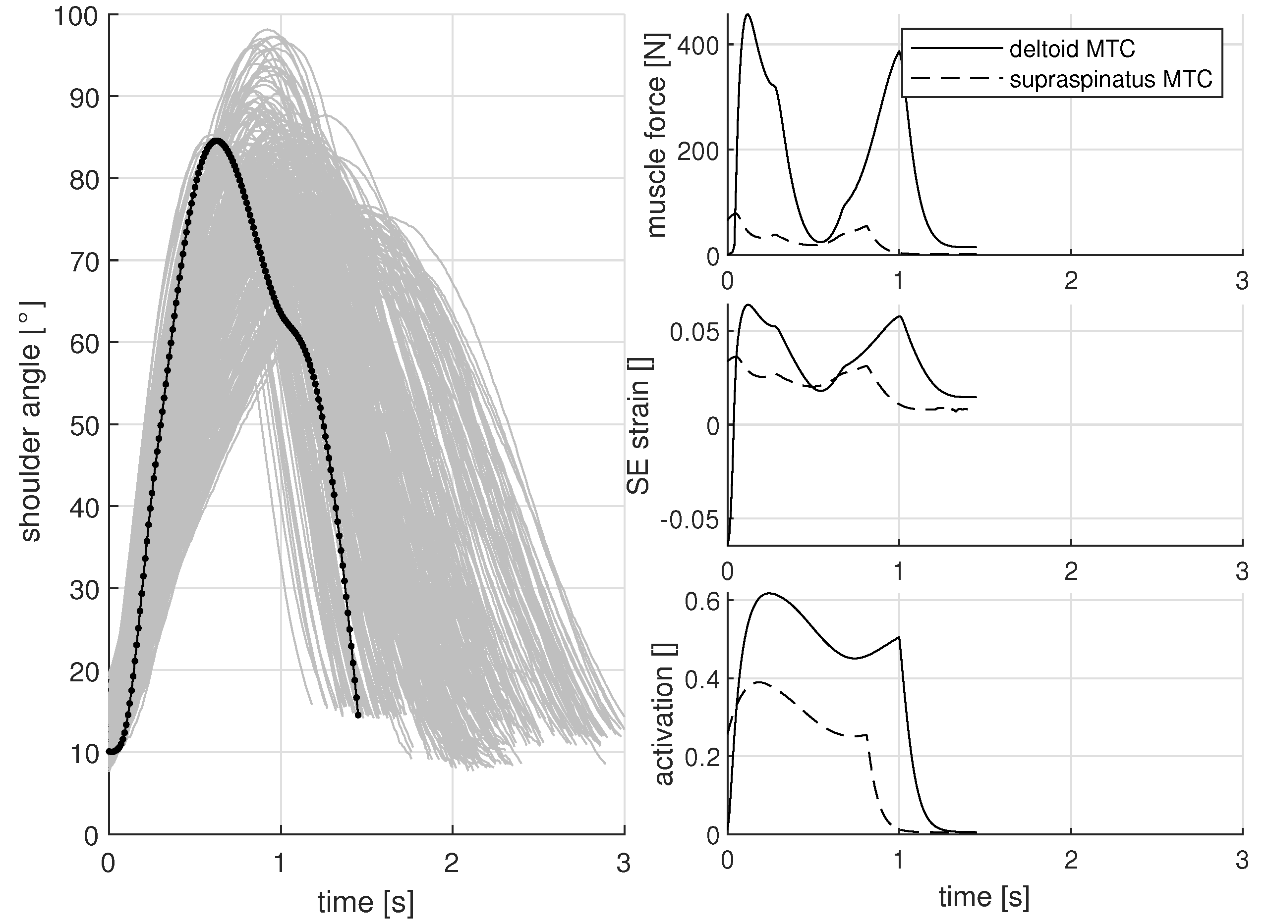
3.1. Shoulder Angle While Lifting a Low Load
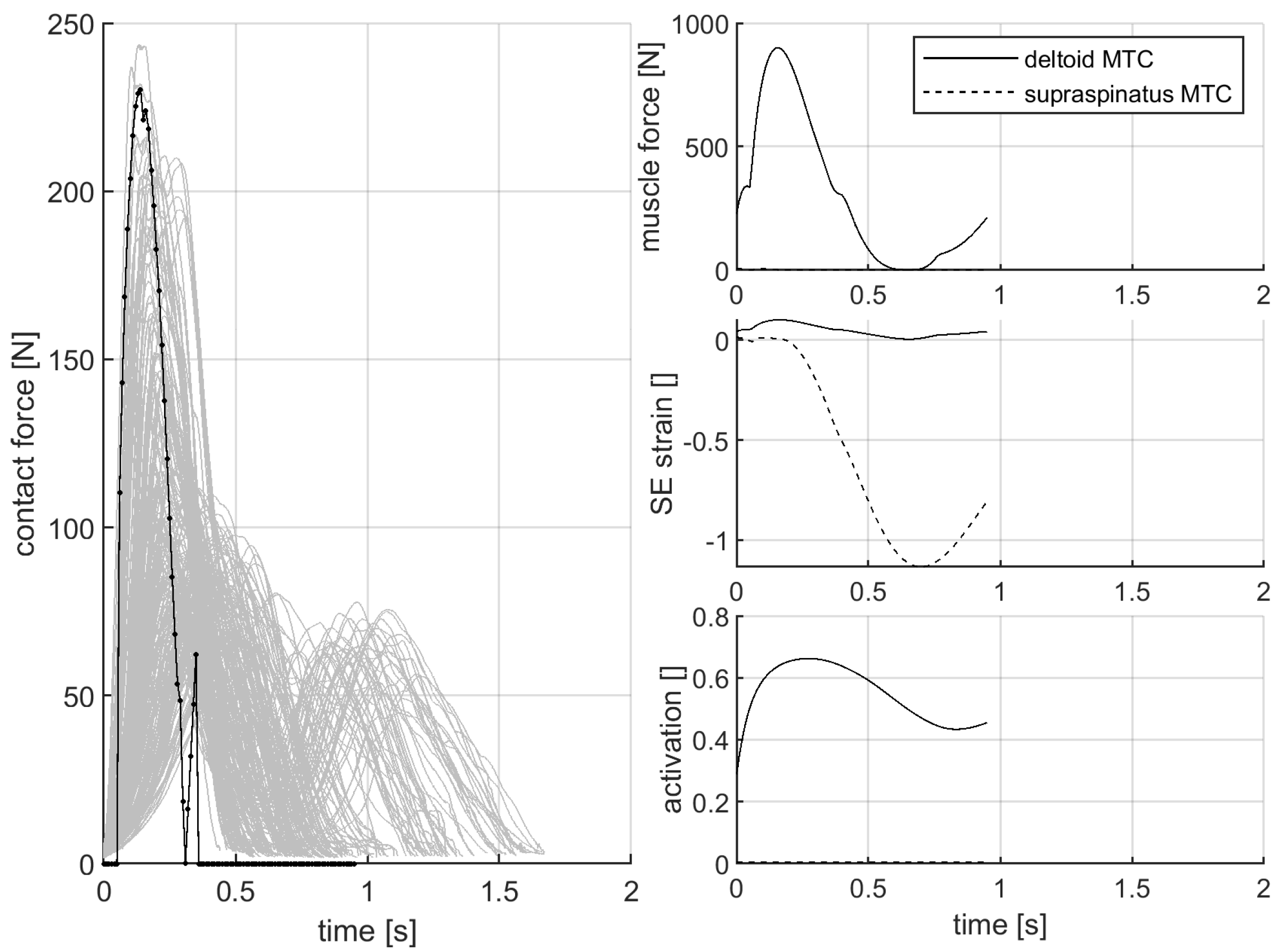
3.2. Contact Force While Pushing the Force-Measurement Device
3.3. Contact Force during the Gentle Side Fall against the Force-Measurement Device
4. Discussion
4.1. Simple Hatze-Based Activation for the Simulation of Fast Motions
4.2. Mechanical Constraints as an Explanation for Tendon Damage
4.3. Muscle Force Generation and Limiting Degenerative Factors
4.4. Limitations of This Simulation Study
4.5. Conclusions
Author Contributions
Funding
Institutional Review Board Statement
Informed Consent Statement
Data Availability Statement
Acknowledgments
Conflicts of Interest
References
- Quental, C.; Folgado, J.; Ambrósio, J.; Monteiro, J. A multibody biomechanical model of the upper limb including the shoulder girdle. Multibody Syst. Dyn. 2012, 28, 83–108. [Google Scholar] [CrossRef]
- Clark, J.M.; Harryman, D.T. Tendons, ligaments, and capsule of the rotator cuff. Gross and microscopic anatomy. J. Bone Jt. Surgery. Am. Vol. 1992, 74, 713–725. [Google Scholar] [CrossRef]
- Lake, S.P.; Miller, K.S.; Elliott, D.M.; Soslowsky, L.J. Effect of fiber distribution and realignment on the nonlinear and inhomogeneous mechanical properties of human supraspinatus tendon under longitudinal tensile loading. J. Orthop. Res. 2009, 27, 1596–1602. [Google Scholar] [CrossRef] [PubMed] [Green Version]
- Lake, S.P.; Miller, K.S.; Elliott, D.M.; Soslowsky, L.J. Tensile properties and fiber alignment of human supraspinatus tendon in the transverse direction demonstrate inhomogeneity, nonlinearity, and regional isotropy. J. Biomech. 2010, 43, 727–732. [Google Scholar] [CrossRef] [PubMed] [Green Version]
- Lee, S.B.; Nakajima, T.; Luo, Z.P.; Zobitz, M.E.; Chang, Y.W.; An, K.N. The bursal and articular sides of the supraspinatus tendon have a different compressive stiffness. Clin. Biomech. 2000, 15, 241–247. [Google Scholar] [CrossRef]
- Itoi, E.; Berglund, L.J.; Grabowski, J.J.; Schultz, F.M.; Growney, E.S.; Morrey, B.F.; An, K.N. Tensile properties of the supraspinatus tendon. J. Orthop. Res. 1995, 13, 578–584. [Google Scholar] [CrossRef]
- Huang, C.Y.; Wang, V.M.; Pawluk, R.J.; Bucchieri, J.S.; Levine, W.N.; Bigliani, L.U.; Mow, V.C.; Flatow, E.L. Inhomogeneous mechanical behavior of the human supraspinatus tendon under uniaxial loading. J. Orthop. Res. 2005, 23, 924–930. [Google Scholar] [CrossRef] [PubMed]
- Barber, F.A.; Herbert, M.A.; Boothby, M.H. Ultimate tensile failure loads of a human dermal allograft rotator cuff augmentation. Arthroscopy 2008, 24, 20–24. [Google Scholar] [CrossRef] [PubMed]
- Bassett, R.W.; Browne, A.O.; Morrey, B.F.; An, K.N. Glenohumeral muscle force and moment mechanics in a position of shoulder instability. J. Biomech. 1990, 23, 405–415. [Google Scholar] [CrossRef]
- Seki, N.; Itoi, E.; Shibuya, Y.; Wakabayashi, I.; Sano, H.; Sashi, R.; Minagawa, H.; Yamamoto, N.; Abe, H.; Kikuchi, K.; et al. Mechanical environment of the supraspinatus tendon: Three-dimensional finite element model analysis. J. Orthop. Sci. 2008, 13, 348–353. [Google Scholar] [CrossRef]
- Sano, H.; Wakabayashi, I.; Itoi, E. Stress distribution in the supraspinatus tendon with partial-thickness tears: An analysis using two-dimensional finite element model. J. Shoulder Elb. Surg. 2006, 15, 100–105. [Google Scholar] [CrossRef] [PubMed]
- Wakabayashi, I.; Itoi, E.; Sano, H.; Shibuya, Y.; Sashi, R.; Minagawa, H.; Kobayashi, M. Mechanical environment of the supraspinatus tendon: A two-dimensional finite element model analysis. J. Shoulder Elb. Surg. 2003, 12, 612–617. [Google Scholar] [CrossRef]
- Schouten, A.C.; de Vlugt, E.; van der Helm, F.C.; Brouwn, G.G. Optimal posture control of a musculo-skeletal arm model. Biol. Cybern. 2001, 84, 143–152. [Google Scholar] [CrossRef] [PubMed]
- Nikooyan, A.A.; Veeger, H.E.J.; Westerhoff, P.; Graichen, F.; Bergmann, G.; van der Helm, F.C.T. Validation of the Delft Shoulder and Elbow Model using in-vivo glenohumeral joint contact forces. J. Biomech. 2010, 43, 3007–3014. [Google Scholar] [CrossRef] [PubMed]
- Bolsterlee, B.; Veeger, H.E.J.; van der Helm, F.C.T. Modelling clavicular and scapular kinematics: From measurement to simulation. Med. Biol. Eng. Comput. 2014, 52, 283–291. [Google Scholar] [CrossRef] [PubMed]
- Nikooyan, A.A.; Veeger, H.E.J.; Chadwick, E.K.J.; Praagman, M.; van der Helm, F.C.T. Development of a comprehensive musculoskeletal model of the shoulder and elbow. Med. Biol. Eng. Comput. 2011, 49, 1425–1435. [Google Scholar] [CrossRef] [PubMed] [Green Version]
- Haeufle, D.F.B.; Günther, M.; Bayer, A.; Schmitt, S. Hill-type muscle model with serial damping and eccentric force-velocity relation. J. Biomech. 2014, 47, 1531–1536. [Google Scholar] [CrossRef]
- Rode, C.; Siebert, T.; Herzog, W.; Blickhan, R. The effects of parallel and series elastic components on the active cat soleus force-length relationship. J. Mech. Med. Biol. 2009, 9, 105–122. [Google Scholar] [CrossRef]
- Mörl, F.; Siebert, T.; Häufle, D. Contraction dynamics and function of the muscle-tendon complex depend on the muscle fibre-tendon length ratio: A simulation study. Biomech. Model Mechanobiol. 2015, 15, 245–258. [Google Scholar] [CrossRef]
- Rockenfeller, R.; Günther, M. Hill equation and Hatze’s muscle activation dynamics complement each other: Enhanced pharmacological and physiological interpretability of modelled activity-pCa curves. J. Theor. Biol. 2017, 431, 11–24. [Google Scholar] [CrossRef]
- Rockenfeller, R.; Günther, M.; Stutzig, N.; Haeufle, D.F.B.; Siebert, T.; Schmitt, S.; Leichsenring, K.; Böl, M.; Götz, T. Exhaustion of skeletal muscle fibers within seconds: Incorporating phosphate kinetics into a Hill-type model. Front. Physiol. 2020, 11, 306. [Google Scholar] [CrossRef] [PubMed]
- Siebert, T.; Stutzig, N.; Rode, C. A hill-type muscle model expansion accounting for effects of varying transverse muscle load. J. Biomech. 2018, 66, 57–62. [Google Scholar] [CrossRef] [PubMed]
- NASA. Man-Systems Integration Standards, Anthropometry and Biomechanics; Technical Report; National Aeronautics and Space Administration: Washington, DC, USA, 2000. [Google Scholar]
- Günther, M.; Schmitt, S.; Wank, V. High-frequency oscillations as a consequence of neglected serial damping in Hill-type muscle models. Biol. Cybern. 2007, 97, 63–79. [Google Scholar] [CrossRef] [PubMed]
- Siebert, T.; Rode, C.; Herzog, W.; Till, O.; Blickhan, R. Nonlinearities make a difference: Comparison of two common Hill-type models with real muscle. Biol. Cybern. 2008, 98, 133–143. [Google Scholar] [CrossRef] [PubMed]
- Mörl, F.; Siebert, T.; Schmitt, S.; Blickhan, R.; Günther, M. Electro-mechanical delay in Hill-type muscle models. J. Mech. Med. Biol. 2012, 12, 1250085. [Google Scholar] [CrossRef]
- Van der Helm, F.C.; Veeger, H.E.; Pronk, G.M.; Van der Woude, L.H.; Rozendal, R.H. Geometry parameters for musculoskeletal modelling of the shoulder system. J. Biomech. 1992, 25, 129–144. [Google Scholar] [CrossRef]
- Kleinau, J. Modellierung des Mechanischen Bewegungsablaufs in Einem Arm bei Anlegen von Vibrationen Sowie Experimentelle Anpassung der Modellparameter. Master’s Thesis, Eberhard-Karls-Universität Tübingen, Tübingen, Germany, 1993. [Google Scholar]
- Hatze, H. Myocybernetic Control Models of Skeletal Muscle—Characteristics and Applications; University of South Africa Press: Pretoria, South Africa, 1981. [Google Scholar]
- Rockenfeller, R.; Günther, M. Inter-filament spacing mediates calcium binding to troponin: A simple geometric-mechanistic model explains the shift of force-length maxima with muscle activation. J. Theor. Biol. 2018, 454, 240–252. [Google Scholar] [CrossRef] [PubMed]
- Rockenfeller, R.; Günther, M. Extracting low-velocity concentric and eccentric dynamic muscle properties from isometric contraction experiments. Math. Biosci. 2016, 278, 77–93. [Google Scholar] [CrossRef] [PubMed]
- Rockenfeller, R.; Günther, M.; Schmitt, S.; Götz, T. Comparative sensitivity analysis of muscle activation dynamics. Comput. Math. Methods Med. 2015, 4, 1–16. [Google Scholar] [CrossRef] [Green Version]
- Biewener, A.A.; Wakeling, J.M.; Lee, S.S.; Arnold, A.S. Validation of Hill-type muscle models in relation to neuromuscular recruitment and force-velocity properties: Predicting patterns of in vivo muscle force. Integr. Comp. Biol. 2014, 54, 1072–1083. [Google Scholar] [CrossRef] [Green Version]
- Dick, T.J.M.; Biewener, A.A.; Wakeling, J.M. Comparison of human gastrocnemius forces predicted by Hill-type muscle models and estimated from ultrasound images. J. Exp. Biol. 2017. [Google Scholar] [CrossRef] [PubMed] [Green Version]
- Wakeling, J.M.; Uehli, K.; Rozitis, A.I. Muscle fibre recruitment can respond to the mechanics of the muscle contraction. J. R. Soc. Interface 2006, 3, 533–544. [Google Scholar] [CrossRef] [PubMed]
- Günther, M.; Ruder, H. Synthesis of two-dimensional human walking: A test of the lambda-model. Biol. Cybern. 2003, 89, 89–106. [Google Scholar] [CrossRef] [PubMed]
- Brändle, S.; Schmitt, S.; Müller, M.A. A systems-theoretic analysis of low-level human motor control: Application to a single-joint arm model. J. Math. Biol. 2020, 80, 1139–1158. [Google Scholar] [CrossRef]
- Walter, J.; Günther, M.; Haeufle, D.F.B.; Schmitt, S. A geometry- and muscle-based control architecture for synthesising biological movement. Biol. Cybern. 2021, 115, 7–37. [Google Scholar] [CrossRef] [PubMed]
- Ker, R.F.; Wang, X.T.; Pike, A.V. Fatigue quality of mammalian tendons. J. Exp. Biol. 2000, 203, 1317–1327. [Google Scholar] [CrossRef] [PubMed]
- Reeves, N.D.; Maganaris, C.N.; Narici, M.V. Effect of strength training on human patella tendon mechanical properties of older individuals. J. Physiol. 2003, 548, 971–981. [Google Scholar] [CrossRef] [PubMed]
- Reeves, N.D.; Narici, M.V.; Maganaris, C.N. Strength training alters the viscoelastic properties of tendons in elderly humans. Muscle Nerve 2003, 28, 74–81. [Google Scholar] [CrossRef] [PubMed]
- Brocca, L.; Longa, E.; Cannavino, J.; Seynnes, O.; de Vito, G.; McPhee, J.; Narici, M.; Pellegrino, M.A.; Bottinelli, R. Human skeletal muscle fibre contractile properties and proteomic profile: Adaptations to 3 weeks of unilateral lower limb suspension and active recovery. J. Physiol. 2015, 593, 5361–5385. [Google Scholar] [CrossRef] [PubMed] [Green Version]
- Hvid, L.G.; Ørtenblad, N.; Aagaard, P.; Kjaer, M.; Suetta, C. Effects of ageing on single muscle fibre contractile function following short-term immobilisation. J. Physiol. 2011, 589, 4745–4757. [Google Scholar] [CrossRef] [PubMed]
- Matsui, K.; Shimada, K.; Andrew, P.D. Deviation of skin marker from bone target during movement of the scapula. J. Orthop. Sci. 2006, 11, 180–184. [Google Scholar] [CrossRef] [PubMed]
- Günther, M.; Sholukha, V.; Keßler, D.; Wank, V.; Blickhan, R. Dealing with skin motion and wobbling masses in inverse dynamics. J. Mech. Med. Biol. 2003, 3, 309–335. [Google Scholar] [CrossRef]
- Charlton, I.W.; Johnson, G. A model for the prediction of the forces at the glenohumeral joint. Proc. Inst. Mech. Eng. Part J. Eng. Med. 2006, 220, 801–812. [Google Scholar] [CrossRef] [PubMed]
- Debski, R.E.; Wong, E.K.; Woo, S.L.Y.; Sakane, M.; Fu, F.H.; Warner, J.J. In situ force distribution in the glenohumeral joint capsule during anterior-posterior loading. J. Orthop. Res. 1999, 17, 769–776. [Google Scholar] [CrossRef] [PubMed]
- Ker, R.F. The design of soft collagenous load-bearing tissues. J. Exp. Biol. 1999, 202, 3315–3324. [Google Scholar] [CrossRef] [PubMed]


| Sex [n] | Age [Years] | Body Height [m] | Body Weight [kg] |
|---|---|---|---|
| Female (4) | 28.0 (9.4) | 1.70 (0.03) | 67.3 (7.4) |
| Male (5) | 29.8 (5.5) | 1.87 (0.09) | 82.2 (12.4) |
| MTC | Origin | Deflection | Insertion |
|---|---|---|---|
| Relative Position | [0.05 1.35] | [0.145 1.47] | [0.145 1.47] |
| Middle deltoid | [0.095 0.157] | [0.025 0.01] | [0.046–0.115] |
| Supraspinatus | [0.0087 0.1375] | [0.005 0.0225] | [0.021 0.0125] |
| Teres minor | [0 0.02] | - | [0–0.01] |
| Subscapularis | [−0.015 0.08] | - | [0.015 0.01] |
| MTC | Lift (1) | Press (2) | Fall (3) | |||
|---|---|---|---|---|---|---|
| Unit | [N] | [m] | [m] | [-] | [-] | [-] |
| Middle deltoid | 2000 | 0.095 | 0.024 | 0.2 | 0.2 | 0.2 |
| Supraspinatus | 285 | 0.085 | 0.024 | 0.1 | 0.01 | 0.01 |
| Teres minor | 379 | 0.1175 | 0.0128 | 0.01 | 0.01 | 0.01 |
| Subscapularis | 379 | 0.105 | 0.027 | 0.05 | 0.05 | 0.05 |
Publisher’s Note: MDPI stays neutral with regard to jurisdictional claims in published maps and institutional affiliations. |
© 2022 by the authors. Licensee MDPI, Basel, Switzerland. This article is an open access article distributed under the terms and conditions of the Creative Commons Attribution (CC BY) license (https://creativecommons.org/licenses/by/4.0/).
Share and Cite
Mörl, F.; Bradl, I. A Simple Model to Predict Loads within Muscle-Tendon Complexes of the Shoulder during Fast Motions. Muscles 2022, 1, 50-62. https://doi.org/10.3390/muscles1010005
Mörl F, Bradl I. A Simple Model to Predict Loads within Muscle-Tendon Complexes of the Shoulder during Fast Motions. Muscles. 2022; 1(1):50-62. https://doi.org/10.3390/muscles1010005
Chicago/Turabian StyleMörl, Falk, and Ingo Bradl. 2022. "A Simple Model to Predict Loads within Muscle-Tendon Complexes of the Shoulder during Fast Motions" Muscles 1, no. 1: 50-62. https://doi.org/10.3390/muscles1010005
APA StyleMörl, F., & Bradl, I. (2022). A Simple Model to Predict Loads within Muscle-Tendon Complexes of the Shoulder during Fast Motions. Muscles, 1(1), 50-62. https://doi.org/10.3390/muscles1010005