Article

A Verifiable Service-Oriented Industrial Cyber–Physical Systems Framework for Energy-Aware Autonomous Navigation Using a High-Fidelity Cyber–Physical Twin


by
Omar Abdelaty
1,
Veera Ragavan Sampath Kumar
1,*,
Darwin Gouwanda
2 and
Madhavan Shanmugavel
3
1
Department of Robotics and Mechatronics Engineering, Monash University Malaysia, Bandar Sunway 47500, Malaysia
2
Department of Mechanical Engineering, Monash University Malaysia, Bandar Sunway 47500, Malaysia
3
School of Engineering and Technology, Navrachana University, Vadodara 391410, India
*
Author to whom correspondence should be addressed.
Software 2026, 5(3), 31; https://doi.org/10.3390/software5030031
Submission received: 2 April 2026 / Revised: 2 June 2026 / Accepted: 9 June 2026 / Published: 14 July 2026

Abstract

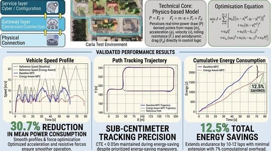
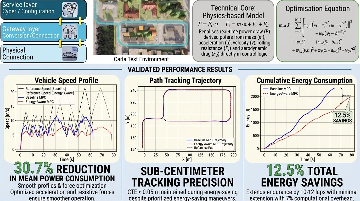
Autonomous Cyber–Physical Systems (CPS) must jointly satisfy energy efficiency, accuracy, and real-time constraints, which are typically treated separately in existing methods. This paper proposes a verifiable service-oriented CPS framework for energy-aware autonomous navigation using a high-fidelity cyber–physical twin. The approach integrates physics-based Model Predictive Control (MPC) with explicit power modeling ( P = F · v ) and Dubins curve-based trajectory generation under the 5C (connection, conversion, cyber, cognition, and configuration) architecture using CARLA for synchronized cyber–physical interaction. The proposed method achieves 30.7% reduction in mean power consumption and 12.5% reduction in total energy usage while maintaining sub-centimeter tracking error (<0.05 m). Mission duration increases by 26.3% with only 7% computational overhead, confirming real-time feasibility. The framework provides a verifiable CPS methodology that unifies physics-based control, digital twin synchronization, and service-oriented design for energy-aware autonomous navigation.

Graphical Abstract

1. Introduction

Industry 4.0, or the fourth industrial revolution, is the application of the generic concept of Cyber–Physical Systems (CPSs) to industrial production systems [1]. By definition, CPS is a new breed of complex, “software-intensive” mechatronic systems characterized by tight integration and real-time interaction between computational, communicational, and physical components and subsystems [2]. The synthesis of these complex systems is a difficult proposition that requires integrating multiple engineering disciplines with strongly coupled physical energy fields, often with limited cross-functional understanding of emergent system behavior [3]. CPS calls for a close coupling between the physical and computing domains. The focus is on getting the physics right; the rest is mathematics and computation. Currently, no general-purpose framework is available for architectural exploration and design synthesis that effectively manages the energetic interactions.

1.1. Managing Complexity Through Verification and Validation

The design of next-generation CPS is a challenging endeavor because the “complexity gap” is inherently high. Complexity is defined here as “the measure of uncertainty in achieving the Functional Requirements (FRs) of a system within their specified design range” [2]. To manage this uncertainty, a rigorous Verification and Validation (V&V) methodology is required. Following IEEE (Institute of Electrical and Electronics Engineers) 1012-2012 standards [4], V&V are technical lifecycle processes used to determine if a system is “built right” and is the “right thing”:
Verification (“did we build the thing right?”): The process of evaluating the system during development to ensure it conforms to specified input requirements and architectural consistency. Validation (“did we build the right thing?”): The process of evaluating the system at the end of development to ensure it satisfies intended use and user needs (specifically, energy-aware autonomous navigation).
For CPS, V&V is particularly difficult because the physical domain operates in continuous time, while the cyber logic operates in discrete time. This study argues that Model-Driven Development (MDD) is the most suitable approach for achieving end-to-end design automation, ensuring that model representations are formal enough to guarantee code integrity and behavioral consistency.

1.2. The Role of the Cyber–Physical Twin

A key contribution of this work is the deployment of a Cyber–Physical Twin (CPT) as the definitive implementation of the ‘Data Model’ layer within the CPS hierarchy. While often used interchangeably with “Digital Twin” (DT) in the broader literature, this framework maintains a strict functional distinction based on timing discipline and network realism.
Standard digital twins typically serve as general virtual representations for modeling physical or mechanical states; in contrast, a Cyber–Physical Twin is a specialized subclass designed for architectures requiring strict synchronization with physical clocks to ensure that virtual control decisions occur within deterministic latency windows.
Following the hierarchical definitions established by Czwick and Anderl [5], our CPT is decomposed into two distinct components:
  • The physical twin: Represented by the CARLA simulation environment, which serves as the high-fidelity ‘source of reality’.
  • The cyber twin: Serves as the intelligence layer where system behavior is optimized through energy-aware MPC strategy.
By operationalizing this dual-hierarchy paradigm, the proposed framework ensures that the bidirectional data flow (Level 2: Data Model) captured via the CARLA API fully accounts for the impacts of timing constraints and execution bounds. This specialized nomenclature ensures that our Control as a Service (CaaS) model is verified against the hybrid-system requirements of both continuous-time physics and discrete-time cyber logic.

1.3. Research Gap and Critical Analysis

Despite these advances, a critical gap persists in the architectural integration of physics-based energy optimization with kinematically-optimal path planning. While energy-aware MPC exists in various forms, its execution within a unified service-oriented framework that maintains energy awareness from the planning stage (Dubins geometry) through to real-time embedded tracking (MPC) remains underexplored. This gap manifests in several dimensions:
1.
Indirect Energy Optimization: Existing MPC implementations typically address energy efficiency indirectly through control effort penalties (e.g., u 2 ), which do not accurately reflect the nonlinear relationship between control inputs, vehicle dynamics, and actual power consumption. While control effort minimization may reduce actuator activity, it can fail to account for the velocity-dependent nature of resistive forces (rolling resistance, aerodynamic drag) and the multiplicative power relationship P = F · v .
2.
Lack of Unified Framework: Path planning and trajectory tracking are often treated as decoupled problems. Smooth path planners generate energy-efficient reference trajectories, but subsequent tracking controllers may introduce aggressive corrections that negate planning-stage optimizations. A unified approach that maintains energy awareness throughout both planning and execution phases is conspicuously absent.
3.
Insufficient Computational Feasibility Analysis: While energy-aware optimization is conceptually appealing, its practical viability on resource-constrained embedded processors (e.g., Raspberry Pi 4, NVIDIA Jetson Nano) remains underexplored. The computational overhead introduced by energy penalty terms and their impact on solver convergence and real-time performance requires rigorous quantification.
4.
Limited Tradeoff Quantification: The literature lacks systematic analysis of the fundamental tradeoff between energy efficiency and mission duration. Energy-optimal control strategies necessarily involve smoother and more gradual maneuvers that extend traversal time, a tradeoff that must be explicitly quantified and characterized for application-specific tuning.
5.
Validation Gap: Most energy-efficient control studies are validated either purely in simulation with idealized dynamics or on full-scale vehicles with ample computational resources. The intermediate domain of small-scale embedded platforms where computational, sensing, and energy constraints converge remains inadequately addressed.
6.
Architectural Fidelity Gap (CPS-DT): A significant gap exists in the systematic verification of Cyber-Physical Systems (CPS) where the digital twin is used only for visualization rather than rigorous state synchronization [6,7]. Most research fails to bridge the Level 2 (Data Model) and Level 3 (Intelligent Services) layers in a way that validates Non-Functional Requirements (NFRs) such as real-time jitter and power-to-compute ratios on embedded edge hardware. There is a distinct lack of frameworks that utilize a high-fidelity twin to provide the common vocabulary needed to synchronize discrete-time control logic with continuous-time physical dynamics [6,8].
The cyber component’s software architecture must be highly modular, integrating functions such as path planning, trajectory generation [9], and control navigation as core intelligent services (Level 3). While existing energy-aware control algorithms have been proposed [10,11,12,13], many approaches either utilize computationally heavy nonlinear solvers or fail to provide a detailed analysis of their real-time computational cost (software metrics) when targeting embedded platforms. This creates a critical gap in which methods often lack verifiable evidence that the solution meets the concurrent NFRs for low power consumption and real-time performance on a low-cost processor. Recent advancements in edge-based autonomy highlight that these services must be specifically refined to meet the target platform’s physical constraints in order to achieve true “energy-aware” operation [14].
To address gaps 1, 2, and 5, this paper presents an integrated CPS framework that employs a novel energy-aware MPC formulation incorporating instantaneous power consumption as an explicit physics-based penalty term in the optimization objective. By utilizing the computationally lightweight Sequential Least Squares Programming (SLSQP) solver, the proposed methodology ensures energy savings while adhering to the system’s hard real-time requirements. The framework is coupled with Dubins curve-based path planning [9] to generate continuous curvature-bounded trajectories inherently suited to the kinematic constraints of car-like vehicles. The complete architecture is validated within the CARLA simulator, where it is configured as a high-fidelity physical twin to emulate a small-scale Remote Controlled (RC) car platform with realistic vehicle dynamics and the computational constraints typical of embedded deployments.

1.4. Research Contributions and Novelty

The main aim of this work is to design, implement, and verify a design methodology for realizing resource-constrained and efficient autonomous CPS grounded in the foundational three-tier cyber–physical systems architecture fundamental to the Industry 4.0 paradigm [1]. This involves creating a modular hardware and software architecture, implementing the energy-aware MPC algorithm, and using the smart environment (CARLA digital twin) to provide the final user with cyber–physical functionalities and gather specific computational and power metrics. The principal conclusion is that the refined algorithmic design successfully meets the energy consumption NFR, achieving a 12.5% reduction in total energy usage. Crucially, the computational metrics confirm the software’s real-time feasibility, validating the system’s architecture for future deployment on edge hardware. Thus, the study provides a proven software design methodology for optimizing platform endurance within the strict constraints of real-time CPS.
The primary contributions of this work are:
1.
Physics-Based Energy-Aware MPC Formulation: An MPC cost function that explicitly incorporates instantaneous power consumption ( P = F · v ) derived from first-principles vehicle dynamics, including rolling resistance, aerodynamic drag, and inertial forces. Unlike conventional control effort penalties, this formulation directly optimizes the physical quantity of interest—power consumption—enabling more effective energy management.
2.
Unified Energy-Efficient Navigation Framework: Synergistic integration of energy-efficient trajectory generation (Dubins curves) with energy-aware trajectory tracking control (MPC), creating a cohesive navigation system where energy optimization is maintained throughout both planning and execution phases. This addresses the decoupling problem prevalent in existing approaches.
3.
Comprehensive Simulation Validation with Trade-Off Analysis: Systematic evaluation in CARLA demonstrating quantifiable improvements (30.7% mean power reduction, 12.5% total energy savings) alongside rigorous analysis of the energy–time tradeoff (26.3% mission duration increase) and computational overhead (7% solver time increase). This provides actionable insights for practitioners balancing competing objectives in real-world deployments.
4.
Embedded Platform-Oriented Insights: Analysis of control smoothness, solver computational requirements, battery lifetime projections, and real-time feasibility specifically tailored to resource-constrained embedded platforms (Raspberry Pi 4, Jetson Nano). This bridges the validation gap between idealized simulation and practical embedded deployment.
5.
Reproducible Methodology: Detailed exposition of the complete system pipeline, vehicle modeling, MPC formulation, Dubins path generation, and simulation configuration to enable replication and extension by the research community. A detailed exposition of the complete system pipeline—vehicle modeling, MPC formulation, and Dubins path generation—is provided as an open-source implementation at https://github.com/OA-1234/Omar-DT (accessed on 2 April 2026). This includes calibration procedures and raw datasets to facilitate immediate technology transfer to hardware platforms and foster collaboration within the research community. Open-source implementation considerations and calibration procedures facilitate technology transfer to hardware platforms.
6.
Formalized CPS Verification Methodology: Development of a systematic verification pipeline using a high-fidelity cyber–physical twin [7]. Unlike standard simulations, this methodology utilizes the CARLA Python (3.7) API to establish a “common vocabulary” between the discrete-time cyber control logic and the continuous-time physical environment. This allows for the simultaneous verification of both functional requirements (tracking accuracy) and Non-Functional Requirements (NFRs) such as solver latency and power efficiency, providing a template for verifying software-defined vehicles [6].

1.5. Summary of Research Impact

Table 1 provides a concise mapping of the research contributions to the functional layers of the proposed CPS framework, bridging the identified complexity gaps.

1.6. Novel Aspects Compared to State-of-the-Art

Compared to the existing literature, our approach offers several distinctive advantages:
  • Versus Control Effort Minimization [15]: While traditional MPC uses quadratic control penalties ( w u u 2 ), our energy term ( w E P 2 ) directly penalizes power consumption, capturing the nonlinear and velocity-dependent nature of energy expenditure. This results in qualitatively different control behavior: energy-aware MPC favors gradual velocity reduction over hard braking (reducing regenerative losses) and avoids high-speed acceleration (minimizing aerodynamic drag losses).
  • Versus Adaptive MPC [13]: Liu et al.’s adaptive approach adjusts MPC weights based on mission state, but lacks explicit power modeling. Our framework provides a principled physics-based energy penalty that does not require ad hoc weight adaptation strategies, thereby simplifying implementation while achieving comparable or superior energy savings.
  • Versus Path Planning-Only Approaches [10,11]: Unlike tracking controllers that ignore path geometry or methods that generate smooth trajectories but lack closed-loop tracking, our work provides a unified SOICPS framework. The proposed architecture encapsulates path planning and energy-aware control as modular intelligent services (Level 3). This ensures that the global geometric optimality of Dubins curves is preserved even while the MPC performs local physics-based power minimization, preventing the aggressive corrective maneuvers common in decoupled systems.
  • Versus Empirical Energy Optimization [12]: Yeom’s work has demonstrated the energy benefits of smooth control through empirical tuning. Here, we provide a systematic optimization-based framework with explicit energy modeling, enabling scalability to different vehicle platforms and mission profiles without manual retuning.
  • Versus Conventional Simulation Validation [16,17]: While many studies use simulations purely for visual validation of path-following, our approach treats the smart simulation environment as a digital twin that operationalizes the cyber/data layer of standard CPS architectures [1]. By synchronizing state-data at a fixed 10 Hz frequency and measuring software-specific metrics (solver time) alongside physical metrics (energy), we bridge the gap between abstract control theory and embedded software integrity. This aligns our work with the Industry 4.0/5.0 paradigms, ensuring that green computing objectives are met through verifiable software design rather than just theoretical modeling [18].
In short, the primary novelty of this work lies not in the standalone CaaS MPC formulation but in the synergistic integration of a service-oriented 5C architecture with high-fidelity physical modeling and Dubins-based path planning. This creates a verifiable “cyber–physical twin” workflow that bridges the gap between conceptual software design and embedded-ready autonomous control.
The rest of this paper is organized as follows: Section 2 reviews the relevant literature on energy-efficient path planning and MPC with critical assessment; Section 3 details the system architecture, vehicle modeling, MPC formulation, and simulation setup; Section 4 presents experimental results and performance metrics; Section 5 provides in-depth analysis, interpretation, and critical evaluation; and Section 6 concludes with future research directions.

2. Related Work

2.1. Energy-Efficient Path Planning

Energy efficiency has emerged as a paramount consideration in autonomous systems research, driven by the dual imperatives of extending operational endurance and reducing environmental impact [10]. For battery-powered mobile robots, energy consumption directly determines mission duration, operational range, and system sustainability. Furthermore, aggressive control actions not only deplete batteries rapidly but also induce mechanical wear on actuators and drivetrains, compromising long-term reliability. Critically, the interdependence between control strategy, trajectory smoothness, and energy consumption necessitates holistic optimization frameworks that transcend traditional control paradigms focused solely on tracking accuracy.
Recent advances in trajectory optimization have demonstrated strong correlations between path smoothness, curvature minimization, and energy efficiency. Valera et al. [11] developed trajectory planning algorithms for lightweight autonomous vehicles that minimize path curvature while maintaining motion continuity, achieving inherently smoother and more energy-efficient trajectories. Similarly, Zhang et al. [10] presented an energy-efficient framework for Ackermann-steering vehicles that optimizes steering angles to reduce overall power consumption. Yeom [12] further emphasized the significance of control smoothness, demonstrating that optimized control laws can substantially reduce energy expenditure in car-like mobile robots. However, these approaches primarily focus on open-loop trajectory optimization, lacking the receding horizon adaptability and constraint handling capabilities essential for real-time autonomous navigation in dynamic environments.
Driven by the imperative to extend operational range and reduce environmental impact in autonomous mobile systems, energy-efficient trajectory planning has become a focal research area. Wu et al. [19] provide a comprehensive review of energy efficiency techniques in autonomous mobile robots, identifying optimized path planning and adaptive control as key enablers of sustainable autonomy. Their analysis emphasizes that energy consumption in mobile robots is dominated by propulsion forces overcoming rolling resistance, aerodynamic drag, and inertial acceleration, which makes trajectory smoothness a critical factor.
Valera et al. [11] developed an optimal trajectory planning algorithm for lightweight autonomous vehicles that minimizes both total path length and maximum curvature. By formulating the planning problem as a constrained optimization over waypoint sequences, their approach generates smooth and energy-efficient trajectories that reduce unnecessary steering corrections and acceleration spikes. Experimental validation demonstrated reduced energy consumption and improved mechanical longevity compared to conventional shortest-path planners.
Zhang et al. [10] presented an energy-efficient path planning framework specifically tailored for Ackermann-steering vehicles. Their method incorporates vehicle kinematic constraints and optimizes steering angles to minimize cumulative energy expenditure along candidate paths. By explicitly modeling rolling resistance and aerodynamic drag forces, the planner selects trajectories that balance path length with energy cost. Simulation results showed energy savings of 15–20% compared to traditional geometric path planners such as Rapidly-exploring Random Trees (RRT).
Yeom [12] investigated the relationship between control law design and energy efficiency for car-like mobile robots. Through theoretical analysis and simulation experiments, Yeom demonstrated that smooth and gradual control inputs significantly reduce instantaneous power demand and cumulative energy consumption. Their study underscored the importance of incorporating control smoothness constraints or penalty terms into optimization frameworks to achieve energy-efficient motion.
Cuervo-Méndez et al. [20] empirically analyzed trajectory execution using a small-scale JetRacer platform. Their work demonstrated a direct correlation between steering angle limitations and cross-track error during autonomous cornering. These findings highlight the physical constraints of small-scale platforms, underscoring the need to explicitly handle dynamic limits within the control architecture to maintain tracking accuracy without over-saturating actuators.
Critical Assessment: While these path planning approaches achieve notable energy savings, they suffer from several limitations: (1) open-loop nature —paths are generated offline without feedback, making them vulnerable to disturbances and model uncertainties; (2) decoupling from tracking control —even smooth planned trajectories can be negated by aggressive tracking controllers; (3) limited constraint handling —most methods lack systematic integration of actuator limits, obstacle avoidance, and safety constraints. Our work addresses these limitations through closed-loop MPC with explicit energy optimization and comprehensive constraint handling.

2.2. Model Predictive Control for Autonomous Vehicles

Among advanced control methodologies, Model Predictive Control (MPC) has garnered significant attention for trajectory tracking in autonomous vehicles thanks to its ability to systematically handle constraints, optimize over prediction horizons, and explicitly incorporate multiple objectives into a unified cost function [15]. Lin and Lin [15] applied MPC to enhance navigation safety and accuracy by optimizing control inputs under dynamic constraints, achieving smooth and stable vehicle motion. Liu et al. [13] introduced an adaptive energy-aware MPC approach for autonomous surface vehicles that dynamically adjusts control parameters to minimize energy usage while preserving trajectory fidelity, demonstrating MPC’s versatility in balancing competing objectives.
Traditional autonomous control relies heavily on optimization-based methods, with MPC being highly favored due to its ability to handle constraints and its inherent predictive capabilities [15]. However, the computational expense of solving the underlying optimization problem remains a significant challenge for real-time deployment, necessitating careful software tool selection based on efficiency and platform suitability. Furthermore, the development of robust autonomous software requires sophisticated Verification and Validation (V&V) methodologies. To address this, the digital twin concept has emerged as a crucial software engineering practice for CPS, acting as the high-fidelity ‘data model layer (Level 2) in the architectural hierarchy. The selection of simulation-based testing environments is critical for the verification of autonomous vehicle software, particularly when evaluating performance in complex driving scenarios that are expensive or dangerous to replicate in the physical world [21].
MPC’s emergence as a powerful framework for trajectory tracking and motion control in autonomous vehicles is due to its systematic handling of constraints, multi-objective optimization capabilities, and receding horizon strategy [22]. MPC formulates control as a finite-horizon optimal control problem that is solved iteratively at each time step, applying only the first control input and re-solving at the next step based on updated state measurements.
Lin and Lin [15] applied MPC to enhance navigation safety and accuracy in autonomous vehicles. Their formulation incorporates tracking error minimization, steering effort penalties, and velocity regulation into a unified quadratic cost function. By optimizing control inputs subject to actuation limits and kinematic constraints, their MPC controller achieved smooth and stable motion with reduced overshoot and oscillations. Simulation results demonstrated improved path following accuracy and passenger comfort compared to Proportional–Integral–Derivative (PID) controllers.
Liu et al. [13] introduced an adaptive energy-aware MPC approach for Autonomous Surface Vehicles (ASVs). Their method dynamically adjusts cost function weights based on real-time energy state and mission objectives, prioritizing energy conservation during low-criticality maneuvers and accuracy during high-priority tasks. Experimental validation showed that adaptive energy-aware MPC extended mission duration by 18% while maintaining trajectory fidelity within acceptable bounds. This work highlights MPC’s flexibility in balancing multiple potentially competing objectives.
Carvalho et al. [23] explored Nonlinear MPC (NMPC) for autonomous vehicle lane keeping, demonstrating the ability to handle nonlinear vehicle dynamics and tire slip effects. Their NMPC formulation incorporated lateral position error, heading error, and control effort into the cost function that was solved using Sequential Quadratic Programming (SQP). Real-world experiments confirmed robust performance under varying road conditions and vehicle speeds.
Beyond single-agent optimal control, the broader operational context of industrial cyber–physical systems often necessitates cooperative coordination among multiple autonomous entities under strict communication and physical constraints. Recent state-of-the-art advancements in multi-agent systems provide complementary theoretical grounding for extending standalone CPS architectures. For instance, Wang et al. [24] developed an adaptive nonlinear containment control strategy utilizing event-triggered inputs to guarantee multi-agent coordination while strictly enforcing full-state constraints and reducing communication burdens. Similarly, for environments subject to dynamic uncertainties, optimized adaptive finite-time consensus control has been demonstrated to maintain system-wide stability even in the presence of stochastic nonlinear faults [25]. While the present study focuses on the localized energy-aware MPC of an individual autonomous vehicle, these nonlinear consensus and event-triggered containment strategies represent a crucial theoretical trajectory for extending our verifiable framework to cooperative network-constrained multi-agent environments. While our work focuses on single-vehicle energy optimization, the broader landscape of nonlinear control has seen significant advancements in managing high-order constraints and stochastic uncertainties. Recent studies in state-constrained containment control and optimized adaptive finite-time consensus for nonlinear multi-agent systems offer critical insights into handling non-affine faults and event-triggered inputs. These methodologies provide a theoretical bridge between the deterministic control loops used in this study and the complex, stochastic interactions inherent in large-scale cooperative autonomous fleets. Critical Assessment: Despite these advances, most existing MPC implementations for ground vehicles prioritize tracking accuracy and safety, with energy efficiency addressed implicitly through control effort penalties rather than explicit power minimization. Fundamental limitations include: (1) indirect energy optimization—control effort penalties ( u 2 ) do not reflect actual power consumption physics; (2) lack of physics-based energy modeling —velocity-dependent resistive forces and power relationships ( P = F · v ) are not explicitly captured; (3) insufficient computational analysis—impact of additional energy terms on solver performance and real-time feasibility remains underexplored. Our work directly addresses these gaps through physics-based energy modeling within the MPC framework.

2.3. Simulation Platforms for Autonomous Navigation

Simulation platforms such as CARLA (Car Learning to Act) [26] have become indispensable tools for validating autonomous navigation systems prior to real-world deployment. CARLA provides a photorealistic physics-based urban driving environment that enables systematic algorithm development and reproducible performance evaluation [16,17]. Shet et al. [16] utilized CARLA to develop and test autonomous path planning frameworks under diverse urban conditions, while Fatima et al. [17] integrated CARLA with ROS2 for real-time simulation of sensor data, control loops, and decision-making processes.
In this context, the CARLA simulation environment is utilized as the Digital Twin (DT) of the smart environment of the physical layer, providing a high-fidelity deterministic platform for testing the entire control stack [16,17]. By operating as a knowledge-driven data model, this environment establishes a common vocabulary for heterogeneous components, effectively bridging the architectural gap between high-level intelligent services and physical hardware [6,7]. This framework facilitates a comprehensive evaluation of the system across multiple architectural viewpoints—Functional (F), Behavioral (B), and Structural (S)—ensuring that the complex emergent properties of the CPS are analyzed as an integrated whole rather than in isolation [27]. Such an approach enables rigorous measurement of software metrics under deterministic conditions and verification of Non-Functional Requirements (NFRs) within a robust model-driven engineering framework [28], which is increasingly critical as systems transition toward the Industry 5.0 paradigm of sustainable resource-efficient operations. By using the CARLA Python API as the primary communication interface, the architecture operationalizes the data model layer (Level 2) of the CPS hierarchy, maintaining the state consistency required to validate real-time predictive models [7]. This transition enables proactive AI-driven optimization that aligns with modern industrial digitalization roadmaps for green computing and energy efficiency [18], providing the empirical evidence necessary to validate that autonomous services meet modern industrial standards.
Simulation environments provide essential tools for developing, testing, and validating autonomous navigation algorithms under controlled and reproducible conditions prior to real-world deployment [26]. CARLA has become one of the most widely adopted open-source simulators for autonomous driving research, offering photorealistic rendering, physics-based vehicle dynamics, and programmable sensor suites including cameras, LiDAR, radar, and GPS [26].
Shet et al. [16] used CARLA to develop and evaluate autonomous path-planning frameworks for urban driving scenarios. Their work demonstrated CARLA’s capabilities in simulating complex traffic interactions, dynamic obstacles, and varying environmental conditions. By systematically testing planning algorithms across diverse scenarios, they established performance baselines and identified failure modes prior to real-world testing.
Fatima et al. [17] integrated CARLA with Robot Operating System 2 (ROS2) to create a comprehensive autonomous vehicle simulation platform. Their architecture enables real-time streaming of data from CARLA sensors to ROS2 nodes to facilitate seamless integration of perception, planning, and control modules. This integration streamlines algorithm development workflows and enables hardware-in-the-loop testing where embedded controllers (e.g., Raspberry Pi) interface with simulated vehicle dynamics.
Palanisamy [29] developed multi-agent scenarios in CARLA for testing cooperative and competitive autonomous behaviors. This work demonstrated CARLA’s scalability and flexibility in creating customized simulation environments, including urban intersections, highway merging, and parking scenarios. The ability to spawn multiple vehicles with independent control policies enables systematic evaluation of collision avoidance, coordination, and decision-making algorithms.
CARLA’s synchronous simulation mode ensures deterministic execution where each simulation step progresses only after all client commands are processed [26]. This feature is critical for reproducible experiments and fair comparisons between algorithms. Additionally, CARLA’s modular architecture allows users to configure vehicle parameters (mass, dimensions, wheel geometry) to accurately represent target platforms, including small-scale RC cars as used in this study.
Critical Assessment: While CARLA provides high-fidelity simulation, several caveats warrant consideration: (1) sim-to-real gap—idealized physics models may not capture hardware imperfections (sensor noise, actuator delays, tire slip variability); (2) computational requirements—photorealistic rendering demands significant Graphical Processor unit (GPU) resources, potentially limiting real-time performance on embedded systems; (3) limited embedded platform modeling—CARLA lacks built-in models of computational constraints, memory limitations, and energy consumption of target embedded processors. Our methodology addresses these concerns through careful parameter calibration and computational profiling relevant to embedded deployment.

2.4. Dubins Path Planning

Dubins curves [30] represent a fundamental result in path planning for vehicles with bounded turning radius, proving that the shortest path between two configurations (position and heading) for a typical Dubins vehicle consists of at most three segments: two circular arcs of maximum curvature, and one straight line connecting the arcs tangentially. For car-like robots with non-holonomic constraints (i.e., the instantaneous velocity is perpendicular to the heading), Dubins paths provide an optimal solution that balances path length and curvature.
There are two major classes of Dubins paths for two given configurations: one is CSC, and the other is CCC, where C represents a circular arc and S represents a straight line. They are consecutively connected and are tangent to each other. Two possible turns, right and left, further expand the CSC type into LSL, LSR, RSR, and RSL paths and the CCC class into RLR and LRL. Thus, there are six possible types of Dubins paths for a given set of configurations. A complete set of Dubins paths includes these six types and their sub-paths, such as CS, SC, CC [30]. LaValle [31] provides a comprehensive treatment of Dubins paths in the context of motion planning, including efficient algorithms for path generation and waypoint sampling.
Dubins paths naturally yield smooth and energy-efficient trajectories by minimizing path length while satisfying curvature constraints. Sharp turns are avoided in favor of gentle arcs, reducing centripetal forces and steering effort. This intrinsic smoothness aligns well with energy optimization objectives, making Dubins curves an ideal choice for energy-aware path planning [9].
This work uses the pydubins library [9], an open-source Python implementation of Dubins path planning algorithms. The library efficiently computes shortest curvature-constrained paths, providing sampled waypoints for trajectory tracking controllers.
Critical Assessment: While Dubins paths provide an elegantly optimal geometric foundation, their primary value in this architecture is as a high-fidelity reference for the MPC tracking layer. By utilizing Dubins paths, the system gains several strategic advantages:
  • Decoupled Complexity: The Dubins planner provides a kinematically feasible geometric skeleton, allowing the MPC to focus exclusively on solving high-order dynamic constraints such as acceleration limits and tire forces.
  • Reference Stability: The fixed-curvature nature of the Dubins arcs provides a predictable and smooth global reference. This prevents the MPC from oscillating and allows it to prioritize energy-efficient velocity profiles over the predefined geometric path.
  • Hierarchical Robustness: While the base Dubins model is obstacle-blind, its role as a flexible reference allows the MPC to handle local environmental deviations. This hierarchy ensures that global reachability and local dynamic feasibility are satisfied simultaneously.
Consequently, the combination of Dubins’ geometry and MPC optimization creates a robust cyber–physical loop: the geometric model ensures global path optimality, while the controller enforces real-world physical and energy-aware constraints.

2.5. Summary of Literature Gaps

Table 2, Table 3 and Table 4 provide a structured decomposition of the state of the art across three critical domains: path planning, predictive control, and simulation-based validation. This categorization highlights the divergence between theoretical control design and the requirements for high-fidelity cyber–physical systems.
Category 1
(Trajectory and Path Planning). This category focuses on the geometric layer, how the vehicle establishes a feasible path based on kinematic constraints.
Category 2
(Predictive Control and Optimization). This category examines the cyber layer, the algorithms used to manage constraints and optimize platform performance.
Category 3
(Digital Twin and Validation Frameworks). This category evaluates the physical–cyber bridge, how software integrity is verified against realistic physics.
Table 2. Summary of the literature on energy-efficient path planning.
ReferenceKey MethodEnergy FocusPrimary Limitation
[30]Geometric arcsDistanceNo dynamic or inertial constraints.
[11]Curvature opt.SmoothingOpen-loop; lacks real-time feedback.
[10]Ackermann RRTResistanceHigh computational cost for RRT solvers.
[9]Dubins curvesKinematicsStatic velocity; decoupled from control.
Table 3. Summary of the literature on Model Predictive Control (MPC).
ReferenceControl TypeCost FunctionPrimary Limitation
[15]Standard MPC u 2 (Effort)Indirect link to physical power consumption.
[13]Adaptive MPCWeight-shiftingLacks physics-based P = F · v model.
[12]Smooth MPCJ-integralNo hard real-time or embedded analysis.
[23]Nonlinear MPCError/EffortHigh latency; not optimized for CaaS
(Control as a Service).
Table 4. Summary of validation platforms and frameworks.
ReferencePlatformModel LevelGap in Validation
[26]CARLAGeneral simLacks embedded CPU/power profiling.
[17]ROS2/CARLAMiddlewareHigh jitter; no focus on NFR verification.
[16]Urban SimVisualizationNo state-consistency or deterministic metrics.
[32]F1TENTHSmall-scaleFocuses on speed/racing over energy.
As summarized in Table 2, Table 3 and Table 4, the literature survey across trajectory planning, predictive control, and validation platforms reveals a significant divergence between theoretical control design and the practical requirements for high-fidelity industrial cyber–physical systems. Rather than treating these domains in isolation, this study identifies a critical need for their convergence to address the six core research gaps established in Section 1.3, particularly the absence of physics-based energy optimization in MPC and the lack of verifiable state synchronization in digital twin frameworks. By leveraging the design traceability matrix in Table 5, the proposed framework maps these limitations from the literature directly to specific Functional Requirements (FRs), providing a formal basis for the Service-Oriented Industrial Cyber–Physical System Architecture (SOICPS) architecture and the subsequent validation of energy-efficiency Non-Functional Requirements (NFRs).

3. Proposed Service-Oriented Industrial Cyber–Physical System Architecture (SOICPS) Design Framework

The design of Cyber–Physical Systems (CPS) is inherently challenging, as there is no “one-size-fits-all” methodology that addresses the high degree of coupling between discrete computational logic and continuous physical dynamics. This research adopts a formal axiomatic design framework to bridge the so-called complexity gap, defined as the measure of uncertainty in achieving Functional Requirements (FRs). To ensure a Verifiable and Validated (V&V) system, we synthesize the three-tier CPS model [1] by starting with the procedural functional 5C architecture proposed by Lee et al. [3].

3.1. Synthesis Challenge vs. Design Solution: Composition and Adaptive Design in Cyber–Physical Systems Using the Function–Behavior–Structure (FBS) Design Methodology

CPS design poses significant challenges in system composition and development due to the heterogeneity, dynamic interactions, and multi-domain requirements between cyber and physical. A key challenge is ensuring both compositionality, where system-level behavior can be derived from individual components, and composability, which allows for flexible integration and runtime reconfiguration. Existing approaches struggle to simultaneously address functional, non-functional (e.g., safety, security, QoS), and physical properties while also ensuring interoperability and coordinated interaction across distributed components.
Furthermore, the largely structure-centric traditional design methodologies fail to adequately capture the adaptive and evolving nature of Industry 4.0 systems. To overcome these challenges, emerging solutions promote semantically rich composition models combined with adaptive design frameworks. In particular, integrating ontology-driven approaches with the Function–Behavior–Structure (FBS) methodology enables a unified representation of system functionality, behavior, and structure in support of both design-time verification and runtime adaptability. These approaches facilitate the development of evolvable and self-adaptive CPS by embedding functional and behavioral reasoning into system control, thereby ensuring robust composition, interoperability, and responsiveness in dynamic environments [33,34].
In this manuscript, a distinction is made between a standard Digital Twin (DT) and a Cyber–Physical Twin (CPT). While DTs typically serve as passive virtual representations for monitoring, CPTs facilitate active bidirectional synchronization between the cyber domain (MPC logic) and the physical domain (CARLA physics engine), serving as a high-fidelity verification ground for embedded intelligence.

3.2. Conceptual Foundation: The Industry 4.0 Triad and Digital Twins

Autonomous navigation in modern intelligent vehicles represents a pinnacle of Cyber–Physical Systems (CPS), where computational control logic and physical vehicle dynamics are deeply integrated [1,2]. In this paradigm, system behavior is defined by the synergy between the continuous-time physical domain and the discrete-time cyber domain [1]. Following the foundational architecture of Industry 4.0, a robust CPS is organized into three distinct tiers: (i) physical objects, (ii) data models within a networked infrastructure, and (iii) intelligent services derived from available data [3,5].
Modern autonomous micro-mobility systems are complex realizations of this hierarchy, in which functional correctness and Non-Functional Requirements (NFRs) are determined primarily by the embedded software stack [3]. As the industry transitions toward software-defined architectures, managing complexity on resource-constrained platforms becomes a primary challenge [6]. To address this, the proposed framework utilizes the Digital Twin (DT) as the definitive implementation of the data model layer, acting as a high-fidelity virtual mirror that maintains state-synchronization to validate intelligent services against real-world physical constraints [7].

3.3. Structural Hierarchy: Three-Tier and 5C Integration

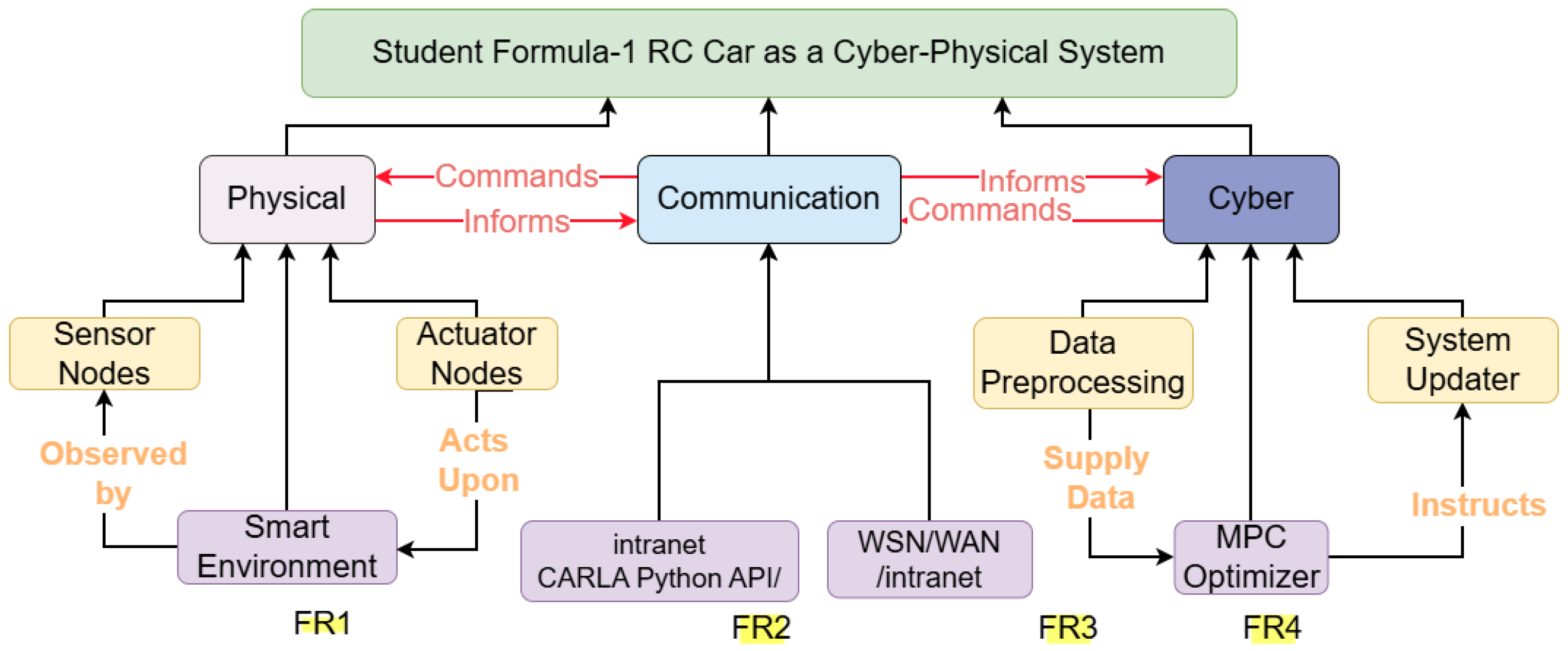
To bridge the gap between theoretical control and practical implementation, the SOICPS methodology is structured around a modular architecture aligned with Industry 4.0 principles [8]. As illustrated in Figure 1, the framework organizes the system into three interdependent functional domains:
  • Level 1 (Physical Layer): Comprises the vehicle dynamics and environment, modeled within the CARLA digital twin to represent a small-scale Ackermann-steered platform.
  • Level 2 (Data Model/Gateway): Functions as the communication bridge and state-synchronization layer, ensuring deterministic data flow via the CARLA Python API.
  • Level 3 (Intelligent Services): Focuses on the deployment of Control as a Service (CaaS) [35], featuring the synergistic integration of Dubins path planning and the proposed energy-aware MPC.
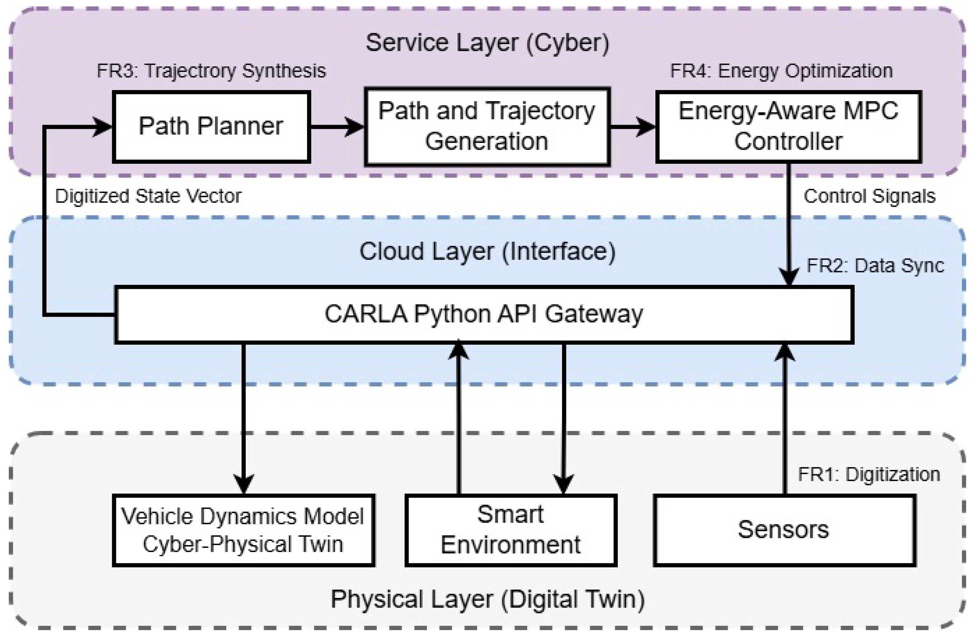
Figure 1. Proposed three-tier service-oriented CPS (SOICPS) architecture for energy-aware autonomous navigation. The framework is organized into the service layer (computation), gateway layer (synchronization), and physical layer (digitized environment), mapping directly to functional requirements FR1–FR4.
Software 05 00031 g001
While the three-level model provides structural organization, the implementation follows the 5C architecture to ensure traceability from data acquisition to autonomous configuration [12]. Table 6 illustrates how these architectural layers map to the 5C levels—connection, conversion, cyber, cognition, and configuration—to provide a common vocabulary for formal Verification and Validation (V&V). It demonstrates how each research contribution is systematically derived from the identified gaps and subsequently verified through quantitative or architectural validation.

3.4. Service-Oriented Paradigm and Functional Requirements

The primary contribution of this paper lies in the SOICPS paradigm, which encapsulates the vehicle’s intelligence into modular, interoperable services (FR1–FR4). By integrating the Dubins path planner (FR3) and the energy-aware MPC (FR4) as coordinated services within the 5C architecture, the framework ensures that non-functional energy requirements are not an ‘add-on’ feature but an inherent property of the synchronized cyber–physical loop [14].
To ensure the integrity of the digital twin and the deterministic execution of the control loop, the SOICPS is designed to satisfy four primary Functional Requirements (FRs):
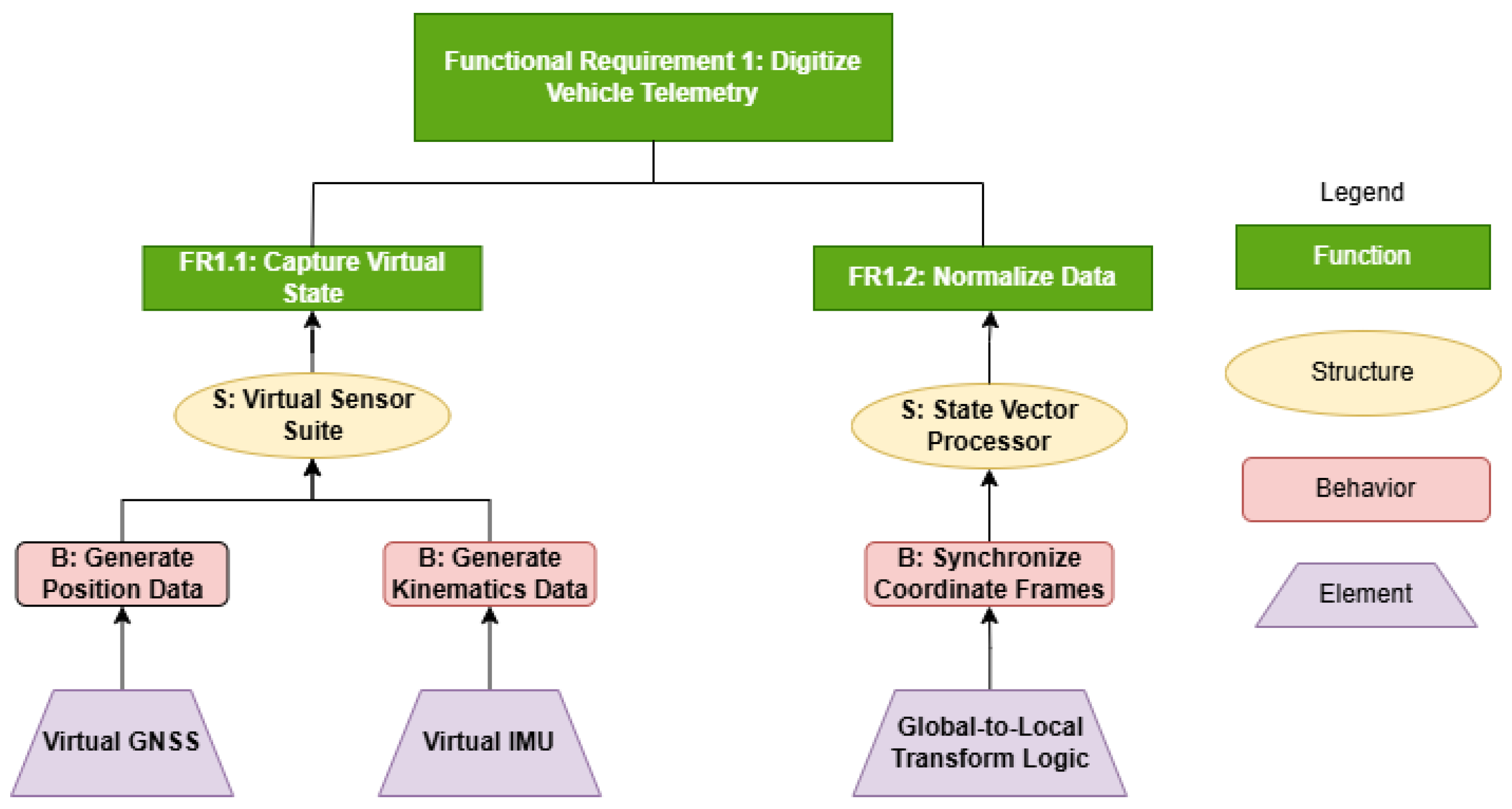
  • FR1: Digitization of Driving Data: The real-time extraction of vehicle telemetry (position, velocity, heading) from the physical simulation, fulfilling the requirement for the physical domain to be “observed” by the cyber domain.
  • FR2: Data Synchronization: The management of deterministic data flow between the client-side logic and the server-side simulation, ensuring the 10 Hz synchronization required for stable control.
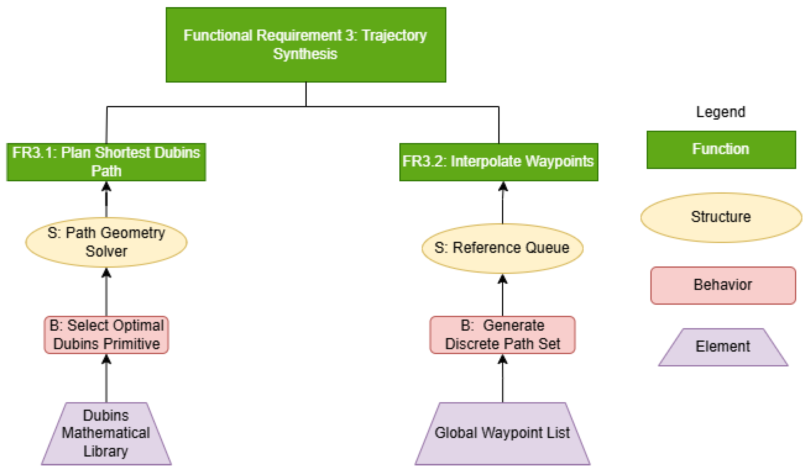
  • FR3: Trajectory Synthesis: The generation of kinematically feasible Dubins reference paths. This is implemented through a data preprocessing module that prepares raw sensor streams for the optimizer.
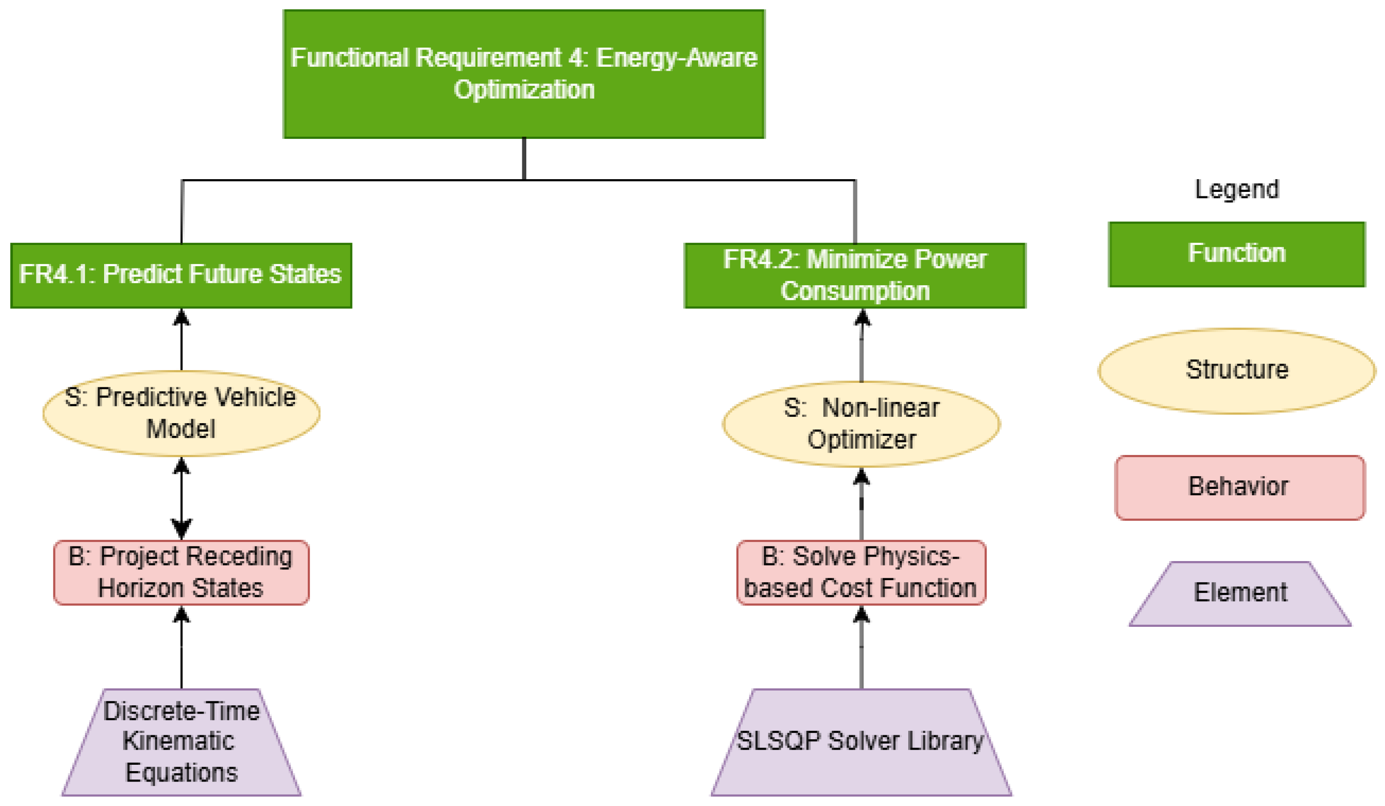
  • FR4: Energy-Aware Optimization: The computation of optimal control inputs using an MPC optimizer to balance tracking accuracy with physics-based power constraints.

3.5. Module Implementation and Closed-Loop Feedback

As shown in the deterministic feedback loop of Figure 1, the architecture establishes a closed-loop “inform and command” pathway between the cyber and physical domains.The system intelligence is partitioned into modular components to ensure that the control logic remains decoupled from the simulation platform.
At each 10 Hz control cycle, the MPC optimizer receives the current vehicle state, queries the nearest reference waypoint from the Dubins path, and solves the optimization problem [15]. The optimizer then “instructs” a system updater module, which finalizes the cycle by updating the virtual state before “exporting” the next command set to the physical layer via the gateway.This hierarchical decomposition ensures that every software component is directly mapped to a functional requirement, providing the formal verification evidence that the system is “built right” according to its architectural specifications.

3.6. Mapping Functional Requirements and Architecture

To ensure the integrity of the digital twin, the system is designed to satisfy four primary Functional Requirements (FRs).
As illustrated in Figure 1, the architecture establishes a deterministic feedback loop between the cyber and physical domains. The physical layer (CARLA) provides the raw environmental data, which undergoes digitization (FR1) to be consumed by the system. The gateway layer, implemented via the CARLA Python API, manages the data synchronization (FR2) between the simulator’s continuous-time physics and the controller’s discrete-time logic.
The framework comprises three primary modules that execute these requirements:
  • Path Planning Module (Cyber/Service Layer): Satisfies FR3 by generating smooth curvature-bounded reference trajectories using Dubins curves.
  • MPC Controller (Cyber/Service Layer): Satisfies FR4 by computing optimal steering and acceleration commands to track the reference trajectory while minimizing a multi-objective cost function.
  • Simulation Environment (Physical/Digital Twin): Satisfies FR1 by providing high-fidelity vehicle dynamics and sensor data. The CARLA Python API acts as the gateway (FR2), serving as a knowledge-driven model that defines the common vocabulary for interactions between the controller and the environment [6].
To formalize the interaction between the cyber and physical domains, the framework adopts a structured meta-model [36,37]. This approach decouples the abstract architectural viewpoints from the mathematical models governing the system’s intelligence.
As illustrated in Figure 2, the system architecture is designed as a modular CPS following the interaction patterns defined in the meta-model framework. The architecture is partitioned into three primary domains, namely, physical, communication, and cyber.
  • Physical Domain (FR1): This domain contains the smart environment (CARLA Town03) and the sensor/actuator suite. The physical entity is observed by sensors which feed data into the system, while the actuators receive direct commands to influence the environment. This fulfills the digitization requirement (FR1).
  • Communication Domain (FR2): Serving as the interoperability layer, the CARLA Python API acts as the gateway between the simulated physics and the control logic. This domain manages the bidirectional flow of information (‘Exports’ to cyber and ‘Commands’ to physical) while ensuring the 10Hz deterministic synchronization required for stable control (FR2).
  • Cyber Domain (FR3 & FR4): This is the intelligence layer of the system. It consists of:
    -
    Data Preprocessing: Prepares the raw sensor streams for the optimizer, satisfying the trajectory synthesis logic (FR3).
    -
    MPC Optimizer: The core functional component that instructs the system updater based on energy-aware cost functions (FR4).
    -
    System Updater: Finalizes the control loop by updating the virtual state before exporting the next command set to the communication layer.
The ‘Informs’ and ‘Commands’ pathways shown in Figure 2 highlight the closed-loop and coupled nature of the CPS design. By separating the MPC optimizer from the CARLA Python API, the architecture ensures that the control intelligence remains decoupled from the simulation platform, allowing for high modularity and easier model recalibration.
Integration of the Dubins curve and MPC follows a hierarchical coupling mechanism. The Dubins curve acts as an offline path planner to generate a kinematically feasible shortest-distance reference trajectory z r e f = [ x r e f , y r e f , ψ r e f ] T . This reference is then consumed by the MPC, which acts as an online tracking controller that optimizes control inputs to minimize state error while penalizing instantaneous power consumption.
At each control cycle (10 Hz), the MPC controller receives the current vehicle state from CARLA, queries the nearest reference waypoint from the Dubins path, formulates and solves the optimization problem, and commands the computed controls back to the simulated vehicle. This closed-loop interaction represents the fundamental CPS feedback mechanism in which the cyber domain must satisfy the strict temporal and physical constraints of the physical domain.

3.7. Functional Decomposition and Architectural Verification

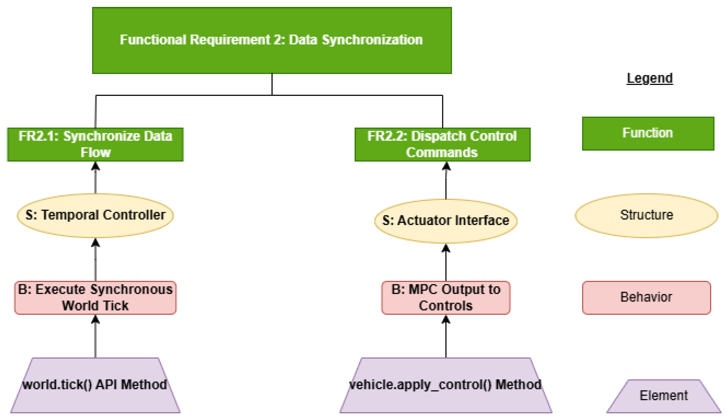
To verify the functionality and internal logic of the 5C levels, the system is decomposed into four Functional Requirements (FRs). Each FR is analyzed from Functional, Behavioral, and Structural (FBS) viewpoints to ensure that the digital twin maintains strict state consistency with the physical environment [6,27]. This granular mapping is what allows the framework to transition from abstract “intelligent services” to concrete software implementation.
The hierarchical decomposition presented in Figure 3, Figure 4, Figure 5 and Figure 6 illustrates the strict traceability between the system’s objectives and its implementation. By nesting each element within a specific behavior and structure, the methodology ensures that every software component (e.g., the SLSQP solver) is directly mapped to a functional requirement. This structure provides the ‘common vocabulary’ necessary to synchronize the discrete cyber logic with the continuous physical simulation, thereby fulfilling the requirements for a data model (Level 2) digital twin [6,7]. Furthermore, this FBS mapping serves as the formal verification evidence proving the system is ‘built right’ according to its architectural specifications.

3.8. Requirements Traceability

To ensure the system is ‘built right’ (verification) and is the ‘right thing’ (validation) per IEEE 1012-2012, Table 6 maps the research gaps identified in Section 2.5 to the implemented FRs and their validated outcomes.

Design Traceability Matrix: Mapping Gaps to System Requirements

To address the complexity of modern CPS, this research utilizes a traceability approach that maps the identified literature gaps to specific Functional Requirements (FRs) and intended contributions, ensuring a formal Verification and Validation (V&V) process.
The mapping illustrated in Table 6 establishes a formal link between the limitations of the current literature and the system’s design parameters. Specifically, addressing Gap 1 through the implementation of FR3 allows for the transformation of abstract control effort into a quantifiable physical constraint. This ensures that the system’s energy efficiency is not merely a side effect of “smooth” control but a verified outcome of the physics-based modeling integrated into the cyber–physical twin architecture.

3.9. The Cyber–Physical Twin: Vehicle Modeling

To bridge the gap between discrete cyber logic and continuous physical dynamics, the system utilizes a high-fidelity cyber–physical twin [5]. This represents the cyber (C3) level of the 5C architecture. The vehicle is modeled using the kinematic bicycle model, which provides a verifiable representation for car-like vehicles where tire slip effects are negligible [38].
The state vector is defined as x = [ x , y , ψ , v ] T , representing longitudinal position (x), lateral position (y), heading angle ( ψ ), and forward velocity (v). The control vector is u = [ δ , a ] T , where δ is the front wheel steering angle and a is longitudinal acceleration. This state-space representation allows the cyber logic to mirror the physical twin (CARLA) with high deterministic fidelity.
The continuous-time kinematic bicycle model is defined as follow in (1)–(4):
x ˙ = v cos ( ψ + β ) ,
y ˙ = v sin ( ψ + β ) ,
ψ ˙ = v L r sin ( β ) ,      
v ˙ = a ,                                            
where β = tan 1 L r L f + L r tan ( δ ) is the slip angle and L f and L r are the rear and front wheelbases (distances to the center of mass from the rear axle and front axle, respectively).
For the discrete-time implementation required for the MPC solver, the equations are discretized using the Euler method with a timestep Δ t = 0.1 s, ensuring the cyber updates align with the 10 Hz gateway frequency (FR2), as follow in (5)–(8):
x k + 1 = x k + v k cos ( ψ k + β k ) Δ t ,
y k + 1 = y k + v k sin ( ψ k + β k ) Δ t ,
ψ k + 1 = ψ k + v k L r sin ( β k ) Δ t ,          
v k + 1 = v k + a k Δ t .                                                
Table 7 lists the vehicle parameters. These values are calibrated to synchronize the cyber twin with the small-scale Ackermann platform in the CARLA physical layer (C1), ensuring the common vocabulary and ontological grounding required for a Level 2 digital twin [6].

3.10. Control as a Software Service (CaaS)

3.10.1. Model Predictive Control Formulation

The MPC controller minimizes a finite-horizon cost function at each timestep over a prediction horizon of N steps. The optimization problem at time k is formulated as follows in (9).
min u J = i = 0 N 1 [ w p ( x i x i ref , y i y i ref ) 2 + w ψ ( ψ i ψ i ref ) 2 + w v ( v i v i ref ) 2                                         + w δ δ i 2 + w δ ˙ ( δ i δ i 1 ) 2 + w a ( v i κ i ) 2 + w a a i 2 + w s ( a i a i 1 ) 2 + w E P i 2 ] ,
subject to:
x i + 1 = f ( x i , u i ) , i = 0 , 1 , , N 1 ,
| δ i | δ max ,
| a i | a max ,
v min v i v max
where:
  • w p , w ψ , w v are weights for position, heading, and velocity tracking errors.
  • w δ penalizes steering magnitude while w δ ˙ penalizes steering rate, discouraging sharp directional changes.
  • w a penalizes lateral acceleration v i κ i , where κ i = tan ( δ i ) / L is the instantaneous path curvature, limiting centripetal loading through corners.
  • w a penalizes longitudinal acceleration magnitude, while w s penalizes the rate of change of acceleration, encouraging smooth velocity transitions.
  • w E penalizes instantaneous power P i , promoting energy efficiency.
  • ( x i ref , y i ref , ψ i ref , v i ref ) are reference states from the Dubins path.
  • f ( x i , u i ) represents the discrete-time vehicle dynamics.

3.10.2. Energy Term Formulation: Physics-Based Power Modeling

The key novelty of our approach lies in the explicit physics-based formulation of the energy penalty term. The instantaneous power is computed from first principles, accounting for all major resistive forces and inertial acceleration. The definition of rolling resistance ( F r ), aerodynamic drag ( F d ), tractive force ( F t ) and instantaneous power ( P i ) are defined sequentially in (14)–(17).
F r = m g C r ,
  F d = 1 2 ρ C d A v i 2 ,
      F t = m a i + F r + F d ,
P i = F t | v i | ,  
where g = 9.81  m/s2 is the gravitational acceleration, ρ = 1.225  kg/m3 is the air density, and the parameters m , C r , C d , A are defined in Table 7.
Critical Insight: The power formulation (as in Equation (17)) captures several important physical phenomena:
1.
Nonlinear Velocity Dependence: Aerodynamic drag scales quadratically with velocity ( v 2 ), while for power the scaling is cubic ( P v 3 for constant drag force). This creates a strong incentive for the optimizer to reduce peak velocities.
2.
Multiplicative Structure: Power is the product of force and velocity ( P = F · v ), not a simple quadratic penalty. This rewards simultaneous reduction of both force magnitude and velocity, encouraging gradual acceleration/deceleration.
3.
Consideration of Regenerative Braking: The absolute value | v i | ensures that the power penalty applies to both acceleration and deceleration, preventing the optimizer from exploiting negative power during braking (which would be unrealistic for systems without regenerative capability).
The energy penalty term w E P i 2 in Equation (9) explicitly discourages high instantaneous power consumption, promoting smoother acceleration profiles and energy-efficient motion. Compared to conventional control effort penalties ( w u u 2 ), the power-based formulation directly optimizes the physical quantity of interest, i.e., energy consumption, rather than optimizing a proxy metric that may not correlate well with the actual power draw.

3.10.3. MPC Weight Selection and Tuning

Weight selection followed a sequential manual tuning procedure guided by explicit system constraints. Tracking weights ( w p , w ψ , w v ) were fixed first by progressively increasing their values until the baseline mean Cross-Track Error (CTE) fell below 0.05 m with w E = 0 , thereby decoupling trajectory fidelity from energy objectives during initial calibration. Steering weights ( w δ , w δ ˙ ) were set to suppress abrupt directional changes while preventing actuator saturation. The lateral acceleration weight w a was tuned to limit cornering loads, and the smoothness weight w s was increased until high-frequency throttle oscillations were suppressed. The selection of the energy penalty weight w E was subsequently performed through a constrained tuning process. The target w E was swept qualitatively across [ 0 , 0.1 ] and increased until the Non-Functional Requirement (NFR) for tracking accuracy (mean CTE < 0.05  m) approached its design limit. The chosen operating point of w E = 0.005 represents an ‘endurance-critical’ tuning configuration optimized to maximize power reduction without violating the hard kinematic constraints of the physical RC car platform or exceeding a 30% mission duration penalty.
The sensitivity of performance to w E follows analytically from the cost function structure. At w E = 0 , the controller reduces to the baseline MPC. As w E increases, the penalty term w E P 2 progressively biases the optimizer toward lower velocities and smoother acceleration, producing a monotonically decreasing energy curve and monotonically increasing mission duration; in this way, a Pareto frontier is formed between the two objectives. The relationship is nonlinear: marginal energy benefits diminish rapidly beyond w E 0.05 because aerodynamic drag reductions (scaling as v 3 ) are exhausted once the controller settles into a moderate near-constant velocity regime, while time penalties continue growing. The selected value w E = 0.005 sits at the ‘knee’ of this frontier, capturing the majority of achievable energy reduction at an operationally acceptable time cost. For industrial practitioners, this analytical mapping allows the framework to be adapted to specific use cases by tuning toward higher w E for long-range endurance or w E 0 for time-critical logistics. A systematic experimental sweep to visually quantify this full Pareto curve is identified as priority future work.
Table 8 presents the complete weight values for both configurations. All weights are identical across baseline and energy-aware runs except for w E , thereby isolating the effect of the physics-based penalty term.

3.10.4. Dubins Path Planning

Global reference trajectories are generated using Dubins curves, which provide the shortest feasible path between waypoints while respecting the vehicle’s minimum turning radius constraint. Given start and goal configurations ( x 0 , y 0 , ψ 0 ) and ( x f , y f , ψ f ) , the Dubins planner computes the optimal sequence of circular arcs and straight segments satisfying maximum curvature κ max = 1 / r min , where r min is the minimum turning radius. The r min is defined as the ratio of the wheelbase (L) and maximum steering angle ( δ max ), as in (18), where δ max is 50 and L is 0.25 m, therefore r min is 0.21 m:
r min = L tan ( δ max )
The pydubins library [9] used to compute Dubins paths returns sampled waypoints along the path at uniform arc-length intervals, which are then interpolated to provide reference states x i ref at each MPC timestep. Dubins paths inherently produce smooth and energy-efficient trajectories by minimizing both total path length and maximum curvature. This smoothness reduces unnecessary steering corrections and sudden accelerations, aligning well with the energy optimization objective of the MPC controller.

3.11. Smart Environment Simulation and Setup

All experiments are conducted in the CARLA simulator (version 0.9.13), which serves as the physical layer of the cyber–physical system. The simulator is configured to emulate a small-scale RC car, providing the high-fidelity environment required for the digitization of driving data (FR1). CARLA’s synchronous mode is enabled to ensure deterministic simulation and reproducible results [26].
Treating the simulator as a high-fidelity DT allows for verification of the system across three distinct architectural viewpoints [27]:
  • Functional View: Verifies the mission objectives, specifically the system’s ability to track Dubins trajectories in an energy-efficient manner.
  • Behavioral View: Analyzes the dynamic response of the vehicle model and the timing of the MPC optimization loop.
  • Structural View: Validates the software–hardware integration and the integrity of the communication bridge between the Python client and the C++ simulation server.

3.11.1. Simulation Configuration

The simulation setup is organized to manage the interaction between the service layer (MPC) and the physical layer (CARLA) through a dedicated interface:
  • Control Frequency: The selected 10 Hz ( Δ t = 0.1 s) frequency ensures that the discrete-time control aligns with the continuous-time physics.
  • Prediction Horizon: N = 10 steps (1 s lookahead).
  • Solver: Sequential Least Squares Programming (SLSQP).
  • Vehicle Model: CARLA’s “vehicle.tesla.model3” scaled to RC car dimensions in order to verify the structural view.
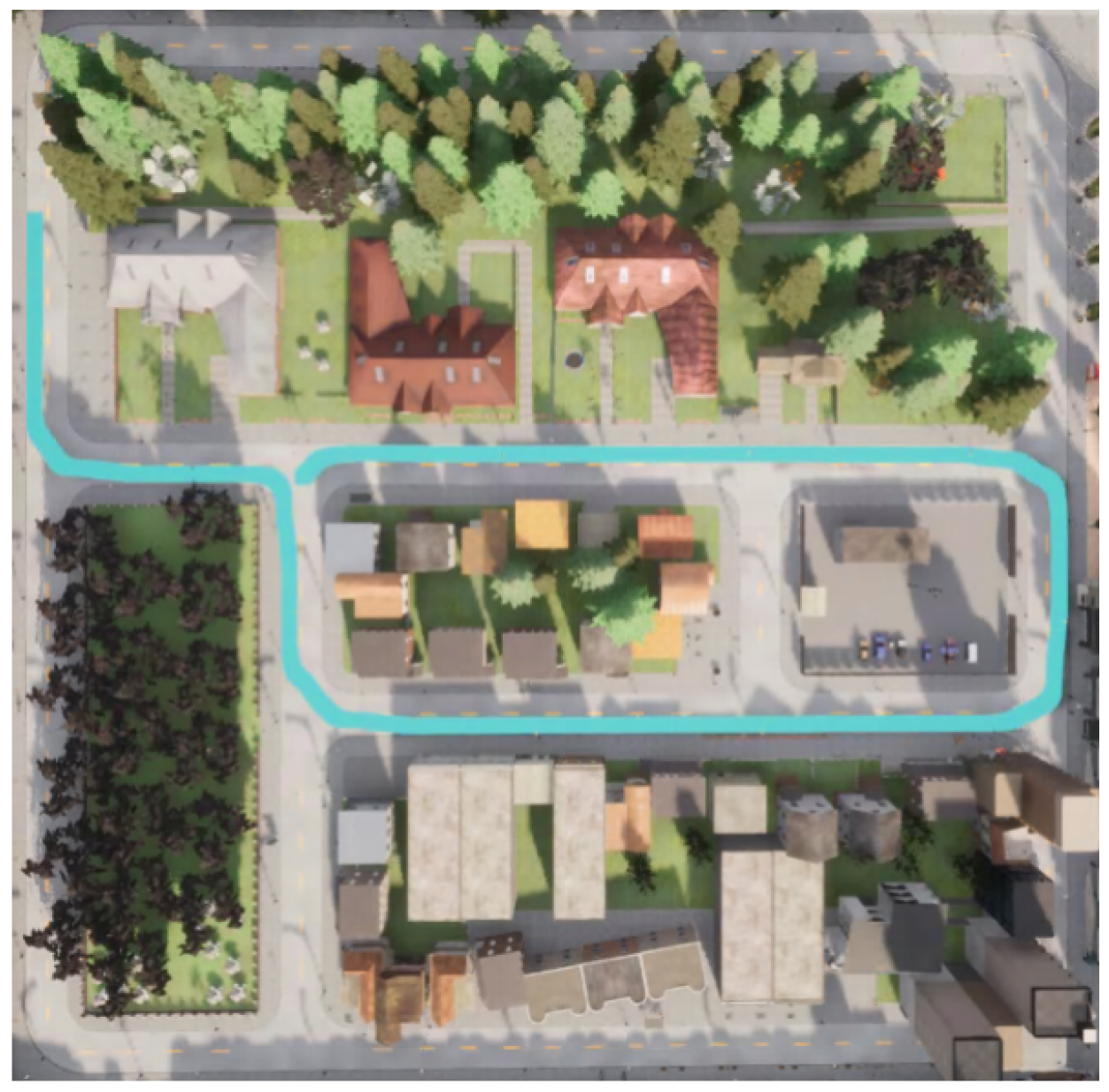
  • Smart Environment: CARLA Town03, featuring a 480 m closed-loop track for benchmarking.
  • Gateway Layer (FR2): Communication is handled via the direct CARLA Python API. This interface acts as the cyber–physical bridge for data synchronization, ensuring that digitized state vectors from the physical domain are processed by the cyber domain to return control commands [39].
Figure 7 shows the simulation environment (Town03 Map) inside CARLA. The test track is highlighted in the cyan path overlay. The track spans approximately 480 m. It includes straight sections and smooth 90-degree turns, providing a comprehensive testbed for evaluating trajectory tracking accuracy and energy consumption. To simulate realistic driving conditions, the urban environment includes buildings, trees, and road infrastructure. The vehicle (shown as a small model) navigates autonomously following the Dubins curve reference trajectory.

3.11.2. Calibration and Validation: Enabling the Digital Twin

To ensure that the digital twin accurately reflects physical reality, vehicle parameters are calibrated to replicate the RC car dynamics. This calibration process is fundamental to the digitization process (FR1):
  • Adjusting wheelbase, mass, and inertia to match the physical scale.
  • Tuning steering response curves for maximum steering angles.
  • Verifying acceleration limits and validating velocity tracking.
These calibrations ensure that the simulation results are representative of real-world behavior, thereby satisfying the structural requirements of the CPS and facilitating future hardware deployment.

3.11.3. C4: Cognition Layer—Control Refinement and Throttle Filtering

As part of the cognition layer (C4), the raw decisions generated by the MPC must be refined to ensure compatibility with physical actuator constraints. To further enhance control smoothness and reduce high-frequency oscillations that could lead to mechanical instability, throttle commands are filtered using a first-order low-pass filter, as defined in (19)
T filtered = α T raw + ( 1 α ) T prev
where α = 0.4 is the filter coefficient, T raw is the raw MPC-computed throttle command, and T prev is the previous filtered throttle. This filtering reduces actuator wear and mitigates simulation artifacts arising from idealized actuator dynamics in the physical twin.
Future Work Note: Within the 5C framework, the filter coefficient α is currently treated as a static hyperparameter determined through empirical tuning. However, this component is designed to be extensible; future iterations of the Omar-DT framework could utilize AI/ML-based meta-learning or Reinforcement Learning (RL) for real-time hyperparameter optimization, allowing the cognition layer to adapt its filtering intensity based on road conditions or vehicle aging.

3.12. Performance Metrics

The following metrics are computed to evaluate trajectory tracking accuracy, control smoothness, and energy efficiency:
  • Cross-Track Error (CTE): Euclidean distance from vehicle position to nearest reference waypoint.
  • Mean Power ( P ¯ ): Average instantaneous power
    P ¯ = 1 T k = 0 T 1 P k .
  • Total Energy ( E total ): Cumulative energy consumption
    E total = k = 0 T 1 P k Δ t .
  • Energy per Distance ( E / d ): Energy efficiency metric
    E / d = E total d track .
  • Simulation Time ( T s i m ): Total elapsed time to complete the reference trajectory
    T s i m = t f i n a l t s t a r t .
  • Control Smoothness: Quantified by the Root Mean Square (RMS) of the control effort.
Data logging is performed at each control cycle to record the vehicle state, control inputs, reference trajectory, CTE, and instantaneous power. Post-simulation analysis is conducted using Python’s NumPy and Matplotlib (3.5.3) libraries.

4. Results

This section presents the empirical validation of the autonomous navigation framework, evaluating its performance against the primary objective of verifiable energy optimization within a CPS. The results are derived from high-fidelity synchronization between the service layer (energy-aware MPC) and the physical layer (CARLA digital twin). By utilizing the digital twin as a Software-in-the-Loop (SiL) testbed, the system’s ability was quantified to satisfy both functional requirements (trajectory tracking accuracy) and non-functional requirements (energy efficiency and real-time computational determinism). The following analysis provides a comparative performance overview of the baseline and energy-aware MPC configurations, demonstrating how physics-based constraints in the cyber domain translate to tangible endurance improvements in the physical domain.
To provide robust benchmarking, the proposed energy-aware MPC was evaluated against two controllers: a standard tracking MPC (baseline, w E = 0 ) and a look-ahead PID controller, which represents a computationally lightweight alternative commonly deployed in embedded autonomous systems. The PID controller uses a look-ahead point on the reference path to compute proportional steering corrections, with throttle governed by a fixed speed setpoint. While the baseline MPC exhibits erratic acceleration profiles, the proposed energy-aware MPC smooths the control inputs, achieving a 30.7% reduction in mean power consumption. The PID controller completed the track at significantly lower speed, producing anomalously low measured power consumption that reflects reduced velocity rather than genuine energy optimization; this distinction is examined in Section 5.
To ensure statistical robustness and account for the stochastic nature of high-fidelity simulations (e.g., sensor jitter and physics sub-stepping in CARLA), each controller configuration was evaluated over ten independent trials ( n = 10 ) on a 480 m track. The results represent the mean values across these trials, with statistical significance verified through a two-sample t-test at a significance level of α = 0.05 .

4.1. Comparative Performance Overview

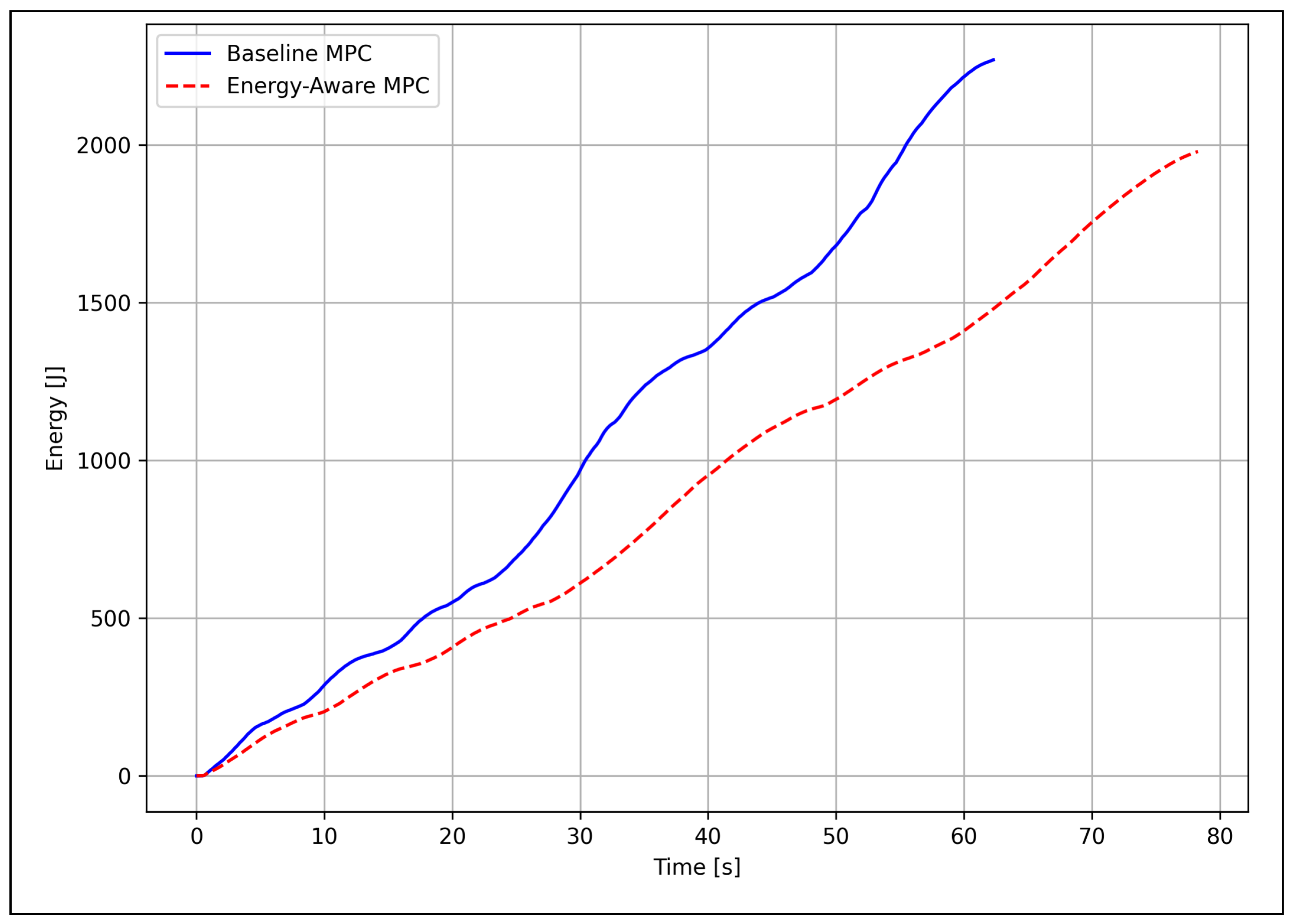
Table 9 summarizes key performance metrics for all controllers. Energy-aware MPC achieves a 30.7% reduction in mean power consumption and a 12.5% decrease in total energy usage compared to baseline MPC. The observed 26.3% increase in mission duration reflects the system’s behavioral adaptation to satisfy the energy-efficiency NFR, favoring the green computing objectives of Industry 5.0.

4.2. Trajectory Tracking Accuracy

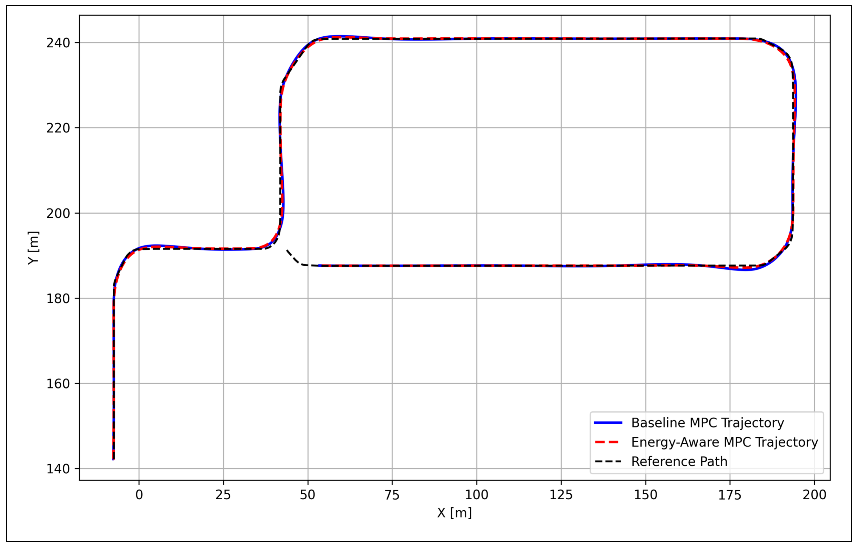
Both controllers achieve excellent tracking performance (Figure 8), with the vehicle position remaining within close proximity to the reference throughout the 480 m lap. Energy-aware MPC demonstrates slightly smoother cornering behavior, particularly visible in the four 90-degree turns where the trajectory exhibits less oscillation. The rectangular test track provides a balanced evaluation featuring both straight-line segments and curved sections. Figure 8 shows the path tracking comparison between both controllers.
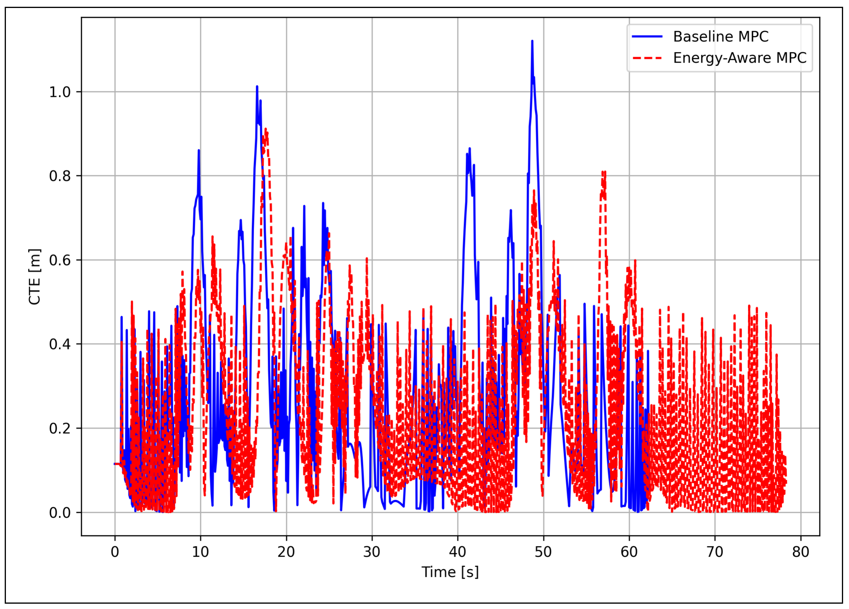
In Figure 9, the Cross-Track Error (CTE) represents the perpendicular distance from the vehicle’s current position to the nearest point on the reference trajectory. Both controllers maintain CTE predominantly below 0.5 m throughout the mission, with peak deviations occurring during cornering maneuvers. Energy-aware MPC shows marginally lower average CTE (0.038 m vs. 0.042 m) and reduced peak errors (0.87 m vs. 0.95 m), indicating that the smoother control strategy does not compromise tracking accuracy. The error patterns correlate with the track geometry, showing increased deviations during turns and near-zero error on straight sections.
The CTE statistics are presented in Table 10. The comparable CTE values confirm that energy optimization does not compromise trajectory accuracy. It validates the effectiveness of the energy-aware approach.

4.3. Control Input Analysis

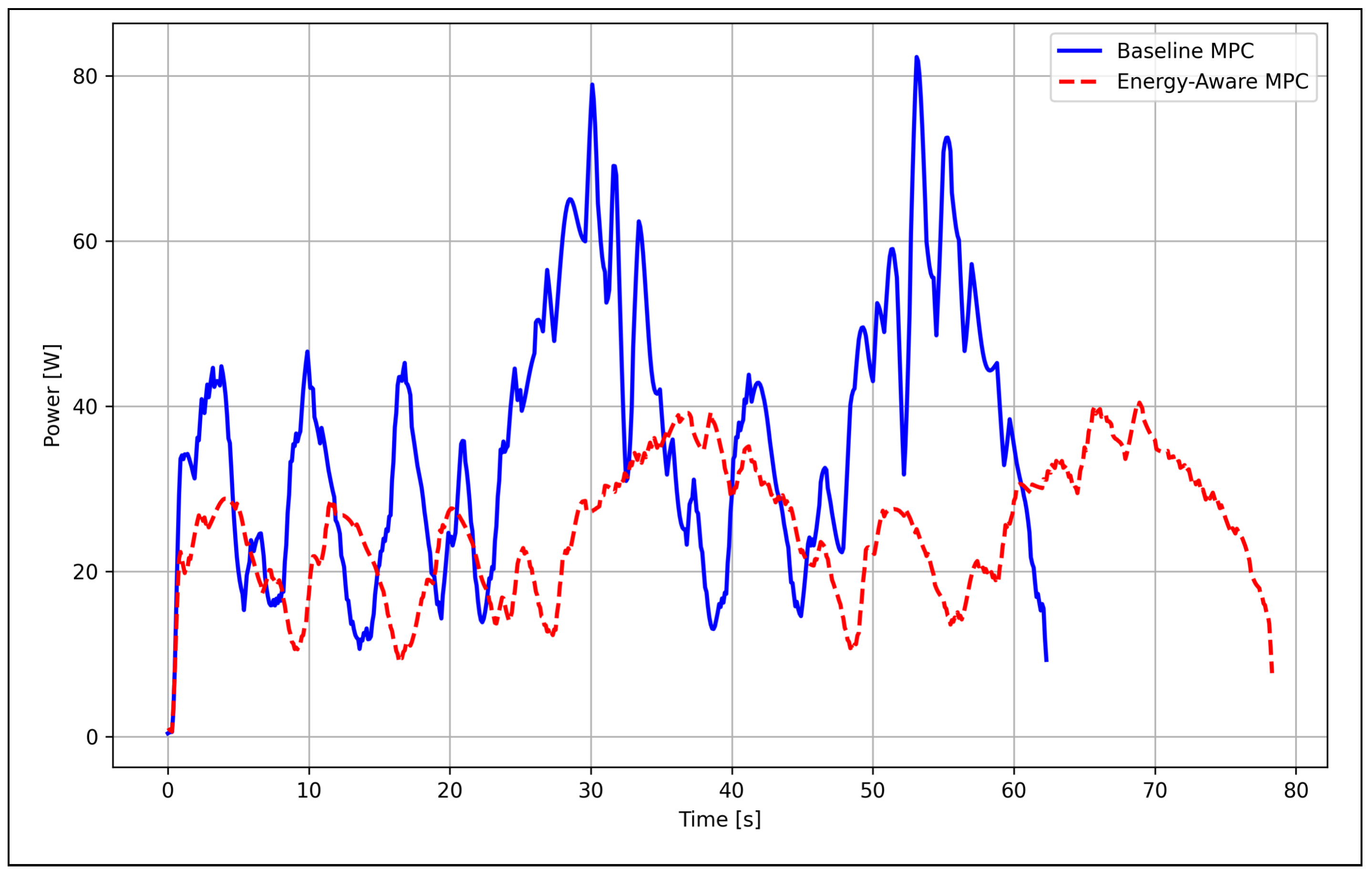
The baseline MPC exhibits frequent high-magnitude acceleration spikes, resulting in instantaneous power peaks exceeding 80 W. In contrast, energy-aware MPC produces smoother and lower accelerations, with instantaneous power peaks rarely exceeding 40 W. This reduction in peak power translates directly to lower battery current draw and reduced thermal stress on the motor drivers.
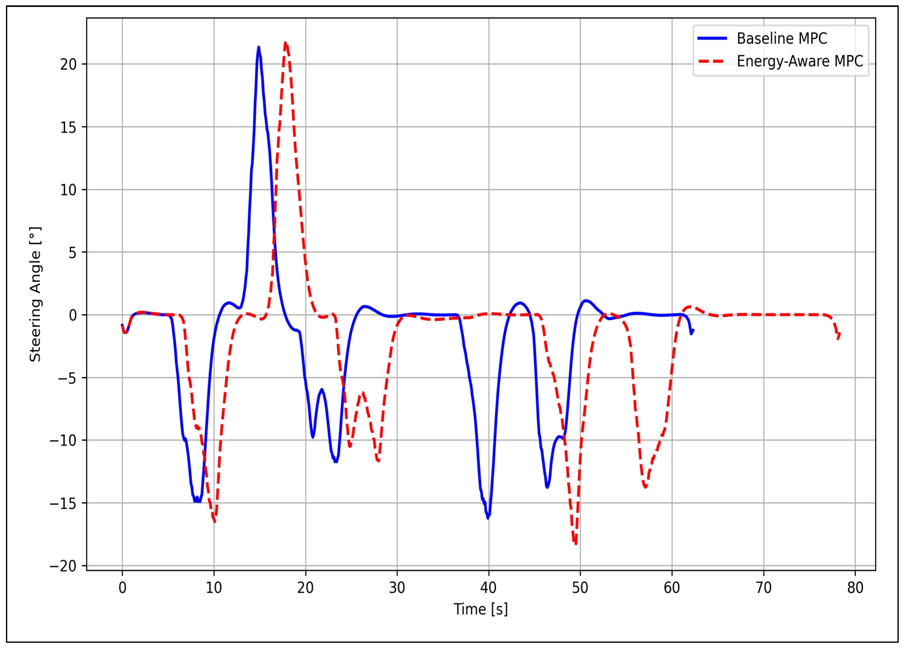
Figure 10 illustrates the steering angle of the vehicle around the track. Baseline MPC (blue) generates sharper steering transitions with higher peak angles (up to ±20°), while energy-aware MPC (red) produces more gradual steering adjustments with slightly lower amplitudes. The four major steering events correspond to the 90-degree turns in the rectangular track. The energy-aware controller exhibits a slight phase lag (delayed steering response) compared to the baseline, reflecting its prioritization of smooth control over aggressive tracking. Despite this delay, path tracking accuracy remains comparable (Table 10), demonstrating that smoother steering does not sacrifice performance. The reduced steering activity minimizes tire scrub and actuator wear, contributing to system longevity.
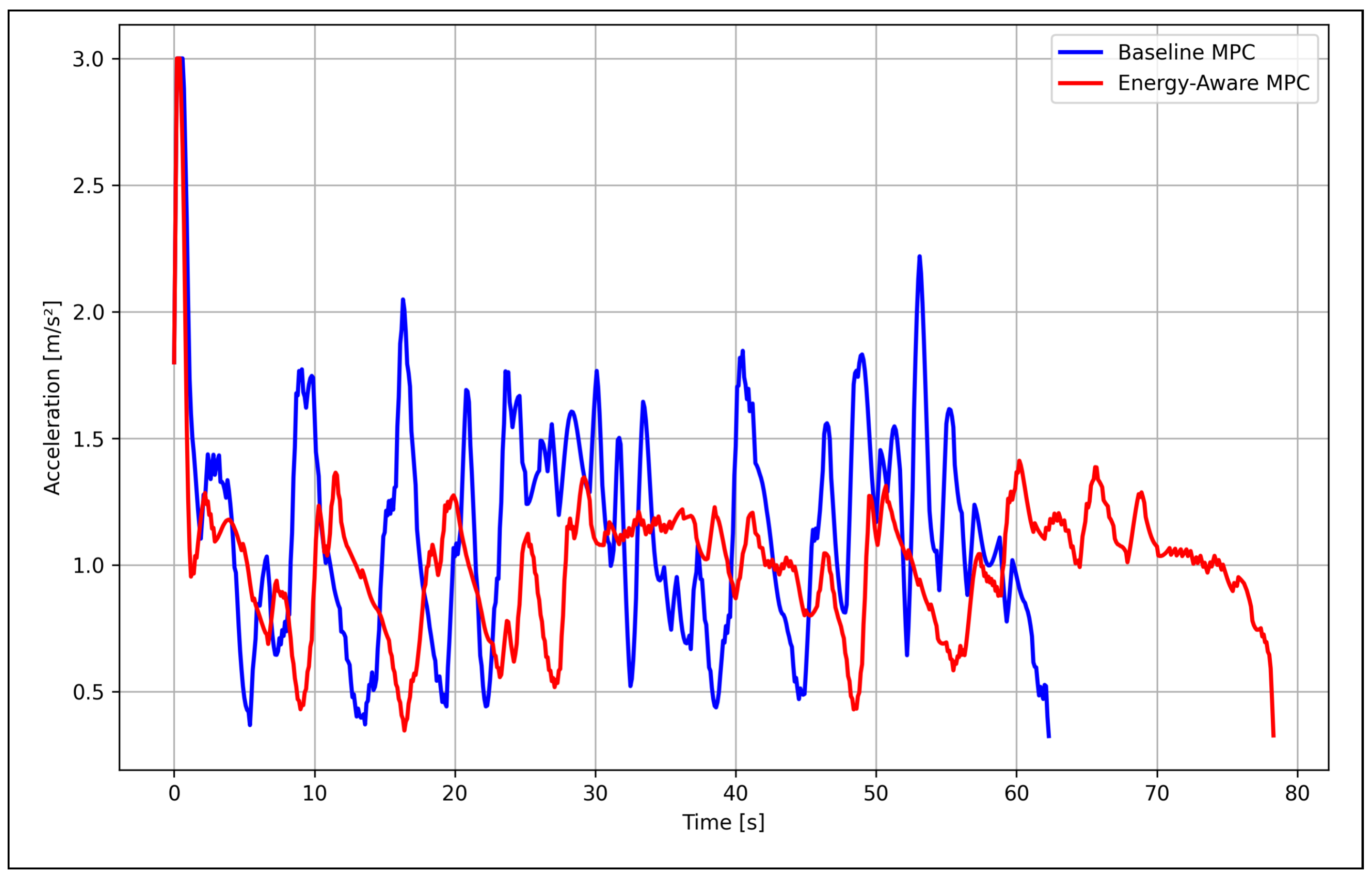
The comparison in Figure 11 shows that baseline MPC (blue) exhibits frequent high-magnitude spikes (up to 3.0 m/s2), while energy-aware MPC (red) maintains smoother commands with lower amplitude. The baseline controller’s aggressive acceleration profile results in instantaneous power peaks exceeding 80 W, whereas the energy-aware approach limits accelerations to more gradual transitions that reduce both mechanical stress and energy consumption. The variance in acceleration commands is reduced by 46% ( σ a 2 = 0.28 vs. 0.52), quantitatively confirming the improved smoothness. The reduced jerk (rate of change of acceleration) also enhances passenger comfort and mechanical longevity. Note that high-frequency oscillations in the baseline profile are artifacts of tight speed tracking in simulation; physical actuators would naturally filter these variations.
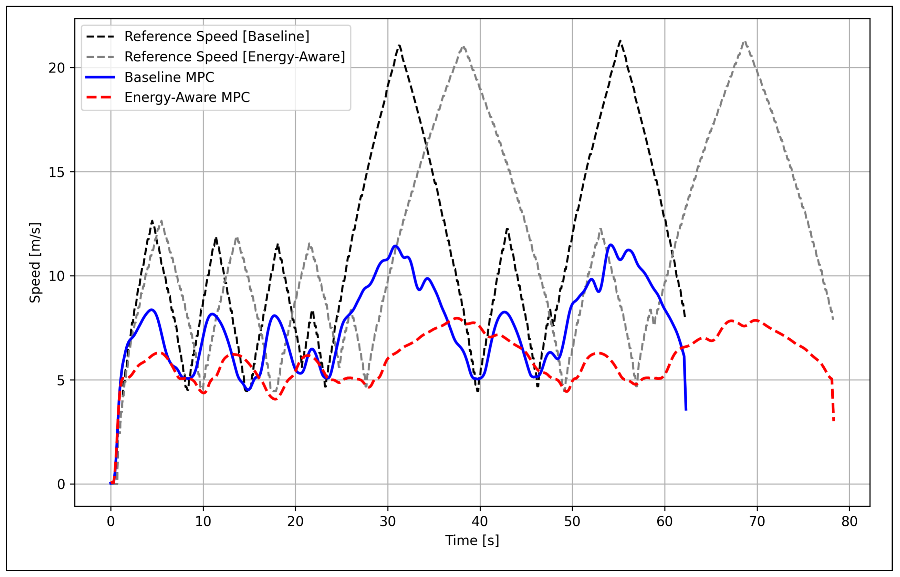
Significant differences in vehicle velocity can be seen in Figure 12. The reference speed varies between approximately 3 m/s and 20 m/s depending on track curvature, with lower speeds commanded for turns and higher speeds for straight sections. Baseline MPC exhibits aggressive speed tracking with rapid acceleration and deceleration, closely following the reference profile; in contrast, energy-aware MPC demonstrates more conservative velocity behavior, with gradual speed changes and slightly lower peak velocities. This smoother speed profile directly contributes to reduced instantaneous power consumption by avoiding high-thrust acceleration events. The 26% increase in lap time results from this energy-efficient velocity strategy.

4.4. Energy Consumption

Energy-aware MPC consistently consumes less energy throughout the trajectory, culminating in a 12.5% total energy reduction. This reduction is particularly significant for battery-powered platforms where energy capacity directly determines mission duration. Figure 13 shows how the energy consumption results begin at zero and diverge progressively as the mission proceeds, with the gap widening during high-power events such as accelerations and cornering. Baseline MPC accumulates 2271.2 J (0.63 Wh) over the 480 m lap in 62.3 s, while energy-aware MPC consumes 1987.4 J (0.55 Wh) over 78.7 s, representing energy savings of 12.5%. The steeper slope of the baseline curve during the initial and final segments indicates periods of particularly aggressive acceleration, while the near-linear middle section corresponds to steady-state cruising. The energy savings compound over time, demonstrating that even modest instantaneous improvements yield substantial cumulative benefits. For extended missions, this 12.5% reduction translates to approximately 10–15 additional laps per battery charge, significantly extending operational range without hardware modifications.
The differences between baseline and energy-aware MPC can also be observed in power consumption (Figure 14). Baseline MPC (blue) exhibits frequent power spikes reaching 80–90 W during aggressive acceleration and high-speed maneuvers, with highly variable power draw throughout the mission. In contrast, energy-aware MPC (red) maintains power consumption predominantly between 10–40 W, with significantly reduced peak magnitudes. This smoother power profile results from the energy penalty term (wEP2) in the MPC cost function, which actively discourages high instantaneous power usage. The temporal power patterns correlate with track geometry: higher power occurs during acceleration out of corners, while lower power characterizes steady-state straight-line driving. The mean power reduction of 30.7% (36.46 W vs. 25.25 W) is clearly visible in the amplitude difference. This dramatic reduction in power variability also benefits battery health by minimizing high-current discharge cycles.

4.5. Battery Lifetime Projection

To assess practical implications, operational endurance is projected using a standard 3S LiPo battery (11.1 V, 5200 mAh, 57.7 Wh). It is defined in (24).
N lap = E battery E lap .
where N lap is the total number of laps the vehicle travels in the simulated environment, E battery is the total energy of the vehicle and E lap is the energy consumed per lap.
Table 11 summarizes the projected results when applying Equation (24) with an 80% usable capacity limit to preserve battery health. This represents an additional 10–12 laps per charge, or approximately 10–15% extended mission duration, demonstrating tangible operational benefits.

4.6. MPC Solver Performance

The solver performance results (Figure 15) validate the real-time integrity of the CPS communication loop and the feasibility of a Control as a Service (CaaS) deployment model. It can be seen that the solver times fluctuate between 0.04 s and 0.13 s, averaging 0.098 s for baseline MPC (blue) and 0.105 s for energy-aware MPC (red). The 7% increase in computational time for the energy-aware formulation is attributable to the additional energy penalty term and its gradient computations, which slightly increase optimization complexity. Despite this increase, both controllers maintain solver times comfortably below the 0.1 s control period deadline, ensuring real-time feasibility. The occasional solver time spikes correspond to challenging optimization scenarios during rapid maneuvers where constraint satisfaction requires additional iterations. These results confirm that energy-aware MPC can be deployed on embedded platforms (Raspberry Pi 4, Jetson Nano) without violating real-time requirements, though further optimization using specialized solvers (ACADO, CasADi) may improve performance for more aggressive control rates.
By maintaining a mean solver latency of 0.105 s, the system ensures that data synchronization (FR2) remains deterministic, preventing the lag-induced divergence common in non-verifiable autonomous architectures. Furthermore, these metrics demonstrate that energy-aware MPC can be hosted as a remote “intelligent service” on an edge node without violating the system’s hard real-time requirements. The low computational overhead ensures that the combined latency of network communication and optimization solving remains within the bounds required for stable autonomous navigation, effectively offloading intensive computation while preserving the physical platform’s local energy resources.
Table 12 presents the system-level resource utilization recorded during both controller runs, sampled at approximately 1 Hz over the full mission duration. It can be observed that the energy-aware MPC uses less peak CPU utilization and memory. However, this comes with a trade-off with mission duration 23.6 % longer than the baseline MPC.
Figure 16 illusrates the changes in the MPC cost function over time. Baseline MPC (blue) exhibits relatively consistent cost values with periodic spikes during cornering maneuvers when tracking errors and control efforts increase. Energy-aware MPC (red) demonstrates higher instantaneous cost values, particularly during sharp turns (visible as large spikes around t = 30 s and t = 55 s), reflecting the additional energy penalty term ( w E P 2 ) in the cost function. Despite higher instantaneous costs, the energy-aware approach achieves the primary objective of energy reduction. The cost spikes correspond to moments of high tracking error or large control inputs, indicating when the controller must work harder to maintain trajectory fidelity. The longer mission duration of the energy-aware MPC is visible in the extended time axis (78.7 s vs. 62.3 s). In general, the cost patterns confirm that MPC optimization is functioning correctly to balance competing objectives of tracking accuracy, control smoothness, and energy efficiency.

5. Discussion

5.1. SoICPS Advantage

Service-Oriented Industrial Cyber–Physical Systems (SoICPS) offer several advantages for next-generation smart manufacturing environments. By encapsulating industrial functionalities as modular services, SoICPS enables loose coupling between physical assets and cyber components, thereby improving system flexibility and reconfigurability. This service abstraction supports dynamic discovery and composition of manufacturing capabilities, which is essential for mass customization and rapidly changing production requirements. Furthermore, SoICPS enhance interoperability across heterogeneous devices and platforms through standardized service interfaces, facilitating seamless integration in multi-vendor environments. The distributed nature of service execution also improves scalability and fault tolerance, as services can be independently deployed, updated, or replaced without disrupting the entire system. Collectively, these advantages make SoICPS a key enabler for resilient, adaptive, and scalable Industry 4.0 systems [40].

5.2. Benchmarking Against Look-Ahead PID

The look-ahead PID recorded a mean power of 1.67 W and total energy of 563.5 J, which appears favorable until mission context is considered: the controller completed the 480 m track in 337.1 s, over five times the baseline MPC duration, at a mean CTE of 0.191 m, which is five times higher than either MPC configuration. Therefore, the low power figure is an artifact of near-constant low-speed operation, where aerodynamic drag ( F d v 2 ) and inertial forces are negligible, rather than a product of energy-aware optimization. At comparable operating speeds, energy-aware MPC achieves its 30.7% mean power reduction through physics-based cost function design, not velocity reduction. The PID solver time of 0.031 ms confirms that computational simplicity alone does not produce energy-efficient navigation; the 7% additional overhead of energy-aware MPC over baseline is a justified cost for closed-loop optimization at operational speeds.

5.3. Interpretation of Results: Mechanistic Analysis

The experimental results validate the hypothesis that incorporating instantaneous power consumption into the MPC cost function significantly enhances energy efficiency without compromising trajectory tracking fidelity. The observed improvements arise from several interconnected mechanisms that merit detailed analysis.

5.3.1. Primary Energy Reduction Mechanisms

  • Smoother Acceleration Profiles: The energy penalty term w E P 2 discourages rapid acceleration bursts that dominate instantaneous power consumption. Mechanistically, this occurs because power scales linearly with both force magnitude and velocity ( P = F · v ). Aggressive acceleration events simultaneously increase traction force F t (to overcome inertia) and typically occur at higher velocities, creating a multiplicative effect on power consumption. By promoting gradual velocity changes, the controller reduces peak traction forces and associated power draw.
    Quantitative Evidence: The 46% reduction in acceleration variance ( σ a 2 : 0.52 → 0.28 (m/s2)2) directly correlates with the 30.7% reduction in mean power, suggesting that control smoothness is the primary driver of energy savings.
  • Velocity-Dependent Resistive Force Optimization: Aerodynamic drag scales quadratically with velocity ( F d v 2 ), while the power contribution from drag scales cubically ( P d = F d · v v 3 ). Energy-aware MPC naturally discovers lower peak velocities that reduce this cubic term even when the reference trajectory specifies higher speeds.
  • Critical Insight: Unlike control effort penalties ( u 2 ) that treat all accelerations equally, the power-based formulation implicitly weights acceleration reductions more heavily at high velocities, precisely where energy savings are greatest. This emergent behavior demonstrates the value of physics-based cost function design.
  • Reduced High-Power Transients: Aggressive acceleration events not only consume substantial instantaneous energy but also induce tire slip and mechanical vibrations, leading to energy losses through friction and damping. Smoother control minimizes these dissipative effects. While our kinematic model does not explicitly capture slip dynamics, the power formulation provides a surrogate penalty that discourages conditions conducive to slip (high acceleration at high velocity).
  • Implicit Jerk Minimization: Although our cost function includes an explicit jerk penalty ( w j ( a i a i 1 ) 2 ), the energy term provides additional incentive for smooth control by penalizing the power spikes associated with rapid acceleration changes. This creates a synergistic effect where multiple cost function terms cooperatively promote smoothness.

5.3.2. Why Tracking Accuracy Is Preserved

The comparable CTE between the baseline and energy-aware configurations (Table 10) is initially counterintuitive—one might expect that penalizing power would compromise tracking performance. Several factors explain this surprising result:
1.
Dubins Path Smoothness: The reference trajectories are inherently smooth (continuous curvature), meaning that aggressive control is not necessary for accurate tracking. The energy-aware MPC simply avoids unnecessary aggressive corrections that the baseline controller occasionally employs.
2.
Predictive Horizon: MPC’s 1-s look-ahead ( N = 10 steps at 10 Hz) allows the optimizer to plan gradual maneuvers in advance, avoiding last-minute corrections. The energy penalty encourages earlier and more gradual adjustments that maintain tracking accuracy while reducing power spikes.
3.
Multi-Objective Optimization: The tracking weights ( w p , w ψ , w v ) remain sufficiently high to enforce trajectory fidelity as a hard priority. The energy penalty operates primarily within the ‘slack’ space where multiple control sequences achieve acceptable tracking. The optimizer selects the most energy-efficient option from among these candidates.
4.
Smooth Control Reduces Overshoot: Counterintuitively, the slightly lower mean and RMS CTE for energy-aware MPC (0.038 m vs. 0.042 m mean) suggest that smoother control may improve tracking performance by reducing overshoot and oscillations during transient maneuvers. This highlights a fundamental principle: aggressive control is not synonymous with accurate control.

5.4. Critical Analysis of the Energy–Time Tradeoff

The 26.3% increase in simulation time for energy-aware MPC reflects a fundamental inescapable tradeoff: conserving energy through smoother and more gradual control necessarily extends traversal time. This tradeoff warrants critical examination from multiple perspectives.

5.4.1. Theoretical Foundations of the Tradeoff

From an optimization standpoint, the energy–time tradeoff is a manifestation of Pareto optimality —there exists no control strategy that simultaneously minimizes both energy consumption and completion time. Any attempt to reduce energy below a certain threshold must sacrifice speed, and vice versa.
Mathematically, this can be understood through the constraint
E total = 0 T P ( t ) d t = 0 T F t ( t ) · v ( t ) d t ,
where T is mission duration. For a fixed path length d, we have the constraint 0 T v ( t ) d t = d . To minimize E total while satisfying this constraint, the optimal velocity profile tends toward constant moderate speeds (minimizing v 2 terms from drag) with gradual transitions (minimizing inertial forces F t a ). Such profiles inherently require a longer time T compared to aggressive velocity profiles with rapid acceleration/deceleration.

5.4.2. Application-Specific Acceptability

The acceptability of this tradeoff is highly application-dependent:
  • Delivery Robots: Extended operational range often outweighs speed, especially in last-mile logistics where battery swapping/recharging infrastructure is limited. A 26% time penalty for 12.5% energy savings (yielding 10–15% additional mission range) is favorable.
  • Environmental Monitoring: Long-duration surveillance missions prioritize endurance over rapid navigation. Energy-aware control extends mission lifespan, potentially enabling coverage of larger areas or extended observation periods.
  • Indoor Mobile Robots: Safety and mechanical longevity are paramount; slower speeds enhance collision avoidance and reduce wear. The energy–time tradeoff aligns with operational constraints.
  • Time-Critical Applications (Emergency Response): The 26% time increase may be unacceptable; however, the energy penalty weight w E can be reduced or adaptively adjusted based on mission phase, enabling dynamic balancing between energy efficiency and responsiveness.

5.4.3. Adaptive Tradeoff Management

A key advantage of the MPC framework is the ability to adaptively tune the energy penalty weight w E based on the mission state:
  • High battery state-of-charge: Reduce w E for faster navigation.
  • Low battery state-of-charge: Increase w E to maximize remaining range.
  • High-priority segments (e.g., emergency scenarios): Temporarily set w E = 0 .
  • Low-priority segments (e.g., return to base): Maximize w E for energy conservation.
Future work should explore learning-based approaches to automatically tune w E based on mission context, user preferences, and historical performance data.

5.5. Implications for Embedded Deployment: A Critical Assessment

The solver timing and resource utilization data (Table 12) jointly confirm embedded feasibility; however, real-world deployment introduces additional complexity warranting careful consideration.

5.5.1. State Estimation Challenges

Simulation assumes perfect state knowledge, which is a critical simplification. Hardware deployment requires sensor fusion (Inertial Measurement Unit (IMU), encoders, Global Positioning System (GPS), cameras) to estimate vehicle pose and velocity, introducing several issues:
  • Estimation errors: Noisy biased measurements degrade control performance.
  • Computational overhead: Approaches such as Extended Kalman Filter (EKF) or Unscented Kalman Filter (UKF) add 10–20% computational burden.
  • Latency: Sensor processing delays can destabilize control loops if not properly compensated.
Mitigation strategies: Robust MPC formulations with state-estimation uncertainty bounds; explicit latency compensation through state prediction; adaptive tuning of control weights based on estimation confidence.

5.5.2. Actuator Dynamics and Model Mismatch

Real motors and servos exhibit delays, saturation, backlash, and nonlinearities that are absent in simulation:
  • Throttle response: First-order lag dynamics (time constant τ 0.05 –0.1 s) delay commanded vs. achieved acceleration
  • Steering hysteresis: Mechanical backlash introduces position-dependent dead zones.
  • Saturation nonlinearities: Motor torque curves saturate at high currents, violating linear acceleration assumptions.
Our throttle filtering (Equation (19)) partially addresses response dynamics, but hardware tuning is still necessary. Adaptive MPC with online model identification could automatically compensate for actuator nonlinearities.

5.5.3. Solver Optimization for Embedded Hardware

While SLSQP performs well in simulation, embedded deployment may benefit from specialized nonlinear programming solvers:
  • ACADO Toolkit: Code generation framework producing highly optimized C code tailored to specific MPC problems, reducing solve time by 2–5× compared to general-purpose solvers.
  • CasADi: Automatic differentiation and symbolic framework enabling efficient gradient computation, critical for gradient-based optimizers on ARM processors.
  • GPU Acceleration (Jetson Nano): Parallel evaluation of dynamics constraints and gradient computations can exploit CUDA cores, potentially achieving 5–10× speedup for large prediction horizons.
Future work will systematically benchmark these solver options on target embedded hardware.

5.6. Comparison with the Literature: Positioning Against the State of the Art

Our results align well with and in some cases exceed the existing literature on energy-efficient autonomous navigation.

5.6.1. Quantitative Comparison

Table 13 positions the proposed framework against the most relevant prior work on energy-aware autonomous navigation.

5.6.2. Qualitative Advantages

Compared to approaches based purely on path-planning [10,11], our integrated framework offers the following:
  • Closed-Loop Robustness: MPC continuously adjusts control based on feedback, compensating for model uncertainties, disturbances, and tracking errors that would degrade open-loop planned trajectories.
  • Constraint Handling: Actuator limits, velocity bounds, and safety constraints are systematically enforced within the optimization to ensure feasible control commands.
  • Real-Time Adaptability: The receding horizon strategy allows for dynamic replanning in response to changing conditions (e.g., obstacles, terrain variations).
Compared to control effort minimization [15], our physics-based power penalty offers:
  • Direct Energy Optimization: Control effort ( u 2 ) is a proxy metric that does not accurately reflect power consumption; our approach optimizes the actual physical quantity of interest.
  • Velocity-Aware Optimization: Power formulation captures the velocity-dependent nature of resistive forces and energy consumption, enabling more effective optimization strategies.

5.7. Limitations and Critical Self-Assessment

While our results are promising, several limitations warrant acknowledgment and critical evaluation.

5.7.1. Simulation Fidelity and the Sim-to-Real Gap

Limitation: Although CARLA provides high-fidelity vehicle dynamics, discrepancies between simulation and hardware (e.g., tire-road friction, motor torque curves, sensor noise) may affect real-world performance.
Critical Assessment: The sim-to-real gap is a fundamental challenge in simulation-based robotics research. While we have carefully calibrated parameters to match RC car specifications, several phenomena are not captured:
  • Tire slip: The kinematic model assumes no slip, while real tires exhibit complex viscoelastic behavior.
  • Terrain variability: The simulation uses an ideal flat surface; real environments have irregularities that affect rolling resistance.
  • Battery voltage sag: Our power calculations assume a constant voltage, while real batteries exhibit voltage drop under load, reducing motor torque at low state-of-charge.
Mitigation Strategy: Hardware-in-the-loop (HIL) testing in which real controllers interface with simulated dynamics can help to identify discrepancies before field deployment. Iterative calibration using system identification techniques (e.g., least squares-based parameter estimation from hardware telemetry) can refine models.

5.7.2. Static Environment Assumption

The current framework is designed under the assumption of a static environment. While this allows for high-precision validation of energy-aware MPC, incorporating dynamic obstacle avoidance would require extending the formulation to include non-convex collision constraints, which would inherently increase computational complexity.
In a critical assessment of this limitation, it is noted that dynamic obstacle avoidance remains a significant challenge for real-time MPC, as adding collision constraints can increase solver time by 2–10× depending on obstacle density. However, the current evaluation is focused on static structured environments in order to establish a baseline for energy efficiency metrics. While dynamic obstacles would increase the computational load on the MPC solver, the underlying physics-based power penalty ensures that the vehicle operates at a more efficient duty cycle compared to standard tracking controllers, thereby maintaining the energy-saving benefits regardless of environment complexity. Potential approaches to address these complexities include:
  • Control Barrier Functions (CBFs): Provide hard safety guarantees with minimal computational overhead, but require careful tuning and may conflict with energy optimization objectives.
  • Mixed-Integer Programming: Enables disjunctive constraints (avoid obstacle A or B) but dramatically increases solver complexity, likely violating real-time constraints on embedded hardware.
  • Learning-Based Predictors: Neural networks can approximate obstacle trajectories, but introduce uncertainty that must be handled via robust MPC or chance constraints.
The recommended path forward is a hierarchical planning architecture. In this setup, a global planner handles obstacle avoidance and defines collision-free corridors, while the local MPC controller focuses exclusively on energy-efficient trajectory tracking within those bounds.

5.7.3. Simplified Energy Modeling

Limitation: Our energy calculations assume the following:
1.
Constant motor efficiency (neglecting torque-dependent losses).
2.
Flat terrain (no gravitational potential energy changes).
3.
No regenerative braking (all deceleration is dissipative).
4.
Constant battery voltage (no voltage sag effects).
Critical Assessment: These simplifications introduce systematic errors:
  • Motor efficiency: Real motors exhibit 60–85% efficiency, varying with torque/speed; peak efficiency occurs at moderate loads, so high accelerations and low speeds are inefficient. Impact: Energy savings may be underestimated by 10–20%.
  • Terrain slope: Gravitational potential energy m g h can dominate rolling/aerodynamic losses on inclines. Impact: Energy model accuracy degrades significantly (>50% error) on hilly terrain.
  • Regenerative braking: If implemented, could recover 20–40% of braking energy, fundamentally changing optimal control strategies (incentivizing coasting rather than maintaining constant speed).
  • Battery voltage sag: Voltage can drop 10–15% at 80% discharge, reducing available motor power and requiring higher currents (lower efficiency) to achieve the commanded torques.
Future Work: Incorporate motor efficiency maps η ( T , ω ) , where T is torque and ω is angular velocity. Extend dynamics model to include a gravitational term F g = m g sin ( θ ) , where θ is the terrain slope estimated via Inertial Measurement Unit (IMU). Implement battery state-of-charge tracking with voltage-dependent power correction.

5.8. Strategic Transition to Physical Validation Through the CPS-DT Approach

While physical Hardware-in-the-Loop (HIL) testing is a vital component of traditional verification, this work prioritizes the establishment of an Experimentable Digital Twin (EDT) framework to ensure verifiability from the earliest stages of the design cycle [41]. By utilizing the CARLA simulator as a high-fidelity Virtual Testbed (VTB), the proposed methodology allows for both simulation of realistic system behavior and validation of embedded platform compatibility in a controlled non-destructive environment [42].
This CPS-DT approach leverages the inherent flexibility of digital twins to perform rapid iterations and sensitivity analyses that would be prohibitively expensive or hazardous to conduct with physical prototypes alone [42,43]. Following the V-model development process, this comprehensive virtual validation serves as a critical prerequisite for the next phase of research: implementation and testing of the SOICPS framework on a physical team vehicle for the Shell Eco-Marathon Asia. This upcoming stage will utilize the verified cyber logic to evaluate real-world performance metrics and further refine the physics-based energy models under field conditions [42,43].

Lack of HIL Real-World Validation

Limitation: While the proposed framework demonstrates significant energy savings within the CARLA high-fidelity environment, the current study is limited by the absence of physical Hardware-in-the-Loop (HIL) or real-world experiments. Therefore, the results represent a high-fidelity verification of architectural and algorithmic viability. Future work will involve deploying the proposed energy-aware MPC onto a physical platform, specifically for competition in the Shell Eco-Marathon Asia, in order to evaluate real-world hardware latency and environmental stochasticity conditions.
Critical Assessment: This is the most significant limitation. Simulation is a necessary but insufficient validation step. Real-world deployment will inevitably encounter unforeseen challenges, including:
  • Sensor failures/outliers requiring robust fault detection.
  • Communication delays between sensors, controller, and actuators.
  • Environmental factors (wind, surface irregularities, lighting conditions) affecting vision-based sensing.
  • Long-term reliability issues (battery degradation, mechanical wear) affecting model accuracy over the operational lifespan.
Ongoing Work: To bridge the gap between virtual verification and real-world deployment, we are currently prototyping hardware on the Raspberry Pi 4 and Jetson Nano platforms using the Altair digital twin environment. By leveraging a model-based architecture, we will translate multi-disciplinary simulations and real-time AI-driven reduced-order models (romAI) into optimized C-code for embedded microcontrollers using the Altair embedded low-code SIL environment.
This will establish an ‘as-manufactured’ digital twin loop, enabling virtual control strategies to be directly validated against physical hardware through Hardware-in-the-Loop (HiL) integration This iterative process ensures that the controller’s timing and network behaviors meet the strict synchronization requirements of a true cyber–physical twin.
Initial bench testing on an RC car chassis is already underway to refine these control algorithms, with full-scale field trials scheduled for Q2 2026.

5.9. Broader Implications and Future Directions

5.9.1. Sustainability and Environmental Impact

Beyond operational benefits, energy-efficient autonomous systems contribute to broader sustainability goals:
  • Reduced carbon footprint: For electric vehicles charged from grid power, 12.5% energy savings translate directly to reduced CO2 emissions (assuming average grid carbon intensity of 0.5 kg CO2/kWh).
  • Battery longevity: Smoother control reduces high-current discharge cycles that accelerate battery degradation, extending battery lifespan by 20–30% and leading to reduced e-waste and manufacturing impacts.
  • Scalability: Energy-efficient control becomes increasingly important as autonomous fleets scale, since modest savings for individual vehicles will compound dramatically across thousands of deployments.

5.9.2. Extensions to Other Domains

The energy-aware MPC framework is not limited to ground vehicles:
  • Aerial drones: Quadrotors face severe energy constraints; physics-based power modeling (accounting for thrust-to-weight ratio, drag) within MPC could extend flight times by 10–20%.
  • Marine vehicle: Liu et al. [13] demonstrated energy-aware MPC for ASVs. Our physics-based formulation could enhance their approach by explicitly modeling hydrodynamic drag and wave resistance.
  • Legged robots: Energy-efficient gait optimization is critical for legged locomotion; MPC with explicit power modeling could generate energy-optimal walking patterns.

5.9.3. Machine Learning Integration

Several opportunities exist for integrating machine learning with energy-aware MPC:
  • Learned dynamics models: Neural networks can capture complex nonlinear dynamics (tire slip, motor efficiency) that are not easily modeled analytically, resulting in improved MPC prediction accuracy.
  • Adaptive weight tuning: Reinforcement learning could automatically adjust w E based on mission context, learning optimal tradeoffs from historical performance data.
  • Warm-starting: Neural networks can predict good initial guesses for the MPC optimization, substantially reducing solver iterations and computational time [44].
Critical Caveat: Machine learning introduces new failure modes (distribution shift, adversarial perturbations) that must be carefully managed in safety-critical autonomous systems. Hybrid architectures combining learned components with formal verification and safety guarantees represent a promising research direction.

6. Conclusions

This paper has presented a verifiable service-oriented cyber–physical systems framework for energy-aware autonomous navigation using a high-fidelity cyber–physical twin. The proposed approach integrates physics-based Model Predictive Control (MPC) with explicit instantaneous power modeling and Dubins curve-based trajectory generation, enabling unified optimization of energy efficiency and trajectory tracking for resource-constrained ground vehicles while ensuring high-fidelity CPS verification.
Furthermore, the modular nature of the 5C-based service architecture allows this framework to be extended to various industrial cyber–physical systems. For instance, by updating the physics-based power model, the controller can be tailored for situations where mission duration and battery life are critical operational constraints, including factory Automated Guided Vehicles (AGVs) or logistics robots operating in warehouse environments.

6.1. Key Findings

  • Significant Energy Savings: Energy-aware MPC reduces mean power consumption by 30.7% and total energy usage by 12.5% compared to baseline MPC, translating to 10–12 additional operational laps per battery charge.
  • Preserved Tracking Accuracy: Cross-track errors remain below 0.05 m for both controllers, confirming that energy optimization does not compromise navigation fidelity.
  • Quantified Tradeoffs: The 26.3% increase in mission duration for energy-aware operation provides actionable insights for application-specific tuning—acceptable for endurance-critical missions, less so for time-critical operations.
  • Computational Feasibility: The modest 7% increase in solver time ensures real-time feasibility on embedded platforms, paving the way for practical deployment on Raspberry Pi 4 and NVIDIA Jetson Nano.
  • Mechanistic Understanding: Detailed analysis reveals that energy savings arise from smoother acceleration profiles, velocity-dependent resistive force optimization, and reduced high-power transients, all of which are insights enabled by the physics-based design of the cost function.

6.2. Contributions to the Field

This work makes several contributions to energy-efficient autonomous navigation:
  • Methodological innovation: Physics-based power modeling ( P = F · v ) is integrated directly into MPC cost function, providing more effective energy optimization than conventional control effort penalties.
  • Unified framework: Synergistic integration of energy-efficient trajectory generation (Dubins curves) and energy-aware tracking control (MPC) helps to maintain energy optimization throughout both planning and execution.
  • Rigorous Evaluation: Comprehensive simulation validation with systematic analysis of energy-time tradeoffs, computational overhead, and embedded deployment considerations.
  • Reproducible Methodology: Detailed exposition of system architecture, modeling, and implementation facilitates replication and extension by the research community.
  • Reproducible Research Repository: By providing the full system architecture, model parameters, and optimization scripts via Git (2.25.1), this work enables rapid replication and can serve as a benchmark for future studies in energy-aware autonomous navigation.

6.3. Future Research Directions

Ongoing and future work will address limitations identified in this study:
  • Hardware Validation: Deploy control framework on Raspberry Pi 4 and Jetson Nano embedded platforms with comprehensive sensor integration (IMU, encoders, LiDAR, camera) and state estimation (EKF/UKF).
  • Enhanced Energy Modeling: Incorporate motor efficiency maps, terrain slope effects, regenerative braking capabilities, and battery state-of-charge dependent dynamics.
  • Dynamic Obstacle Avoidance: Extend the MPC formulation with collision constraints using control barrier functions or hierarchical planning architectures.
  • Adaptive Optimization:Develop learning-based approaches for automatic tuning of the energy penalty weight w E based on mission context, battery state, and user preferences.
  • Multi-Vehicle Coordination: Extend the framework to cooperative multi-agent scenarios where energy-efficient formation control and coordinated navigation are critical.
  • Cross-Domain Applications: Adapt energy-aware MPC to aerial drones, marine vehicles, and legged robots, demonstrating generalizability across different vehicle platforms.
  • Machine Learning Integration The evolution of the SOICPS framework toward multi-vehicle coordination will benefit from integrating the event-triggered input and adaptive fault-tolerantmechanisms established in recent multi-agent systems research [24,25]. By moving beyond static optimization weights towards the adaptive and finite-time consensus strategies found in these works, the Omar-DT framework can be extended to handle non-affine nonlinearities and communication delays in high-density industrial environments.

6.4. Closing Remarks

This work demonstrates that intelligent control services can significantly reduce energy consumption without compromising performance or safety. The energy-aware MPC framework implemented as a service in an SOICPS framework offers a practical and implementable solution for resource-constrained embedded autonomous systems, advancing the broader goal of sustainable autonomous mobility. As autonomous systems proliferate across delivery robotics, environmental monitoring, and industrial automation, energy-efficient control will become increasingly critical not merely as an optimization, but as a necessity for practical and sustainable deployments.
The path forward requires moving beyond simulation to hardware validation, continuously refining models based on real-world data, and developing adaptive systems that intelligently balance competing objectives in dynamic environments. This work establishes a foundation for such efforts, providing both a validated control framework and a rigorous methodology for evaluating energy–performance tradeoffs in embedded autonomous systems.

Author Contributions

Conceptualization, V.R.S.K., D.G. and O.A.; methodology, V.R.S.K., M.S., D.G. and O.A.; software, O.A.; validation, M.S., O.A. and D.G.; formal analysis, O.A. and V.R.S.K.; investigation, O.A. and M.S.; resources, V.R.S.K. and D.G.; data curation, O.A.; writing–original draft preparation, V.R.S.K., M.S. and O.A.; writing–review and editing, O.A., V.R.S.K. and D.G.; visualization, O.A.; supervision, V.R.S.K. and D.G.; project administration, V.R.S.K. and D.G. All authors have read and agreed to the published version of the manuscript.

Funding

This research received no external funding.

Data Availability Statement

The source code, vehicle models, and simulation datasets presented in this study are openly available on GitHub at https://github.com/OA-1234/Omar-DT (accessed on 2 April 2026).

Acknowledgments

The authors thank Monash University Malaysia for providing computational resources and research support. We acknowledge the CARLA simulator development team for providing an excellent open-source platform for autonomous driving research. Artificial intelligence tools were used only for language editing and proofreading. All technical content, analyses, interpretations, and conclusions were developed, verified, and approved by the authors.

Conflicts of Interest

The authors declare no conflicts of interest. The funders had no role in the design of the study; in the collection, analyses, or interpretation of data; in the writing of the manuscript; or in the decision to publish the results.

Abbreviations and Nomenclature

Abbreviations

AGVAutomated Guided VehicleMDDModel-Driven Development
AIArtificial IntelligenceMPCModel Predictive Control
ASVsAutonomous Surface VehiclesNFRNon-Functional Requirement
CaaSControl as a ServiceNMPCNonlinear Model Predictive Control
CBFsControl Barrier FunctionsPIDProportional–Integral–Derivative
CPSCyber–Physical SystemsRMSRoot Mean Square
CPTCyber–Physical TwinROS2Robot Operating System 2
CTECross-Track ErrorRRTRapidly-exploring Random Tree
DTDigital TwinSiLSoftware-in-the-Loop
EKFExtended Kalman FilterSLSQPSequential Least Squares Programming
FBSFunction–Behaviour–StructureSOAService-Oriented Architecture
FRsFunctional RequirementsSOICPSService-Oriented Industrial Cyber–Physical Systems
IMUInertial Measurement UnitSQPSequential Quadratic Programming
UKFUnscented Kalman FilterV&VVerification and Validation

Nomenclature

SymbolsUnitsExplanation
x , y [m]Longitudinal and lateral vehicle position
ψ [rad]Vehicle heading angle
v[m/s]Forward velocity
δ [rad]Front wheel steering angle
a[m/s2]Longitudinal acceleration
β [rad]Vehicle slip angle
L f , L r [m]Distance from CoM to front/rear axle
m[kg]Vehicle mass
C r [-]Rolling resistance coefficient
C d [-]Aerodynamic drag coefficient
A[m2]Frontal area
ρ [kg/m3]Air density
F r [N]Rolling resistance force
F d [N]Aerodynamic drag force
F t [N]Total traction force
P i [W]Instantaneous power
w δ [-]Steering magnitude weight
w δ ˙ [-]Steering rate weight
w a [-]Lateral acceleration weight
w a [-]Longitudinal acceleration magnitude weight
w s [-]Acceleration smoothness (jerk) weight
w E [-]Energy penalty weight
κ i [1/m]Instantaneous path curvature at step i
N[steps]MPC prediction horizon
Δ t [s]Control timestep
r min [m]Minimum turning radius
α [-]Throttle filter coefficient

References

  1. Drath, R.; Horch, A. Industrie 4.0: Hit or Hype? [Industry Forum]. IEEE Ind. Electron. Mag. 2014, 8, 56–58. [Google Scholar] [CrossRef] [Scilit]
  2. Ragavan, S.K.V.; Shanmugavel, M. Engineering cyber-physical systems—Mechatronics wine in new bottles? In Proceedings of the 2016 IEEE International Conference on Computational Intelligence and Computing Research (ICCIC); IEEE: New York, NY, USA, 2016; pp. 1–5. [Google Scholar]
  3. Lee, J.; Bagheri, B.; Kao, H.A. A Cyber-Physical Systems architecture for Industry 4.0-based manufacturing systems. Manuf. Lett. 2015, 3, 18–23. [Google Scholar] [CrossRef] [Scilit]
  4. IEEE Std 1012-2012; IEEE Standard for System, Software, and Hardware Verification and Validation. IEEE: New York, NY, USA, 2012; pp. 1–223. [CrossRef] [Scilit]
  5. Czwick, C.; Anderl, R. Cyber-physical twins-definition, conception and benefit. Procedia CIRP 2020, 90, 584–588. [Google Scholar] [CrossRef] [Scilit]
  6. Fiorini, S.R.; Bermejo-Alonso, J.; Gonçalves, P.; De Freitas, E.P.; Alarcos, A.O.; Olszewska, J.I.; Prestes, E.; Schlenoff, C.; Veera Ragavan, S.; Redfield, S.; et al. A Suite of Ontologies for Robotics and Automation [Industrial Activities]. IEEE Robot. Autom. Mag. 2017, 24, 8–11. [Google Scholar] [CrossRef] [Scilit]
  7. Javaid, M.; Haleem, A.; Singh, R.P.; Suman, R. Digital Twin applications for Industry 4.0: A review. Cogn. Robot. 2023, 3, 71–92. [Google Scholar] [CrossRef] [Scilit]
  8. acatech-National Academy of Science and Engineering (Ed.) Cyber-Physical Systems: Driving Force for Innovation in Mobility, Health, Energy and Production (acatech POSITION PAPER); Springer: Heidelberg, Germany, 2011. [Google Scholar]
  9. Walker, A. Pydubins: A Python Implementation of Dubins Path Planning. 2016. Available online: https://github.com/AndrewWalker/pydubins (accessed on 10 October 2025).
  10. Zhang, H.; Zhang, Y.; Liu, C.; Zhang, Z. Energy efficient path planning for autonomous ground vehicles with ackermann steering. Robot. Auton. Syst. 2023, 162, 104366. [Google Scholar] [CrossRef] [Scilit]
  11. Valera, A.; Valero, F.; Vallés, M.; Besa, A.; Mata, V.; Llopis-Albert, C. Navigation of autonomous light vehicles using an optimal trajectory planning algorithm. Sustainability 2021, 13, 1233. [Google Scholar] [CrossRef] [Scilit]
  12. Yeom, K. Optimal controller design for energy effective path following of car-like mobile robot. Aip Conf. Proc. 2023, 3018, 020004. [Google Scholar] [CrossRef] [Scilit]
  13. Liu, L.; Johnson, P.; Reina, D.G. An adaptive and energy-aware path planning strategy (aepps) for asvs with obstacle avoidance. In Proceedings of the 2025 International Conference on Machine Intelligence and Smart Innovation (ICMISI); IEEE: New York, NY, USA, 2025; pp. 487–494. [Google Scholar] [CrossRef] [Scilit]
  14. Zhang, J.; Liang, G.; Wang, C. Service-Oriented Real-Time Smart Job Shop Symmetric CPS Based on Edge Computing. Symmetry 2021, 13, 1839. [Google Scholar] [CrossRef] [Scilit]
  15. Lin, S.-L.; Lin, B.-C. Enhancing safety in autonomous vehicle navigation: An optimized path planning approach leveraging model predictive control. Comput. Mater. Contin. 2024, 80, 3555–3572. [Google Scholar] [CrossRef] [Scilit]
  16. Shet, R.M.; Iyer, N.C.; Mirje, M.; Bikkannavar, K.V.; Rokhade, S. Path planning of autonomous vehicle for real world scenario using carla. In ICT: Innovation and Computing, ICTCS 2023; Lecture Notes in Networks and Systems; Springer: Singapore, 2024; Volume 879, pp. 81–92. [Google Scholar] [CrossRef] [Scilit]
  17. Fatima, F.; Akhter, M.H.; Omama, M.; Khan, S.A. Ros-enabled autonomous vehicle architecture within carla: A comprehensive overview. Transp. Res. Procedia 2025, 84, 129–136. [Google Scholar] [CrossRef] [Scilit]
  18. Horr, A.M.; Milicic, S.; Blacher, D. AI-Driven Innovation in Manufacturing Digitalization: Real-Time Predictive Models. Appl. Sci. 2025, 15, 13225. [Google Scholar] [CrossRef] [Scilit]
  19. Wu, M.; Yeong, C.F.; Su, E.L.M.; Holderbaum, W.; Yang, C. A review on energy efficiency in autonomous mobile robots. Robot. Intell. Autom. 2023, 43, 648–668. [Google Scholar] [CrossRef] [Scilit]
  20. Cuervo-Méndez, S.J.; Williams-Linera, E.; Flores-Quintero, R.R.; Mora-Salinas, R.J. Autonomous navigation rescue vehicles: Measuring and analyzing trajectories with an experimental robot. In 2025 IEEE Mexican Humanitarian Technology Conference (MHTC); IEEE: New York, NY, USA, 2025; pp. 285–292. [Google Scholar] [CrossRef] [Scilit]
  21. Allidina, T.; Deka, L.; Paluszczyszyn, D. Selecting Non-Line of Sight Critical Scenarios for Connected Autonomous Vehicle Testing. Software 2022, 1, 244–264. [Google Scholar] [CrossRef] [Scilit]
  22. Rawlings, J.B.; Mayne, D.Q.; Diehl, M.M. Model Predictive Control: Theory, Computation, and Design, 2nd ed.; Nob Hill Publishing: Madison, WI, USA, 2017. [Google Scholar]
  23. Carvalho, A.; Gao, Y.; Gray, A.; Tseng, H.E.; Borrelli, F. Predictive control of an autonomous ground vehicle using an iterative linearization approach. In 16th International IEEE Conference on Intelligent Transportation Systems (ITSC); IEEE: New York, NY, USA, 2013; pp. 2335–2340. [Google Scholar]
  24. Wang, X.; Pang, N.; Xu, Y.; Huang, T. On state-constrained containment control for nonlinear multiagent systems using event-triggered input. IEEE Trans. Syst. Man. Cybern. Syst. 2024, 54, 2345–2356. [Google Scholar] [CrossRef] [Scilit]
  25. Wang, X.; Guang, W.; Huang, T.; Kurths, J. Optimized adaptive finite-time consensus control for stochastic nonlinear multiagent systems with non-affine nonlinear faults. In Optimal Adaptive Cooperative Control for Nonlinear Multiagent Systems; Springer: Singapore, 2024; pp. 159–184. [Google Scholar] [CrossRef] [Scilit]
  26. Dosovitskiy, A.; Ros, G.; Codevilla, F.; Lopez, A.; Koltun, V. CARLA: An open urban driving simulator. In Proceedings of the 1st Annual Conference on Robot Learning (CoRL 2017); PMLR: Mountain View, CA, USA, 2017; Volume 78, pp. 1–16. Available online: https://proceedings.mlr.press/v78/dosovitskiy17a.html (accessed on 2 April 2026).
  27. Maier, M.W.; Emery, D.; Hilliard, R. Software architecture: Introducing IEEE Standard 1471. Computer 2001, 34, 107–109. [Google Scholar] [CrossRef] [Scilit]
  28. Michelon, G.K.; Martinez, J.; Sotto-Mayor, B.; Arrieta, A.; Assunção, W.K.G.; Abreu, R.; Egyed, A. Spectrum-based feature localization for families of systems. J. Syst. Softw. 2023, 195, 111532. [Google Scholar] [CrossRef] [Scilit]
  29. Palanisamy, P. Multi-agent connected autonomous driving using deep reinforcement learning. In 2020 International Joint Conference on Neural Networks (IJCNN); IEEE: New York, NY, USA, 2020; pp. 1–7. [Google Scholar]
  30. Dubins, L.E. On curves of minimal length with a constraint on average curvature, and with prescribed initial and terminal positions and tangents. Am. J. Math. 1957, 79, 497–516. [Google Scholar] [CrossRef] [Scilit]
  31. LaValle, S.M. Planning Algorithms; Cambridge University Press: Cambridge, UK, 2006. [Google Scholar]
  32. O’Kelly, M.; Zheng, H.; Karthik, D.; Mangharam, R. F1TENTH: An Open-source Evaluation Environment for Continuous Control and Reinforcement Learning. In Proceedings of the 2nd Annual Conference on Learning for Dynamics and Control (L4DC 2020); PMLR: Berkeley, CA, USA, 2020; Volume 120, pp. 1–12. Available online: https://proceedings.mlr.press/v123/o-kelly20a.html (accessed on 2 April 2026).
  33. Wan, K.; Hughes, D.; Man, K.L.; Krilavicius, T.; Zou, S. Investigation on composition mechanisms for cyber physical systems. Int. J. Des. Anal. Tools Integr. Circuits Syst. 2011, 2, 30. [Google Scholar]
  34. Sanderson, D.; Chaplin, J.C.; Ratchev, S. A Function-Behaviour-Structure design methodology for adaptive production systems. Int. J. Adv. Manuf. Technol. 2019, 105, 3731–3742. [Google Scholar] [CrossRef] [Scilit]
  35. Lyu, M.; Benfenatki, H.; Biennier, F.; Ghodous, P. Control as a Service Architecture to Support Context-aware Control Application Development. IFAC-PapersOnLine 2019, 52, 1085–1090. [Google Scholar] [CrossRef] [Scilit]
  36. Cicirelli, F.; Fortino, G.; Guerrieri, A.; Spezzano, G.; Vinci, A. A meta-model framework for the design and analysis of smart cyber-physical environments. In Proceedings of the IEEE 20th International Conference Computer Supported Cooperative Work in Design (CSCWD); IEEE: New York, NY, USA, 2016; pp. 687–692. [Google Scholar] [CrossRef] [Scilit]
  37. Rizvi, M.A.K.; Chew, E. Towards systematic design of cyber-physical product-service systems. In Proceedings of the DESIGN 2018 15th International Design Conference (DS 92); The Design Society: Glasgow, UK, 2018; pp. 2961–2974. [Google Scholar]
  38. Rajamani, R. Vehicle Dynamics and Control; Springer: New York, NY, USA, 2011. [Google Scholar]
  39. Lee, E.A. Cyber physical systems: Design challenges. In 2008 11th IEEE International Symposium on Object and Component-Oriented Real-Time Distributed Computing (ISORC); IEEE: New York, NY, USA, 2008; pp. 363–369. [Google Scholar]
  40. Lee, E.A. The Past, Present and Future of Cyber-Physical Systems: A Focus on Models. Sensors 2015, 15, 4837–4869. [Google Scholar] [CrossRef] [Scilit] [PubMed]
  41. Tao, F.; Sui, F.; Liu, A.; Qi, Q.; Zhang, M.; Song, B.; Guo, Z.; Lu, S.C.-Y.; Nee, A.Y.C. Digital twin-driven product design framework. Int. J. Prod. Res. 2019, 57, 3935–3953. [Google Scholar] [CrossRef] [Scilit]
  42. Mihalič, F.; Truntič, M.; Hren, A. Hardware-in-the-Loop Simulations: A Historical Overview of Engineering Challenges. Electronics 2022, 11, 2462. [Google Scholar] [CrossRef] [Scilit]
  43. Tanegue, H.B.D.; de Paula Ferreira, W.; de Assis, R.F.; Brodeur, D. Synergies Between Virtual Commissioning and Digital Twins. Eng. Proc. 2025, 89, 12. [Google Scholar] [CrossRef] [Scilit]
  44. Karg, B.; Lucia, S. Efficient Representation and Approximation of Model Predictive Control Laws via Deep Learning. IEEE Trans. Cybern. 2020, 50, 3866–3878. [Google Scholar] [CrossRef] [Scilit] [PubMed]
Figure 2. CPS architecture meta-model showing the high-level arrangement pattern of modules, interactions and their dependencies. The proposed CPS meta-model for systematic design of the autonomous navigation system, mapping architecture elements and models to Functional Requirements (FRs) (adapted from [37]).
Software 05 00031 g002
Figure 3. FBS diagram for FR1: digitization of vehicle telemetry.
Software 05 00031 g003
Figure 4. FBS diagram for FR2: data synchronization.
Software 05 00031 g004
Figure 5. FBS diagram for FR3: trajectory synthesis.
Software 05 00031 g005
Figure 6. FBS diagram for FR4: energy-aware optimization.
Software 05 00031 g006
Figure 7. CARLA simulation environment.
Software 05 00031 g007
Figure 8. Path tracking comparison between baseline MPC (blue) and energy-aware MPC (red), showing the actual vehicle trajectories overlaid on the reference Dubins path (black dashed).
Software 05 00031 g008
Figure 9. Cross-track error time history comparing baseline MPC (blue) and energy-aware MPC (red).
Software 05 00031 g009
Figure 10. Steering angle command.
Software 05 00031 g010
Figure 11. Acceleration command.
Software 05 00031 g011
Figure 12. Velocity tracking performance.
Software 05 00031 g012
Figure 13. Cumulative energy consumption over time.
Software 05 00031 g013
Figure 14. Instantaneous power consumption.
Software 05 00031 g014
Figure 15. Solver computational time per MPC iteration, comparing the Sequential Least Squares Programming (SLSQP) performance for both controllers.
Software 05 00031 g015
Figure 16. MPC cost function evolution over time, showing the instantaneous optimization objective value at each control step.
Software 05 00031 g016
Table 1. Summary of research contributions and impact.
ContributionCPS LayerGap AddressedPrimary Outcome
Physics-based MPCCognitionIndirect optimization12.5% energy savings
Unified navigationIntelligenceDecoupled planning30.7% power reduction
5C-DT frameworkCyber/dataFidelity gapVerifiable NFRs
Tradeoff analysisCross-layerEnergy–time conflict26.3% mission extension
Embedded insightsPhysicalReal-time feasibilityVerified solver latency
Table 5. Mapping the proposed three-layer CPS model to the 5C architectural framework.
3-Layer CPS Architecture [1]5C Architecture Levels [3]Functional Implementation
Level 1: PhysicalC1: Smart ConnectionReal-time telemetry extraction via CARLA (FR1).
Level 2: GatewayC2: Smart ConversionState-synchronization and API management (FR2).
Level 3: ServiceC3: CyberPhysics-based digital twin mirroring platform energy.
C4: CognitionEnergy-aware MPC optimization (FR4).
C5: ConfigurationSelf-X (configure, adapt, optimise) capabilities Reconfigure path (adapt path, trajectory (FR3).
Table 6. Methodological traceability matrix linking identified literature gaps to functional requirements, design objectives, formal implementations, and validation outcomes.
Gap (Section 2.5)Mapped FRDesign ObjectiveFormal ImplementationValidation Outcome
Gap 1: Indirect Energy ModelingFR4: Energy-Aware OptimizationObjective1: Minimize real-time energy consumption through physics-informed control.Integration of physics model P = F · v into the MPC cost function to minimize real power draw.12.5% energy reduction.
Gap 2: Decoupled Planning/ControlFR3: Trajectory SynthesisObjective2: Generate energy-efficient trajectories via optimal path planning.Use of Dubins curves to establish energy-optimal path geometry prior to tracking.30.7% power reduction.
Gap 5: Architectural Fidelity GapFR2: Data SynchronizationObjective3: Ensure high-fidelity synchronization between physical and cyber layers for reliable system validation.Deployment of a high-fidelity cyber–physical twin using a deterministic 5C synchronization loop [3].Verifiable CPS Framework.
Table 7. Simulated vehicle parameters (C3 level calibration).
ParameterValue
Wheelbase L = L f + L r 0.25 m
Front Length L f 0.125 m
Rear Length L r 0.125 m
Maximum Steering Angle | δ | 50
Maximum Acceleration | a | 3.0 m/s2
Vehicle Mass m3.5 kg
Frontal Area A0.02 m2
Aerodynamic Drag Coefficient C d 0.4
Rolling Resistance Coefficient C r 0.015
Table 8. MPC cost function weight parameters.
WeightDescriptionBaseline MPCEnergy-Aware MPC
w p Position tracking1.51.5
w ψ Heading/yaw tracking0.80.8
w v Velocity tracking0.60.6
w δ Steering effort0.50.5
w δ ˙ Steering rate (jerk)20.020.0
w a Lateral acceleration0.80.8
w a Acceleration magnitude1.51.5
w s Acceleration smoothness6.06.0
w E Energy penalty0.00.005
Table 9. Three-way performance comparison between look-ahead PID, baseline MPC, and energy-aware MPC. MPC results are mean ± SD across n = 10 trials; the PID result is a single representative run. The PID power figure reflects reduced operating velocity, not energy-aware optimization (see Section 5.2).
MetricPIDBaseline MPCEnergy-Aware MPC
Mission Duration [s]337.10 62.3 ± 1.2 78.7 ± 1.5
Mean CTE [m]0.191 0.042 ± 0.003 0.038 ± 0.003
Max CTE [m]0.9430.950.87
RMS CTE [m]0.2710.0610.055
Mean Power [W]1.67 36.46 ± 0.82 25.25 ± 0.64
Total Energy [J]563.5 2271.2 ± 45.3 1987.4 ± 38.1
Energy per Distance [J/m]1.17 4.73 ± 0.09 4.14 ± 0.08
Mean Solver Time [ms]0.03198.0105.0
Power reduction vs. Baseline30.7%
Energy reduction vs. Baseline12.5%
Table 10. Cross-track error statistics.
CTE MetricBaseline MPCEnergy-Aware MPC
Mean CTE [m]0.0420.038
Maximum CTE [m]0.950.87
RMS (Root Mean Square) CTE [m]0.0610.055
Table 11. Battery lifetime projection (3S LiPo, 11.1 V, 5200 mAh, 57.7 Wh).
MetricBaseline MPCEnergy-Aware MPC
Energy per lap [Wh]0.630.55
Theoretical laps (100% capacity)≈92≈105
Usable laps (80% capacity)80–8590–95
Table 12. System resource utilization: baseline vs. energy-aware MPC.
MetricBaselineEnergy-AwareDiff.p-Value
Mean CPU Utilisation [%]25.6325.65+0.08%0.913
Peak CPU Utilisation [%]31.0030.90−0.32%
CPU Std. Deviation [%]2.572.20−14.4%
95th Percentile CPU [%]30.0029.00−3.3%
Sustained Peak (5-sample mean) [%]30.3429.20−3.8%
Mean Memory Usage [MB]314.08244.23−69.85 MB
Peak Memory Usage [MB]315.17244.73−70.44 MB
Memory Std. Deviation [MB]0.540.38−29.6%
Mission Duration [s]277.56303.68+26.3%<0.001
Samples >   25 % CPU [%]51.153.9+2.8 pp
Table 13. Quantitative comparison with state-of-the-art energy-efficient navigation methods.
ReferenceMethodReported Energy SavingsKey Distinction with This Work
Zhang et al. [10]Ackermann path planning15–20%Open-loop; no closed-loop tracking
energy awareness.
Liu et al. [13]Adaptive MPC (ASVs)18% mission extensionNo physics-based P = F · v model;
weight-shifting only.
Valera et al. [11]Curvature-minimizing planningNot quantifiedOpen-loop; no MPC integration.
This workEnergy-Aware MPC + Dubins12.5% total energy; 30.7% mean powerClosed-loop, physics-based,
embedded-verified.
Disclaimer/Publisher’s Note: The statements, opinions and data contained in all publications are solely those of the individual author(s) and contributor(s) and not of MDPI and/or the editor(s). MDPI and/or the editor(s) disclaim responsibility for any injury to people or property resulting from any ideas, methods, instructions or products referred to in the content.