Review

Recent Advances in Ceramic-Reinforced Aluminum Metal Matrix Composites: A Review

MOE Key Lab for Liquid-Solid Structure Evolution and Materials Processing, Institute of Materials Joining, Shandong University, Jinan 250061, China
*
Author to whom correspondence should be addressed.
Alloys 2025, 4(3), 18; https://doi.org/10.3390/alloys4030018
Submission received: 1 May 2025 / Revised: 20 July 2025 / Accepted: 14 August 2025 / Published: 30 August 2025

Abstract

Aluminium metal matrix composites (AMMCs) incorporate aluminium alloys reinforced with fibres (continuous/discontinuous), whiskers, or particulate. These materials were engineered as advanced solutions for demanding sectors including construction, aerospace, automotive, and marine. Micro- and nano-scale reinforcing particles typically enable attainment of exceptional combined properties, including reduced density with ultra-high strength, enhanced fatigue strength, superior creep resistance, high specific strength, and specific stiffness. Microstructural, mechanical, and tribological characterizations were performed, evaluating input parameters like reinforcement weight percentage, applied normal load, sliding speed, and sliding distance. Fabricated nanocomposites underwent tribometer testing to quantify abrasive and erosive wear behaviour. Multiple investigations employed the Taguchi technique with regression modelling. Analysis of variance (ANOVA) assessed the influence of varied test constraints. Applied load constituted the most significant factor affecting the physical/statistical attributes of nanocomposites. Sliding velocity critically governed the coefficient of friction (COF), becoming highly significant for minimizing COF and wear loss. In this review, the reinforcement homogeneity, fractural behaviour, and worn surface morphology of AMMCswere examined.

1. Introduction

Aluminium alloy’s superior properties high specific strength/stiffness, enhanced elevated temperature performance, exceptional abrasive wear resistance, high toughness, and rigidity are required in diverse sectors including commercial aircraft, electronic substrates, bicycles, automobiles, space shuttles, and marine industries [1,2]. However, monolithic reinforced AMMCs exhibit inadequate properties for demanding applications [3]. Extensive AMMC research indicates many systems remain developmental or utilize nascent production methodologies [4,5]. The primary barrier to AMMC adoption is their high manufacturing cost. Typically, AMMC production necessitates lightweight, low-density components; key contemporary matrices are aluminium, magnesium, and titanium. Fabrication techniques encompass powder metallurgy, liquid infiltration, spray forming, in situ methods, mechanical alloying, and various casting processes (e.g., stir, compo-, squeeze casting) [6,7,8,9,10,11,12]. Ex situ AMMCs suffer from limited matrix–reinforcement interfacial reactivity and wettability, constraints absent in in situ techniques (Figure 1). Nevertheless, ex situ processing is often favoured for imparting isotropy, cost-effectiveness, and manufacturing simplicity [13].
Silicon nitride (Si3N4), boron carbide (B4C), boron (B), magnesium oxide (MgO2), mica, boron nitride (BN), silicon carbide (SiC), titanium carbide (TiC), alumina (Al2O3), titanium boride (TiB2), and glass beads exemplify micro/nano particle reinforcements [14,15]. Reinforcement selection critically influences composite properties; zirconium addition, for instance, confers exceptional thermal shock resistance and high refractoriness [16]. Numerous fabrication methods for aluminium metal matrix composites (AMMCs), alongside their microstructure and mechanical properties, have been documented [17]. A scarcity of comprehensive reviews necessitates detailed coverage of AMMC fabrication processes, microstructure, and property characterisation (e.g., wear, hardness) [18]. Existing literature primarily investigates single-reinforced AMMCs. However, the incorporation of dual and hybrid reinforcements for enhancing Al-matrix composites targeting automotive, marine, aerospace, and industrial applications remains unexplored. Application-specific research on AMMCs reinforced with a combination of oxide and carbide particles is currently lacking. Consequently, investigation of the microstructural, mechanical, and tribological properties of stir-cast AMMCs incorporating reinforcements is imperative to address escalating performance demands.
The economic viability of AMMCs is heavily influenced by fabrication techniques, which vary in energy consumption, equipment costs, material efficiency, and scalability. A detailed cost analysis of prominent methods is shown below (Table 1):
  • Stir Casting
  • Cost Drivers: Low equipment complexity, minimal consumables, and high production speed.
  • Economic Trade-offs: While it is the most economical liquid-state method (∼50% cheaper than powder metallurgy), achieving uniform reinforcement distribution (e.g., SiC, CNTs) requires optimization. Agglomeration of reinforcements like CNTs increases scrap rates, indirectly raising costs.
  • Best Suited For: High-volume automotive parts where moderate reinforcement homogeneity suffices.
  • Powder Metallurgy (PM)
  • Cost Drivers: High energy consumption during sintering, vacuum systems, and multi-step processing (mixing, pressing, sintering).
  • Economic Trade-offs: Enables superior microstructural control for functionally graded AMMCs, enhancing properties like hardness (up to 45% increase with 15% SiC). However, costs rise ∼40% compared to casting, limiting use to aerospace/defense applications.
  • Sustainability Note: Unit energy costs decrease at large scales, but initial capital investment remains prohibitive for SMEs.
  • Additive Manufacturing (SLM/LMD)
  • Cost Drivers: High laser-system costs, inert atmospheres, and slow build rates.
  • Economic Trade-offs: Achieves exceptional strength (σy = 1147 MPa) via nano/micro hybrid reinforcements, reducing post-machining needs. However, energy consumption per unit mass is 3–5× higher than PM or casting, making it viable only for high-value components (e.g., aircraft fuselage) [13].
  • Semi-Solid Processing (Thixoforming/Rheocasting)
  • Cost Drivers: Precise temperature control and specialized tooling.
  • Economic Trade-offs: Improves CNT dispersion and tensile strength (∼108%) but requires 30–50% longer cycle times than stir casting. Optimal for niche applications like electronics packaging [3].
  • Hybrid Green Composites
  • Cost Drivers: Use of low-cost agro-wastes (eggshell ash, cow dung ash) as partial reinforcements.
  • Economic Trade-offs: Cuts material costs by ∼20% and enhances hardness (7.5 wt.% waste + SiC). Pre-treatment expenses (e.g., carbonization at 500 °C) offset savings marginally [8].
  • Cost-Optimization Insights
  • Volume Sensitivity: Stir casting dominates above 10,000 units/year; PM is competitive for batches <1000.
  • Hidden Costs: Machining post-processing (e.g., wire EDM for SiC/Gr composites) increases costs by 15–30% due to tool wear.
  • Emerging Trends: Computational-aided design reduces R&D costs by simulating reinforcement dispersion, slashing trial-and-error expenses [6].
The least expensive method (stir casting) suits high-volume production but compromises homogeneity. For high-performance sectors, PM and SLM justify costs through enhanced properties and design flexibility. Future cost reductions hinge on waste-derived reinforcements and AI-driven process optimization, narrowing the gap between economical and high-integrity AMMCs [8].

2. Reinforcements Materials into AMMCs

Reinforcement enhances matrix alloy properties for targeted applications requiring improved durability. Various reinforcements significantly augment Alalloy characteristics. Composite properties depend critically on reinforcement type, size, and chemical composition. Reinforcement materials include ceramic particles, carbides, and oxide particulates (soft/hard) in micro/nano sizes. Hybrid-reinforced Al-alloy metal matrix composites exhibit superior properties compared to base alloy [20]. For fabricating AMMCs, matrix and reinforcement characteristics are primary determinants in selecting the appropriate manufacturing process [21,22,23,24,25].

2.1. Silicon Carbide (SiC)-Reinforced AMMCs

The mechanical behaviour of unreinforced Al-alloy and SiC-reinforced composites was investigated across temperatures [26,27]. Fracture toughness depends on reinforcement distribution, clustering, agglomeration, and matrix–reinforcement interfacial bonding [28,29]. Temperature rise adversely affects elastic modulus, ductility, and tensile strength, causing their decrease. Fatigue life critically depends on aging temperature/time; undreamed specimens exhibit lower fatigue life versus peak-aged [30]. However, 1.25 wt.% polymer stabilizes performs, enabling composite processing. Polymeric methylsiloxane (PMS) binder imparts necessary strength to SiC performs without degrading SiC/Al alloy composite mechanical properties. Researchers examined SiC- and Al2O3-reinforced AMMCs’ mechanical behaviour [31]. Reinforcement addition significantly enhanced mechanical/physical properties: UTS increased by 23.68%, alongside higher impact strength, hardness, and reduced thermal expansion coefficient (4.6 × 10⁻⁶/°C). Al/SiC composite demostrarte superior wear resístanse versus Al/Al2O3. Flow behaviour in SiC-reinforced AMMCs was studied considering particle clustering [32]. Particle clustering during tensile testing more significantly affects the matrix’s mechanical response than its elastic response. Composites showing microstructural particle agglomeration exhibited higher particle fracture percentages. Particle distribution variation in SiC AMCs with stirring time and speed was investigated [33]. Aluminium containing 10 wt.% SiC was synthesized at varying stirring times/speeds. Particle clustering primarily depends on casting parameters; lower stirring speed/time promotes agglomeration, while higher/optimum values improve distribution. Mechanical properties are affected by particle distribution: hardness maximizes in clustered zones and minimizes in particle-deficient regions, affecting average hardness and increasing standard deviation. Uniform dispersion was achieved at 600 rpm stirring speed with 10 min duration. Conventional casting produced composites with particle clustering and reduced percentage elongation.
Optimizing reinforcement weight percentage, feed rate, and cutting speed improves surface roughness. Feed rate is the most influential parameter, followed by reinforcement wt.% and cutting speed. Lower cutting speed combined with high depth of cut and feed rate is suggested for enhanced surface finish [34]. Wear behaviour comparison revealed A356/SiC (25 wt.%) composites exhibit superior resistance over grey cast iron, suggesting suitability as brake drum lining material [35,36]. However, SiC’s inherent hardness limits this application. During Al/SiC composite machining, flank wear on cutting tools is primarily attributed to abrasive mechanisms. SiC particle size and volume fraction critically affect tool life [19,37,38,39,40].

2.2. Aluminium Oxide-Reinforced AMMCs

Studies report decreased fracture toughness in composites with lower Al2O3 weight percentages due to reduced inter-particle spacing between nucleated voids [41]. A7075 alloy reinforced with Al2O3 microspheres (5–30 vol.%) was subjected to high-cycle fatigue testing [42]. The base alloy’s fatigue strength depends on processing route; liquid metallurgy yields higher values than powder metallurgy [43]. Hot pressing forms Al3Ti; lower Al3Ti content increases fatigue strength, while higher content enhances tensile properties [44]. Stir-cast Al2O3-reinforced Al 2024 composites exhibited optimal mechanical/tribological properties at 5 g/min particle incorporation, 550 °C mould preheat, 900 rpm/20 min stirring, and ~6 MPa pressure. Pressure application enhanced wettability and matrix–reinforcement bonding [45,46,47,48]. Electromagnetically stirred A359/Al2O3 MMCs showed increased hardness/tensile strength, finer grains, and improved interfacial bonding. Powder-metallurgy-processed composites with Al4C3 and Al2O3 displayed enhanced tribological/mechanical properties; Al4C3 specifically improved mechanical performance [49]. Machined Al/Al2O3 hardness variation with cutting parameters and particle properties was analyzed [50]; higher hardness occurred in subsurface regions. Coarser reinforcing particles yield composites with increased hardness [51,52,53,54,55,56].

2.3. Boron Carbide (B4C)-Reinforced AMMCs

Research on trimodal AMMCs reported high strength in aluminium alloys reinforced with crystalline/amorphous AlN and Al4C3 [57]; dislocation densities increased significantly in coarse-grained (CG-Al) and nanocrystalline (NC-Al) domains between constituents. Strong Al2O3 interfaces with uniform nitrogen distribution were observed. Cryo-milled Al/B4C nano composite thin plates were manufactured via (1) quasi-isostatic forging (QIF) in three steps, (2) hot isostatic pressing (HIP) with dual-step QIF and (3) HIP followed by high-strain-rate forging (HSRF) [58]. QIF plates exhibited higher ductility than HIP/HSRF. HSRF inhibited dynamic recrystallization, enhancing strength but reducing elongation. Taguchi analysis of machined Al/SiC/B4C hybrid MMCs identified feed rate as the most significant parameter for surface roughness, followed by cutting velocity; feed rate had an insignificant effect [59]. Traditional investment casting produced AMMCs [60]. SiC reinforcement provided superior wear resistance versus B4C [61,62,63,64,65].

2.4. Fiber-Reinforced AMMCs

The elastic–plastic stress analysis of Al/stainless-steel fibre composites revealed strength enhancement at 30 MPa/600 °C due to superior matrix–fibre interfacial bonding [66]. Significant residual stress and plastic strain occurred at 0° fibre orientation in steel-reinforced AMMC beams [67]. Higher plastic yielding initiated from plate edges in laminated steel-fibre AMMCs at lower temperatures; corners exhibited no yielding [68]. Low-cycle fatigue testing of Al/20 wt.% Al2O3 showed theoretical-practical fatigue life convergence at high strain amplitudes and elevated temperatures [69]. Similar convergence occurred under large total/cyclic strains. Comparative analysis of short-fibre AMMCs and unreinforced 6061 alloy demonstrated Al2O3 reinforcement-induced grain refinement, strengthening, and reduced fatigue ductility [70,71,72]. Carbon-fibre-reinforced 7075-T6 Al fracture behaviour and strain rate effects indicated decreased flow stress with rising temperature but increased flow stress at high strain rates. Work hardening rate diminished with increasing temperature/strain rate. Strain-rate compressive deformation of Al2O3 AMMCs showed a transverse-direction strain rate similarity to monolithic alloy [73]. Electro-less nickel coating improved composite wettability via Ni-Al-P intermetallic formation at elevated temperatures [74]. Regarding wear resistance, Saffil/Al outperformed Saffil/Al/SiC at an ambient temperature, while Saffil/Al2O3/Al exhibited superior wear resistance versus Saffil/Al/SiC at elevated temperatures [75].

2.5. Zircon-Reinforced AMMCs

A systematic comparative investigation evaluated zirconium silicate (ZrSiO4) and aluminium oxide (Al2O3) as discrete and hybrid particulate reinforcements within an Al6063 alloy matrix. Five distinct composite configurations were fabricated, varying the reinforcement volume fractions as follows: (0 vol.% ZrSiO4 + 8 vol.% Al2O3), (2 vol.% ZrSiO4 + 6 vol.% Al2O3), (4 vol.% ZrSiO4 + 4 vol.% Al2O3), (6 vol.% ZrSiO4 + 2 vol.% Al2O3), and (8 vol.% ZrSiO4 + 0 vol.% Al2O3). Comprehensive mechanical testing revealed that the hybrid composite with an equivalent 4 vol.% ZrSiO4 + 4 vol.% Al2O3 composition exhibited the maximum ultimate tensile strength (UTS) and Vickers hardness (HV) values [76]. Microstructural analysis attributed this performance optimization to a demonstrably more homogeneous spatial dispersion of both reinforcement phases within the matrix and a correspondingly lower incidence of casting-induced porosity/void content compared to other configurations.
Both ZrSiO4 and Al2O3 particulates were found to enhance the sliding wear resistance of copper-rich aluminium alloy matrices. However, quantitative analysis demonstrated that composites reinforced solely with ZrSiO4 particles exhibited superior wear resistance relative to their Al2O3-reinforced counterparts. This performance differential was mechanistically linked to the consistently finer and more uniform distribution achieved with ZrSiO4 particles during processing; leading to reduced localized stress concentrations and mitigated abrasive wear mechanisms [77,78,79].
Further research explored zirconium-based metallic glass (Zr-MG) particles as a distinct reinforcement phase. Incorporating 40 vol.% Zr-MG particles into an aluminium matrix composite resulted in a significant 30% increase in compressive yield strength compared to the unreinforced matrix alloy. Interestingly, while a higher reinforcement fraction of 60 vol.% Zr-MG particles also provided strengthening, the magnitude of the compressive strength increment was slightly lower, at 25% [80]. This non-linear response suggests potential microstructural changes or particle-matrix interface effects at higher reinforcement loadings influencing the deformation behaviour under compression [81,82,83].

2.6. Fly Ash (FA)-Reinforced AMMCs

Fly ash (FA) particles, an industrial waste residue derived from thermal power generation, present advantageous characteristics as ceramic particulate reinforcements in metal matrix composites due to their intrinsically low density and minimal cost. The primary chemical constituents of FA include silicon dioxide (SiO2), aluminium oxide (Al2O3), and iron oxide (Fe2O3). Research demonstrates that processing aluminium alloy matrices reinforced with FA particles via a modified compo-casting technique combined with subsequent squeeze casting significantly enhances the composite’s compressive strength relative to the unreinforced matrix alloy. However, this enhancement in compressive performance occurs concomitantly with a measurable reduction in ultimate tensile strength (UTS) [84].
The modified compo-casting approach integrated with squeeze casting facilitates a markedly improved spatial dispersion of the FA particles throughout the metallic matrix. Furthermore, this processing route effectively minimizes the formation of casting defects, notably reducing porosity and void content compared to conventional methods. The degradation in tensile properties is mechanistically linked to the composite’s inherent electromagnetic interference (EMI) shielding characteristics. The FA particles disrupt the metallic continuity of the matrix, impeding electron flow and diminishing the material’s inherent ductility and tensile strength under uniaxial loading [85].
Studies confirm that the controlled incorporation of FA particles substantially improves the composite’s resistance to both abrasive/adhesive wear and electrochemical corrosion across various environments [86]. This enhancement stems from the hard ceramic phases within the FA providing protective barriers against surface degradation mechanisms. Nevertheless, this beneficial wear resistance exhibits a strong dependency on operational parameters. Under conditions of elevated normal load and increased sliding velocity, the protective effect diminishes. Higher contact stresses and frictional heating at the sliding interface promote accelerated matrix softening, increased particle dislodgement, and exacerbated subsurface damage, leading to a measurable decline in overall wear resistance performance. A critical velocity threshold exists beyond which the wear rate increases non-linearly [87].

3. Properties of AMMCs Produced Through Various Stir Casting Processes

AMMC properties are tailored for specific applications by selecting suitable reinforcements, matrix alloys, and stir-casting process parameters/additives [88]. Various matrices and reinforcements were reviewed. A comparative analysis of Al2O3, B4C, and SiC reinforcements identified critical stir-casting parameters and additives [89], illustrated in Figure 2 and Figure 3 [13]. Pure aluminium’s low strength limits commercial use; alloying with Si, Mn, and Mg enhances mechanical properties. However, Cu addition in A7075 degrades weldability and matrix properties [90,91]. Excellent corrosion resistance makes it suitable for lightweight automotive components. Mg and Si additions render Alalloys highly versatile, exhibiting intermediate strength between A2024 and higher-strength alloys [92]. Zinc/magnesium-alloyed A7075 provides high strength/corrosion resistance for marine applications. Recyclable LM6/LM25 alloys are reused for AMMC production [93]. Matrix selection follows property requirements (Table 2). Squeeze pressure suppresses gas bubble nucleation, reducing porosity and enhancing interfacial bonding/wettability [94]. Reinforcement size inversely affects cooling rate. Smaller particles typically yield superior mechanical properties. Melt viscosity and stirrer speed critically influence reinforcement distribution: insufficient speed prevents particle suspension, while excessive speed impedes particle movement [95]. Inter-particle separation increases with stirring speed. Blade profile determines flow velocity. Prolonged stirring time improves uniformity, enhancing properties [96], though optimal time depends on blade design. Melt temperature must be optimized: high temperatures improve wettability but reduce viscosity, while low temperatures promote agglomeration [97]. Zirconium-coated stainless steel stirrers prevent alloy reactions at high temperatures. Reinforcement shape factor decreases abruptly above 300 °C, degrading properties [98]. Excessively low die temperature causes cold shuts, impairing properties; excessive temperature reduces die life [99].

4. Processing of Aluminum Metal Matrix Hybrid and Nano Composites

Ex situ and in situ processing represent the two fundamental approaches for manufacturing AMMCs. In ex situ processing, pre-synthesized foreign reinforcement particles are incorporated into the molten or solid matrix material. Conversely, in situ processing generates the reinforcing phase directly within the matrix via controlled chemical reactions or exothermic processes during fabrication. Common in situ methods include reactive hot pressing, exothermic dispersion (XD™), direct melt reaction (DMR), and reactive infiltration [100]. Ex situ techniques are broadly categorized into liquid-state and solid-state processing. Liquid-state methods encompass compocasting, squeeze casting, stir casting, and reactive melt infiltration. Solid-state techniques include physical vapour deposition (PVD), diffusion bonding, spray deposition, electroplating, electroless plating, chemical vapour deposition (CVD), and powder metallurgy (PM) [101].
Aluminium hybrid and nanocomposites utilize both conventional MMC techniques and specialized methods optimized for nanoscale reinforcement. Conventional techniques adapted include PM, laser engineered net shaping (LENS), stir casting, gas injection, spray forming, squeeze casting, ultrasonic cavitation-assisted solidification, mechanical alloying (MA), spark plasma sintering (SPS), the vortex process, sol–gel synthesis, high-energy ball milling (HEBM), and low-pressure infiltration [102,103,104,105]. A significant limitation in processing nanocomposites via conventional powder metallurgy (amalgamation) is the propensity for excessive grain growth during consolidation. This thermodynamically driven coarsening increases nanoreinforcement cluster sizes and compromises the intended nanoscale benefits [106]. Nanocomposite fabrication necessitates precise control over reaction kinetics, interfacial phenomena, and dispersion stability. Techniques are selected based on their ability to achieve uniform nanophase distribution, minimize agglomeration, and preserve nanoscale dimensions. Key considerations include minimizing processing temperatures/times, applying external energy fields (ultrasonic, electromagnetic), and utilizing surface-modified reinforcements. Table 3 provides a comparative analysis of major fabrication techniques, highlighting their unique operational principles, microstructural control capabilities, scalability, and relative cost implications for both micron and nanoscale composites [107].
Nanoparticles exhibit agglomeration and clustering tendencies during processing due to high surface energy, attractive van der Waals forces, and electrostatic interactions, compromising homogeneous distribution [108,109,110,111]. Ultrasonic processing of nanocomposites enhances nanoparticle uniformity by inhibiting agglomeration, as detailed in Table 2. Extrusion successfully consolidated Al-SiC rod/Al alloy composites [112]. Powder metallurgy (PM) fabricates hybrid/nano composites; however, nano materials’ modified surface characteristics and high aspect ratios (AR = 1000) promote fibre clustering into aggregates. Low-intensity ultrasonication disperses nano-sized fibres [113]. Non-contact ultrasonic casting achieves uniform nano-Al2O3 distribution in the Al matrix, enhancing mechanical properties in Al/Al2O3 nanocomposites [114]. Milling and hot pressing produce large Al nano composite billets, but elevated temperatures induce recrystallization and grain growth, causing heterogeneous grain size distribution [115]. High-pressure in situ processing synthesizes nano-SiC/Al composites. The high surface-area-to-volume ratio of nano-reinforcements facilitates diffusion/reactions, improving matrix–reinforcement bonding, yet complete agglomeration remains unavoidable. PM uniquely enables SiC/Ti alloy composite MMC production [116]. Its low processing temperatures prevent undesired interfacial reactions. SiC/Ti alloy composite MMCs are exclusively manufacturable via PM [117].
Nano composite fabrication via powder metallurgy (PM) and high-energy ball milling was investigated. Eutectic silicon formation during processing enhanced compaction kinetics through accelerated powder diffusion, yielding refined microstructures with reduced porosity and elevated hardness [118]. Squeeze casting achieved uniform nano-reinforcement distribution, improving strength and crack propagation resistance [119]. In situ solid-state combustion synthesized Al3Ni/Al2O3 hybrid nanocomposites without nano-structural degradation [120]. In-situ composites exhibit superior bulk properties versus extruded counterparts [121]. Direct Melt Reaction (DMR) produced Al/Al2O3p composites with homogeneous particle distribution and coherent matrix–reinforcement interfaces. Fine sub-grains near alumina particles, high dislocation density, and impurity-free interfaces enhanced performance. In situ processing also imparts isotropy [122].
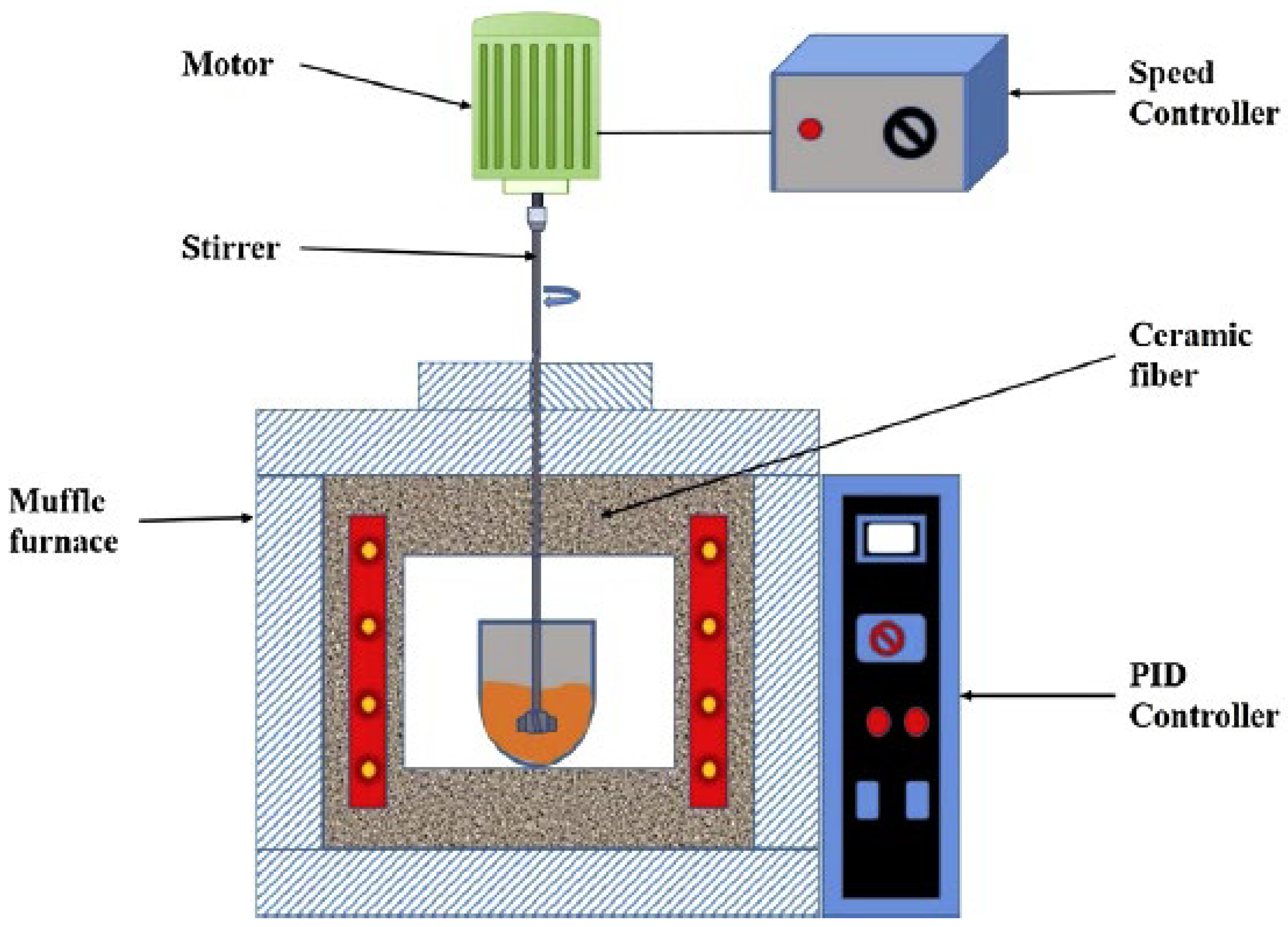
Liquid-state processing of Al nanocomposites/hybrids risks reinforcement settling due to density differences, mitigated by stir casting [123]. Conventional stir casting remains the most economically viable route for large-scale MMC production. Nanoparticles exhibit poor wettability and agglomeration during stirring, addressable via high-shear mixing coupled with reactive wetting [124,125,126,127]. Stir casting challenges include wettability enhancement, uniform dispersion, and porosity minimization. Advantages include scalability, cost efficiency, and capability for large-component fabrication [128].
Hot extrusion, a secondary processing technique, enhances AMMC properties by reducing porosity, thereby increasing ultimate tensile strength (UTS) and percentage elongation. Optimal UTS/elongation is achieved at 420 °C with an 18:1 extrusion ratio [129]. This process promotes homogeneous particulate dispersion, grain refinement, agglomerate fracture, and improved particle–matrix bonding. AMMC ductility depends on porosity, reinforcement distribution, and microstructure [130]. Research underscores the necessity to identify optimal manufacturing techniques for Al hybrid/nanocomposites [131], ensuring uniform reinforcement distribution (no clustering), improved wettability/bonding, grain refinement, non-reactive interfacial layers, suppressed grain growth, reduced processing temperatures, parameter optimization, higher reinforcement loading feasibility, enhanced mechanical properties, lower CTE, and cost efficiency [132,133].

5. Properties of Aluminum Matrix Nano Composites (AMNCs)

Reinforcement incorporation modifies aluminium alloy microstructures, enhancing mechanical properties like reduced density, increased strength, and improved stiffness [134,135]. Ceramic reinforcements (SiC, Al2O3) critically influence AMMCs’ tribological, thermo-mechanical, physicochemical, and mechanical characteristics. Nano-scale reinforcements further enhance properties: for CNTs,0.1 wt.% increases yield strength (YS) by 32% and ultimate tensile strength (UTS) by 8%, but reduces ductility by 16%. CNTs pin dislocations and hinder grain boundary migration under load, reducing elongation and increasing YS, consistent with dislocation strengthening mechanisms [136]. For MWCNTs, 0.75 vol.% with 1 h milling increases YS by 300% versus unreinforced material. Peak hardness (77 HV) occurs at 0.75 vol.% MWCNTs with 2 h milling. For SiC nanoparticles, enhanced matrix adhesion at elevated pressure/temperature forms Al4C3 and Si phases [137]. Adding 2 wt.% nano-SiC to A356 increases YS by 50% [138]. For nano-fly ash (FA), hardness increases from 75 HV (1 wt.%) to 114 HV (3 wt.%) [139]. The coefficient of thermal expansion (CTE) mismatch generates dislocations, strengthening the matrix [139]. Hardness improvement stems from dislocation pinning by nanoparticles [140]. Compressive strength rises from 289 MPa (0 wt.%) to 345 MPa (3 wt.%), attributed to void generation, particle-void interactions, load transfer, and grain refinement [141,142]. For graphene, 0.3 wt.% graphene nano-sheets increase tensile strength by 62% versus unreinforced aluminium [143].

5.1. Microstructural Characteristics of AMMCs

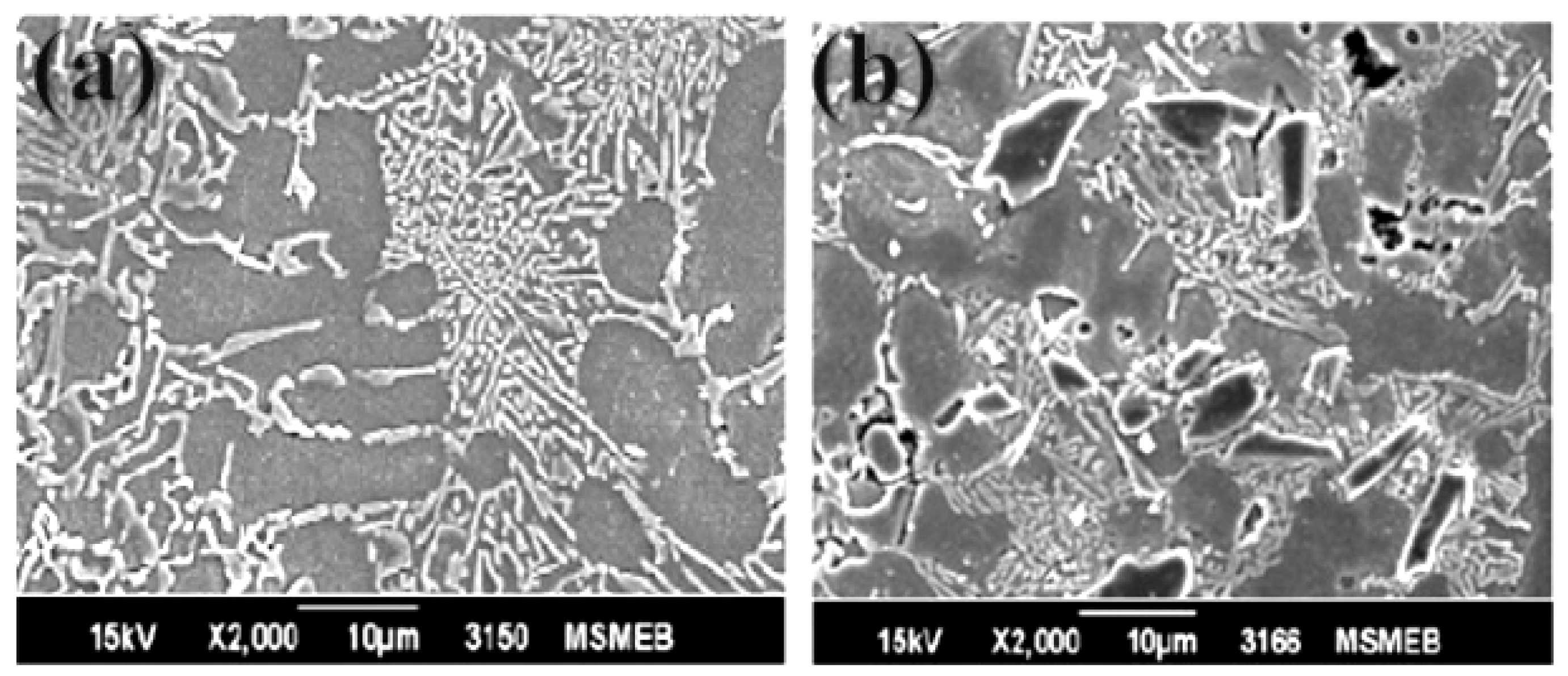
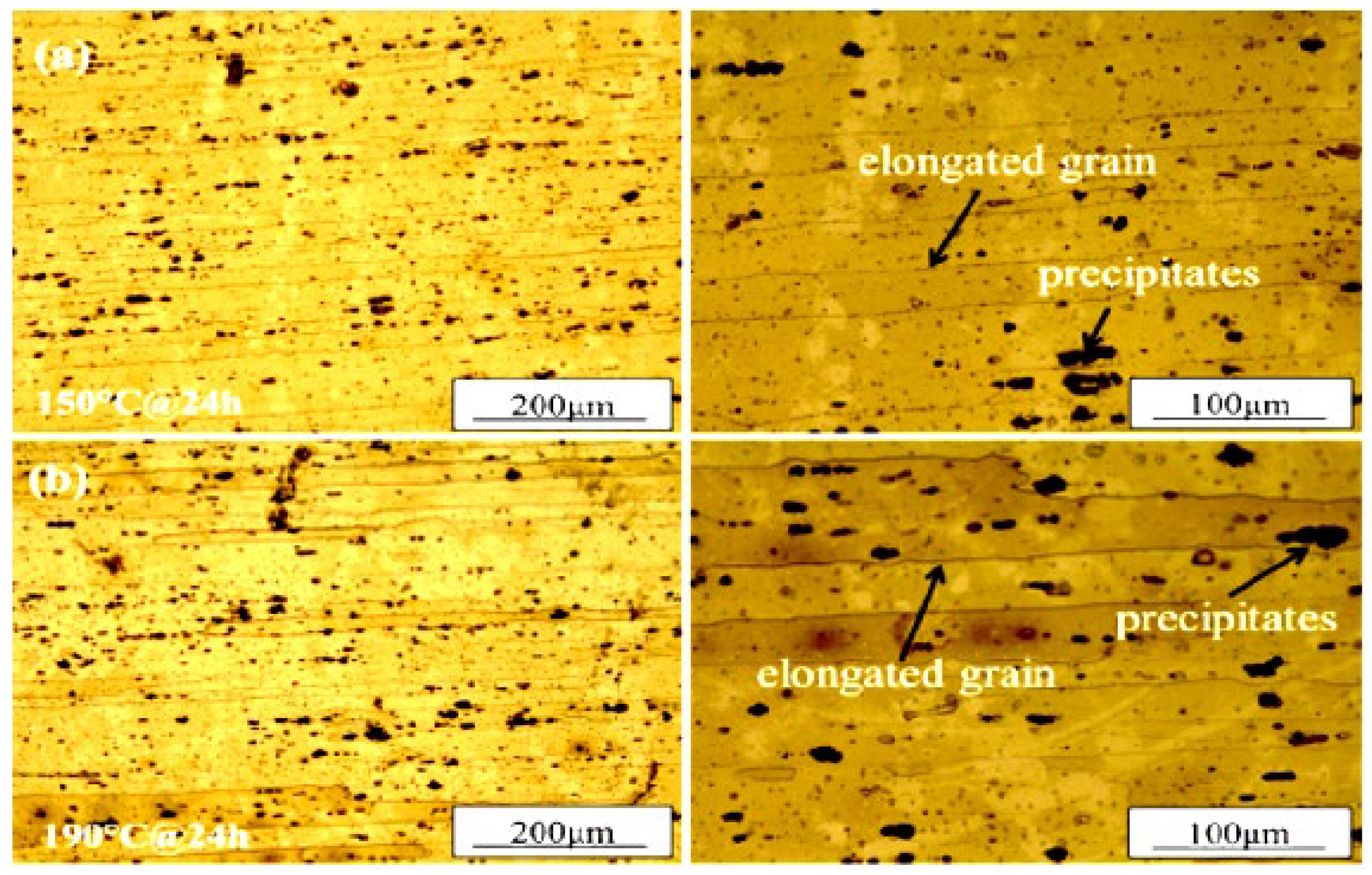
Microstructural analysis of stir-cast 11.8% Si-Al composites revealed a distinct interfacial zone adjacent to zircon sand (ZrSiO4) particles [144]. Magnesium and silicon segregation occurred at grain boundaries, with EPMA confirming ZrSiO4 presence. Disseminated zircon particles provided heterogeneous nucleation sites, refining eutectic silicon in both Si-Al alloy and composites (10–30 wt.% ZrSiO4). Eutectic silicon nucleation occurred proximal to ZrSiO4, while increased zircon content reduced pro-eutectic α-Al grain size. Pressure die casting with 60 wt.% ZrSiO4 (40–100 µm) achieved homogeneous particle distribution. Studies indicate zircon incorporation in Al–12% Si alloy enhances reinforcement dispersion and interfacial bonding [145]. Microstructural examination of 4.5 wt.% Cu-Al composites displayed a cellular structure with uniform ZrSiO4 dispersion (Figure 4 [146]) and intermetallic formation at reinforcement–matrix interfaces (Figure 4). Hypoeutectic dendritic structures with Zn-rich dendrites can be observed in Figure 5a,b and Figure 6 [146,147,148,149,150,151].
Aluminium hybrid composites incorporating alumina (Al2O3), zircon (ZrSiO4), silicon carbide (SiC), and graphite reinforcements exhibit enhanced hardness and superior abrasion/wear resistance [153]. ZrSiO4 achieves more homogeneous particle distribution and stronger interfacial bonding than Al2O3. Desired microstructures in 4.5 wt.% Cu-Al alloys are attainable with ZrSiO4 versus Al2O3 [154]. Al6061/ZrSiO4/graphite hybrids show primary α-Al dendrites with coarse needle-like Si particles [155]. Heat treatment refines alloy grain size, consistent with prior studies [156]. Adding SiC/ZrSiO4 to 4.5 wt.% Cu-Al forms secondary Al2Cu phases in inter-dendrites regions [157]. In LM13, ZrSiO4/SiC reinforcement yields fine globular eutectic Si near particles [158]. LM13 with fine/coarse ZrSiO4 achieves homogeneous dispersion, reducing porosity and clustering [159]. Optical micrographs (Figure 7a–d) reveal ZrSiO4-distributed eutectic Si with transformed morphology: acicular, denser globular morphology [146].
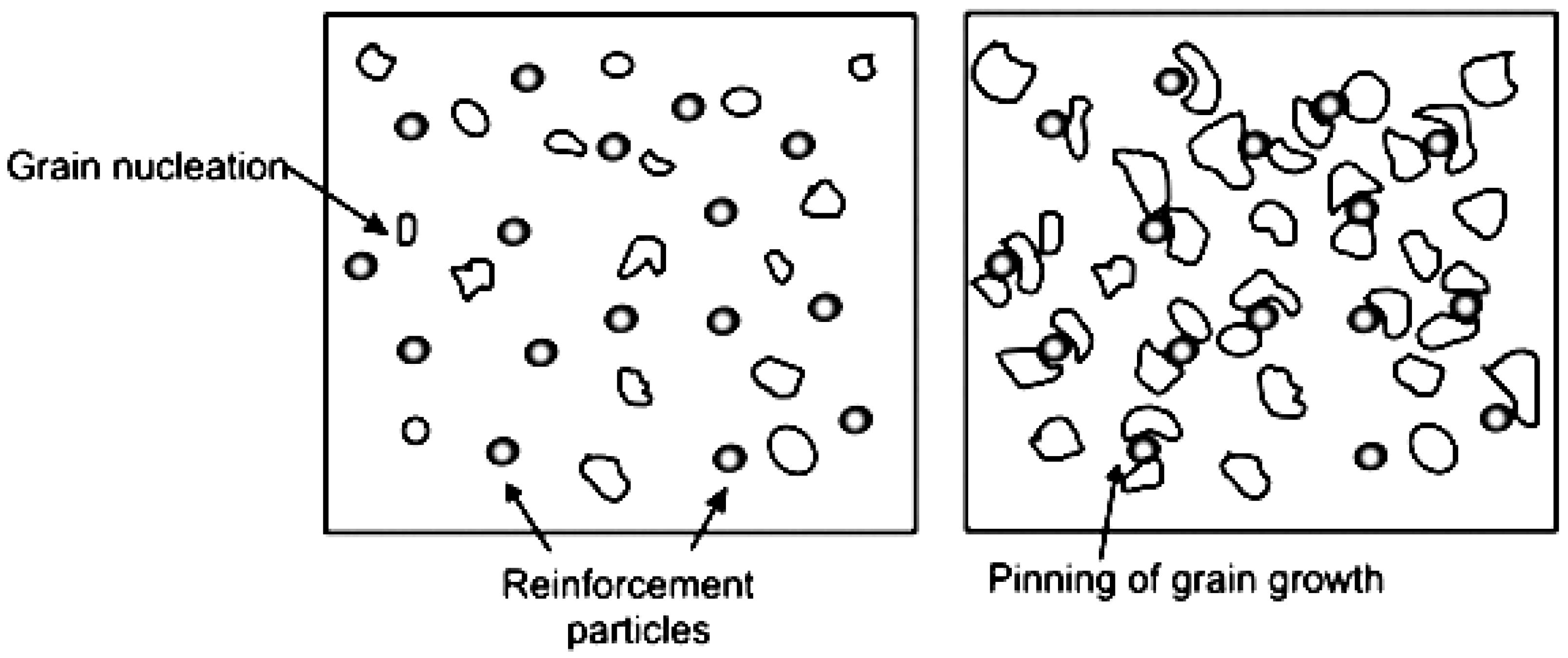
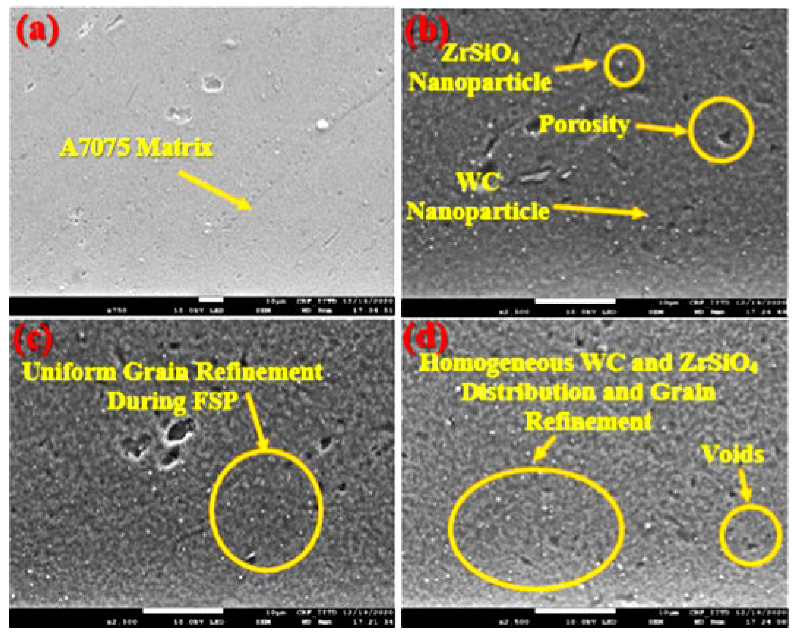
Figure 8a reveals agglomerated Al7075/ZrSiO4 composite at low integration. Mechanical stirring alone cannot disperse these clusters, necessitating pre-dispersion treatment. Al7075/ZrSiO4 composite powder at high mitigates agglomeration (Figure 8b), showing homogeneous nanoparticle distribution within the Al matrix. Repeated ball impacts fragment clusters, while mechanical bonding between Al2O3 and Al particles enhances wettability and dispersion [161]. Figure 9 shows Al/Al2O3 (0.5–1.5 wt.%) microstructures. Al2O3 addition reduces matrix grain size, with finer/higher-volume fractions inducing greater refinement via grain boundary pinning [160]. Figure 9a depicts as-cast Al6061 containing Fe-rich dendritic/non-dendritic phases (from milling contamination) and gas-entrapment micro porosity [162]. Increasing Al2O3 wt.% (0.5–1.5%) elevates nano composite porosity volume fraction. Extended stirring at higher speeds amplifies turbulence, promoting formation of grains peaks and distributions (Figure 10).
Figure 11 illustrates extruded Al6061 and nano-Al2O3 composites (0.5–1.5 wt.%). Extrusion refines grains, induces directional alignment, and reduces porosity [163]. Dynamic recrystallization occurs via new grain formation at prior boundaries (Figure 11a). Nanoparticles inhibit recrystallization by impeding grain boundary migration. Figure 11b–d reveals EDS after hot deformation, promoting dendritic transformation from non-dendritic structures. Residual micro porosity persists near these phases and boundaries [164]. Liquid-cast Al6061/Al2O3 nanocomposites (0.5–1.5 wt.%) exhibit uniform particle distribution with minimal agglomeration. Homogeneity depends critically on powder dispersion control, achieved via optimized stirring. During Al2O3/Al powder addition, Al powder dissolves, releasing nanoparticles; molten heat absorption cools the slurry; liquid-state stirring disrupts gas layers, enhancing wettability. Solidification involves particle–interface interactions: inert particles are either pushed or engulfed by advancing solid–liquid fronts. Consequently, Al2O3 nanoparticles migrate to grain boundaries and distribute within grains (Figure 12a–d).
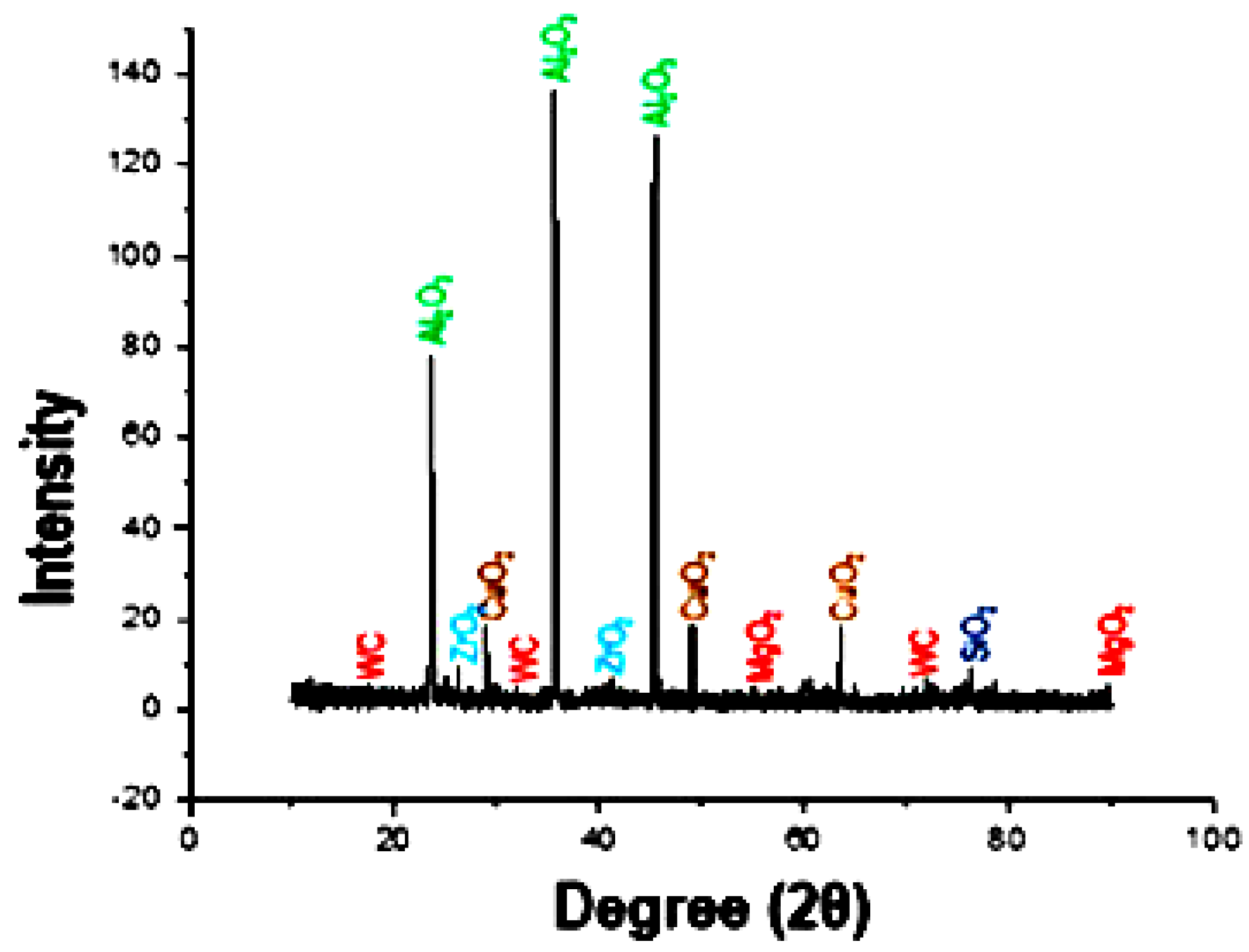
X-ray diffraction (XRD) analysis confirms the presence of oxide reinforcement within the aluminium matrix, as evidenced by characteristic diffraction peaks (Figure 13). Increasing carbide content correlates with progressive attenuation of primary aluminium peak intensities and concomitant amplification of oxide phase signatures. Notably, aluminium peaks in composite spectra exhibit systematic shifts toward lower 2θ values relative to unreinforced alloy diffraction patterns, indicating lattice strain induced by reinforcement incorporation [165]. Crucially, XRD confirms the absence of deleterious interfacial reaction products, demonstrating no chemical interaction between the Mg matrix and reinforcements particles under processing conditions.
This interfacial stability arises from thermodynamic inertness at fabrication temperatures, enabled by a protective titanium layer deposited on particle surfaces. The Ti coating functions as diffusion barrier, impeding atomic inter diffusion and suppressing reaction kinetics. Titanium’s high affinity for carbon forms stable TiC at the interface, further passivation the surface and preventing boron dissolution into the molten aluminium. This barrier mechanism effectively isolates from direct contact with the matrix, preserving reinforcement integrity and mitigating formation of brittle intermetallic phases that would compromise mechanical properties [166]. Consequently, the Ti interfacial engineering strategy ensures microstructural stability while maintaining clean, reaction-free interfaces essential for optimal load transfer in the composite system.
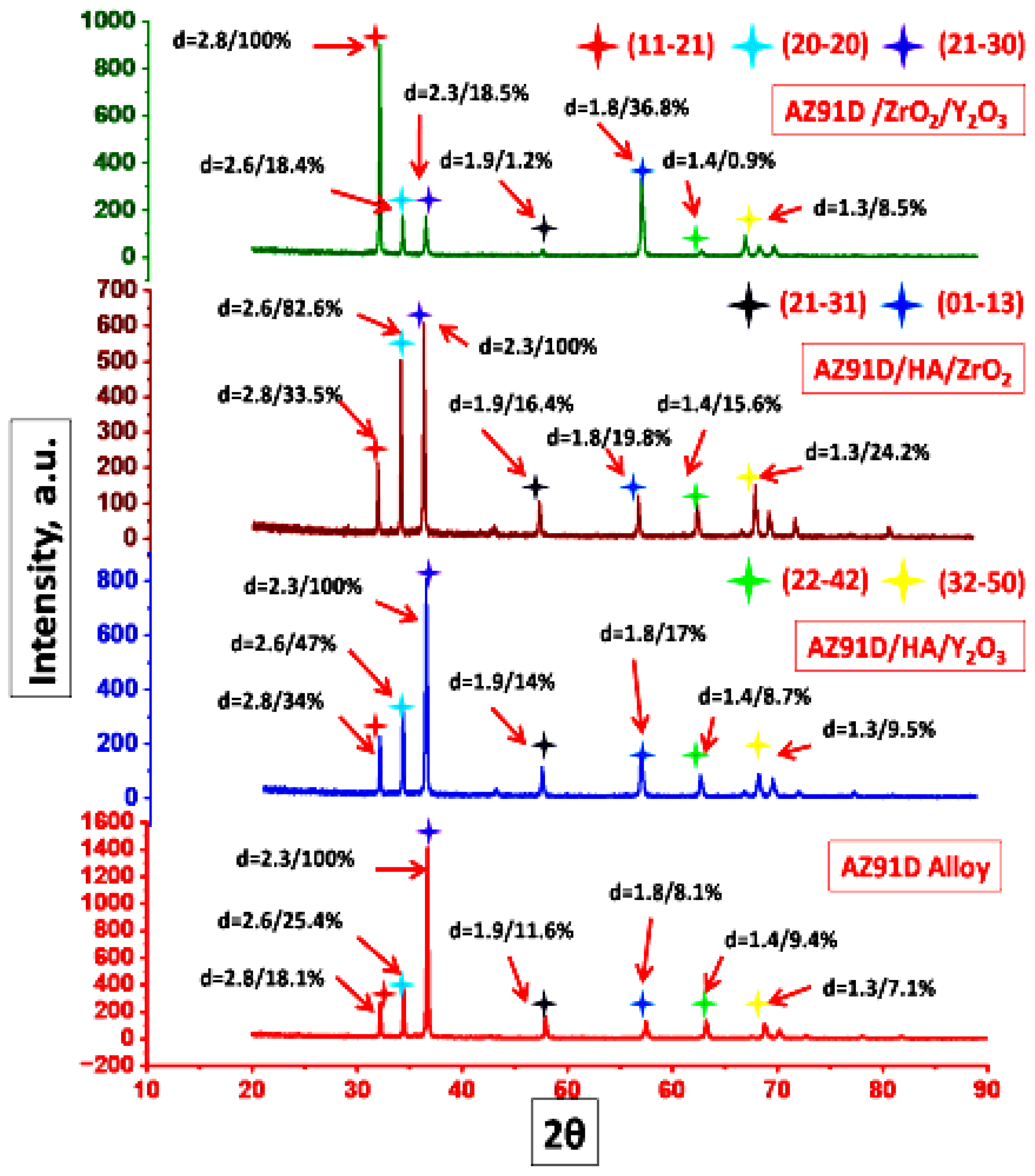
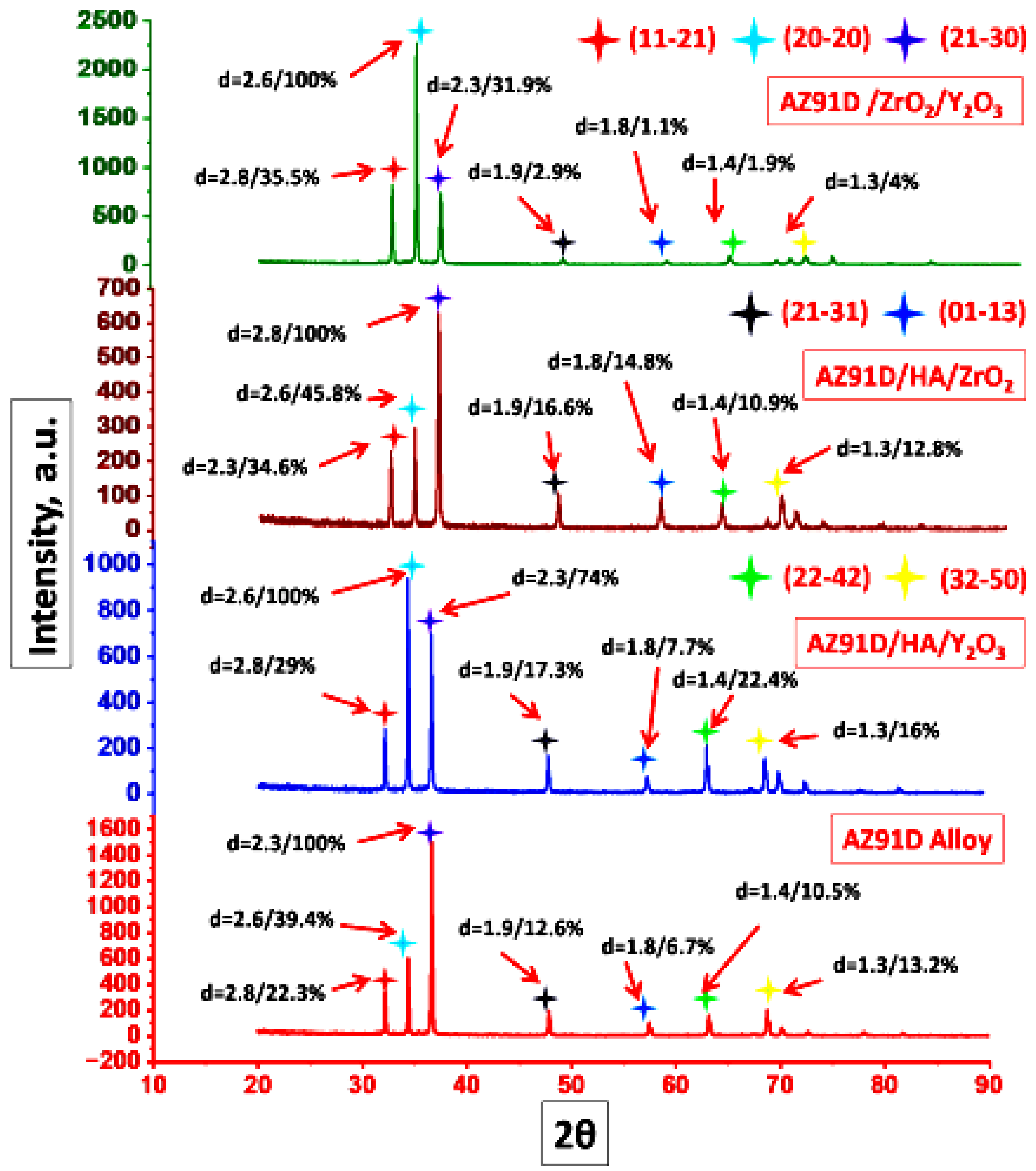
X-ray diffraction analysis of hybrid composites (Figure 14) demonstrates uniform dispersion of the AZ91D matrix, evidenced by prominent aluminium peaks at 38.4°, 44.71°, 65.1°, and 78.2° (2θ). The presence of a distinct SiO2 peak at 38.45° confirms silica reinforcement and contributes to enhanced mechanical properties. In composites, HA is identified by its characteristic peak at 36.2°. Crucially, the absence of discernible secondary peaks confirms no processing-induced contaminants or undesirable intermetallic phases within detection limits.
Alumina (Al2O3) and hematite (Fe2O3) phases remain undetectable despite potential trace presence, attributable to concentrations falling below the ~5 wt.% threshold for XRD phase identification sensitivity. This detection limit arises from XRD’s inherent intensity dependence on phase abundance and crystalline. The lack of observable oxide peaks implies either effective process control minimizing oxidation during fabrication or amorphous/nano crystalline oxide constituents whose diffuse scattering is obscured by the matrix signal. The clean diffraction patterns signify phase-pure composites with un-reacted reinforcement–matrix interfaces-a critical indicator of microstructural integrity. Peak positions and relative intensities further validate the absence of significant solid solution or lattice parameter distortions beyond expected thermal mismatch strains. This phase stability confirms the suitability of processing parameters for synthesizing contamination-free composites where reinforcement chemistry is preserved to optimize load transfer efficiency and interfacial cohesion under mechanical stress [167].

5.2. Microhardness and Density

Increasing reinforcement particle content elevates the interfacial surface area within the matrix, promoting progressive grain refinement through Zener pinning mechanisms that inhibit grain boundary migration during solidification and thermo-mechanical processing [168]. This augmented reinforcement–matrix interfacial area concurrently enhances resistance to dislocation motion under applied stress, elevating micro-hardness values proportionally to particle loading. The intrinsic hardness of ceramic phases further contributes to composite hardening by displacing ductile metallic constituents, thereby reducing plastic deformation capacity [169].
Densification behavior exhibits reinforcement-dependent trends. Incorporation of silicon carbide (SiC; ρ = 3.10 g/cm3) into Al6061 (ρ = 2.70 g/cm3) elevates composite density due to SiC’s higher specific gravity. Conversely, cenosphere (CSA) reinforcements (ρ = 1.65 g/cm3) reduce overall density. Quantitatively, Al6061-SiC composites demonstrate incremental density increases proportional to SiC mass fraction. In contrast, CSA-reinforced composites achieve a maximal density reduction of 6.58% at 10 wt.% CSA loading relative to unreinforced Al6061 [170,171,172]. This inverse density relationship stems from reinforcement particle architecture: a SiC-dense crystalline structure increases mass per unit volume; CSA-hollow aluminosilicate microspheres introduce porosity and lower effective density.
The density differential between the matrix and reinforcement (Δρ) fundamentally governs this behavior: positive Δρ (SiC > Al6061) increased density elevation; negative Δρ (CSA < Al6061) decreased density reduction. Hardness–density synergy must be optimized for target applications—high-specific-strength components prioritize CSA’s density advantage, while wear-resistant systems leverage SiC’s hardness contribution despite mass penalty. This reinforcement-selection paradigm underscores the critical interplay between compositional design, microstructural evolution, and resultant bulk properties in discontinuously reinforced aluminum matrix composites.
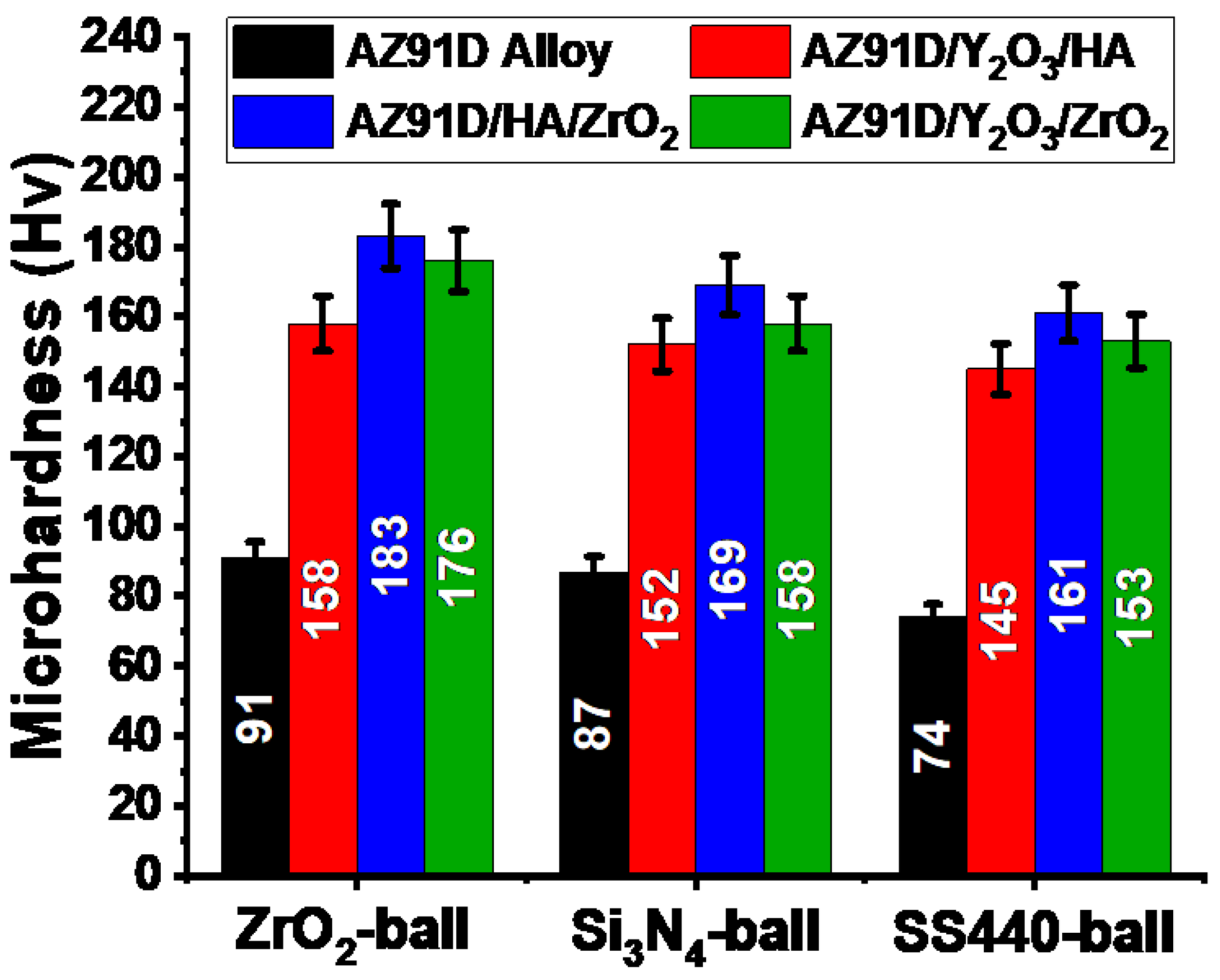
Figure 15 illustrates the Vickers hardness evolution of Al6061 and its hybrid composites. Incorporation of cenosphere (CSA) and silicon carbide (SiC) reinforcements significantly enhances composite hardness relative to the unreinforced matrix. A 10 wt.% SiC addition elevates Al6061 hardness by 37%, corroborating prior findings on SiC reinforcement efficacy. The non-monotonic hardness–CSA concentration relationship underscores a critical reinforcement threshold (~8–10 wt.% CSA) beyond which dispersion defects dominate. Optimal performance requires balancing the reinforcement fraction against process-induced agglomeration tendencies. Key contributing factors include viscosity effects, where higher CSA loading increases melt viscosity, impeding particle redistribution during stirring; inter particle forces, where Van der Waals attraction promotes clustering at elevated particle densities; solidification kinetics, where rapid cooling at high CSA content restricts diffusion-mediated particle dispersion. These results demonstrate that hybrid reinforcement strategies must optimize both constituent selection and processing parameters to maximize hardness while mitigating defect formation at critical reinforcement loadings [32].
The hybrid composites exhibit progressive hardening with CSA loading: hardness increases by 31.5% at 2 wt.% CSA and 46% at 8 wt.% CSA compared to monolithic Al6061. This strengthening arises from CSA’s intrinsic hardness, grain refinement via particle-induced nucleation, and dislocation generation from thermal expansion mismatch. However, a 5% hardness reduction occurs at 10 wt.% CSA. This anomaly is attributed to particle agglomeration during solidification processing. Agglomerates act as stress concentrators and reduce effective load-bearing cross-sections, diminishing overall composite integrity. Particle clustering also creates localized regions of matrix depletion, facilitating preferential deformation pathways. This phenomenon aligns with observations in SiC-fly-ash (FA)-reinforced Al6061 systems, where excessive reinforcement content similarly degraded mechanical properties due to compromised dispersion homogeneity [173].

5.3. Tensile Strength of AMMCs

Figure 16 illustrates the tensile strength evolution of Al7075 composites with reinforcement content. ZrSiO4 incorporation increases tensile strength by 18.26% versus unreinforced Al7075. Cenosphere (CSA) additions further enhance strength: Al6061-SiC composites exhibit tensile strength increments of 13.13%, 28.15%, 36.44%, and 47.31% at 2, 4, 6, and 8 wt.% CSA, respectively. This progressive strengthening correlates with homogeneous CSA dispersion and optimized matrix–reinforcement interfacial bonding, facilitating effective load transfer [174]. However, 10 wt.% CSA loading reduces tensile strength by 14.8% relative to the 8 wt.% CSA composite. This degradation stems from particle agglomeration and void formation at critical reinforcement loading, disrupting stress distribution and creating defect initiation sites.
The ductility were seen reduction with reinforcement addition. Elongation decreases incrementally with SiC incorporation and declines further with CSA addition. The Al6061-SiC-10% CSA hybrid exhibits maximal ductility loss (42.35% versus unreinforced alloy). This embrittlement arises from two mechanisms: constraint of plastic flow, where hard ceramic particles (SiC/CSA) act as barriers to dislocation motion, limiting matrix deformability; stress concentration, where particle–matrix interfaces and reinforcement clusters generate localized stress fields that promote premature void nucleation. The observed inverse relationship between strength and ductility aligns with established composite behavior reinforcements enhance stiffness and strength at the expense of elongation due to reduce crack tip plasticity. This trade-off is consistent with prior studies reporting similar ductility reductions in ceramic-reinforced aluminium systems. The facts demonstrate a critical reinforcement threshold (~8 wt.% CSA) for optimal property balance. Beyond this limit, processing-induced defects (agglomeration, porosity) dominate mechanical response, underscoring the necessity to optimize both composition and solidification parameters for target performance requirements [148].
The mechanical response of Al-TiC composites were increased with increasing reinforcement content. It is demonstrates increased specific strength with higher TiC weight percentages. This enhancement stems from titanium carbide’s capacity to impede dislocation motion and restrict plastic deformation through load transfer and Orowan strengthening mechanisms [175]. Conversely, as exhibits a progressive reduction in percentage elongation with TiC addition. The embrittlement correlates directly with reinforcement loading, as hard TiC particles act as stress concentrators promoting void nucleation; constrain matrix ductility by inhibiting dislocation mobility; reduce the effective cross-sectional area for plastic flow. The inverse relationship between strength and ductility follows established composite principles where ceramic reinforcements enhance stiffness at the expense of deformability. These trends confirm the characteristic strength–ductility trade-off in particle-reinforced metal matrix systems, consistent with dislocation-pinning phenomena and reduced crack tolerance with increasing ceramic phase fraction [176].

5.4. Fracture Analysis

It shows Al6061 alloy fracture morphology with uniformly distributed large dimples, confirming ductile failure. Al6061/fly ash (FA) composites exhibit reduced void dimensions versus unreinforced alloy, indicating quasi-ductile fracture at the micro-scale but macro-scale brittleness. FA particle addition promotes grain refinement, constraining void growth and reducing ductility. The Al6061/12 wt.% FA fracture surfaces: ductile shear bands confirm residual plasticity; intact FA particles within dimples demonstrate effective matrix–reinforcement interfacial bonding and particle cohesion during fracture. Minimal particle pull-out and interfacial de-bonding validate strong adhesion [177]. The transition from macroscopic ductile to brittle (composite) failure results from FA particles: restricting dislocation mobility; creating stress concentration; reducing matrix continuity, while micro-void coalescence retains localized ductile characteristics at fracture initiation sites [177].

5.5. Wear Behaviour of AMMCs

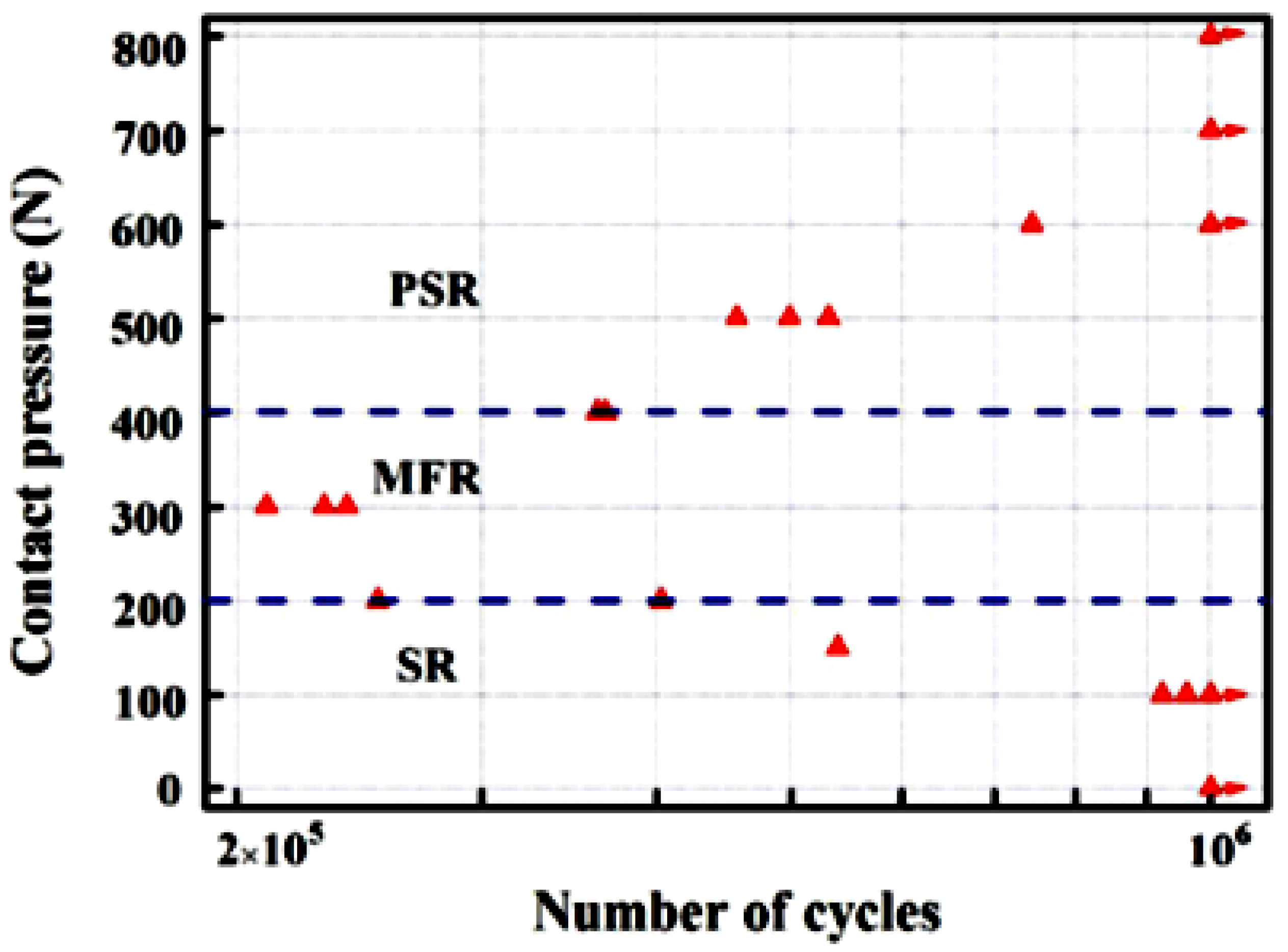
Figure 17a–c illustrates volumetric wear loss of ZrSiO4/Al7075 composites versus sliding distance at varying loads. Wear rate follows Archard’s law, primarily governed by applied load [178]. Composites exhibit lower wear rates than unreinforced alloy across all conditions [179]. Wear loss escalates with load for both materials, though composites maintain superior wear resistance. Three distinct wear regimes emerge under different loads [180]. At lower stresses, ZrSiO4 particles bear mechanical loads, enhancing composite wear resistance versus pure alloy. Figure 18a–c shows decreasing volumetric wear loss with rising SiC content. This reduction correlates directly with ZrSiO4-induced hardness enhancement, which improves abrasive resistance [181]. Ceramic reinforcement incorporation can increase wear resistance by ≤70% according to studies. A trade-off exists: coefficient of friction (COF) raises proportionally with reinforcement volume fraction due to increased surface asperity interactions [182].
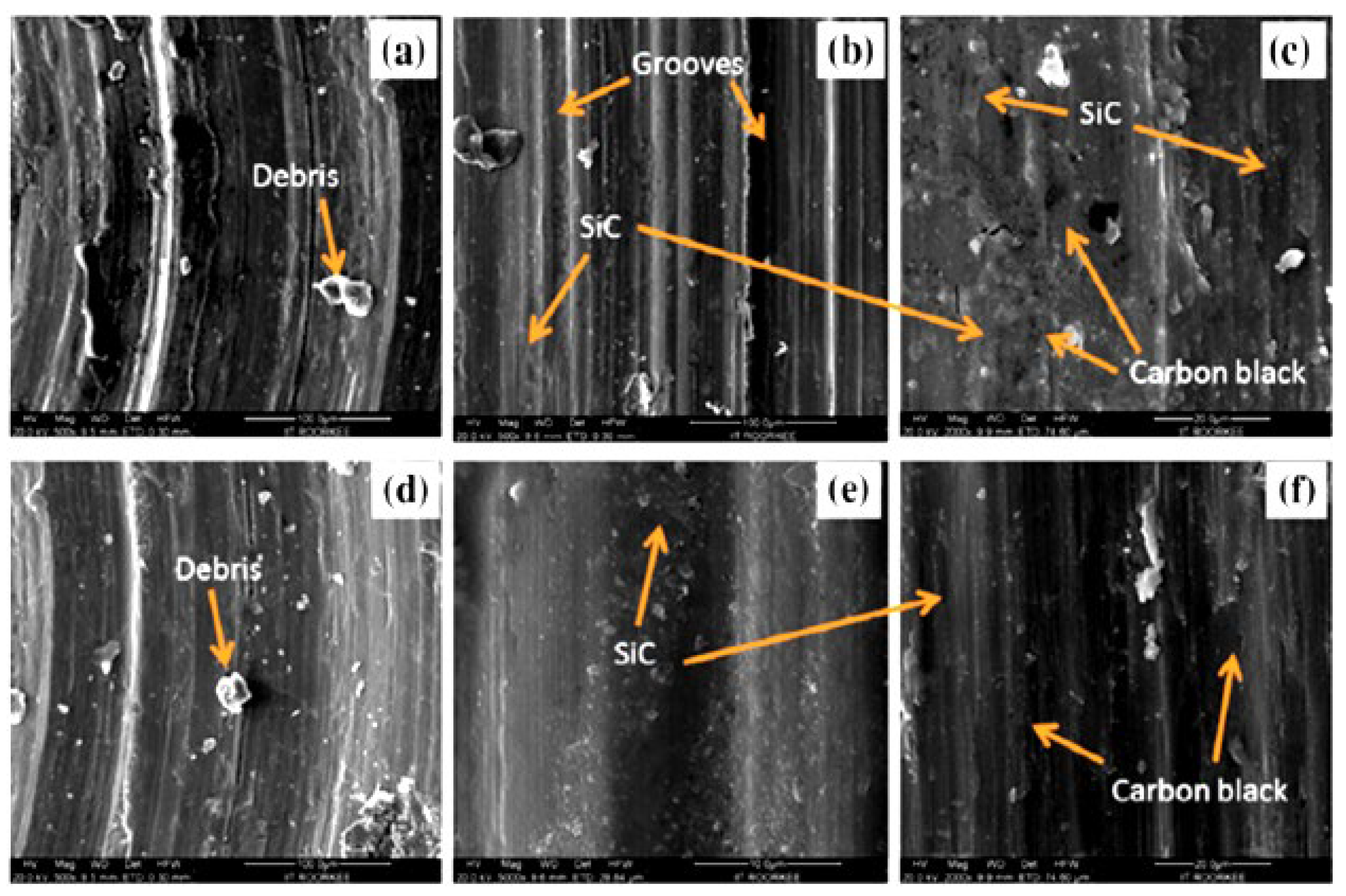
Figure 19a–c compares worn surfaces of ZrSiO4/Al7075 composites and unreinforced alloy after sliding wear testing. Wear mechanisms include adhesive and abrasive modes, confirmed by plastically sheared asperity debris [183]. ZrSiO4 reinforcement functions as supplementary abrasives, accelerating counterface wear. Generated debris acts as third-body abrasives, dislodging reinforcement particles. Minimal wear occurred in 15 wt.% ZrSiO4 composites at 60 N. Higher loads induced severe plastic deformation in low- ZrSiO4 composites, producing deeper grooves and elevated material loss [184]. This progression is evident in groove depth and density decrease with increasing ZrSiO4 content. Reduced grooving correlates with lower weight loss versus monolithic aluminium, demonstrating ZrSiO4’s role in enhancing surface integrity through matrix hardening and load support [185].

6. Properties of Aluminium Metal Matrix Hybrid Composites (AMMHCs)

Hybrid reinforcement in aluminum matrices offers significant design flexibility. Compared to single-reinforcement composites, hybrid systems demonstrate superior mechanical properties [186]. Incorporating SiC and graphite into Al matrix composites (AMMHCs) enhances both tribological and mechanical characteristics. Graphite provides lubrication, while SiC strengthens the composite; however, graphite diminishes overall mechanical properties and SiC reduces ductility. Heat treating Al/SiC-Gr composites at 630 °C were increased hardness via interfacial reactions forming Al4C3 [187]. SiC whisker reinforcement more effectively improves composite strength and elongation than particulate SiC. Enhanced mechanical properties arise from smaller SiC particles (≤10 µm). Further property improvements require hybrid reinforcement like SiC nanoparticles (SiCnp) + SiC whiskers (SiCw) [188]. Aluminum borate whiskers (ABOw, Al18B4O33) present a cost-effective alternative with high strength and stiffness. ABOw/Al composites are readily fabricated using conventional methods; applications include automotive shafts and brake rotors. Tungsten oxide (WO3), a hard alloy used for radiation shielding and functional materials [189], significantly increases composite yield strength (YS: 24.27 to 250 MPa), ultimate tensile strength (UTS: 47 to 287 MPa), and elastic modulus (69 to 96 GPa) when reinforcing Al. WO3/Al composites exhibit lower ductility than unreinforced aluminum but retain notably higher elongation than many composites. These excellent hybrid composite properties enable diverse applications [190].
Researchers calculated and compared the mechanical properties of ABOw-BaPbO3/Al hybrid composites with ABOw/Al composites. The hybrids were fabricated by forming a 100 µm thick reaction-synthesized BaPbO3 coating on ABOw surfaces. Hybrid composites exhibited superior properties versus ABOw/Al. Compared to pure Al and ABOw/Al, the ABOw-BaPbO3/Al hybrid showed significantly higher modulus of elasticity (104 GPa) and tensile strength (224 MPa). The Pb phase enhanced hybrid ductility [191]. Composites processed using a pulsed magnetic field achieved enhanced properties: UTS of 393.87 MPa and YS of 339.74 MPa. Hybrid reinforcement addition did not compromise elongation [192]. ABOw-SiC/Al6061 hybrid composites (5 vol.% ABOw, 15 vol.% SiC) were effectively fabricated via semi-solid stirring. Optimizing stirring temperature (630–680 °C) and time (20–30 min) increased tensile strength. UTS rose by 57.5% and 28.5% above base metal at 630 °C and 680 °C, respectively; elongation increased by 50% and 30.4%. Increasing stirring time from 20 min to 30 min elevated UTS from 214 MPa to 293 MPa and elongation from 2.5% to 4.6% [193]. Incorporating SiC particles (SiCps) improved the thermal expansion coefficient, wear resistance, and elastic modulus of SiC/Al2024 composites, while SiC whiskers (SiCws) increased strength and ductility. At 20 wt.% SiCw, increasing SiCp content (2 to 7 wt.%) enhanced elastic modulus and UTS but reduced elongation [194].

6.1. Microstructural Characterization of AMMHCs

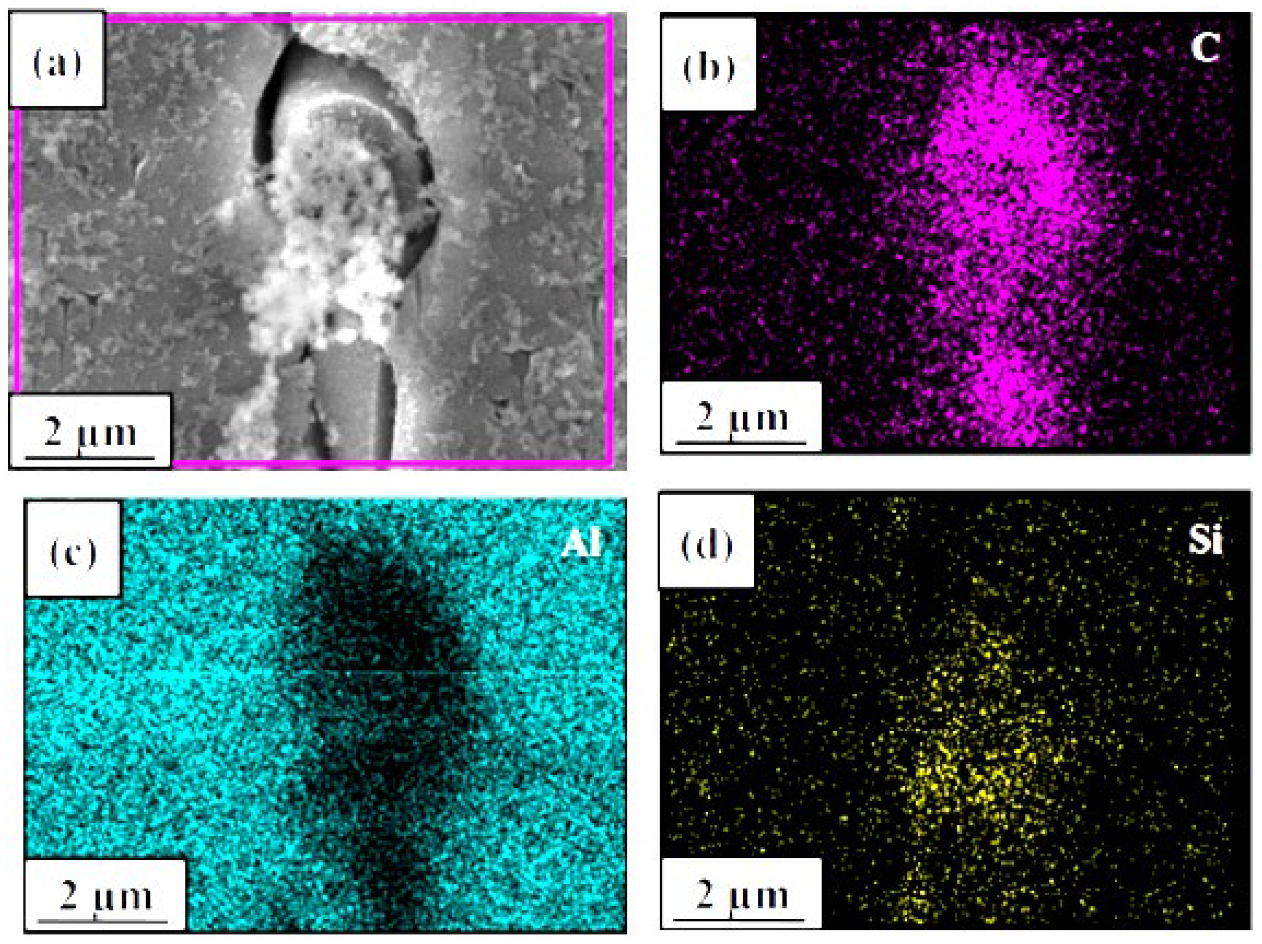
Figure 20 presents a TEM micrograph demonstrating a homogeneous spatial distribution of graphene particles within the analyzed sample. This uniform dispersion is critical for achieving consistent material properties. Complementary energy-dispersive X-ray spectroscopy (EDS) analysis, detailed in spectra, provides elemental confirmation of the microstructure. It exhibits distinct characteristic peaks corresponding to potassium (K), silicon (Si), aluminum (Al), oxygen (O), and carbon (C). The simultaneous presence of Si, Al, and O peaks strongly supports the formation of aluminum oxide (Al2O3) and silicon dioxide (SiO2) phases within the material. The detection of potassium (K) indicates the additional presence of potassium oxide (K2O or related compounds), further corroborated by the significant oxygen peak. Carbon (C) is commonly detected in EDS due to surface contamination or sample preparation (e.g., conductive coatings).
Quantitative assessment of the EDS profile identifies silicon and its associated oxygen as the predominant elemental constituents, confirming silica (SiO2) as the dominant phase. This silica originates directly from the calcined rice husk ash (RHA) precursor material used in the synthesis [195]. The homogeneity observed in the SEM image is thus validated by the consistent elemental signatures across the analyzed regions represented in the EDS spectra. The lack of significant elemental segregation or localized enrichment in the EDS maps confirms the effective integration and uniform distribution of the RHA-derived silica particles throughout the matrix. This uniform composite microstructure is essential for predictable mechanical and functional performance. The combined SEM/EDS analysis conclusively identifies the primary phase as SiO2, verifies the incorporation of Al2O3, and reveals the presence of potassium-containing oxide phases, all derived consistently from the RHA source [195]. The data confirm successful processing yielding a homogenously distributed silica-based composite material.

6.2. Tensile Test of AMMHCs

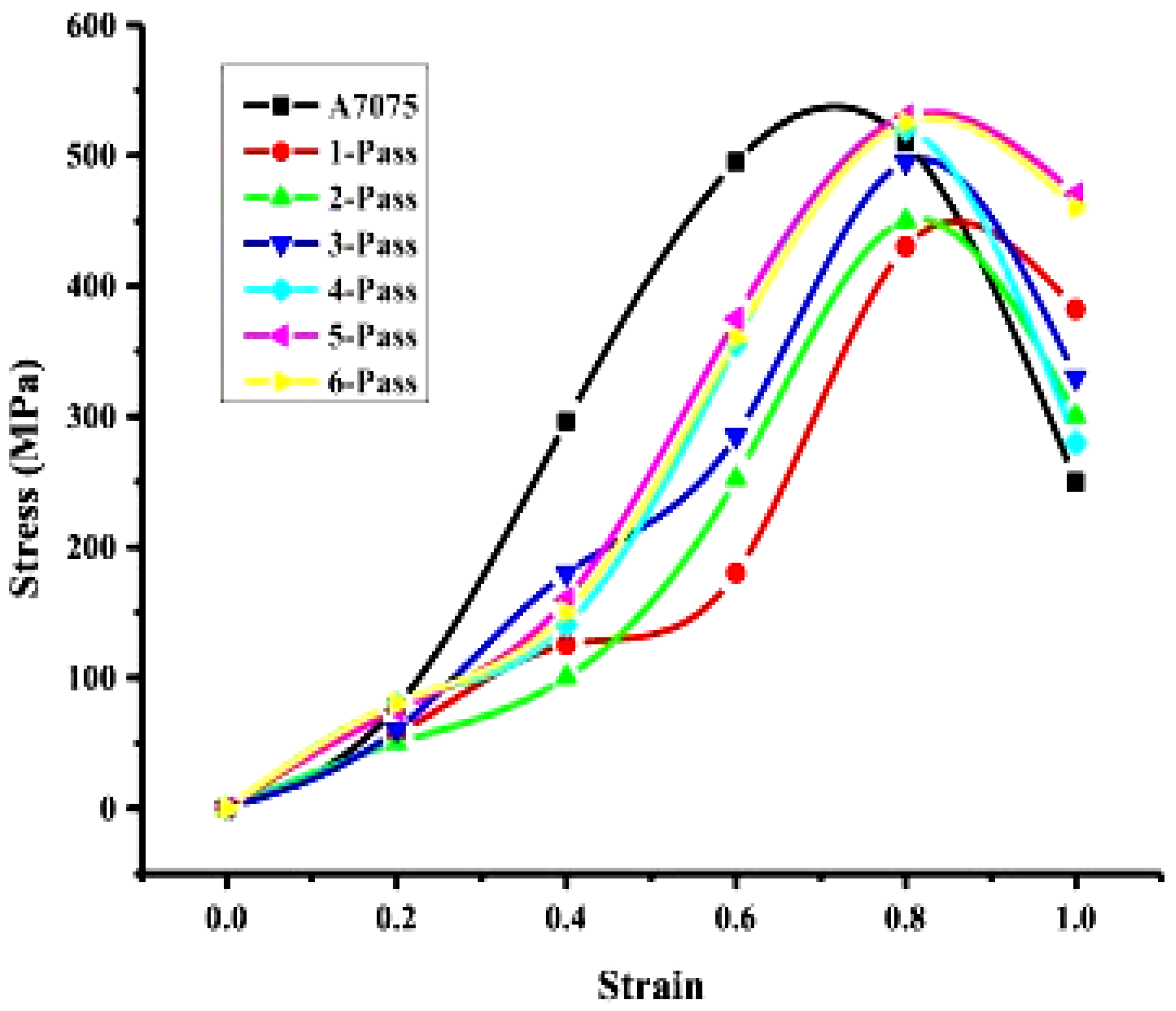
Tensile testing provides fundamental engineering properties essential for material selection and design validation, including modulus of elasticity (E), ultimate tensile strength (UTS), and yield strength (YS). These properties were experimentally determined for three hybrid composite variants (designated Specimen A, B, and C) following standardized procedures. Specimens were precision-machined according to relevant ASTM standards (typically ASTM E8/E8M for metallic materials) to ensure dimensional conformity and minimize gripping effects. Testing was performed under controlled displacement rates using a servo-hydraulic or electromechanical universal testing machine (UTM), equipped with calibrated load cells and an extensometer for accurate strain measurement. Figure 21 presents the characteristic stress–strain curves obtained from these tests, illustrating the mechanical response of each composite under uniaxial tension. The curves delineate the elastic deformation region (where stress is proportional to strain, defining E), the onset of plastic deformation (indicating YS, typically determined by the 0.2% offset method), and the ultimate tensile strength (UTS, the maximum stress sustained). Post-UTS behavior, including necking and fracture, is also evident.
Quantitative analysis revealed a progressive enhancement in strength across the specimen series. The average UTS values were measured for samples. This represents a measurable strength increment between composites. While the specific YS and E values are not explicitly detailed in this summary, these critical parameters are directly derivable from the stress–strain curve data (Figure 21). The YS defines the stress threshold for permanent deformation, crucial for structural applications. The E, calculated from the initial linear slope of the curve, quantifies the material’s inherent stiffness under load. These empirically determined properties (E, UTS, YS) are indispensable for assessing the composites’ suitability for specific engineering applications, predicting performance under service loads, and facilitating comparative analysis with alternative materials or processing conditions [196]. The systematic increase in UTS from Specimen A to C suggests a positive correlation between the specific hybrid reinforcement configuration or processing parameter represented by the specimen designation and the composite’s load-bearing capacity [197].
Fractographic analysis of tensile-tested hybrid composites is presented in Figure 22a–d. The unreinforced alloy fracture surface (Figure 22a) exhibits classic ductile failure morphology, characterized by large, deep dimples and significant voids resulting from extensive plastic deformation and micro voids coalescence. In contrast, composites incorporating graphite (Gr) and titanium carbide (TiC) reinforcements (Figure 22b–d) show distinct fracture features. The presence of Gr and TiC particles promotes the formation of notably smaller dimples. However, fracture toughness is compromised at 4 wt.% TiC due to particle clustering, acting as stress concentrators. Further increasing TiC content induces a transition towards brittle fracture mechanisms. These surfaces display prominent transgranular cleavage facets alongside coarse dimple features [198]. The degradation in toughness and shift in failure mode are directly attributed to the higher TiC concentration. Crucially, the uniform distribution of TiC particles throughout the aluminum matrix is essential for achieving effective reinforcement-matrix bonding. This homogeneity facilitates efficient load transfer and significantly enhances the composite’s overall mechanical properties [199]. The fractography thus directly correlates microstructural features (particle size, distribution, clustering) with the macroscopic mechanical behaviour and failure mechanisms.

6.3. Wear Behaviour of AMMHCs

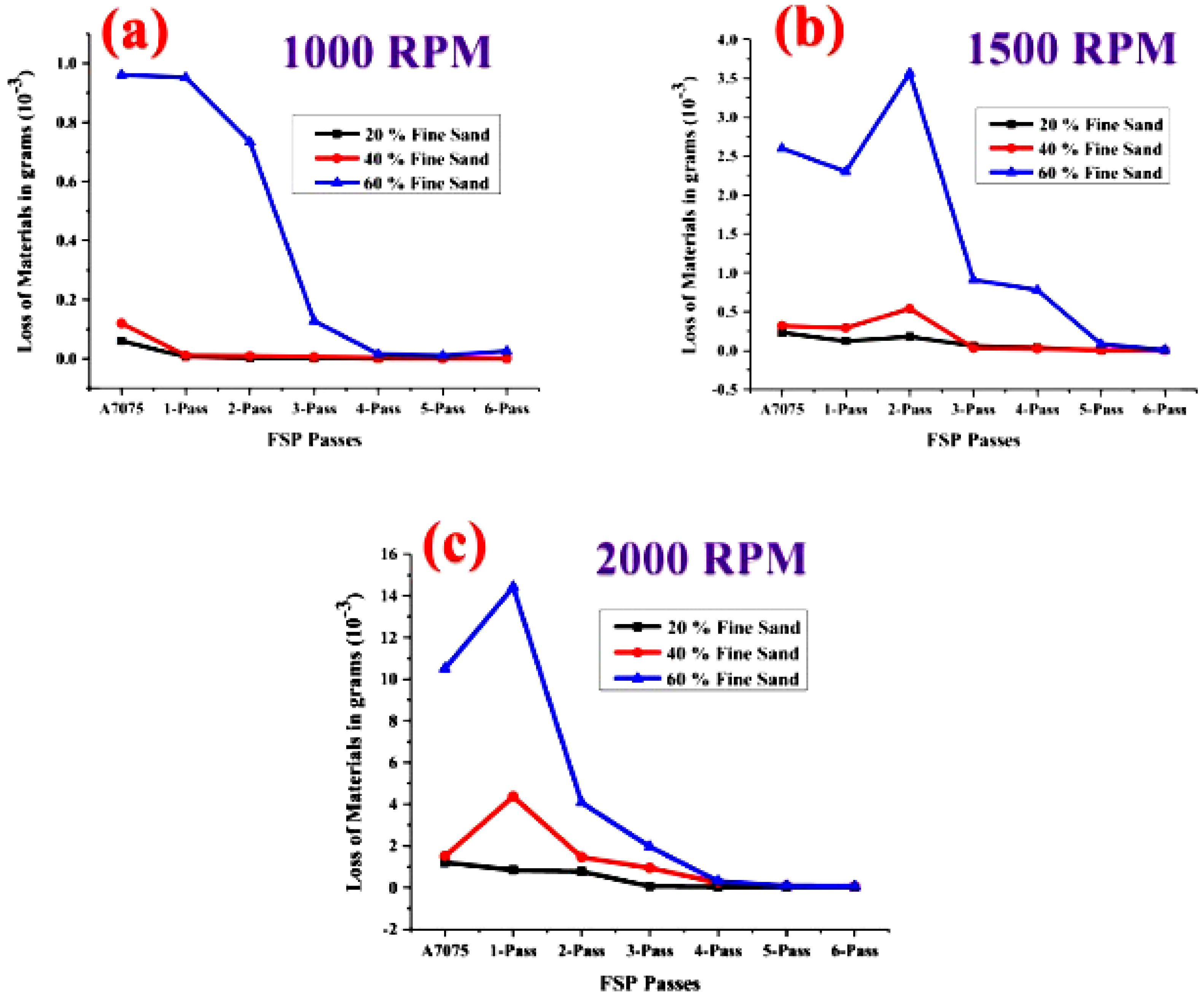
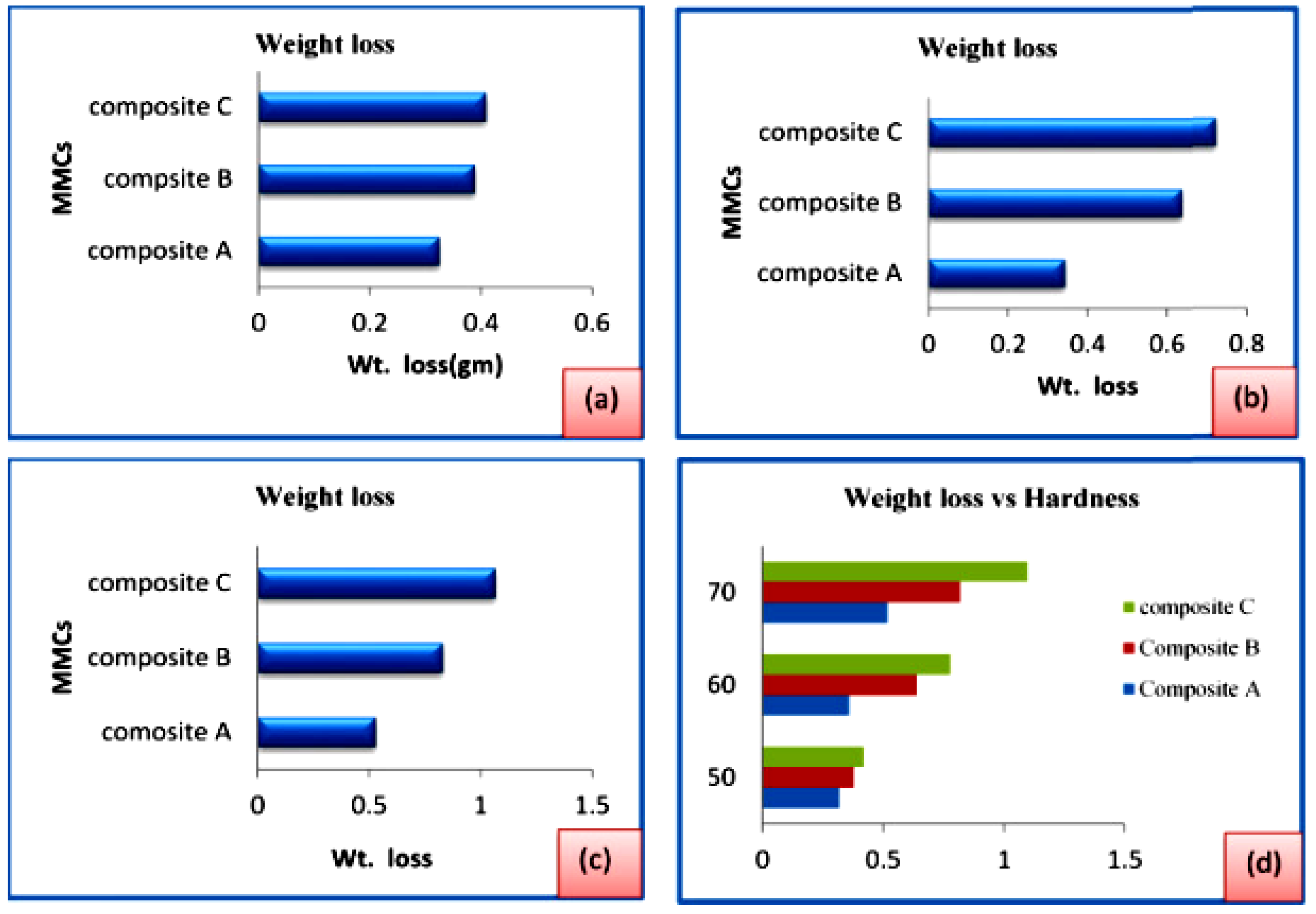
Figure 23a–d illustrates the weight loss behavior of Al7075 composites during wear testing under applied loads of 2.5 N. Analysis reveals a consistent inverse relationship between SiC reinforcement content and weight loss; increasing the SiC weight percentage (wt.%) significantly reduced material loss. This enhancement in wear resistance is attributed to the synergistic effect of silicon carbide (SiC) particles. The incorporation of SiC inherently improves composite toughness [200], providing a harder, more wear-resistant matrix. Simultaneously, during sliding contact, softer CSA particles are liberated and act as solid lubricants at the mating interface. This interposing layer effectively reduces direct metal-to-metal contact, lowering the coefficient of friction, which consequently diminishes wear loss. The data explicitly show a decrease in the friction coefficient with rising CSA wt.%.
The effect of applied load is also critical. Increasing the load from 10 N to 20 N intensified the contact pressure and interaction severity between the surfaces. This heightened interaction elevated the friction coefficient, leading to a corresponding increase in wear loss for all composite variants. However, under these higher loads, the composites still exhibited superior wear resistance compared to the unreinforced alloy. An important mechanism counteracting wear during loading is work hardening [201]. The plastic deformation induced at the subsurface layers hardens the material locally, thereby improving its resistance to further material removal [202].
The graphical data in Figure 23 demonstrate that the composite wear rate decreased substantially with CSA addition. Notably, the wear rates for composites containing 8 wt.% and 10 wt.% CSA were nearly identical. This plateau effect indicates that the primary wear reduction benefit is achieved with CSA additions up to approximately 8 wt.%. Beyond this threshold, the incremental improvement in wear resistance becomes marginal. The optimal wear performance thus results from the combined contributions of SiC-enhanced toughness, the lubricating action of CSA particles reducing interfacial friction, and the beneficial subsurface work hardening effect during sliding contact, with CSA content playing a decisive role up to its saturation point near 8 wt.%.

6.4. Morphology of AMMHC Worn Surfaces

Figure 24 presents scanning electron micrographs (SEMs) of worn surfaces for cast SiC/Al6061 composites. These images reveal characteristic adhesive wear mechanisms, evidenced by deep parallel grooves, material wedges, and delamination features aligned with the sliding direction [203]. In contrast, the unreinforced cast Al6061 alloy surface (Figure 24a) exhibits small pits accompanied by significant plastic flow. Comparative analysis of Figure 24b,c indicates substantially greater wear debris generation on both the Al6061 alloy and the SiC/Al6061 composite surfaces. Hybrid composites incorporating increased weight percentages (wt.%) of silicon carbide (SiC) display fewer surface flaws along the sliding path. This transition in morphology signifies a shift towards abrasive wear dominance as the primary material removal mechanism with higher SiC content [204].
The incorporation of coconut shell ash (CSA) and SiC particles demonstrably enhances composite wear resistance. This improvement is directly corroborated by the worn surface morphology, which shows a marked reduction in the extent of plastic deformation and material flow in the sliding direction [205]. The micrographs clearly illustrate that both SiC and CSA particles act as effective barriers, inhibiting the motion and detachment of surface matrix particles during sliding contact. This particle–matrix interaction restricts plastic deformation, minimizes subsurface crack propagation, and reduces delamination severity [152]. Consequently, the composites exhibit superior resistance to material loss. The presence of hard SiC particles increases surface hardness and load-bearing capacity, mitigating ploughing and grooving. Simultaneously, CSA particles may contribute to friction reduction and surface protection [206]. The synergistic effect of these reinforcements manifests as the observed reduction in adhesive and abrasive wear features, confirming the enhanced tribological performance of the hybrid composites [207].
Figure 25a–f present the worn surface morphology of Al-Mg-Si/BLA-Al2O3 hybrid composites, demonstrating the enhanced wear resistance achieved by incorporating both agro-waste by products (bagasse leaf ash, BLA) and ceramic material (Al2O3) compared to single-reinforced aluminum matrix composites (AMCs) [208]. Analysis reveals a significant shift in the dominant wear mechanism. Hybrid composites exhibit characteristics primarily associated with abrasive wear (micro-ploughing, scoring), contrasting with the adhesive wear (material transfer, severe plastic deformation, debris adhesion) often observed in single-reinforced systems. Critically, the hybrid surfaces show a marked reduction in adhered debris particles [209]. This reduction is mechanistically important; excessive debris adhesion on the composite surface significantly increases the coefficient of friction and accelerates wear rates through third-body abrasion and increased contact severity.
The micrographs directly correlate BLA content with debris accumulation. Surfaces containing 2 wt.% and 3 wt.% BLA (Figure 25a–c) exhibit substantially less adhered debris compared to the composite with 4 wt.% BLA (Figure 25d–f). This suggests that an optimal BLA concentration range exists below 4 wt.% for minimizing deleterious debris effects. The improvement in wear resistance stems from the synergistic action of the reinforcements. The hard Al2O3 particles enhance surface hardness and load-bearing capacity, reducing penetration depth during abrasive contact. Simultaneously, the BLA particulates, potentially acting as solid lubricants or modifying the matrix properties, help reduce friction and inhibit extensive material transfer/adhesion. The combined effect restricts plastic flow, minimizes subsurface crack nucleation, and lowers debris generation and adhesion. Consequently, hybrid composites with balanced BLA/Al2O3 content exhibit superior tribological performance by mitigating adhesive wear mechanisms and promoting a more controlled abrasive wear regime [210].

7. Fatigue Test and Fracture Analysis of AMMCs

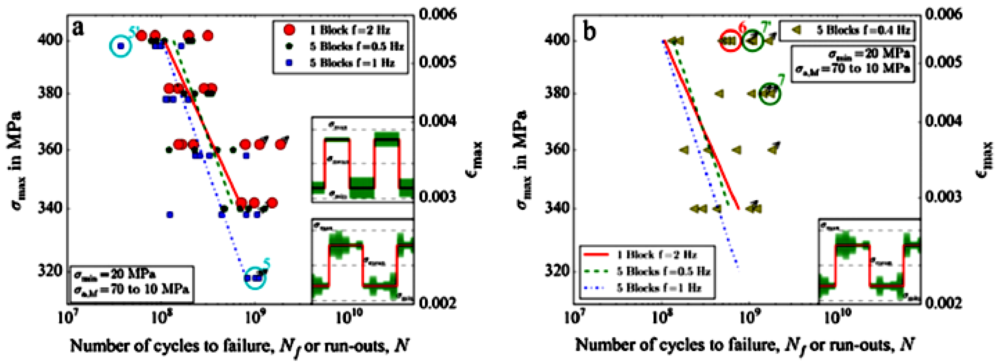
Figure 26 presents S-N curves from fatigue testing of unreinforced Al7075 composites. Specimens were cycled at endurance stresses of 125 MPa, 150 MPa, and 175 MPa. The high-stiffness ceramic reinforcements bear a significant portion of the applied cyclic load. Consequently, composites exhibit lower average strain per cycle under stress compared to the unreinforced matrix, enhancing fatigue resistance [211]. Ceramic particles significantly increase the endurance limit and fatigue life at a given stress level.
The hybrid composite achieved the highest fatigue life (Nf), surpassing composites reinforced solely with 10 wt.% or 20 wt.% TiB2. This superior performance stems from the synergistic action of the reinforcements. The hard TiB2 particles act as effective barriers to dislocation movement within the matrix during cyclic deformation. This hindrance reduces the mean slip distance and mitigates localized strain concentrations arising from dislocation pile-ups. Graphite (Gr) may further contribute by reducing interfacial friction or modifying crack initiation sites. The reduced slip length and localized strain impede fatigue crack initiation and early propagation, extending overall life. These results are consistent with established reinforcement mechanisms observed in discontinuously reinforced metal matrix composites [212]. The hybrid reinforcement thus provides a more effective barrier against fatigue damage accumulation than single-phase ceramic additions.
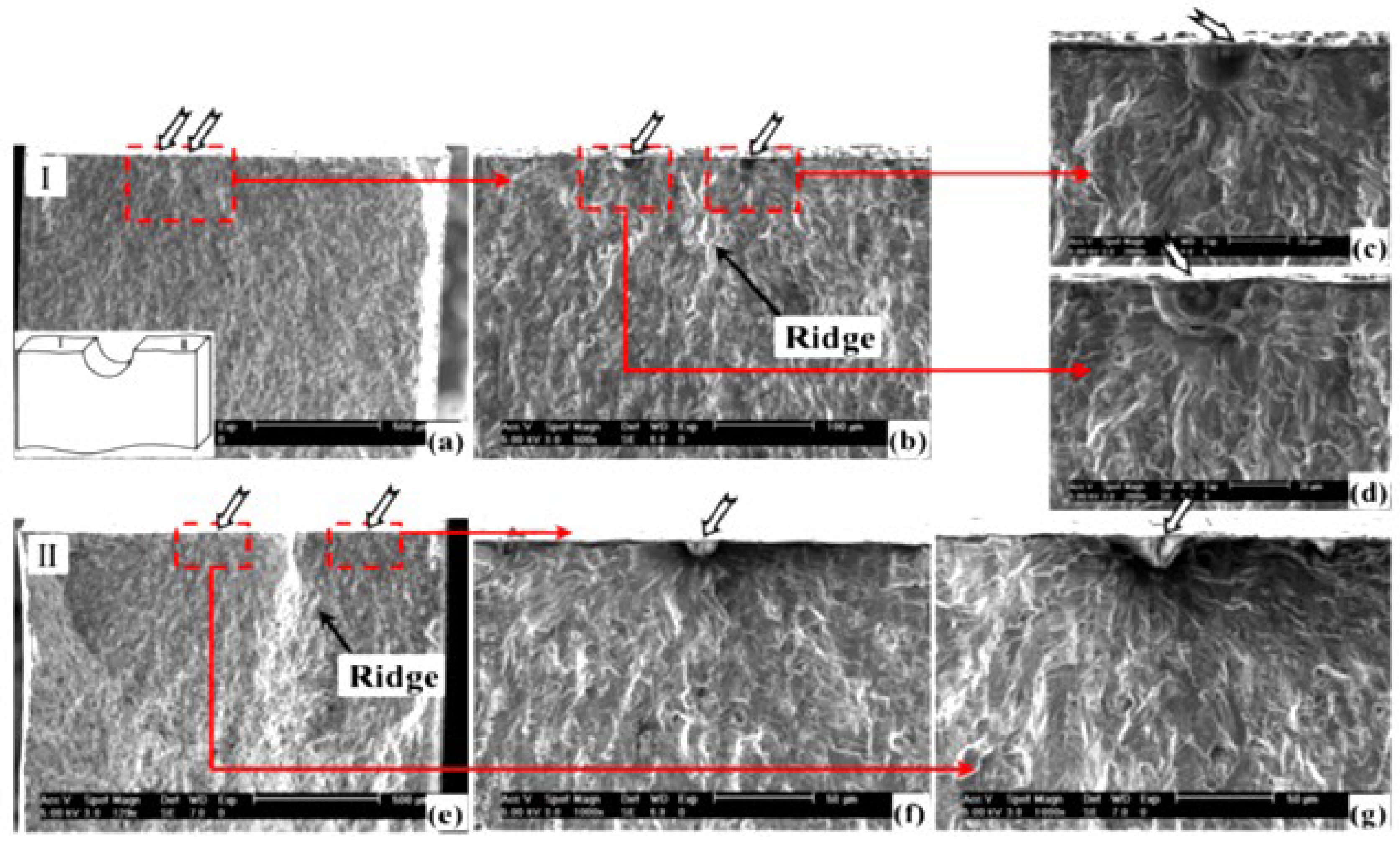
Figure 27A,B presents scanning electron micrographs (SEMs) of fatigue fracture surfaces for Aluminium composites tested at endurance stresses of 125 MPa, 150 MPa, and 175 MPa. Micrographs of unreinforced Al-alloy reveal characteristic delamination cracking, a mechanism contributing to its relatively low fatigue life. Analysis of reinforced composites shows evidence of cyclic deformation within the ceramic particles themselves under both high and low stress amplitudes prior to ultimate failure. Crucially, fracture in these composites occurred primarily within the nanoparticles or the aluminum matrix, rather than through widespread interfacial de-bonding or separation between the reinforcement and matrix. This indicates reasonably effective interfacial bonding [213].
In contrast, the hybrid composite exhibited a different failure mode. Despite the potential lubricating effect of graphite, its presence promoted interfacial weakness and delamination tendencies inherent to the Al-matrix [214]. Furthermore, agglomerated TiB2 particles acted as brittle stress concentrators. Under cyclic loading, minute cracks readily nucleated at these TiB2 clusters. The synergistic effect of matrix delamination and particle-induced crack initiation led to accelerated crack propagation. Consequently, the hybrid composite demonstrated lower fatigue resistance than both the 10 wt.% TiB2/Al6061 and 20 wt.% TiB2/Al6061 composites. The fractography thus demonstrates that while TiB2 particles undergo cyclic deformation and transgranular fracture or fracture within the matrix without catastrophic interfacial failure, the addition of graphite in this system exacerbates delamination and, combined with TiB2 agglomeration, creates preferential sites for fatigue crack initiation, ultimately reducing the composite’s fatigue performance under the tested conditions [215].
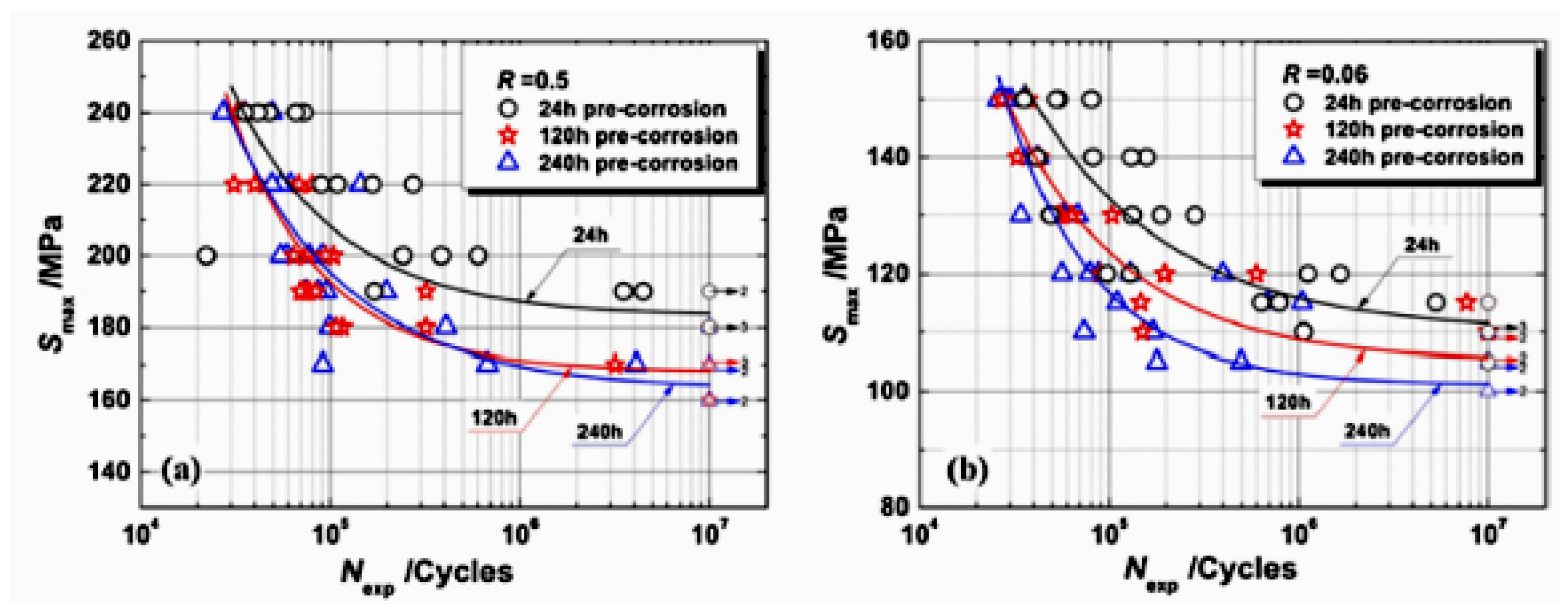
Fatigue behaviour is significantly influenced by specimen configuration (geometry and processing history) [216]. Figure 28a,b presents the push–pull fatigue test results for Al6061. The Basquin exponent (k), characterizing the stress–life relationship, is nearly identical for Al6061-T6 and rolled plate Al6061-T651 (0.119 vs. 0.130). This aligns with reported k-value variations within ~15% for different ferrous alloys [217]. Figure 29 depicts fracture surfaces for both specimens. Multidirectional crack propagation patterns are evident, indicating simultaneous crack initiation at multiple sites. However, shows no visible fatigue cracks externally; cracking initiated internally [218]. Consequently, significant crack formation onset differs markedly: ablation castings exhibit delayed crack initiation compared to conventional aluminum castings, where cracks initiated shortly after the first fatigue cycle [219].

7.1. High Cycle Fatigue Behaviour of AMMCs

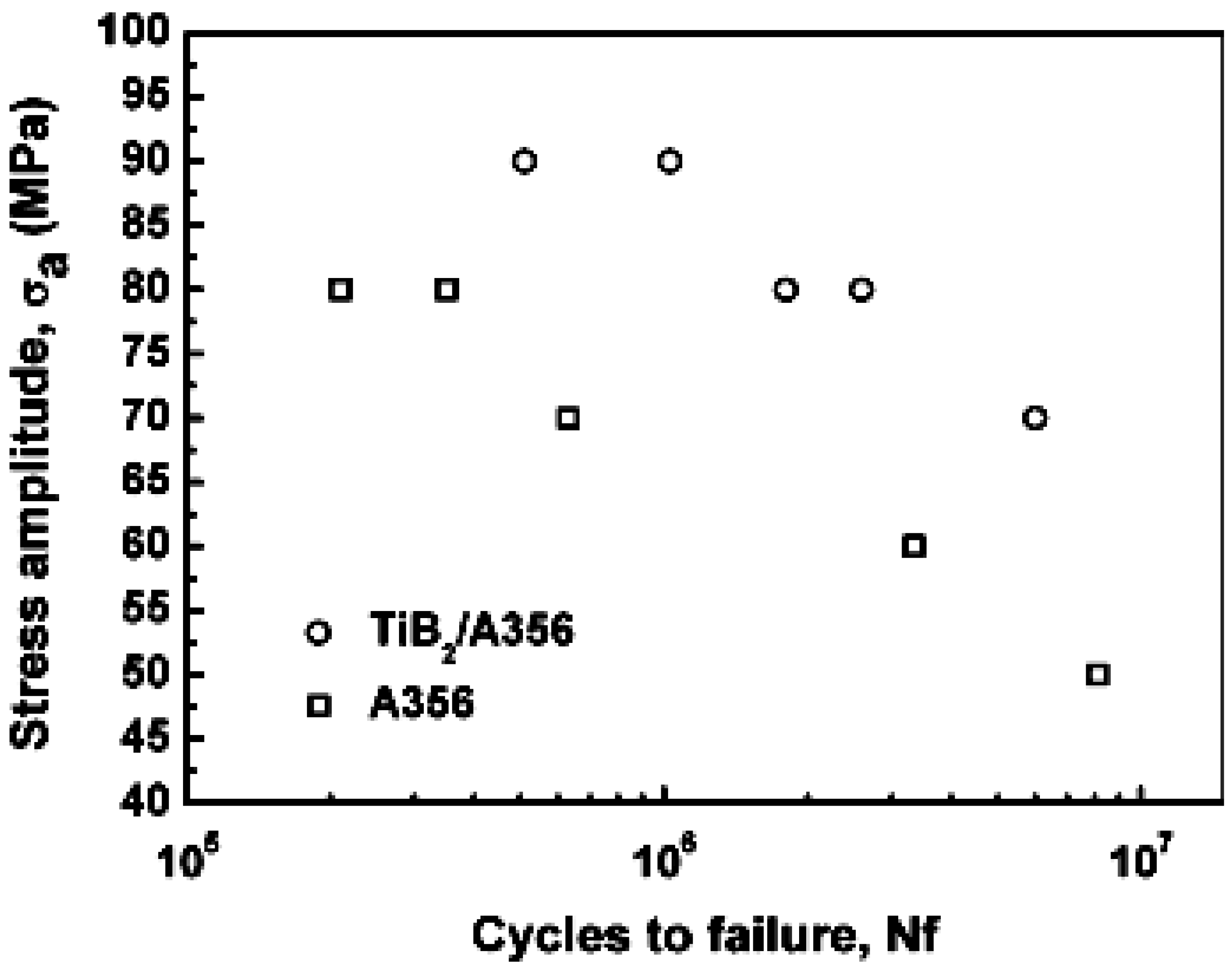
Figure 30 presents S-N curves depicting the high-cycle fatigue behavior of A356 alloy and TiB2/A356 composites. The composites exhibit significantly longer fatigue life than the unreinforced matrix. This enhancement primarily stems from the reinforcement particles impeding crack initiation. Their presence delays crack nucleation, extending the total fatigue life. Effective load transfer from the softer aluminum matrix to the stiffer TiB2 particles is critical; this redistribution lowers the local stress in the matrix [220]. The composite’s higher elastic modulus reduces total strain at any applied stress level, further improving fatigue resistance. Consequently, under identical stress amplitudes, composites experience lower cyclic strain than the unreinforced alloy. Conversely, crack initiation occurs via cyclic slip band formation. In situ-formed fine TiB2 carbide particles act as barriers to slip band progression, reducing the mean slip distance. This obstruction increases resistance to crack initiation [221]. The synergy of these mechanisms load transfer reducing matrix stress, modulus elevation limiting global strain, and particle barriers impeding localized slip collectively enhances the composite’s fatigue performance under high-cycle conditions.

7.2. Study of Crack Initiation Under Fatigue

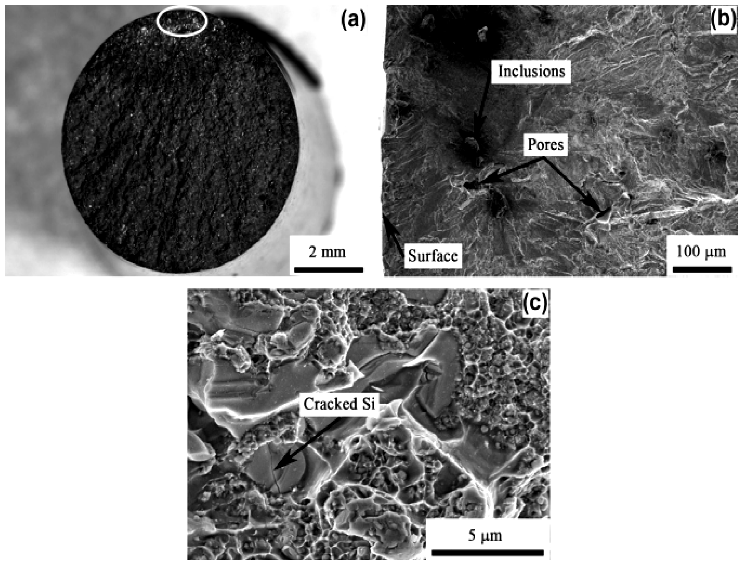
Figure 31 presents fatigue fractography of TiB2/A356 composites subjected to high-cycle fatigue testing. Mechanical characterization revealed significantly enhanced properties compared to unreinforced A356 alloy: ultimate tensile strength (UTS) of 382 MPa (+~42%), elastic modulus of 86 GPa (+~25%), and yield strength (YS) of 284 MPa (+~38%). Figure 31a identifies the primary crack initiation site (circled). Higher-magnification images (Figure 31b,c) detail the fracture morphology near this origin. Critical microstructural features influencing fatigue life were observed. Figure 31b reveals inherent casting defects, including subsurface pores and non-metallic inclusions. Energy-dispersive X-ray (EDX) spectroscopy confirmed these inclusions contain potassium (K), fluorine (F), chlorine (Cl), tellurium (Te), calcium (Ca), and sodium (Na)—residues from refining agents and modifiers used during processing [222]. These defects act as potent stress concentrators, particularly near the specimen surface where tri-axial stress states are less constrained than in the interior. Consequently, fatigue cracks preferentially nucleated at surface-connected or near-surface pores and inclusions, drastically reducing fatigue life [223]. This establishes casting defects (pores and inclusions) as primary initiators of premature fatigue failure.
Mitigation strategies align with previous research. Extrusion processing of similar in situAl2O3-TiB2/Al composites prior to fatigue testing effectively closed porosity and fragmented large inclusions [224]. This microstructural refinement yielded a demonstrable increase in fatigue life, underscoring the critical role of defect minimization. Notably, the TiB2 reinforcement particles themselves exhibited favourable behavior. Fatigue cracks propagated primarily through the aluminum matrix or along interfaces; no transgranular fracture within TiB2 particles was observed (Figure 31b,c). This resilience is attributed to the particles’ near-spherical morphology, fine scale, and homogeneous distribution, which minimize localized stress concentrations and provide limited sites for particle cracking [225]. However, alternative crack nucleation sites were identified. Figure 31c shows fractured eutectic silicon particles, whose inherent brittleness and angular morphology facilitate crack initiation under cyclic loading. This mechanism parallels observations in SiC-reinforced aluminum matrix composites (AMMCs), where large, irregularly shaped ceramic particles fracture readily under stress. Thus, while TiB2 reinforcement enhances bulk mechanical properties and intrinsically resists cracking, the composite’s fatigue performance is critically governed by extrinsic factors: the population density of casting defects (pores, inclusions) and the characteristics of secondary phases like eutectic Si. Optimizing processing to minimize defects and controlling eutectic microstructure are essential for maximizing fatigue life in these composites [225].

7.3. Growth Rate of Fatigue Crack

Figure 32 plots crack growth rate (da/dN) versus stress intensity factor range (ΔK) for Al composite and unreinforced Al alloy. The composite exhibits a higher da/dN across the entire ΔK range, indicating reduced resistance to crack propagation compared to the matrix alloy. This diminished crack growth resistance is attributed to the fracture or interfacial de-bonding of TiB2 reinforcement particles near the crack tip. These particle failures eliminate potential crack-bridging or deflection mechanisms, accelerating crack advance [226]. Consequently, the TiB2 particles in the TiB2/A356 composite contribute comparably to the increased crack propagation rate by fracturing or de-cohering under cyclic loading at the advancing crack front.

7.4. Crack Propagation Under Fatigue Failure

Figure 33 presents SEM micrographs contrasting fatigue crack propagation in unreinforced A356 alloy and TiB2/A356 composites. The unreinforced alloy (Figure 33a) exhibits characteristic fatigue striations. Conversely, the TiB2/A356 composite fracture surface (Figure 33b) displays significantly fewer striations and a coarser morphology dominated by tear ridges and dimples. The addition of TiB2 particles alters the failure mechanism, promoting void nucleation and coalescence under duplex slip conditions, suppressing striation formation.
Dimple analysis reveals distinct origins: large dimples correspond to fractured eutectic silicon particles, while finer dimples are associated with TiB2 particles. Notably, Figure 33b,c show intact TiB2 particles strongly bonded to the matrix, contrasting with fractured eutectic Si particles. Crack propagation preferentially occurs through the matrix alloy or along interfaces. Within the tested ΔK range, advancing cracks were unable to penetrate the fine-scale TiB2 particles due to their small size and strong interfacial bonding. Instead, cracks either deflected around these particles or were arrested by them. This crack-arrest behavior is characteristic of finely dispersed, well-bonded reinforcements. In contrast, larger reinforcement particles typically facilitate crack growth via interfacial de-bonding or particle fracture. The composite’s fracture topography thus reflects the critical role of reinforcement size and interfacial strength in dictating crack path and resistance [221].
Figure 34 shows the fractography of A356-TiB2 MMC and unreinforced metal alloy at the DK level nearing the fracture. Figure 34a,b show ductile fracture in unreinforced metal and brittle–ductile fractography in the A356-TiB2 composite. In comparison to intermediate fractures, the fracture surface of alloys and composites has a rougher surface at the DK level that is near broken. As a result of the increased DK generated by the process zone, eutectic Si particles begin cracking and deboning. Furthermore, it was discovered that the zone enlarged greatly as DK at the crack tip increased [227]. As the process zone expands, more particles are integrated, increasing the likelihood of particle breakage and deboning.
In fact, the small TiB2 particles in situ are still free of crack at increased DK level, as shown in Figure 34c. This behaviour is different in most composites for particles ex-situ dominated by particle fracture. In contrast, a few dimples are observed in the interior of composite where TiB2 is absent, as displayed in Figure 34c. This indicates that TiB2-reinforced particles are separated from the metal matrix with an increase in DK. In this work, we found that very fine particles did not break but deboned from the metal matrix to generate ductile dimples. The reason behind the separation of TiB2 particle is poor interfacial strength as compared to the stiffness strength of TiB2. It is evident that there is mismatch in strength between the TiB2 particle and matrix interface. Such a mismatch creates the stress concentration zone and deteriorates the strength. Due to this, the TiB2 interface is more prone to voids, which results in failure. As DK increases, the TiB2 in the process zone also increases. As a result of the greater separation of TiB2, several voids are produced. Such voids proliferate and connect together, accelerating the crack rate in A356-TiB2-based MMC. It can be deduced that cracks form mostly on the surface, either at pores or at inclusions, and preferentially at fractured eutectic Si particles. These cracks have a tendency to propagate, which causes deboning of TiB2 particles. Cracking and deboning of eutectic Si particles increase as DK increases. As a result, tiny TiB2 particles split and form voids. The voids formed by shattered Si and released TiB2 particles connect when the DK increases, causing the MMC to fracture [228].

8. Creep Behaviour of AMMCs

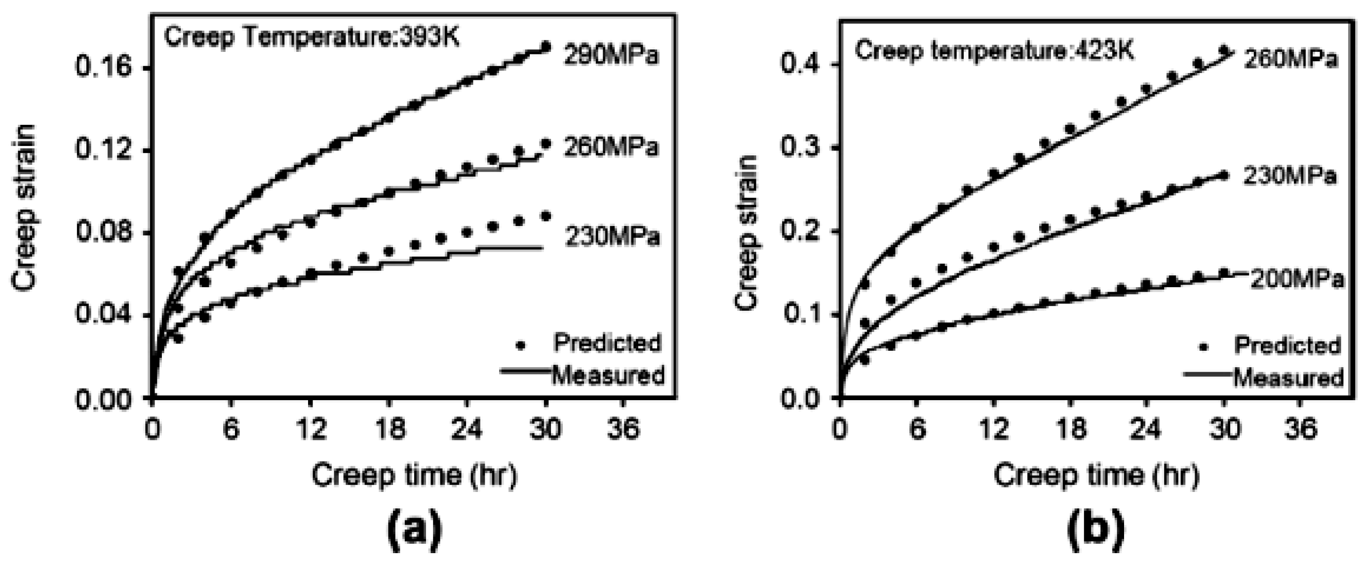
The primary objective of incorporating whiskers or particles into metal matrix composites (MMCs) is to achieve creep rates significantly lower than the unreinforced matrix. This enhanced creep resistance fundamentally relies on load transfer and dispersion strengthening mechanisms, where the reinforcement bears a substantial portion of the applied stress. Consequently, understanding load transfer dynamics, particularly with inhomogeneous reinforcements, is critical. The Shear Lag Theory is frequently employed to model this, assuming a perfect bond exists between the reinforcement (e.g., fibber, whisker) and the matrix, enabling full load transfer efficacy. This theory effectively describes stress distribution within MMCs at the initial loading state (t = 0) and during the secondary (steady-state) creep stage. A key finding [229] is that for moderate reinforcement levels, the magnitude of stress carried by the reinforcement is time-independent within the secondary creep regime. This implies the duration of load application does not alter the stress state under these conditions.
However, Element Modelling (FEM) reveals a more complex temporal evolution of stress within the reinforcement. As illustrated in Figure 35, FEM predicts a significant increase in the axial stress within a reinforcing fiber, rising from ~236 MPa at initial loading (t = 0) to ~526 MPa during the secondary creep stage. This demonstrates progressive stress redistribution over time: an increasing fraction of the total applied load is transferred to the reinforcement as the matrix creeps, while the composite’s overall load-bearing capacity inherently degrades under a sustained load. This rise in reinforcement axial stress is directly driven by the creep deformation of the surrounding matrix. Due to the assumed perfect interfacial bond, the creeping matrix imposes elastics trains on the reinforcement. The stiffer, typically non-creeping reinforcement (ceramic whisker) must then sustain higher stresses to accommodate the matrix’s time-dependent deformation, explaining the observed stress increase in Figure 35a–c.
Discrepancies between experimental and analytical creep predictions necessitated refinement of the analytical model using FEM insights (Figure 36a,b). The Figure plots creep strain rate against applied stress (60–130 MPa) for Al6061 and its composite (15 vol.% SiCp), considering varying interfacial de-bonding ratios (n = 0–1, where n = 0: fully bonded, n = 1: fully de-bonded). It quantifies the composite’s strain rate dependence on both stress level and de-bonding extent. This enhanced model provides accurate creep property approximation across a broad stress range and clarifies the relationship between ‘n’ and the stress magnitude at the matrix–reinforcement interface.
FEM analysis constrained the maximum plausible de-bonding ratio (‘n’) to ≤0.5. This contradicts prior assumptions predicting complete interfacial failure and fiber ineffectiveness at ‘n’ = 0.5 [230]. Figure 37a,b further depicts the axial stress within the matrix near the fiber end (Zone A) under 80 MPa applied stress for different ‘n’ values. Notably, axial stress becomes compressive at ‘n’ = 0.5. Reconciliation with experimental data confirmed the critical importance of three factors in accurately modeling MMC creep deformation: the proposed analytical modifications, precise geometrical meshing of the composite microstructure, and implementation of an appropriate exponential creep constitutive law for the matrix.
The final optimized analytical model demonstrated excellent agreement with experimental creep results, validating the refined approach and the identified interfacial de-bonding limits [231].
Figure 38a,b presents the life-time analysis of precipitation evolution in an Al-alloy composite during creep at varying parameter. The images depict distinct stages: as-crept. Similarly, The diffraction pattern, with cross-marking and dashed lines, confirms the concurrent presence of metastable θ’ (Al2Cu) and S’ (Al2CuMg) strengthening phases. Initial micro-creep shows nascent precipitation. After 160 h, significant secondary precipitation is evident within the matrix, reducing inter-precipitate spacing. Prolonged exposure to 300h induces coarsening: precipitate size increases while number density decreases, indicative of Ostwald ripening [232]. Interfacial analysis reveals strong SiC–matrix bonding at reference conditions (100 MPa, 60 °C). However, dislocation-mediated nucleation at the particle–matrix interface is highly non-uniform, exceeding nucleation rates in the matrix interior [233]. SiC particles impede dislocation glide during micro-creep, leading to pile-ups that locally promote heterogeneous nucleation, as marked by red arrows.
Specifically examine the load effects on precipitation after 300 h at 60 °C. Reducing the applied load enhances secondary phase nucleation density. Conversely, higher loads accelerate precipitate growth kinetics, favouring expansion and lengthening of existing phases. This demonstrates clear load dependence: elevated stress drives precipitate coarsening at the expense of nucleation density, while lower stresses promote a finer, denser precipitate distribution [234,235,236,237]. The observed micro-creep mechanisms including dislocation pinning by SiC, load-dependent nucleation/growth balance, and interfacial precipitation heterogeneity align closely with experimental findings under low-stress conditions [238,239]. The TEM evidence confirms the critical role of reinforcement particles in modifying local deformation and precipitation dynamics during creep [240].

Creep Failure Mechanisms of AMMCs

To understand the failure mechanism, two composite samples are taken for study at 15 MPa and 70 MPa, respectively, as shown in Figure 39a,b. Unbroken Al2O3 particles are noticed in the dimples of fracture surface of both samples [241]. Broken alumina particles were rarely found for various different loads. This proves that MMCs fails due to interface cohesion between the matrix and particle [242]. Absence of matrix in spinal of crystals also emphasizes the conclusion. The fractures in Figure 39a,b are mostly formed due to dimples created from coalescence and growth of void while matrix cleaving is not noticed, suggesting failure due to ductility [243,244,245,246,247]. By juxtaposing the fracture location of unreinforced metal alloy and reinforced metal sample shown in Figure 39a, it can be seen that the intensity of brittle fracture is higher in composites compared to unreinforced metal alloy. This is confirmed by the higher necking effect in the unreinforced metal alloy, which causes significant tertiary creep [248]. The difference in the size of dimples is noticeable in Figure 39b and is caused by low and high stress. There are larger dimples in the sample under 15 MPa than the sample under 70 MPa. This might be because of the crack process: at high stress, the formation of voids at the particle edge, which may result in the formation of dimples and fractures, may occur as a consequence of dimple coalescence at each particle. At low stress, the existence of many particles at each dimple and at larger dimples, following the initiation of cracks and fractures, is because of the dimple formation initiated from void coalescence produced at adjacent particles [249]. SEM studies undertaken for both samples along longitudinal sections are in sync with previous explanations. In Figure 40a–g, big cracks connected to many particles were noticed along the vertical axis (tensile axis). Individual voids generated over particles were barely noticed and not a single crack was found in the vicinity (about 500 mm) from the fracture surface. In Figure 40d,e,g, high stress samples showed different behaviours in which voids were formed at the edges of Al2O3 particles acting as crack initiators. Individual voids were observed in high concentrations in the vicinity (about 1 mm) from the fracture surface. The creep rate is always at its minimum for an unreinforced metal matrix compared to a composite. Propagation of crack under high stress results in the formation of one dimple for each particle, whereas under small stress, it needs the void coalescence between many particles prior to fracture, lengthening the tertiary stage duration [250,251,252,253,254,255,256]. The necking effect of the composite is very restricted in comparison to unreinforced samples [257].

9. Applications and Challenges of AMMCs

Aluminum matrix composites (AMCs) exhibit significant potential due to their tailorable properties and multi functionality. Strategic selection of micro- and nano-scale reinforcements enables precise engineering of specific characteristics. AMCs demonstrate superior wear resistance, making them highly suitable for demanding automotive components including brake rotors, pistons, cylinder liners, and bearings. Energy efficiency favors lightweight materials; AMCs offer an attractive strength-to-weight ratio, positioning them as critical materials for aerospace and automotive applications where weight reduction is paramount [258].
Despite these advantages, several challenges impede broader implementation. Key limitations include insufficient design databases, inadequate predictive models for property behavior (particularly elevated-temperature performance of aluminum alloys), and the high cost associated with many fabrication routes. Enhancing fracture toughness remains essential to improve damage tolerance in structural applications. Furthermore, significant property variations exist between AMCs produced via different casting methods, complicating process selection for specific engineering requirements.
Stir casting remains the predominant commercial manufacturing technique due to its cost-effectiveness and scalability. However, this method faces inherent limitations: (1) density-driven segregation—significant density differences between molten aluminum and common ceramic reinforcements (e.g., soft and hard) promote particle settling or floating, leading to inhomogeneous distribution. (2) Defect formation—entrapped gases and shrinkage during solidification cause porosity. Poor wettability between molten metal and reinforcement particles exacerbates interfacial defects and agglomeration. (3) Processing constraints—achieving uniform particle dispersion requires precise control over stirring parameters (speed, duration, temperature). Suboptimal conditions result in clustering. Mechanical erosion of the impeller blade by hard ceramic particles introduces contamination and alters particle morphology. (4) Interfacial challenges—inadequate wetting limits interfacial bonding strength, compromising load transfer efficiency and mechanical properties.
Addressing these limitations, particularly particle distribution homogeneity, porosity minimization, and interfacial engineering, is crucial for advancing AMC performance and expanding their industrial adoption. Research continues to focus on process optimization (e.g., ultrasonic assistance, two-step stirring) and alternative methods like squeeze casting or powder metallurgy to overcome the intrinsic constraints of conventional stir casting.
The long-term performance and durability of AMMCs in real-world applications, based on current research, is outlined below:
Fatigue and Wear Resistance: Long-term structural integrity in AMCs relies heavily on fatigue resistance. Laser shock peening (LSP) significantly enhances high-cycle fatigue life (e.g., 131–259% improvement in SiC-reinforced AMCs) by inducing compressive residual stresses (−127 to −168 MPa), surface hardening (160 HV to 180 HV), and high-density dislocations. These modifications delay crack initiation under cyclic loads, critical for aerospace components. For wear-dominated applications (e.g., automotive parts), squeeze-cast hybrid AMCs with agro-waste reinforcements (e.g., coconut shell ash + SiC) exhibit >20% better wear resistance than base alloys. Optimized squeeze pressure and reinforcement distribution reduce material loss during friction [29].
High-Temperature Stability: AMCs face degradation above 300 °C due to matrix softening and interfacial reactions (e.g., Al4C3 formation in Cf/Al composites). Alloying with Fe, Mn, or Cr stabilizes high-temperature strength by forming thermally stable intermetallics, enabling use in engine components. Additively manufactured AMCs with Ti-based reinforcements retain exceptional strength (σy = 1147 MPa) at low density (3.7 g/cm3), overcoming traditional strength-density trade-offs in extreme environments [35].
Corrosion and Surface Degradation: In corrosive settings, AMCs reinforced with high-entropy alloy particles (HEAp) exhibit superior corrosion resistance due to improved interfacial stability and reduced galvanic coupling. HEAp also enhances ductility while maintaining hardness, mitigating stress-corrosion cracking. For localized repairs, friction stir processing (FSP) disperses Al2O3 particles uniformly in cold-sprayed coatings, reducing wear rates and enhancing hardness through grain refinement [5,7].
Future Challenges: Despite progress, long-term durability requires further attention to the following:
  • Interfacial Degradation: Diffusion-controlled reactions at fiber/matrix interfaces at elevated temperatures [6].
  • Hybrid Reinforcement Compatibility: Thermal expansion mismatches in multi-scale reinforcements (e.g., nano-SiC + micro-Ti) [35].
  • Recyclability: Challenges in reprocessing AMCs with ceramic/HEAp inclusions.
While innovations like LSP, HEAp, and alloy design have markedly improved AMC durability, real-world deployment demands continued optimization of interfacial engineering and hybrid reinforcement systems to ensure performance across extended operational lifetimes.

10. Potential of Reinforcement Paradigm in AMMCs

The evolution of AMMCs is increasingly defined by novel reinforcement strategies that transcend traditional ceramic particulates. Recent advances leverage multi-scale architectures, waste-derived fillers, and metastable phases to overcome historical trade-offs between strength, ductility, density, and environmental sustainability. Here, we analyze five cutting-edge reinforcement systems and their transformative potential (Table 4).
  • High-Entropy Alloy Particles (HEAp): defying the strength–ductility paradox, HEAp reinforcements (e.g., AlCoCrFeNi) enable exceptional interfacial stability with aluminum matrices due to their configurationally entropy-driven resistance to elemental diffusion. Unlike brittle ceramics, HEAp enhances yield strength by ∼29% while simultaneously improving ductility through crack-blunting mechanisms [27]. Critically, they mitigate galvanic corrosion by reducing electrochemical potential differences at interfaces, making them ideal for marine and aerospace applications. Their intrinsic toughness also suppresses wear rates under cyclic loading by 20–40% compared to SiC-reinforced AMCs [6,35].
  • Agro-Waste Hybrids: as sustainable performance amplifiers, carbonized eggshells (WCE), cow dung ash (CDA), and snail shell ash (SSA) are emerging as low-cost, eco-friendly partial replacements for synthetic reinforcements. Optimized at 7.5 wt.%, these bio-derived ash particles, when combined with SiC or B4C, reduce material costs by 20% while enhancing hardness by 55% and tensile strength by 25% in Al6061 hybrids [48]. Pre-carbonization at 300–500 °C eliminates organic residues and improves wettability with molten aluminum. However, challenges persist in controlling particle size distribution and minimizing porosity in stir-cast composites [8].
  • Nano-Scale Planar Defects: as part of the 3D printing revolution, laser powder bed fusion (L-PBF) now enables in situ generation of nano-scale strengthening defects stacking faults, twin boundaries, and9R phases within aluminum matrices. These defects, previously unattainable in bulk aluminum due to its high stacking fault energy, act as potent barriers to dislocation motion. Coupled with tri-modal grain structures (ultrafine equiaxed + fine equiaxed + columnar grains), they yield unprecedented strength-ductility combinations (as-printed: σ = 461 MPa and ε = 21%; post-aged: σ = 656 MPa and ε = 7.2%) [57]. This approach is particularly valuable for topology-optimized aerospace components requiring high specific strength.
  • Dual-Structured Titanium Hybrids: in synergistic load transfer, core–shell reinforcements like Ti-encapsulated titanium cores create multi-mechanism strengthening: the ductile Ti core absorbs crack propagation energy; the hard shell provides Orowan strengthening. When combined with a dual-phase Al-Si matrix (Si-rich/Si-lean zones), these composites achieve σ = 1147 MPa at ρ = 3.7 g/cm3 surpassing conventional AMCs’ strength–density limits by >40% [13]. Computational models confirm optimal performance at shell-to-core thickness ratios of 0.89 ± 0.04 [2].
  • Multi-Modal Graphene Architectures: Regarding multifunctional enhancement, though less covered in the provided results, graphene-reinforced AMCs (GRAMCs) exploit 2D carbon’s exceptional conductivity (thermal/electrical) and self-lubrication. Dispersing few-layer graphene at 0.5–2 wt.% can reduce coefficient of friction by 60% while doubling thermal conductivity versus monolithic aluminium, enabling applications in electronic heat sinks and wear-resistant bushings [10].

Future Trajectories and Challenges

  • Recyclability: HEAp and Ti-reinforced AMCs face segregation issues during remelting, necessitating solid-state reprocessing [68].
  • Scalability: Agro-waste consistency requires standardized pre-treatment protocols to ensure batch uniformity.
  • AI-Driven Design: Machine learning models (linear regression with 93% accuracy) now predict optimal hybrid reinforcement ratios, accelerating development cycles [4].
The next generation of AMC reinforcements transcends mere mechanical enhancement. By integrating entropy-stabilized alloys, bio-sourced ashes, and digitally architected defects, these materials unlock unprecedented combinations of sustainability, multi functionality, and extreme performance. To fully capitalize on their potential, future research must prioritize interfacial engineering, closed-loop recycling pathways, and industry-scale manufacturing protocols.

11. Conclusions and Further Future Work on AMMCs

AMMCs incorporating nano/micro hybrid reinforcements exhibit unique properties tailored through strategic reinforcement selection. Their enhanced performance drives significant potential in aerospace, automotive, marine, electronics, and sporting goods. A key advantage of nano-hybrid composites is the ability to manipulate matrix nanostructurse, inducing superior macro-scale properties via mechanisms like Orowan strengthening and microstructural refinement. The properties and morphology of AMMCs are critically governed by reinforcement characteristics (type, size, distribution) and synthesis methodology. This review establishes that optimizing reinforcement systems and processing routes enables precise engineering of AMMCs for advanced industrial applications requiring multifunctional performance. Based on the literature review, the following conclusions have been drawn:
  • Stir casting is a viable method for fabricating aluminum matrix composites with homogenous reinforcement particle dispersion. Achieving uniform distribution of strengthening phases within the Al matrix is critical for optimizing mechanical properties in these engineered materials.
  • Dual and hybrid reinforcements impart superior mechanical and functional properties to aluminum composites compared to mono-reinforced systems. Their synergistic interaction enables multi-scale strengthening mechanisms, enhancing wear resistance, strength, and damage tolerance beyond single-phase composites.
  • Hybrid reinforcement systems incorporating particles of differing densities mitigate processing-induced segregation in aluminum composites. This promotes more uniform dispersion of strengthening phases within the matrix, enhancing microstructural homogeneity and resultant mechanical properties compared to single-density reinforcements.
  • Homogeneous dispersion of reinforcement particles significantly enhances key mechanical properties in composites, including hardness, tensile strength, and compressive strength. Uniform distribution optimizes load transfer and minimizes stress concentration, maximizing performance.
  • Strong interfacial bonding between the matrix and reinforcement phases critically enhances the wear resistance of hybrid composites. This bonding minimizes particle pull-out and subsurface delamination during sliding contact, significantly reducing material loss.
  • Al-based composites exhibit superior resistance to fatigue crack initiation but reduced crack growth resistance compared to unreinforced alloys. Cracks predominantly nucleate near porosity sites and fractured eutectic silicon particles during cyclic loading. While reinforcements hinder initial crack formation, they offer less impedance to subsequent propagation through the matrix.
  • The observed creep fracture behaviour correlates directly with material deformation mechanisms. Stronger grain interiors in the Al-alloy promote intergranular rupture along boundaries. Conversely, lower-strength grain interiors enable transgranular void nucleation and coalescence, leading to transgranular crack propagation. This dichotomy governs the dominant failure mode under creep conditions.
The literature confirms that AMMCs achieve versatile functionality through controlled reinforcement incorporation. Future research should prioritize dual and hybrid reinforcement systems, combining micro- and nano-scale particles to synergistically enhance specific properties (strength, wear, creep) of Al-alloys. Optimizing reinforcement combinations and processing is critical for tailoring AMMCs to meet demanding industrial performance requirements. This approach promises significant advancements in AMMC performance for broader aerospace, automotive, and structural applications by leveraging synergistic effects between multiple reinforcement phases.

Funding

This research received no external funding.

Data Availability Statement

Data will be made available on reasonable request.

Conflicts of Interest

The authors declare that they have no known competitive economic interests or personal relationships that could affect the work reported in this paper.

References

  1. Pargunde, D.; Tambuskar, D.; Kulkarni, S.S. Fabrication of metal matrix composite by stir casting method. Int. J. Adv. Eng. Res. Stud. 2013, 2, 49–51. [Google Scholar]
  2. Saravanan, P.; Priyan, M.S.; Raghuram, R. Investigation of Mechanical Properties of Aluminium Metal Matrix Composite. Int. J. Eng. Sci. Adv. Technol. 2015, 5, 112–117. [Google Scholar] [CrossRef]
  3. Borchardt, J.K. Unmanned aerial vehicles spur composites use. Reinf. Plast. 2004, 48, 28–31. [Google Scholar] [CrossRef]
  4. Surappa, M.K. Aluminium matrix composites: Challenges and opportunities. Sadhana-Acad. Proc. Eng. Sci. 2003, 28, 319–334. [Google Scholar] [CrossRef]
  5. Rana, R.; Purohit, R.; Das, S. Review of recent Studies in Al matrix composites. Int. J. Sci. Eng. Res. 2012, 3, 1–16. [Google Scholar]
  6. Rigney, J.D.; Singh, P.M.; Lewandowski, J.J. Environmental effects on ductile-phase toughening in Nb5Si3-Nb composites. JOM 1992, 44, 36–41. [Google Scholar] [CrossRef]
  7. Ozden, S.; Ekici, R.; Nair, F. Investigation of impact behaviour of aluminium based SiC particle reinforced metal-matrix composites. Compos. Part A: Appl. Sci. Manuf. 2007, 38, 484–494. [Google Scholar] [CrossRef]
  8. Ozben, T.; Kilickap, E.; Çakır, O. Investigation of mechanical and machinability properties of SiC particle reinforced Al-MMC. J. Mater. Process. Technol. 2008, 198, 220–225. [Google Scholar] [CrossRef]
  9. Miyajima, T.; Iwai, Y. Effects of reinforcements on sliding wear behavior of aluminum matrix composites. Wear 2003, 255, 606–616. [Google Scholar] [CrossRef]
  10. Kiliçkap, E.; Çakır, O.; Aksoy, M.; Inan, A. Study of tool wear and surface roughness in machining of homogenized SiC-preinforced aluminium metal matrix composite. J. Mater. Process. Technol. 2005, 164–165, 862–867. [Google Scholar] [CrossRef]
  11. Sathishkumar, S.R.; Durairasan, M. Enhancing the capabilities of Mg–4Zn-1RE-0.7Zr alloy through synergistic integration of ceramic (ZrO2) & solid lubricant (BN/MoS2) reinforcements: A Taguchi-GRA optimization approach. Ceram. Int. 2024, 50, 21710–21725. [Google Scholar] [CrossRef]
  12. Sahoo, S.K.; Panigrahi, S.K. Synergetic effect of in-situ TiB2 reinforcement and nano precipitation on wear behavior of ZE41 magnesium matrix composite. Wear 2025, 560–561, 205609. [Google Scholar] [CrossRef]
  13. Ramnath, B.V.; Elanchezhian, C.; Annamalai, R.M. Aluminium metal matrix composites—A review. Rev. Adv. Mater. Sci. 2014, 38, 55–60. [Google Scholar]
  14. Choi, B.J.; Kim, I.Y.; Lee, Y.Z.; Kim, Y.J. Microstructure and friction/wear behavior of (TiB+TiC) particulate-reinforced titanium matrix composites. Wear 2014, 318, 68–77. [Google Scholar] [CrossRef]
  15. Kaczmar, J.W.; Pietrzak, K.; Wlosiński, W. Production and application of metal matrix composite materials. J. Mater. Process. Technol. 2000, 106, 58–67. [Google Scholar] [CrossRef]
  16. Alaneme, K.K.; Olubambi, P.A. Corrosion and wear behaviour of rice husk ash—Alumina reinforced Al-Mg-Si alloy matrixhybrid composites. J. Mater. Res. Technol. 2013, 2, 188–194. [Google Scholar] [CrossRef]
  17. Ma, Z.Y.; Tjong, S.C.; Li, Y.L. The performance of aluminium-matrix composites with nano metric particulate Si-N-C reinforcement. Compos. Sci. Technol. 1999, 59, 263–270. [Google Scholar] [CrossRef]
  18. Pandi, G.; Muthusamy, S. A review on machining and tribological behaviors of aluminium hybrid composites. Procedia Eng. 2012, 38, 1399–1408. [Google Scholar] [CrossRef]
  19. Vasamsetti, S.; Dumpala, L.; Subbarao, V.V. Synthesis, characterization and hardness studies of nano rice husk reinforced Al6061 nanocomposite. J. Eng. Sci. Technol. 2018, 13, 2916–2929. [Google Scholar]
  20. Mirzadeh, H. Surface metal-matrix composites based on AZ91 magnesium alloy via friction stir processing: A review. Int. J. Miner. Metall. Mater. 2023, 30, 1278–1296. [Google Scholar] [CrossRef]
  21. Kmar, A.; Lal, S.; Kumar, S. Fabrication and characterization of A359/Al2O3 metal matrix composite using electromagnetic stir casting method. J. Mater. Res. Technol. 2013, 2, 250–254. [Google Scholar] [CrossRef]
  22. Ajibola, W.A.; Fakeye, A.B. Production and Characterization of Zinc-Aluminium, Silicon Carbide Reinforced with Palm Kernel Shell Ash. Int. J. Eng. Trends Technol. 2016, 41, 318–325. [Google Scholar] [CrossRef]
  23. Sahin, Y. Wear behaviour of aluminium alloy and its composites reinforced by SiC particles using statistical analysis. Mater. Des. 2003, 24, 95–103. [Google Scholar] [CrossRef]
  24. Skolianos, S.; Kattamis, T.Z. Tribological properties of SiCp-reinforced Al-4.5%Cu-1.5% Mg alloy composites. Mater. Sci. Eng. A 1993, 163, 107–113. [Google Scholar] [CrossRef]
  25. Anish, R.; Singh, G.R.; Sivapragash, M. Techniques for processing metal matrix composite: A survey. Procedia Eng. 2012, 38, 3846–3854. [Google Scholar] [CrossRef]
  26. Moona, G.; Walia, R.S.; Rastogi, V.; Sharma, R. Aluminium metal matrix composites: A retrospective investigation. Indian J. Pure Appl. Phys. 2018, 56, 164–175. [Google Scholar]
  27. Saravanan, C.; Subramanian, K.; Sivakumar, D.B.; Shankara, R. Fabrication of Aluminium Metal Matrix Composite–A Review. J. Chem. Pharm. Sci. 2015, 7, 82–87. [Google Scholar]
  28. Muley, A.V.; Aravindan, S.; Singh, I.P. Mechanical and tribological studies on nanoparticles reinforced hybrid aluminum based composite. Manuf. Rev. 2015, 2, 26. [Google Scholar] [CrossRef]
  29. Ambigai, R.; Prabhu, S. Optimization of friction and wear behaviour of Al–Si3N4 nano composite and Al–Gr–Si3N4 hybrid composite under dry sliding conditions. Trans. Nonferrous Met. Soc. China 2017, 27, 986–997. [Google Scholar] [CrossRef]
  30. Selvam, J.D.R.; Smart, D.R.; Dinaharan, I. Microstructure and some mechanical properties of fly-ash particulate reinforced AA6061 aluminum alloy composites prepared by compocasting. J. Mater. Des. 2013, 49, 28–34. [Google Scholar] [CrossRef]
  31. Anvari, S.R.; Karimzadeh, F.; Enayati, M.H. Wear characteristics of Al-Cr-O surface nano-composite layer fabricated on Al6061 plate by friction stir processing. Wear 2013, 304, 144–151. [Google Scholar] [CrossRef]
  32. Ni, D.R.; Wang, J.J.; Zhou, Z.N.; Ma, Z.Y. Fabrication and mechanical properties of bulk NiTip/Al composites prepared by friction stir processing. J. Alloys Compd. 2014, 586, 368–374. [Google Scholar] [CrossRef]
  33. Guo, J.F.; Liu, J.; Sun, C.N.; Maleksaeedi, S.; Bi, G.; Tan, M.; Wei, J. Effects of nano-Al2O3 particle addition on grain structure evolution and mechanical behaviour of friction-stir-processed Al. Mater. Sci. Eng. A 2014, 602, 143–149. [Google Scholar] [CrossRef]
  34. Premnath, A.A.; Alwarsamy, T.; Rajmohan, T.; Prabhu, R. The influence of alumina on mechanical and tribological characteristics of graphite particle reinforced hybrid Al-MMC. J. Mech. Sci. Technol. 2014, 28, 4737–4744. [Google Scholar] [CrossRef]
  35. Barenji, R.V.; Khojastehnezhad, V.M.; Pourasl, H.H.; Rabiezadeh, A. Wear properties of Al-Al2O3/TiB2 surface hybrid composite layer prepared byfriction stirprocess. J. Compos. Mater. 2016, 50, 1457–1466. [Google Scholar] [CrossRef]
  36. Fatchurrohman, N.; Farhana, N.; Marini, C.D. Investigation on the Effect of Friction Stir Processing Parameters on Micro-structure and Micro-Hardness of Rice Husk Ash Reinforced Al6061 Metal Matrix Composites. Mater. Sci. Eng. 2018, 319, 012032. [Google Scholar] [CrossRef]
  37. Kumar, H.G.P.; Xavior, M.A.; Ashwath, P. Ultrasonication and microwave processing of aluminum alloy-Graphene—Al2O3 nanocomposite. Mater. Manuf. Process. 2018, 33, 13–18. [Google Scholar] [CrossRef]
  38. Patel, K.M.; Pandey, P.M.; Rao, P.V. Determination of an optimum parametric combination using a surface roughness prediction model for EDM of Al2O3/SiCw/TiC ceramic composite. Mater. Manuf. Process. 2009, 24, 675–682. [Google Scholar] [CrossRef]
  39. Ning, Z.L.; Wang, H.; Sun, J.F. Deformation behavior of semisolid A356 alloy prepared by low temperature pouring. Mater. Manuf. Process. 2010, 25, 648–653. [Google Scholar] [CrossRef]
  40. Agarwal, M.; Srivastava, R. Influence of Solid Fraction Casting on Microstructure of Aluminum Alloy 6061. Mater. Manuf. Process. 2016, 31, 1958–1967. [Google Scholar] [CrossRef]
  41. Agarwal, M.; Srivastava, R. Influence of processing parameters on microstructure and mechanical response of a high-pressure die cast aluminum alloy. Mater. Manuf. Process. 2019, 34, 462–472. [Google Scholar] [CrossRef]
  42. Agrawal, S.S.; Yadava, V. Modeling and prediction of material removal rate and surface roughness in surface-electrical discharge diamond grinding process of metal matrix composites. Mater. Manuf. Process. 2013, 28, 381–389. [Google Scholar] [CrossRef]
  43. Ahmad, A.H.; Naher, S.; Brabazon, D. The effect of direct thermal method, temperature and time on microstructure of a cast aluminum alloy. Mater. Manuf. Process. 2014, 29, 134–139. [Google Scholar] [CrossRef]
  44. Akhtar, M.; Qamar, S.Z.; Muhammad, M.; Nadeem, A. Optimum heat treatment of aluminum alloy used in manufacturing of automotive piston components. Mater. Manuf. Process. 2018, 33, 1874–1880. [Google Scholar] [CrossRef]
  45. Amirkhanlou, S.; Jamaati, R.; Niroumand, B.; Toroghinejad, M.R. Manufacturing of high performance Al356/SiCp composite by CAR process. Mater. Manuf. Process. 2011, 26, 902–907. [Google Scholar] [CrossRef]
  46. Arisoy, Y.M.; Özel, T. Machine learning based predictive modeling of machining induced microhardness and grain size in Ti-6Al-4V alloy. Mater. Manuf. Process. 2015, 30, 425–433. [Google Scholar] [CrossRef]
  47. Auradi, V.; Rajesh, G.L.; Kori, S.A. Preparation and evaluation of mechanical properties of 6061Al-B4Cp composites produced via two-stage melt stirring. Mater. Manuf. Process. 2014, 29, 194–200. [Google Scholar] [CrossRef]
  48. Bains, P.S.; Sidhu, S.S.; Payal, H.S. Fabrication and Machining of Metal Matrix Composites: A Review. Mater. Manuf. Process. 2016, 31, 553–573. [Google Scholar] [CrossRef]
  49. Bajakke, P.A.; Malik, V.R.; Deshpande, A.S. Particulate metal matrix composites and their fabrication via friction stir processing—A review. Mater. Manuf. Process. 2019, 34, 833–881. [Google Scholar] [CrossRef]
  50. Balamurugan, P.; Uthayakumar, M. Influence of process parameters on Cu-flyash composite by powder metallurgy technique. Mater. Manuf. Process. 2015, 30, 313–319. [Google Scholar] [CrossRef]
  51. Basavarajappa, S. Tool wear in turning of graphitic hybrid metal matrix composites. Mater. Manuf. Process. 2009, 24, 484–487. [Google Scholar] [CrossRef]
  52. Carcea, I.; Nedelcu, D. Technology for obtaining composite material with metallic matrix and Si-C particles. Mater. Manuf. Process. 2012, 27, 694–701. [Google Scholar] [CrossRef]
  53. Baazamat, S.; Tajally, M.; Borhani, E. Fabrication and characteristic of Al-based hybrid nanocomposites reinforced with WO3 and SiC by accumulative roll bonding process. J. Alloys Compd. 2015, 653, 39–46. [Google Scholar] [CrossRef]
  54. Yin, Z.; Yuan, J.; Huang, C.; Wang, Z.; Huang, L.; Cheng, Y. Friction and wear behaviors of Al2O3/TiC micro-nano-composite ceramic sliding against metal sand hard materials. Ceram. Int. 2016, 42, 1982–1989. [Google Scholar] [CrossRef]
  55. Chaira, D.; Sangal, S.; Mishra, B.K. Synthesis of aluminium-cementite metal matrix composite by mechanical alloying. Mater. Manuf. Process. 2007, 22, 492–496. [Google Scholar] [CrossRef]
  56. Chauhan, S.R.; Dass, K. Optimization of machining parameters in turning of titanium (Grade-5) alloy using response surface methodology. Mater. Manuf. Process. 2012, 27, 531–537. [Google Scholar] [CrossRef]
  57. Chetan Ghosh, S.; Rao, P.V. Environment Friendly Machining of Ni-Cr-Co Based Super Alloy using Different Sustainable Techniques. Mater. Manuf. Process. 2016, 31, 852–859. [Google Scholar] [CrossRef]
  58. Faraji, G.; Dastani, O.; Mousavi, S.A.A.A. Effect of process parameters on microstructure and micro-hardness of AZ91/Al2O3 surface composite produced by FSP. J. Mater. Eng. Perform. 2011, 20, 1583–1590. [Google Scholar] [CrossRef]
  59. Yadav, P.K.; Patel, S.K.; Singh, V.P.; Verma, M.K.; Singh, R.K.; Kuriachen, B.; Dixit, G. Effect of different reinforced metal-matrix composites on mechanical and fracture behaviour of aluminium piston alloy. J. Bio- Tribo-Corros. 2021, 7, 54. [Google Scholar] [CrossRef]
  60. Yadav, P.K.; Dixit, G.; Kuriachen, B.; Verma, M.K.; Patel, S.K.; Singh, R.K. Effect of reinforcement sand abrasive size on high-stress tribological behaviour of aluminium piston matrix composites. J. Bio- Tribo-Corros. 2020, 6, 23. [Google Scholar] [CrossRef]
  61. Mishra, P.; Mishra, P.; Rana, R.S. Effect of Rice Husk ash Reinforcements on Mechanical properties of Aluminium alloy (LM6) Matrix Composites. Mater. Today: Proc. 2018, 5, 6018–6022. [Google Scholar] [CrossRef]
  62. Saravanan, S.D.; Kumar, M.S. Effect of mechanical properties on rice husk ash reinforced aluminum alloy (AlSi10Mg) matrix composites. Procedia Eng. 2013, 64, 1505–1513. [Google Scholar] [CrossRef]
  63. Sakthivelu, S.; Meignanamoorthy, M.; Ravichandran, M.; Sethusundaram, P.P. Tribological Behavior of AA7050-ZrSiO4 Composites Synthesized by Stir Casting Technique. Mech. Mech. Eng. 2019, 23, 198–201. [Google Scholar] [CrossRef]
  64. Abdulwahab, M.; Dodo, R.M.; Suleiman, I.Y.; Gebi, A.I.; Umar, I. Wear behavior of Al-7%Si-0.3%Mg/melon shell ash particulate composites. Heliyon 2017, 3, e00375. [Google Scholar] [CrossRef] [PubMed]
  65. Gnanavelbabu, A.; Rajkumar, K.; Saravanan, P. Investigation on the cutting quality characteristics of abrasive water jet machining of AA6061-B4C-hBN hybrid metal matrix composites. Mater. Manuf. Process. 2018, 33, 1313–1323. [Google Scholar] [CrossRef]
  66. Guo, Q.; Chang, L.; Ye, L.; Wang, Y.; Feng, H.; Cao, Y.; Lian, Q.; Li, Y. Residual stress, nanohardness, and microstructure changes in whirlwind milling of GCr15 steel. Mater. Manuf. Process. 2013, 28, 1047–1052. [Google Scholar] [CrossRef]
  67. Gurusamy, P.; Prabu, S.B.; Paskaramoorthy, R. Influence of processing temperatures on mechanical properties and microstructure of squeeze cast aluminum alloy composites. Mater. Manuf. Process. 2015, 30, 367–373. [Google Scholar] [CrossRef]
  68. Hajjari, E.; Divandari, M.; Arabi, H. Effect of applied pressure and nickel coating on microstructural development in continuous carbon fiber-reinforced aluminum composites fabricated by squeeze casting. Mater. Manuf. Process. 2011, 26, 599–603. [Google Scholar] [CrossRef]
  69. Hassanpour, H.; Sadeghi, M.H.; Rezaei, H.; Rasti, A. Experimental Study of Cutting Force, Microhardness, Surface Roughness, and Burr Size on Micro milling of Ti6Al4V in Minimum Quantity Lubrication. Mater. Manuf. Process. 2016, 31, 1654–1662. [Google Scholar] [CrossRef]
  70. Hu, Q.; Zhao, H.; Li, F. Effects of Manufacturing Processes on Microstructure and Properties of Al/A356–B4C Composites. Mater. Manuf. Process. 2016, 31, 1292–1300. [Google Scholar] [CrossRef]
  71. Poria, S.; Sahoo, P.; Sutradhar, G. Tribological Characterization of Stir-cast Aluminium-TiB2 Metal Matrix Composites. Silicon 2016, 8, 591–599. [Google Scholar] [CrossRef]
  72. Wu, S.Q.; Wang, H.Z.; Tjong, S.C. Mechanical and wear behavior of an Al/Si alloy metal-matrix composite reinforced with aluminosilicate fiber. Compos. Sci. Technol. 1996, 56, 1261–1270. [Google Scholar] [CrossRef]
  73. Lee, I.S.; Kao, P.W.; Ho, N.J. Microstructure and mechanical properties of an Al-Fe insitu nano composite produced by friction stir processing. Intermetallics 2008, 16, 1104–1108. [Google Scholar] [CrossRef]
  74. Qian, J.; Li, J.; Xiong, J.; Zhang, F.; Lin, X. In situ synthesizing Al3Ni for fabrication of intermetallic-reinforced aluminum alloy composites by friction stir processing. Mater. Sci. Eng. A 2012, 550, 279–285. [Google Scholar] [CrossRef]
  75. Mahmoud, T.S.; Mohamed, S.S. Improvement of microstructural, mechanical and tribological characteristics of A413 cast Al alloys using friction stir processing. Mater. Sci. Eng. A 2012, 558, 502–509. [Google Scholar] [CrossRef]
  76. Sekban, D.M.; Saray, O.; Aktarer, S.M.; Purcek, G.; Ma, Z.Y. Microstructure, mechanical properties and formability of friction stir processed interstitial-free steel. Mater. Sci. Eng. A 2015, 642, 57–64. [Google Scholar] [CrossRef]
  77. Cygan, T.; Wozniak, J.; Kostecki, M.; Adamczyk-cieslak, B.; Olszyna, A. Influence of graphene addition and sintering temperature on physical properties of Si3N4 matrix composites. Int. J. Refract. Met. Hard Mater. 2016, 57, 19–23. [Google Scholar] [CrossRef]
  78. Ramesh, C.S.; Ahamed, A.; Channabasappa, B.H.; Keshavamurthy, R. Development of Al6063-TiB2 in situ composites. Mater. Des. 2010, 31, 2230–2236. [Google Scholar] [CrossRef]
  79. Kathiresan, M.; Sornakumar, T. EDM Studies on Aluminum Alloy-Silicon Carbide Composites Developed by Vortex Technique and Pressure Die Casting. J. Miner. Mater. Charact. Eng. 2010, 9, 79–88. [Google Scholar] [CrossRef]
  80. Premnath, A.A.; Alwarsamy, T.; Rajmohan, T. Experimental investigation and optimization of process parameters in milling of hybrid metal matrix composites. Mater. Manuf. Process. 2012, 27, 1035–1044. [Google Scholar] [CrossRef]
  81. Priyadarshi, D.; Sharma, R.K. Optimization for Turning of Al-6061-SiC-Gr Hybrid Nanocomposites Using Response Surface Methodologies. Mater. Manuf. Process. 2016, 31, 1342–1350. [Google Scholar] [CrossRef]
  82. Selvaraj, M.; Murali, V.; Rao, S.R.K. Mechanism of weld formation during friction stir welding of aluminum alloy. Mater. Manuf. Process. 2013, 28, 595–600. [Google Scholar] [CrossRef]
  83. Raj, R.E.; Daniel, B.S.S. Aluminum melt foam processing for light-weight structures. Mater. Manuf. Process. 2007, 22, 525–530. [Google Scholar] [CrossRef]
  84. Rajamuthamilselvan, M.; Ramanathan, S. Hot-working behavior of 7075Al/15%SiCp composites. Mater. Manuf. Process. 2012, 27, 260–266. [Google Scholar] [CrossRef]
  85. Muthaiah, V.R.; Meka, S.; Kumar, B.V.M. Processing of heat-treated silicon carbide-reinforced aluminum alloy composites. Mater. Manuf. Process. 2019, 34, 312–320. [Google Scholar] [CrossRef]
  86. Rajmohan, T.; Palanikumar, K. Experimental investigation and analysis of thrust force in drilling hybrid metal matrix composites by coated carbide drills. Mater. Manuf. Process. 2011, 26, 961–968. [Google Scholar] [CrossRef]
  87. Prashant, S.N.; Nagaral, M.; Auradi, V. Preparation and evaluation of mechanical and wear properties of Al6061 reinforced with graphite and SiC. Int. J. Mech. Eng. Rob. Res. 2012, 1, 106–112. [Google Scholar]
  88. Alaneme, K.K.; Bodunrin, M.O. Mechanical behaviour of alumina reinforced A6063 metal matrix composites developed by two step—Stir casting process. Bull. Eng. 2013, 6, 105–110. [Google Scholar]
  89. Clement, J.P.; Rack, H.J.; Wu, K.T.; Spencer, H.G. Interfacial modification in metal matrix composites by the sol-gel process. Mater. Manuf. Process. 1990, 5, 17–33. [Google Scholar] [CrossRef]
  90. Collot, J. Review of new process technologies in the aluminum die-casting industry. Mater. Manuf. Process. 2001, 16, 595–617. [Google Scholar] [CrossRef]
  91. Dong, G.; Zhang, H.; Zhou, M.; Zhang, Y. Experimental investigation on ultrasonic vibration-assisted turning of SiCp/Al composites. Mater. Manuf. Process. 2013, 28, 999–1002. [Google Scholar] [CrossRef]
  92. Dragatogiannis, D.A.; Koumoulos, E.P.; Kartsonakis, I.A.; Pantelis, D.I.; Karakizis, P.N.; Charitidis, C.A. Dissimilar Friction Stir Welding Between 5083 and 6082 Al Alloys Reinforced with TiC Nanoparticles. Mater. Manuf. Process. 2016, 31, 2101–2114. [Google Scholar] [CrossRef]
  93. Du, J.; Zhou, L.; Li, J.; Yao, Y. Analysis of chip formation mechanism in mill-grinding of SiCp/Al composites. Mater. Manuf. Process. 2014, 29, 1353–1360. [Google Scholar] [CrossRef]
  94. Dwivedi, D.K.; Sharma, A.; Rajan, T.V. Influence of silicon morphology and mechanical properties of piston alloys. Mater. Manuf. Process. 2005, 20, 777–791. [Google Scholar] [CrossRef]
  95. Rajkumar, S.E.; Palanikumar, K.; Pitchandi, K.; Latha, B. Subsurface integrity studies on the drilling of Al/B4C/mica hybrid metal matrix composites. Mater. Manuf. Process. 2020, 35, 52–60. [Google Scholar] [CrossRef]
  96. Zhang, J.; Guan, R.G.; Tie, D.; Wang, X.; Guan, X.H.; Chen, B.C.; Chen, Y. Effects of technical parameters of semi-solid stiring and Rheo-rolling on microstructure of A356-5wt.%B4C composite strip. Mater. Manuf. Process. 2015, 30, 340–345. [Google Scholar] [CrossRef]
  97. Elangovan, K.; Balasubramanian, V.; Valliappan, M. Effect of tool pin profile and tool rotational speed on mechanical properties of friction stir welded AA6061 aluminium alloy. Mater. Manuf. Process. 2008, 23, 251–260. [Google Scholar] [CrossRef]
  98. Etemadi, R.; Wang, B.; Pillai, K.M.; Niroumand, B.; Omrani, E.; Rohatgi, P. Pressure infiltration processes to synthesize metal matrix composites–A review of metal matrix composites, the technology and process simulation. Mater. Manuf. Process. 2018, 33, 1261–1290. [Google Scholar] [CrossRef]
  99. Fan, S.; Jiang, W.; Li, G.; Mo, J.; Fan, Z. Fabrication and microstructure evolution of Al/Mg bimetal using a near-net forming process. Mater. Manuf. Process. 2017, 32, 1391–1397. [Google Scholar] [CrossRef]
  100. Ghandvar, H.; Farahany, S.; Idris, J. Wettability enhancement of SiCp in cast A356/SiCp composite using semisolid process. Mater. Manuf. Process. 2015, 30, 1442–1449. [Google Scholar] [CrossRef]
  101. Zuhailawati, H.; Samayamutthirian, P.; Haizu, C.H.M. Fabrication of low cost of aluminium, matrix composite reinforced with silica sand. J. Phys. Sci. 2007, 18, 47–55. [Google Scholar]
  102. Viswanatha, B.M.; Prasanna, M.; Kumar, S.B.; Kiran, T.S. Mechanical property evaluation of A356/SiCp/Gr metal matrix composites. J. Eng. Sci. Technol. 2013, 8, 754–763. [Google Scholar]
  103. Xiu, Z.Y.; Chen, G.Q.; Wu, G.H.; Yang, W.S.; Liu, Y.M. Effect of volume fraction on microstructure and mechanical properties of Si3N4/Al composites. Trans. Nonferrous Met. Soc. China 2011, 21 (Suppl. S2), S285–S289. [Google Scholar] [CrossRef]
  104. Ezatpour, H.R.; Sajjadi, S.A.; Sabzevar, M.H.; Huang, Y. Investigation of microstructure and mechanical properties of Al6061-nanocomposite fabricated by stir casting. Mater. Des. 2014, 55, 921–928. [Google Scholar] [CrossRef]
  105. Baradeswaran, A.; Vettivel, S.C.; Perumal, A.E.; Selvakumar, N.; Issac, R.F. Experimental investigation on mechanical behaviour, modeling and optimization of wear parameters of B4C and graphite reinforced aluminium hybrid composites. Mater. Des. 2014, 63, 620–632. [Google Scholar] [CrossRef]
  106. Sidhu, S.S.; Batish, A.; Kumar, S. Study of surface properties in particulate- reinforced metal matrix composites (MMCs) using powder-mixed electrical discharge machining (EDM). Mater. Manuf. Process. 2014, 29, 46–52. [Google Scholar] [CrossRef]
  107. Singh, B.; Kumar, J.; Kumar, S. Influences of Process Parameters on MRR Improvement in Simple and Powder-Mixed EDM of AA6061/10%SiC Composite. Mater. Manuf. Process. 2015, 30, 303–312. [Google Scholar] [CrossRef]
  108. Singh, B.; Kumar, J.; Kumar, S. Investigation of the Tool Wear Rate in Tungsten Powder Mixed Electric Discharge Machining of AA6061/10%SiCp Composite. Mater. Manuf. Process. 2016, 31, 456–466. [Google Scholar] [CrossRef]
  109. Singla, A.K.; Singh, J.; Sharma, V.S. Processing of materials at cryogenic temperature and its implications in manufacturing: A review. Mater. Manuf. Process. 2018, 33, 1603–1640. [Google Scholar] [CrossRef]
  110. Siva, S.B.V.; Ganguly, R.I.; Srinivasarao, G.; Sahoo, K.L. Machinability of aluminum metal matrix composite reinforced with in-situ ceramic composite developed from mines waste colliery shale. Mater. Manuf. Process. 2013, 28, 1082–1089. [Google Scholar] [CrossRef]
  111. Sivaprakasam, P.; Hariharan, P.; Gowri, S. Optimization of micro-WEDM process of aluminum matrix composite (A413-B4C): A response surface approach. Mater. Manuf. Process. 2013, 28, 1340–1347. [Google Scholar] [CrossRef]
  112. Soltani, N.; Sadrnezhaad, S.K.; Bahrami, A. Manufacturing wear-resistant 10ce-tzp/Al2O3 nanoparticle aluminum composite by powder metallurgy processing. Mater. Manuf. Process. 2014, 29, 1237–1244. [Google Scholar] [CrossRef]
  113. Song, Y.F.; Xiao, L.R.; Zhao, X.J.; Zhou, H.; Zhang, W.; Guo, L.; Wang, Y.H. Fabrication, Microstructure and Shear Properties of Al Foam Sandwich. Mater. Manuf. Process. 2016, 31, 1046–1051. [Google Scholar] [CrossRef]
  114. Suneesh, E.; Sivapragash, M. Comprehensive studies on processing and characterization of hybrid magnesium composites. Mater. Manuf. Process. 2018, 33, 1324–1345. [Google Scholar] [CrossRef]
  115. Suresha, C.N.; Rajaprakash, B.M.; Upadhya, S. A study of the effect of tool pin profiles on tensile strength of welded joints produced using friction stir welding process. Mater. Manuf. Process. 2011, 26, 1111–1116. [Google Scholar] [CrossRef]
  116. Suthar, J.; Patel, K.M. Processing issues, machining, and applications of aluminum metal matrix composites. Mater. Manuf. Process. 2018, 33, 499–527. [Google Scholar] [CrossRef]
  117. Dao, V.; Zhao, S.; Lin, W.; Zhang, C. Effect of process parameters on microstructure and mechanical properties in AlSi9Mg connecting-rod fabricated by semi-solid squeeze casting. Mater. Sci. Eng. A 2012, 558, 95–102. [Google Scholar] [CrossRef]
  118. Hashim, J.; Looney, L.; Hashmi, M.S.J. Metal matrix composites: Production by the stir casting method. J. Mater. Process. Technol. 1999, 92–93, 1–7. [Google Scholar] [CrossRef]
  119. Taha, M.A. Industrialization of cast aluminum matrix composites (AMCCs). Mater. Manuf. Process. 2001, 16, 619–641. [Google Scholar] [CrossRef]
  120. Anthymidis, K.; David, K.; Agrianidis, P.; Trakali, A. Production of Al metal matrix composites by the stir-casting method. Key Eng. Mater. 2014, 592–593, 614–617. [Google Scholar] [CrossRef]
  121. Yong, M.S.; Clegg, A.J. Process optimization for a squeeze cast magnesium alloy metal matrix composite. J. Mater. Process. Technol. 2005, 168, 262–269. [Google Scholar] [CrossRef]
  122. Umunakwe, I.J. Effects of Stirring Time and Particles Preheating on Porosity, Mechanical Properties and Microstructure of Periwinkle Shell-Aluminium Metal Matrix Composite (PPS-Al mmc). Int. J. Eng. 2017, 3, 133–141. [Google Scholar]
  123. Pal, T.K. Joining of aluminium metal matrix composites. Mater. Manuf. Process. 2005, 20, 717–726. [Google Scholar] [CrossRef]
  124. Hashim, J. The Production of Cast Metal Matrix Composite by a Modified Stir Casting Method. J. Teknol. 2001, 35, 9–20. [Google Scholar] [CrossRef]
  125. Parikh, V.K.; Badgujar, A.D.; Ghetiya, N.D. Joining of metal matrix composites using friction stir welding: A review. Mater. Manuf. Process. 2019, 34, 123–146. [Google Scholar] [CrossRef]
  126. Singh, V.P.; Patel, S.K.; Kumar, N.; Kuriachen, B. Parametric effect on dissimilar friction stir welded steel-magnesium alloys joints: A review. Sci. Technol. Weld. Join. 2019, 24, 653–684. [Google Scholar] [CrossRef]
  127. Singh, V.P.; Patel, S.K.; Kuriachen, B. Mechanical and microstructural properties evolutions of various alloys welded through cooling assisted friction-stir welding: A review. Intermetallics 2021, 133, 107122. [Google Scholar] [CrossRef]
  128. Yadav, P.K.; Dixit, G.; Dixit, S.; Singh, V.P.; Patel, S.K.; Purohit, R.; Kuriachen, B. Effect of eutectic silicon and silicon carbide particles on high stress scratching wear of aluminium composite for various testing parameters. Wear 2021, 482–483, 203921. [Google Scholar] [CrossRef]
  129. Lee, K.B.; Sim, H.S.; Cho, S.Y.; Kwon, H. Reaction products of A1-Mg/B4C composite fabricated by pressure less infiltration technique. Mater. Sci. Eng. A 2001, 302, 227–234. [Google Scholar] [CrossRef]
  130. Murugan, N.; Kumar, B.A. Prediction of tensile strength of friction stir welded stir cast AA6061-T6/AlNp composite. Mater. Des. 2013, 51, 998–1007. [Google Scholar] [CrossRef]
  131. Fernandus, M.J.; Senthilkumar, T.; Balasubramanian, V.; Rajakumar, S. Optimising diffusion bonding parameters to maximize the strength of AA6061 aluminium and AZ31B magnesium alloy joints. Mater. Des. 2012, 33, 31–41. [Google Scholar] [CrossRef]
  132. Guan, L.; Geng, L.; Zhang, H.; Huang, L. Effects of stirring parameters on microstructure and tensile properties of (ABOw+SiCp)/6061Al composites fabricated by semi-solid stirring technique. Trans. Nonferrous Met. Soc. China 2011, 21 (Suppl. S2), s274–s279. [Google Scholar] [CrossRef]
  133. Gladston, J.A.K.; Sheriff, N.M.; Dinaharan, I.; Selvam, J.D.R. Production and characterization of rich husk ash particulate reinforced AA6061 aluminum alloy composites by compocasting. Trans. Nonferrous Met. Soc. China 2015, 25, 683–691. [Google Scholar] [CrossRef]
  134. Moses, J.J.; Dinaharan, I.; Sekhar, S.J. Prediction of influence of process parameters on tensile strength of AA6061/TiC aluminum matrix composites produced using stir casting. Trans. Nonferrous Met. Soc. China 2016, 26, 1498–1511. [Google Scholar] [CrossRef]
  135. Shankar, M.R.; Chandrasekar, S.; Compton, W.D.; King, A.H. Characteristics of aluminum 6061-T6 deformed to large plastic strains by machining. Mater. Sci. Eng. A 2005, 410–411, 364–368. [Google Scholar] [CrossRef]
  136. Zhang, Y.M.; Pan, C.; Male, A.T. Improved microstructure and properties of 6061 aluminum alloy weldments using a double-sided arc welding process. Metall. Mater. Trans. A 2000, 31, 2537–2543. [Google Scholar] [CrossRef]
  137. Prashanth, K.G.; Kumar, S.; Scudino, S.; Murty, B.S.; Eckert, J. Fabrication and response of Al70Y16Ni10Co4 glass reinforced metal matrix composites. Mater. Manuf. Process. 2011, 26, 1242–1247. [Google Scholar] [CrossRef]
  138. Prater, T. Solid-state joining of metal matrix composites: A survey of challenges and potential solutions. Mater. Manuf. Process. 2011, 26, 636–648. [Google Scholar] [CrossRef]
  139. Shorowordi, K.M.; Laoui, T.; Haseeb, A.S.M.A.; Celis, J.P.; Froyen, L. Microstructure and interface characteristics of B4C, SiC and Al2O3 reinforced Al matrix composites: A comparative study. J. Mater. Process. Technol. 2003, 142, 738–743. [Google Scholar] [CrossRef]
  140. Rajakumar, S.; Muralidharan, C.; Balasubramanian, V. Predicting tensile strength, hardness and corrosion rate of friction stir welded AA6061-T6 aluminium alloy joints. Mater. Des. 2011, 32, 2878–2890. [Google Scholar] [CrossRef]
  141. Rajakumar, S.; Muralidharan, C.; Balasubramanian, V. Establishing empirical relationships to predict grain size and tensile strength of friction stir welded AA6061-T6 aluminium alloy joints. Trans. Nonferrous Met. Soc. China 2010, 20, 1863–1872. [Google Scholar] [CrossRef]
  142. Jha, A.K.; Prasad, S.V.; Upadhyaya, G.S. Dry sliding wear of sintered 6061 aluminium alloy-graphite particle composites. Tribol. Int. 1989, 22, 321–327. [Google Scholar] [CrossRef]
  143. Patel, K.M.; Pandey, P.M.; Rao, P.V. Understanding the role of weight percentage and size of silicon carbide particulate reinforcement on electro-discharge machining of aluminium-based composites. Mater. Manuf. Process. 2008, 23, 665–673. [Google Scholar] [CrossRef]
  144. Patel, S.K.; Singh, V.P.; Kuriachen, B. Friction stir processing of alloys with secondary phase particles: An overview. Mater. Manuf. Process. 2019, 34, 1429–1457. [Google Scholar] [CrossRef]
  145. Poovazhagan, L.; Kalaichelvan, K.; Sornakumar, T. Processing and Performance Characteristics of Aluminum-Nano Boron Carbide Metal Matrix Nanocomposites. Mater. Manuf. Process. 2016, 31, 1275–1285. [Google Scholar] [CrossRef]
  146. Patel, S.K.; Singh, V.P.; Roy, B.S.; Kuriachen, B. Recent research progresses in Al-7075 based in-situ surface composite fabrication through friction stir processing: A review. Mater. Sci. Eng. B 2020, 262, 114708. [Google Scholar] [CrossRef]
  147. Prasad, V.V.B.; Bhat, B.V.R.; Mahajan, Y.R.; Ramakrishnan, P. Effect of extrusion parameters on structure and properties of 2124 aluminum alloy matrix composites. Mater. Manuf. Process. 2001, 16, 841–853. [Google Scholar] [CrossRef]
  148. Prashanth, K.G.; Murty, B.S. Production, kinetic study and properties of Fe-based glass and its composites. Mater. Manuf. Process. 2010, 25, 592–597. [Google Scholar] [CrossRef]
  149. Ramesh, C.S.; Keshavamurthy, R.; Channabasappa, B.H.; Ahmed, A. Microstructure and mechanical properties of Ni-Pcoated Si3N4 reinforced Al6061 composites. Mater. Sci. Eng. A 2009, 502, 99–106. [Google Scholar] [CrossRef]
  150. Singla, Y.K.; Chhibber, R.; Bansal, H.; Kalra, A. Wear Behavior of Aluminum Alloy 6061-Based Composites Reinforced with SiC, Al2O3, and Red Mud: A Comparative Study. JOM 2015, 67, 2160–2169. [Google Scholar] [CrossRef]
  151. Omrani, E.; Moghadam, A.D.; Menezes, P.L.; Rohatgi, P.K. Influences of graphite reinforcement on the tribological properties of self-lubricating aluminum matrix composites for green tribology, sustainability, and energy efficiency—A review. Int. J. Adv. Manuf. Technol. 2016, 83, 325–346. [Google Scholar] [CrossRef]
  152. Selvam, R.; Karunamoorthy, L.; Arunkumar, N. Investigation on performance of abrasive water jet in machining hybrid composites. Mater. Manuf. Process. 2017, 32, 700–706. [Google Scholar] [CrossRef]
  153. Padmavathi, K.R. Wear Studies on the Heat Treated Al6061-µSIC and Al6061-NSIC Metal Matrix Composites. Int. J. Mech. Eng. Technol. 2019, 10, 241–247. [Google Scholar]
  154. Srivastava, N.; Chaudhari, G.P. Microstructural evolution and mechanical behavior of ultrasonically synthesized Al6061-nanoalumina composites. Mater. Sci. Eng. A 2018, 724, 199–207. [Google Scholar] [CrossRef]
  155. Baghel, M.; Krishna, C.M.; Suresh, S. Development of Al-SiC composite material from rice husk and its parametric assessment. Mater. Res. Express 2022, 9, 016518. [Google Scholar] [CrossRef]
  156. Baghel, M.; Krishna, C.M. Synthesis and characterization of MWCNTs/Al6082 nanocomposites through ultrasonic assisted stir casting technique. Part. Sci. Technol. 2023, 41, 183–195. [Google Scholar] [CrossRef]
  157. Reddy, A.P.; Krishna, P.V.; Rao, R.N. Tribological Behaviour of Al6061–2SiC-xGr Hybrid Metal Matrix Nanocomposites Fabricated through Ultrasonically Assisted Stir Casting Technique. Silicon 2019, 11, 2853–2871. [Google Scholar] [CrossRef]
  158. Reddy, A.P.; Krishna, P.V.; Rao, R.N. Two-body abrasive wear behaviour of AA6061-2SiC-2Gr hybrid nano composite fabricated through ultrasonically assisted stir casting. J. Compos. Mater. 2019, 53, 2165–2180. [Google Scholar] [CrossRef]
  159. Patel, S.K.; Singh, V.P.; Kuriachen, B. Microstructural, tribological and mechanical properties evolution of ZrSiO4/A4047 surface composite fabricated through friction stir processing. Trans. Indian Inst. Met. 2019, 72, 1765–1774. [Google Scholar] [CrossRef]
  160. Patel, S.K.; Singh, V.P.; Roy, B.S.; Kuriachen, B. Microstructural, mechanical and wear behavior of A7075 surface composite reinforced with WC and ZrSiO4 nanoparticle through friction stir processing. J. Manuf. Process. 2021, 71, 85–105. [Google Scholar] [CrossRef]
  161. Patel, S.K.; Singh, V.P.; Yadav, S.K.; Kuriachen, B.; Nateriya, R. Microstructural and Compressive Deformation Behavior of Aluminum-Foam-Filled Sections. Soft Mater. 2018, 17, 14–23. [Google Scholar] [CrossRef]
  162. Mabuchi, M.; Higashi, K.; Tanimura, S.; Amai, T.; Kubo, K. Superplasticity behavior at high strain rates in a particulate Si3N4/6061 aluminum composites. Scr. Metall. Mater. 2006, 25, 2003–2006. [Google Scholar] [CrossRef]
  163. Lim, N.S.; Das, S.; Park, S.Y.; Kim, M.C.; Park, C.G. Fabrication and microstructural characterization of nano-structured WC/Co coatings. Surf. Coat. Technol. 2010, 205, 430–435. [Google Scholar] [CrossRef]
  164. Shi, J.L.; Yan, H.G.; Su, B.; Chen, J.H.; Zhu, S.Q.; Chen, G. Preparation of a functionally gradient aluminum alloy metal matrix composite using the technique of spray deposition. Mater. Manuf. Process. 2011, 26, 1236–1241. [Google Scholar] [CrossRef]
  165. Prabu, S.B.; Sozhamannan, G.G. Effect of Process Parameter of Stir Casting on Metal Matrix Composites: Stir Casting Process. J. Surf. Eng. Mater. Adv. Technol. 2012, 2, 11–15. [Google Scholar] [CrossRef]
  166. Patel, S.K.; Singh, S.; Liu, L.; Li, L.; Shi, L.; Kumar, A.; Wu, C.; Wang, Y.; Guan, L. Unveiling the microstructure and advanced bio-tribological behavior of Y2O3/HA, HA/ZrO2, and Y2O3/ZrO2 reinforced AZ91D surface composites via friction stir processing. Tribo. Int. 2026, 213, 111044. [Google Scholar] [CrossRef]
  167. Seo, Y.W.; Kim, D.; Ramulu, M. Electrical discharge machining of functionally graded 15-35Vol%SiCp/Al composites. Mater. Manuf. Process. 2006, 21, 479–487. [Google Scholar] [CrossRef]
  168. Shankar, E.; Prabu, S.B.; Kumar, T.S.; John, M.R.S. Investigation of TiAlN coated roller burnishing on Al-(B4C)p MMC workpiece material. Mater. Manuf. Process. 2018, 33, 1242–1249. [Google Scholar] [CrossRef]
  169. Sharma, A.; Sharma, V.M.; Mewar, S.; Pal, S.K.; Paul, J. Friction stir processing of Al6061-SiC-graphite hybrid surface composites. Mater. Manuf. Process. 2018, 33, 795–804. [Google Scholar] [CrossRef]
  170. Baghel, M.; Krishna, C.M. Multi-objective optimization of mechanical and microstructural characteristics in a stir casting process of MWCNTs/Al6082 composites using neutrosophic TOPSIS and GRA. J. Chin. Inst. Eng. 2023, 46, 345–354. [Google Scholar] [CrossRef]
  171. Baghel, M.; Krishna, C.M. Microstructural evolution and mechanical properties of multiwalled carbon nanotubes/Al6082 nanocomposites through optimized T6 heat treatment process. Proc. Inst. Mech. Eng. E J. Process Mech. Eng. 2022, 237, 1145–1157. [Google Scholar] [CrossRef]
  172. Thamizhvalavan, P.; Arivazhagan, S.; Yuvaraj, N.; Ramesh, B. Machinability study of abrasive aqua jet parameters on hybrid metal matrix composite. Mater. Manuf. Process. 2019, 34, 321–344. [Google Scholar] [CrossRef]
  173. Ulutan, D.; Özel, T. Multi objective optimization of experimental and simulated residual stresses in turning of Nickel-Alloy IN100. Mater. Manuf. Process. 2013, 28, 835–841. [Google Scholar] [CrossRef]
  174. Varghese, V.; Ramesh, M.R.; Chakradhar, D. Experimental investigation and optimization of machining parameters for sustainable machining. Mater. Manuf. Process. 2018, 33, 1782–1792. [Google Scholar] [CrossRef]
  175. Venkatesh, C.; Venkatesan, R. Optimization of process parameters of hot extrusion of SiC/Al6061 composite using Taguchi’s technique and upper bound technique. Mater. Manuf. Process. 2015, 30, 85–92. [Google Scholar] [CrossRef]
  176. Venkatesh, V.; Swain, N.; Srinivas, G.; Kumar, P.; Barshilia, H.C. Review on the machining characteristics and research prospects of conventional microscale machining operations. Mater. Manuf. Process. 2017, 32, 235–262. [Google Scholar] [CrossRef]
  177. Waku, Y.; Nagasawa, T. Future Trends and Recent Developments of Fabrication Technology for Advanced Metal Matrix Composites. Mater. Manuf. Process. 1994, 9, 937–963. [Google Scholar] [CrossRef]
  178. Wang, S.Y.; Tang, Q.; Li, D.J.; Zou, J.X.; Zeng, X.Q.; Ouyang, Q.B.; Ding, W.J. The hot workability of SiCp/2024Al composite by stir casting. Mater. Manuf. Process. 2015, 30, 624–630. [Google Scholar] [CrossRef]
  179. Yadav, R.N.; Yadava, V. Machining performance of slotted-electrical discharge diamond face grinding of Al/SiC/Gr composite. Mater. Manuf. Process. 2014, 29, 585–592. [Google Scholar] [CrossRef]
  180. Zhang, Z.; Lu, X. Preparation process of magnesium alloys by complex salt dehydration-electrochemical code position. Mater. Manuf. Process. 2019, 34, 591–597. [Google Scholar] [CrossRef]
  181. Zhou, M.; Wang, M.; Dong, G. Experimental Investigation on Rotary Ultrasonic Face Grinding of SiCp/Al Composites. Mater. Manuf. Process. 2016, 31, 673–678. [Google Scholar] [CrossRef]
  182. How, H.C.; Baker, T.N. Characterisation of sliding friction-induced subsurface deformation of Saffil-reinforced AA6061 composites. Wear 1999, 232, 106–115. [Google Scholar] [CrossRef]
  183. Baghel, M.; Krishna, C.M. Effect of MWCNTs and heat treatment on coefficient of friction and wear characteristics of MWCNTs reinforced Al6082 composites under dry sliding condition. Proc. Inst. Mech. Eng. Part C J. Mech. 2023, 237, 4295–4306. [Google Scholar] [CrossRef]
  184. Baghel, M.; Krishna, C.M.; Kumar, A.; Namdev, A. Investigating drilling characteristics of stir-squeeze cast Al6082 composites reinforced with MWCNTs. Proc. Inst. Mech. Eng. Part C J. Mech. 2024, 238, 9514–9526. [Google Scholar] [CrossRef]
  185. Doddamani, S.; Kaleemulla, M. Comparisons of Experimental Fracture Toughness Testing Methods of Al6061–Graphite Particulate Composites. J. Fail. Anal. Prev. 2019, 19, 730–737. [Google Scholar] [CrossRef]
  186. Gowrishankar, T.P.; Manjunatha, L.H.; Sangmesh, B. Mechanical and Wear behaviour of Al6061 reinforced with Graphite and TiC Hybrid MMC’s. Mater. Res. Innov. 2020, 24, 179–185. [Google Scholar] [CrossRef]
  187. Zulfia, A.; Raga, K.; Narottama, W.; Yunus, S. Al6061 reinforced Al2O3 metal matrix composite produced by double blade stir casting. Int. J. Adv. Sci. Eng. Inf. Technol. 2019, 9, 1544–1549. [Google Scholar] [CrossRef]
  188. Manivannan, I.; Ranganathan, S.; Gopalakannan, S.; Suresh, S. Mechanical Properties and Tribological Behavior of Al6061–SiC–Gr Self-Lubricating Hybrid Nanocomposites. Trans. Indian Inst. Met. 2018, 71, 1897–1911. [Google Scholar] [CrossRef]
  189. Gireesh, C.H.; Prasad, K.G.D.; Ramji, K. Experimental Investigation on Mechanical Properties of an Al6061 Hybrid Metal Matrix Composite. J. Compos. Sci. 2018, 2, 49. [Google Scholar] [CrossRef]
  190. Raj, R.; Thakur, D.G. Qualitative and quantitative assessment of microstructure in Al-B4C metal matrix composite processed by modified stir casting technique. Arch. Civ. Mech. Eng. 2016, 16, 949–960. [Google Scholar] [CrossRef]
  191. Ravi, B.; Naik, B.B.; Prakash, J.U. Characterization of Aluminium Matrix Composites (AA6061/B4C) Fabricated by Stir Casting Technique. Mater. Today Proc. 2015, 2, 2984–2990. [Google Scholar] [CrossRef]
  192. Hosseini, N.; Karimzadeh, F.; Abbasi, M.H.; Enayati, M.H. A comparative study on the wear properties of course grained Al6061 alloy and nanostructured Al6061-Al2O3 composites. Tribol. Int. 2012, 54, 58–67. [Google Scholar] [CrossRef]
  193. Xu, G.; Yang, Y.; Feng, G.; Huang, B.; Luo, X.; Chen, Y. Effect of heat treatment on mechanical properties of SiC/Ti-6Al-4V composites. Xiyou Jinshu Cailiao Yu Gongcheng/Rare Met. Mater. Eng. 2011, 40, 1367–1371. [Google Scholar]
  194. Rajasekaran, S.; Udayashankar, N.K.; Nayak, J. T4 and T6 Treatment of 6061Al-15Vol.%SiCP Composite. ISRN Mater. Sci. 2012, 2012, 374719. [Google Scholar] [CrossRef]
  195. Gupta, M.; Surappa, M.K. Effect of weight percentage of SiC particulates on the ageing behaviour of 6061/SiC metal matrix composites. J. Mater. Sci. Lett. 1995, 14, 1283–1285. [Google Scholar] [CrossRef]
  196. Chitturi, S.; Bhaumik, M.; Dandu, K.; Mudidana, R.K. Experimental investigation on mechanical properties of FeCoCrNiMo High Entropy Alloy & B4C reinforced Al6061 hybrid MMCs. Mater. Today Proc. 2021, 46, 752–755. [Google Scholar]
  197. Appendino, P.; Badini, C.; Marino, F.; Tomasi, A. 6061 aluminium alloy-SiC particulate composite: A comparison between aging behavior in T4 and T6 treatments. Mater. Sci. Eng. A 1991, 135, 275–279. [Google Scholar] [CrossRef]
  198. Reihani, S.M.S. Processing of squeeze cast Al6061-30vol%SiC composites and their characterization. Mater. Des. 2006, 27, 216–222. [Google Scholar] [CrossRef]
  199. Kumar, G.B.V.; Rao, C.S.P.; Selvaraj, N. Studies on mechanical and dry sliding wear of Al6061-Si Ccomposites. Compos. Part B Eng. 2012, 43, 1185–1191. [Google Scholar] [CrossRef]
  200. Rajmohan, T.; Palanikumar, K. Optimization of machining parameters for surface roughness and burr height in drilling hybrid composites. Mater. Manuf. Process. 2012, 27, 320–328. [Google Scholar] [CrossRef]
  201. Rana, H.; Badheka, V.; Kumar, A.; Satyaprasad, A. Strategical parametric investigation on manufacturing of Al–Mg–Zn–Cu alloy surface composites using FSP. Mater. Manuf. Process. 2018, 33, 534–545. [Google Scholar] [CrossRef]
  202. Rathee, S.; Maheshwari, S.; Siddiquee, A.N. Issues and strategies in composite fabrication via friction stir processing: A review. Mater. Manuf. Process. 2018, 33, 239–261. [Google Scholar] [CrossRef]
  203. Sai, N.V.; Komaraiah, M.; Raju, A.V.S.R. Preparation and properties of sintered copper-tin composites containing copper coated or uncoated fly ash. Mater. Manuf. Process. 2008, 23, 651–657. [Google Scholar] [CrossRef]
  204. Satish, D.R.; Feyissa, F.; Kumar, D.R. Cryorolling and warm forming of AA6061 aluminum alloy sheets. Mater. Manuf. Process. 2017, 32, 1345–1352. [Google Scholar] [CrossRef]
  205. Patel, S.K.; Kuriachen, B.; Kumar, N.; Nateriya, R. The slurry abrasive wear behaviour and microstructural analysis of A2024-SiC-ZrSiO4 metal matrix composite. Ceram. Int. 2018, 44, 6426–6432. [Google Scholar] [CrossRef]
  206. Patel, S.K.; Dai, G.; Shi, L.; Wu, C.; Mironov, S.; Guan, L. Microstructural, mechanical, and corrosion behavior of ZrO2, HA, and Y2O3 hybrid reinforced AZ91D alloy surface composites fabricated through FSP route. Arch. Civ. Mech. Eng. 2025, 25, 56. [Google Scholar] [CrossRef]
  207. Johnyjames, S.; Annamalai, A. Fabrication of Aluminium Metal Matrix Composite and Testing of Its Property. Mech. Mater. Sci. Eng. 2017, 9. [Google Scholar] [CrossRef]
  208. Patel, S.K.; Raja, A.R.; Singh, S.; Shi, L. Enhancement of wear resistance by β-precipitates formation on A7075/WC/ZrSiO4 surface composites fabricated through FSP. Int. J. Integr. Eng. 2024, 16, 13–20. [Google Scholar]
  209. Huang, S.T.; Zhou, L.; Chen, J.; Xu, L.F. Drilling of SiCp/Al metal matrix composites with poly crystalline diamond (PCD) tools. Mater. Manuf. Process. 2012, 27, 1090–1094. [Google Scholar] [CrossRef]
  210. Huang, S.J.; Lin, P.C.; Aoh, J.N. Mechanical behavior enhancement of AM60/Al2O3p magnesium metal-matrix nano composites by ECAE. Mater. Manuf. Process. 2015, 30, 1272–1277. [Google Scholar] [CrossRef]
  211. Patel, S.K.; Kuriachen, B.; Lei, S. Microstructural, mechanical and wear behaviour of AA7075/ZrSiO4 surface composite developed via multi pass friction stir processing. Adv. Mater. Process. Technol. 2024, 1–31. [Google Scholar] [CrossRef]
  212. Patel, S.K.; Dai, G.; Liu, L.; Sun, Z.; Shi, L. Influences of multi-pass friction stir alloying on characterization of AZ91D alloy-based dual reinforcement bio-ceramic nano-composites. J. Appl. Biomater. Funct. Mater. 2025, 23, 22808000251314086. [Google Scholar] [CrossRef] [PubMed]
  213. Patel, S.K.; Dai, G.; Shi, L.; Wu, C.; Mironov, S.; Guan, L. A comparative investigation on microstructural, mechanical, and corrosion behavior of friction stir processed surface composite of magnesium alloy reinforced with nanoparticles. Int. J. Adv. Manuf. Technol. 2025, 139, 631–656. [Google Scholar] [CrossRef]
  214. Josyula, S.K.; Narala, S.K.R. Machinability enhancement of stir cast Al-TiCp composites under cryogenic condition. Mater. Manuf. Process. 2017, 32, 1764–1774. [Google Scholar] [CrossRef]
  215. Kannan, C.; Ramanujam, R.; Balan, A.S.S. Machinability studies on Al7075/BN/Al2O3 squeeze cast hybrid nano composite under different machining environments. Mater. Manuf. Process. 2018, 33, 587–595. [Google Scholar] [CrossRef]
  216. Patel, S.K.; Singh, V.P.; Kumar, D.; Roy, B.S.; Kuriachen, B. Microstructural, mechanical and wear behavior of A7075 surface composite reinforced with WC nanoparticle through friction stir processing. Mater. Sci. Eng. B 2022, 276, 115476. [Google Scholar] [CrossRef]
  217. Khuntia, S.K.; Pani, B.B.; Nayak, S. Fabrication of composites from different carbon content ferrous powders adopting thermo mechanical processes. Mater. Manuf. Process. 2019, 34, 882–888. [Google Scholar] [CrossRef]
  218. Kumar, S.S.; Uthayakumar, M.; Kumaran, S.T.; Parameswaran, P. Electrical discharge machining of Al(6351)-SiC-B4C hybrid composite. Mater. Manuf. Process. 2014, 29, 1395–1400. [Google Scholar] [CrossRef]
  219. Kumar, K.A.; Natarajan, S.; Duraiselvam, M.; Ramachandra, S. Synthesis, characterization and mechanical behavior of Al3003—TiO2 surface composites through friction stir processing. Mater. Manuf. Process. 2019, 34, 183–191. [Google Scholar] [CrossRef]
  220. Kumar, S.P.L.; Jerald, J.; Kumanan, S.; Prabakaran, R. A review on current research aspects in tool-based micromachining processes. Mater. Manuf. Process. 2014, 29, 1291–1337. [Google Scholar] [CrossRef]
  221. Wang, F.; Xu, J.; Li, J.; Li, X.; Wang, H. Fatigue crack initiation and propagation in A356 alloy reinforced with in situ TiB2 particles. Mater. Des. 2012, 33, 236–241. [Google Scholar] [CrossRef]
  222. Liu, J.; Qi, L.; Zhang, H.; Hou, H. Effect of Liquid-Solid Extrusion on the High- Temperature Compressive Properties of Csf/Mg Composites. Mater. Manuf. Process. 2015, 30, 1391–1396. [Google Scholar] [CrossRef]
  223. Maniraj, S.; Thanigaivelan, R. Effect of electrode heating on performance of electrochemical micromachining. Mater. Manuf. Process. 2019, 34, 1494–1501. [Google Scholar] [CrossRef]
  224. Manivannan, A.; Sasikumar, R. Exemplary encapsulate feeding in stir casting for quality composites. Mater. Manuf. Process. 2019, 34, 689–694. [Google Scholar] [CrossRef]
  225. Singh, V.P.; Patel, S.K.; Ranjan, A.; Kuriachen, B. Recent research progress in solid state friction-stir welding of aluminium–magnesium alloys: A critical review. J. Mater. Res. Technol. 2020, 9, 6217–6256. [Google Scholar] [CrossRef]
  226. Patel, S.K.; Nateriya, R.; Kuriachen, B. Slurry erosive wear and microhardness characteristics with coarse silica sand of dual reinforced particles ADC12 alloy composites. J. Mar. Eng. Technol. 2020, 19, 240–248. [Google Scholar] [CrossRef]
  227. Shivam, A.; Singla, A.; Chauhan, A. Wear analysis by Taguchi technique of Al6061 based hybrid composite reinforced with SiC and Al2O3. Int. J. Mech. Prod. Eng. Res. Dev. 2017, 7, 371–380. [Google Scholar] [CrossRef]
  228. Patel, S.K.; Singh, V.P.; Kumar, N.; Kuriachen, B.; Nateriya, R. Wear behaviour of Al-Silicon (LM13) alloy composite reinforcement with TiC and ZrSiO4 particles. Silicon 2020, 12, 211–221. [Google Scholar] [CrossRef]
  229. Patel, S.K.; Nateriya, R.; Roy, B.S.; Kuriachen, B. Microstructural and mechanical behaviour of WC reinforced particles A3003 surface composite fabricated through friction stir processing. Prot. Met. Phys. Chem. Surf. 2020, 56, 998–1007. [Google Scholar] [CrossRef]
  230. Requena, G.; Telfser, D.; Hörist, C.; Degischer, H.P. Creep behaviour of AA6061 metal matrix composite alloy and AA 6061. Mater. Sci. Technol. 2002, 18, 515–521. [Google Scholar] [CrossRef]
  231. Monfared, V. Role of High Order Functions in Analysis of the Creep Behavior of a Short Fiber Composite “Silicon Carbide/Aluminum 6061”. Silicon 2017, 9, 339–345. [Google Scholar] [CrossRef]
  232. Dai, S.; Bian, Z.; Wang, M.; Wu, Y.; Chen, D.; Li, H.; Wang, H. The high-temperature creep behavior of in-situ TiB2 particulate reinforced Al12Si4Cu2NiMg composite. Metals 2018, 8, 917. [Google Scholar] [CrossRef]
  233. Spigarelli, S.; Cabibbo, M.; Evangelista, E.; Langdon, T.G. Creep properties of an Al-2024 composite reinforced with SiC particulates. Mater. Sci. Eng. A 2002, 328, 39–47. [Google Scholar] [CrossRef]
  234. Khorshidi, R.; Mahmudi, R.; Honarbakhsh-Raouf, A. Compressive creep behavior of a cast Al-15Mg2Si in situ composite. Mater. Sci. Eng. A 2016, 668, 112–119. [Google Scholar] [CrossRef]
  235. Zhang, Q.; Zhang, W.; Liu, Y.; Guo, B. Cyclic compressive creep-elastoplastic behaviors of in situ TiB2/Al-reinforced composite. Mater. Sci. Eng. A 2016, 666, 1–9. [Google Scholar] [CrossRef]
  236. Monfared, V. A micromechanical creep model for stress analysis of non-reinforced regions of short fiber composites using imaginary fiber technique. Mech. Mater. 2015, 86, 44–54. [Google Scholar] [CrossRef]
  237. Chen, C.L.; Lin, C.H. Effect of Y2O3 and TiC Reinforcement Particles on Intermetallic Formation and Hardness of Al6061 Composites via Mechanical Alloying and Sintering. Metall. Mater. Trans. A Phys. Metall. Mater. Sci. 2015, 46, 3687–3695. [Google Scholar] [CrossRef]
  238. Li, Y.; Langdon, T.G. Unified interpretation of threshold stresses in the creep and high strain rate super plasticity of metal matrix composites. Acta Mater. 1999, 47, 3395–3403. [Google Scholar] [CrossRef]
  239. Li, Y.; Langdon, T.G. An examination of a substructure-invariant model for the creep of metal matrix composites. Mater. Sci. Eng. A 1999, 265, 276–284. [Google Scholar] [CrossRef]
  240. Gupta, R.; Daniel, B.S.S. Impression creep behaviour of ultrasonically processed in-situ Al3Ti reinforced aluminium composite. Mater. Sci. Eng. A 2018, 733, 257–266. [Google Scholar] [CrossRef]
  241. Davis, L.C.; Allison, J.E. Micromechanics effects in creep of metal-matrix composites. Metall. Mater. Trans. A 1995, 26, 3081–3089. [Google Scholar] [CrossRef]
  242. Atkins, S.L.; Gibeling, J.C. A finite element model of the effects of primary creep in an Al-SiC metal matrix composite. Metall. Mater. Trans. A 1995, 26, 3067–3079. [Google Scholar] [CrossRef]
  243. Pan, J.; Yoshida, M.; Sasaki, G.; Fukunaga, H. Metal pipe joining with aluminum alloy by ultrasonic insert casting. Mater. Manuf. Process. 2000, 15, 867–881. [Google Scholar] [CrossRef]
  244. Nieh, T.G. Creep Rupture of a Silicon Carbide Reinforced Aluminum Composite. Metall. Trans. A 1984, 15, 139–146. [Google Scholar] [CrossRef]
  245. Tjong, S.C.; Ma, Z.Y. The high-temperature creep behaviour of aluminium-matrix composites reinforced with SiC, Al2O3 andTiB2 particles. Compos. Sci. Technol. 1997, 57, 697–702. [Google Scholar] [CrossRef]
  246. Bhagat, R.B.; Amateau, M.F.; House, M.B.; Meinert, K.C.; Nisson, P. Elevated Temperature Strength, Aging Response and Creep of Aluminum Matrix Composites. J. Compos. Mater. 1992, 26, 1578–1593. [Google Scholar] [CrossRef]
  247. Bhagat, R.B.; House, M.B. Elevated-temperature mechanical properties of silicon-carbide-whisker-reinforced aluminum matrix composites. Mater. Sci. Eng. A 1991, 144, 319–326. [Google Scholar] [CrossRef]
  248. Tjong, S.C.; Ma, Z.Y. High-temperature creep behaviour of powder-metallurgy aluminium composites reinforced with SiC particles of various sizes. Compos. Sci. Technol. 1999, 59, 1117–1125. [Google Scholar] [CrossRef]
  249. Mohamed, F.A.; Park, K.-T.; Lavernia, E.J. Creep behavior of discontinuous SiC-Al composites. Mater. Sci. Eng. A 1992, 150, 21–35. [Google Scholar] [CrossRef]
  250. Adelakin, T.K.; Suárez, O.M. Study of boride-reinforced aluminum matrix composites produced via centrifugal casting. Mater. Manuf. Process. 2011, 26, 338–345. [Google Scholar] [CrossRef]
  251. Hu, Z. Injection Parameters Optimization and Artificial Aging of Automotive Die Cast Aluminum Alloy. Mater. Manuf. Process. 2016, 31, 787–793. [Google Scholar] [CrossRef]
  252. Goo, B.C. Al/SiCp Brake Discs Produced by Dissimilar Cast-Bonding. Mater. Manuf. Process. 2016, 31, 1318–1323. [Google Scholar] [CrossRef]
  253. Mohal, S.; Kumar, H. Parametric optimization of multiwalled carbon nanotube-assisted electric discharge machining of Al-10%SiCp metal matrix composite by response surface methodology. Mater. Manuf. Process. 2017, 32, 263–273. [Google Scholar] [CrossRef]
  254. Pavithra, C.L.P.; Sarada, B.V.; Rajulapati, K.V.; Rao, T.N.; Sundararajan, G. Process optimization for pulse reverse electro deposition of graphene-reinforced copper nanocomposites. Mater. Manuf. Process. 2016, 31, 1439–1446. [Google Scholar] [CrossRef]
  255. Zhang, L.; Duan, Z.; Zhu, H.; Yin, K. Advances in synthesizing copper/graphene composite material. Mater. Manuf. Process. 2017, 32, 475–479. [Google Scholar] [CrossRef]
  256. Mukhopadhyay, M.; Kundu, P.K.; Das, S. Experimental investigation on enhancing grind ability using alkaline-based fluid for grinding Ti-6Al-4V. Mater. Manuf. Process. 2018, 33, 1775–1781. [Google Scholar] [CrossRef]
  257. Naseer, A.; Ahmad, F.; Aslam, M.; Guan, B.H.; Harun, W.S.W.; Muhamad, N.; Raza, M.R.; German, R.M. A review of processing techniques for graphene-reinforced metal matrix composites. Mater. Manuf. Process. 2019, 34, 957–985. [Google Scholar] [CrossRef]
  258. Padhi, P.; Kumar, K.N.; Ghosh, S.; Vishwanatha, H.M.; Panigrahi, S.C.; Ghosh, S. Modeling and experimental validation of deagglomeration of ultra fine nanoparticles in liquid Al during noncontact ultrasonic casting of Al–Al2O3 Nanocomposite. Mater. Manuf. Process. 2016, 31, 1589–1596. [Google Scholar] [CrossRef]
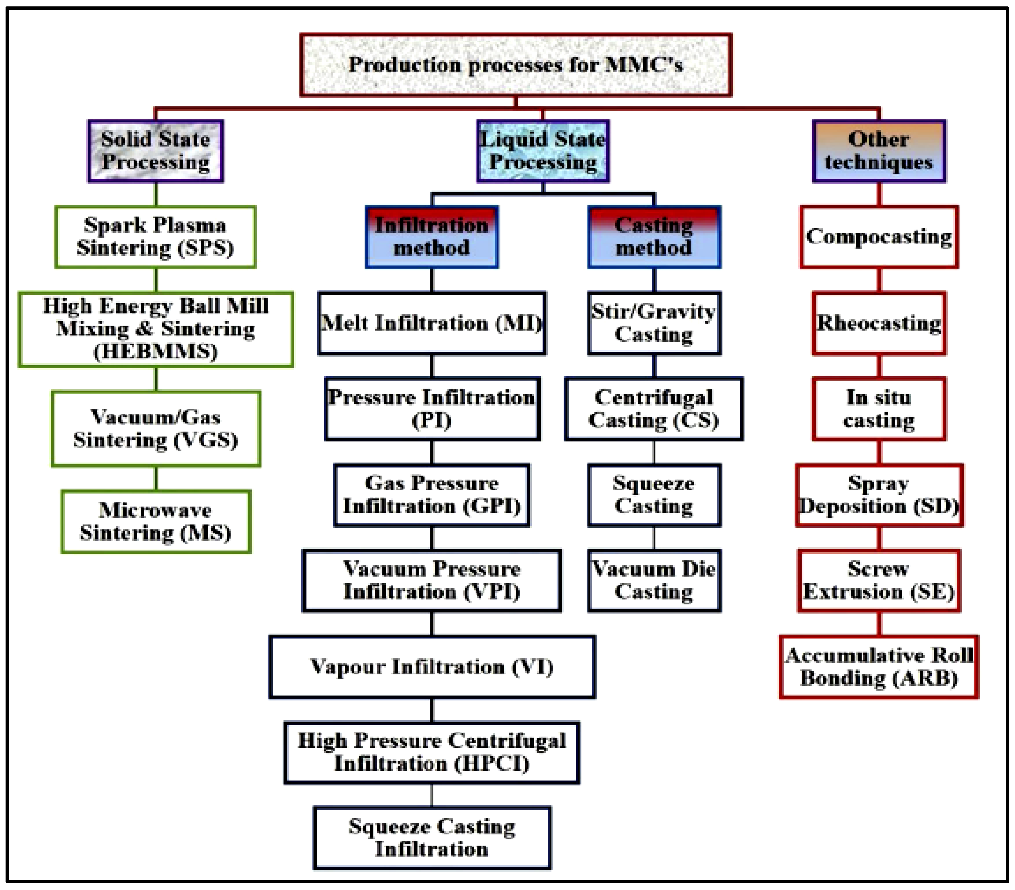
Figure 1. Classification of several MMC production procedures. Reprinted from Ref. [13], with written permission from Elsevier Ltd. Copyright 2019.
Alloys 04 00018 g001
Figure 2. Stir casting process set-up under modified inert atmosphere. Reprinted from Ref. [13], with written permission from Elsevier Ltd. Copyright 2019.
Alloys 04 00018 g002
Figure 3. Two-step stir casting. Reprinted from Ref. [13], with written permission from Elsevier Ltd. Copyright 2019.
Alloys 04 00018 g003
Figure 4. Pinning of grain development in reinforcement matrix. Reprinted from Ref. [146], with written permission from Elsevier Ltd. Copyright 2020.
Alloys 04 00018 g004
Figure 5. SEM micrograph of LM13 alloy displaying SiC and ZrSiO4 (a) 1:3 ratio (b) 1:1 ratio primary phase dendrite distribution. Reprinted from Ref. [152], with written permission from Elsevier Ltd. Copyright 2018.
Alloys 04 00018 g005
Figure 6. SEM micrograph of LM13 alloy displaying hypoeutectic SiC and ZrSiO4 (3:1 ratio) primary phase dendrite distribution. Reprinted from Ref. [152], with written permission from Elsevier Ltd. Copyright 2018.
Alloys 04 00018 g006
Figure 7. SEM image WC and ZrSiO4 nanoparticles reinforced composite using stirred passes (a) base metal A7075 (b) after 2-pass (c) after 4-pass (d) after 6-pass. Reprinted from Ref. [160], with written permission from Elsevier Ltd. Copyright 2021.
Alloys 04 00018 g007
Figure 8. SEM micrographs of the Al7075/WC/ZrSiO4 (nano-powders) composite (a) low pass (b) high pass morphology of Al2O3/Al powders after 6 h ball milling time. Reprinted from Ref. [160], with written permission from Elsevier Ltd. Copyright 2021.
Alloys 04 00018 g008
Figure 9. Optical micrographs of grains-structure (a) 150 °C (b) 190 °C. Reprinted from Ref. [146], with written permission from Elsevier Ltd. Copyright 2020.
Alloys 04 00018 g009
Figure 10. XRD image after 6-pass of Al7075/WC/ZrSiO4 composite. Reprinted from Ref. [160], with written permission from Elsevier Ltd. Copyright 2021.
Alloys 04 00018 g010
Figure 11. SEM and EDS mapping of nano composite: (a) Micro images (b) EDS mapping of carbon element (c) EDS mapping of Aluminium element (d) EDS mapping of silicon element. Reprinted from Ref. [146], with written permission from Elsevier Ltd. Copyright 2020.
Alloys 04 00018 g011
Figure 12. TEM images of water-FSPed composite (a) recovery structure (b) sub-boundary dislocations (c) developed sub-grain boundaries (d) high dislocation gen erated with Ti particle into matrix. Reprinted from Ref. [146], with written permission from Elsevier Ltd. Copyright 2020.
Alloys 04 00018 g012
Figure 13. XRD patterns of worn surfaces after reciprocating sliding against ZrO2 ball for AZ91D alloy and AZ91D surface composites reinforced with Y2O3/HA, HA/ZrO2, and Y2O3/ZrO2. Reprinted from Ref. [166], with written permission from Elsevier Ltd. Copyright 2025.
Alloys 04 00018 g013
Figure 14. XRD patterns of worn surfaces after reciprocating sliding against Si3N4 ball for AZ91D alloy and AZ91D surface composites reinforced with Y2O3/HA, HA/ZrO2, and Y2O3/ZrO2. Reprinted from Ref. [166], with written permission from Elsevier Ltd. Copyright 2025.
Alloys 04 00018 g014
Figure 15. Hardness of AZ91D alloy and dual reinforced composites. Reprinted from Ref. [166], with written permission from Elsevier Ltd. Copyright 2025.
Alloys 04 00018 g015
Figure 16. Tensile strength of Al7075/WC/ZrSiO4 composites. Reprinted from Ref. [160], with written permission from Elsevier Ltd. Copyright 2021.
Alloys 04 00018 g016
Figure 17. Slurry erosive wear of FSP sample with 20%, 40%, 60% slurry concentration of fine silica sand (a) 1000 RPM (b) 1500 RPM (c) 2000 RPM. Reprinted from Ref. [160], with written permission from Elsevier Ltd. Copyright 2021.
Alloys 04 00018 g017
Figure 18. Slurry erosive wear of FSP sample with 20%, 40%, 60% slurry concentration of medium silica sand (a) 1000 RPM (b) 1500 RPM (c) 2000 RPM. Reprinted from Ref. [160], with written permission from Elsevier Ltd. Copyright 2021.
Alloys 04 00018 g018
Figure 19. Wear profile of the specimens with SEM micrograph of wear surface for composite (10% SiC and 5% ZrSiO4 particles) (a) 50 (b) 60 and (c) 70-durometer with 25% slurry concentrations of fine silica quartz sand. Reprinted from Ref. [152], with written permission from Elsevier Ltd. Copyright 2018.
Alloys 04 00018 g019
Figure 20. Multidimensional images of graphene flakes (a) SEM (b) TEM images in powder form. Reprinted from Ref. [146], with written permission from Elsevier Ltd. Copyright 2020.
Alloys 04 00018 g020
Figure 21. Comparison of ultimate tensile strength for different FSPed composites. Reprinted from Ref. [146], with written permission from Elsevier Ltd. Copyright 2020.
Alloys 04 00018 g021
Figure 22. Tensile fractography of SEM micrographs fracture surface (a) micro composite (b) nano composite (c) FSPed micro composite (d) FSPed nano composite. Reprinted from Ref. [146], with written permission from Elsevier Ltd. Copyright 2020.
Alloys 04 00018 g022
Figure 23. The mass loss of (a) composite A, (b) composite B, (c) composite C for one hour rotation in 25% fine sand at 200 rpm, and graph (d) represents the summery of a,b,c. Reprinted from Ref. [152], with written permission from Elsevier Ltd. Copyright 2018.
Alloys 04 00018 g023
Figure 24. Wear profile of the specimens with a tool feed rate of 40 mm/min (a) 2 N (b) 5 N (c) EDS analysis of the specimens. Reprinted from Ref. [146], with written permission from Elsevier Ltd. Copyright 2020.
Alloys 04 00018 g024
Figure 25. SEM micrographs of worn surfaces (ac) without reinforcement (df) with reinforcement. Reprinted from Ref. [146], with written permission from Elsevier Ltd. Copyright 2020.
Alloys 04 00018 g025
Figure 26. P-N curve of Al-7075 alloy at 72.5 N-m torque. Reprinted from Ref. [146], with written permission from Elsevier Ltd. Copyright 2020.
Alloys 04 00018 g026
Figure 27. Fracture surfaces (A) uncoated specimen, 255 MPa, 101,123 cycles (B) DLC coated specimen, 237 MPa, 618,000 cycles at room temperature. Reprinted from Ref. [146], with written permission from Elsevier Ltd. Copyright 2020.
Alloys 04 00018 g027
Figure 28. Stress-life curves of pre-corrosion specimens for (a) R = 0.5 and (b) R = 0.06. Arrows on data points indicate run-outs. Reprinted from Ref. [146], with written permission from Elsevier Ltd. Copyright 2020.
Alloys 04 00018 g028
Figure 29. Uncoated fracture surface at 275 MPa load with 74,007 cycles. Reprinted from Ref. [146], with written permission from Elsevier Ltd. Copyright 2020.
Alloys 04 00018 g029
Figure 30. S-N curve of TiB2/A356 composite and base alloy. Reprinted from Ref. [221], with written permission from Elsevier Ltd. Copyright 2012.
Alloys 04 00018 g030
Figure 31. Crack initiation in TiB2/A356 composite at 70 MPa represented by (a) circles, (b) inclusion with pores near the surface (c) fractured Eutectic-Si. Reprinted from Ref. [221], with written permission from Elsevier Ltd. Copyright 2012.
Alloys 04 00018 g031
Figure 32. Fatigue life for repaired and un-repaired surface at fixed loading. Reprinted from Ref. [146], with written permission from Elsevier Ltd. Copyright 2020.
Alloys 04 00018 g032
Figure 33. Crack development rate vs. range of factor of stress intensity for A356 alloy and TiB2/AA356 composite: (a) striations in A356alloy, (b) with cracked eutectic Si particle A356/TiB2 composite and (c) unbroken TiB2 particles. Reprinted from Ref. [221], with written permission from Elsevier Ltd. Copyright 2012.
Alloys 04 00018 g033
Figure 34. Crack propagation in TiB2/A356 composite and A356 alloy: (a) AA356 ductile fracture (b) de-bonded and cracked eutectic Si particle in A356/TiB2 composite, and (c) separation of TiB2 particles. Reprinted from Ref. [221], with written permission from Elsevier Ltd. Copyright 2012.
Alloys 04 00018 g034
Figure 35. Creep strain rates of Al-7075 alloy with and without LSP treatment at various temperatures and stresses (a) 150 °C and 350 MPa (b) 200 °C and 300 MPa (c) 200 °C and 350 MPa. Reprinted from Ref. [146], with written permission from Elsevier Ltd. Copyright 2020.
Alloys 04 00018 g035
Figure 36. Tensile-creep curves of Al-7075 alloy at temperatures (a) 393 K (b) 423 K. Reprinted from Ref. [146], with written permission from Elsevier Ltd. Copyright 2020.
Alloys 04 00018 g036
Figure 37. Predicted and achieved creep strains of Al-7075 alloy with creep temperatures for 100 h (a) 393 K and (b) 423 K. Reprinted from Ref. [146], with written permission from Elsevier Ltd. Copyright 2020.
Alloys 04 00018 g037
Figure 38. Life-time results on three combined-loading at low-frequency loads (a) 0.4 Hz (b) 1 Hz. Reprinted from Ref. [146], with written permission from Elsevier Ltd. Copyright 2020.
Alloys 04 00018 g038
Figure 39. Failure after amplitude growth (a) secondary cracks formation with plastic deformation (b) non-metallic enclosure as crack starter. Reprinted from Ref. [146], with written permission from Elsevier Ltd. Copyright 2020.
Alloys 04 00018 g039
Figure 40. (ag) Usual SEM fractographs for the multi-crack initiation on surface with 120 h loading time. Reprinted from Ref. [146], with written permission from Elsevier Ltd. Copyright 2020.
Alloys 04 00018 g040
Table 1. Cost performance comparison of AMMC methods [6,8,19].
MethodEquipment CostEnergy UseReinforcement EfficiencyIdeal Volume
Stir CastingLowLowModerate (agglomeration)>10,000 units
Powder MetallurgyHighMediumHigh (uniform dispersion)<1000 units
Additive Mfg.Very HighVery HighExcellent (hybrid scales)Prototypes
Green CompositesMediumLowModerate (waste compatibility)Medium scale
Table 2. AMMCs formed from Al-matrix and different reinforcement.
Composite MaterialParticle SizeProcessing MethodChange in PropertiesYear and Reference
Al6061/FA1–2 µmCompo-castingImproved micro hardness and UTS2013 [29]
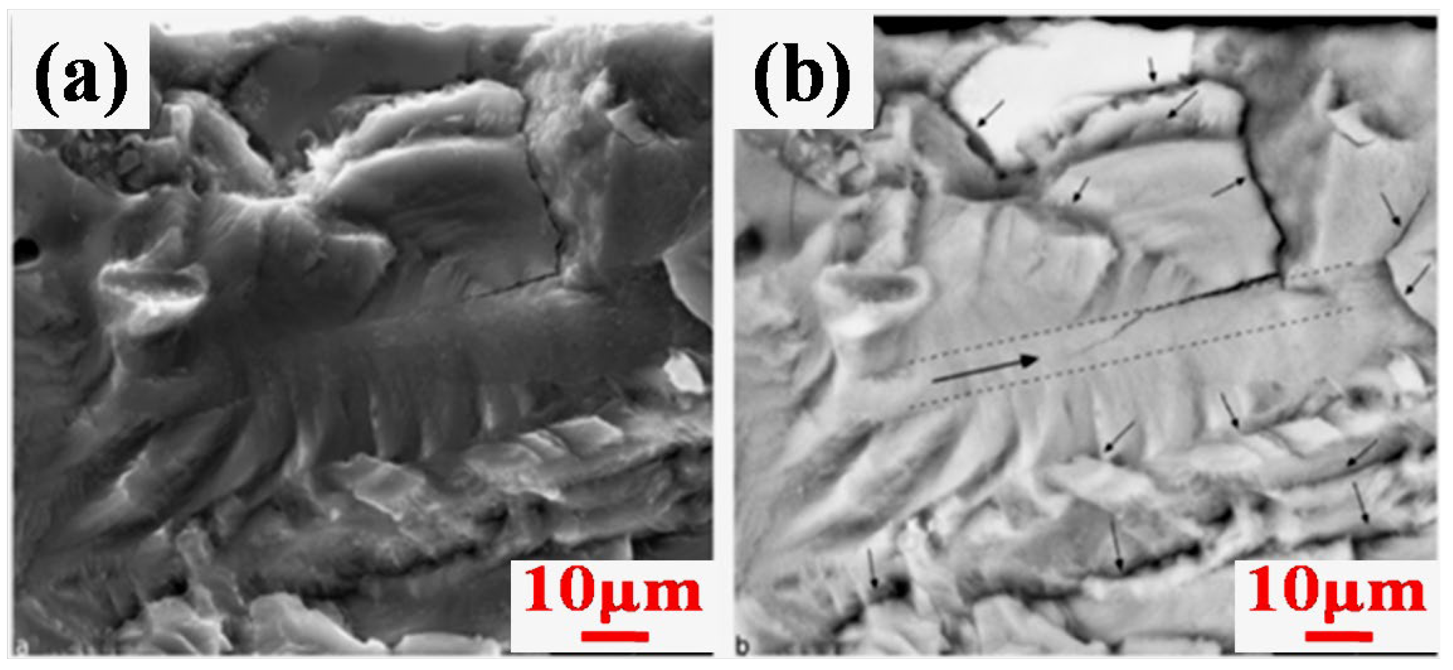
Al2024/Cr2O3 Friction stir processing (FSP)FSP reduced wear resistance without reinforcement and increased with rein2013 [30]
Al6062/NiTi(FSP, Aging treated, T-6 treated)150–178 and 2–74 µmFriction stir processing (FSP)Altered the tensile strength (increase, increases, decreases)2014 [31]
Al6061/Al2O3320 nmFSPIncreased micro hardness/increased tensile strength2014 [32]
Al7075/Al2O3/Gr45 µm/60 µmStir castingHardness increased/density increased/good wear behaviour2014 [33]
Al5052/Al2O3/TiB2500 nmFSPIncreased hardness/improved wear resistance2015 [34]
Al6061/RHA FSPIncreased micro-hardness2018 [35]
Al6063/nano-RHA Ultrasonic and stirringIncreased micro-hardness2018 [19]
Al6061/SiC/Coconut shell ash40–80 µmDouble stir castingIncreased tensile strength, increased hardness, increased compressive strength, decreased density2019 [37]
Al6061/RHA/Cu/Mg Two-step stir castingIncreased hardness, increased Tensile strength, decreased %elongation and impact strength2019 [38]
LM-13/B4C/K2TiF610 µmStir casting modified methodMacro and micro hardness enhanced, tensile strength enhanced2011 [Al22-14] [83]
Al6061/SiC/Gr125 µmStir castingGr addition reduced hardness and increases wear rate; SiC addition increased hardness and tensile strength and reduced wear rate; increased tensile strength2012 [Al22-19] [86]
ADC12/SiC30–40 µmStir castingMicro hardness enhanced and ultimate tensile strength enhanced2014 [89]
Al7075/SiC/Al2O3 Stir castingPorosity improved, surface roughness increased2014 [93]
Al6061/Al2O3125 µmStir castingHardness, tensile and yield strength increased, ductility decreases and at constant load of 19.62 N and 300 rpm, maximum wear rate was observed2014 [94]
Al6061/SiC
Al6061/SiC/Gr
37 µm–1 µm Al22 [41]
Al6061/SiC/FA/SiC-FA--Stir castingTensile strength increased, hardness increasedAl22 [70]
LM6/SiC/Al2O380–100/70–230Stir castingHardness increased, tribological properties improvedAl22 [72]
Al6061/SiC/TiB225 µm/10 µmStir castingHardness tensile strength, wear resistance and surface roughness improvedAl22 [80]
Table 3. Some applicable fabrication techniques with unique features and cost of AMMCs.
MethodCostApplicationComments
Stir castingLeast costApplicable for mass productionAppropriate for particulate reinforcement in AMMCs dependency on matrix metal and reinforcement properties and casting speed and duration
Powder metallurgyMedium costUsed in the production of parts that are heat resistant example piston, valvesMatrix metal and reinforcements are required in powder form. Due to no development of reactive zone, the manufactured AMMCs have high strength.
Diffusion BondingHigh costFor sheets, vane shafts and blades, this process is used.Suitable for matrix metal in the form of foils or sheets; reinforcements in the form filaments.
Liquid infiltrationLow costStructural component manufacturing such as rods, beam, tubesReinforcement in form of filament is used
Squeeze castingMedium cost Engine parts production, i.e., piston, connecting rods, cylinder headGenerally preferred for type of reinforcement. Used for mass scale production.
Compo-castingLow costApplicable to automobile industryConducive for discontinuous fibre in particle form
In situMedium costApplicable to automobile sectorIt results in distribution of reinforcing particle homogeneously.
Ultrasonic assisted castingHigh costSuitable for mesh shaped components. Preferred for large scale manufacturing.Almost uniform dispersion of particulate reinforcements.
Table 4. Comparative analysis of emerging reinforcement systems.
Reinforcement Type Key Benefit Performance Gain Primary Application
HEApStrength–ductility synergy+29% YS, +40% wear resistanceCorrosive environments
Agro-waste hybridsCost/environmental advantage55% hardness ↑, 20% material cost ↓Automotive non-structural
Nano planar defectsUltrahigh strength in 3D printsσ = 656 MPa post-agedAerospace lightweight parts
Ticore–shellDensity-compensated strengthσ = 1147 MPa at ρ = 3.7 g/cm3Defence, space structures
GrapheneMulti functionality2× thermal conductivity, 60% COF ↓Electronics, tribo systems
Disclaimer/Publisher’s Note: The statements, opinions and data contained in all publications are solely those of the individual author(s) and contributor(s) and not of MDPI and/or the editor(s). MDPI and/or the editor(s) disclaim responsibility for any injury to people or property resulting from any ideas, methods, instructions or products referred to in the content.