Article

Ultrasonic-Assisted Face Turning of C45 Steel: An Experimental Investigation on Surface Integrity

by
Thanh-Trung Nguyen
School of Mechanical Engineering, Hanoi University of Science and Technology, No 1 Dai Co Viet Street, Hanoi 100000, Vietnam
Alloys 2025, 4(3), 13; https://doi.org/10.3390/alloys4030013
Submission received: 23 May 2025 / Revised: 30 June 2025 / Accepted: 7 July 2025 / Published: 10 July 2025

Abstract

This study investigates the effect of ultrasonic vibration applied in the cutting speed direction on surface quality during face turning of C45 steel. The experiments were performed using an ultrasonic generator operating at a frequency of 20 kHz with an amplitude of approximately 10 µm. The cutting parameters used in the experiments included spindle speeds of 700, 1100, and 1300 rpm, feed rates of 0.1 and 0.15 mm/rev, while the depth of cut was fixed at 0.2 mm. Surface quality was evaluated based on the roughness parameters Ra and Rz, as well as surface topography was observed using a Keyence VHX-7000 digital microscope. The results show that ultrasonic-assisted face turning (UAFT) significantly improves surface finish, particularly in the central region of the workpiece where the cutting speed is lower and built-up edge (BUE) formation is more likely. The lowest Ra value recorded was 0.91 µm, representing a 71% reduction compared to conventional turning (CT). Furthermore, at the highest spindle speed (1300 rpm), the standard deviations of both Ra and Rz were minimal, indicating improved surface consistency due to the suppression of BUE by ultrasonic vibration. Topographical observations further confirmed that UAFT generated regular and periodic surface patterns, in contrast to the irregular textures observed in CT.

1. Introduction

Face turning is a widely used machining process for generating flat surfaces that are perpendicular to the rotational axis of a workpiece. It is commonly applied to components such as flanges, piston-end faces, punches, and other parts requiring high flatness and surface uniformity. The key parameters that govern the face turning process include spindle speed (n), depth of cut (ap), and feed rate (fr). Among these, cutting speed plays a critical role, exerting a highly variable and difficult-to-control influence on cutting force, the formation of BUE, and the resulting surface quality as it strongly depends on the characteristics of the material being machined [1,2,3]. Unlike cylindrical turning, where the cutting diameter remains constant, face turning involves a continuous change in cutting diameter (Dw) along the radial feed direction. As a result, the surface velocity varies depending on the machined diameter and is no longer a fixed value. It is calculated using the following equation:
v c = π D w n 1000
Here, Dw represents the instantaneous diameter at the cutting point, and n is the spindle speed. As the cutting tool moves radially toward the center of the workpiece, the effective diameter decreases, leading to a corresponding reduction in cutting speed. Conversely, at the outer edge of the workpiece, this speed is significantly higher due to the larger diameter. This variation across the face area results in inconsistencies in the cutting mechanism and surface quality. In particular, when machining near the center, the cutting speed can become very low, often leading to increased surface roughness and degraded surface quality.
While face turning is commonly encountered in practical machining tasks, especially for producing flat surfaces on rotational parts, it has received less in-depth research compared to cylindrical, conical, or thread turning. This is partly due to its relatively specific application scope and the complexities introduced by the variation in surface velocity across the machined surface. In components such as pipe flanges, where the center contains a large hole, the reduction in tool-workpiece relative motion is acceptable, allowing surface quality to be maintained. However, for solid shafts or punch tips that require machining all the way to the center, the issue becomes more critical, as the linear velocity of the cutting edge at the innermost region approaches nearly zero, often resulting in poor surface finish and inconsistent cutting behavior.
Ultrasonic-assisted turning (UAT) has been demonstrated to effectively improve surface finish and reduce cutting forces, particularly for machining difficult-to-cut materials such as nickel-based alloys [4,5], composite materials [6,7,8], and even low-carbon steels [9]. The fundamental principle of UAT involves superimposing high-frequency ultrasonic vibration onto the cutting tool, resulting in an intermittent cutting mechanism that contributes to the observed improvements. When the vibration is applied tangentially to the workpiece, the instantaneous cutting speed vins oscillates around vc, with an amplitude of 2πAf. Where A is the vibration amplitude and f is the vibration frequency [10], this relationship is described by the following equation:
v i n s = v c + 2 π A f c o s ( 2 π A f t + φ )
If v c 2 π A f , there will be time intervals during which the v i n s becomes zero or negative, resulting in intermittent cutting. This phenomenon can significantly reduce cutting forces and enhance surface quality; however, the material removal rate (MRR) is reduced, leading to longer machining times [11,12]. Most recent studies apply UAT within the low cutting speed region to maximize reductions in cutting forces and surface roughness [13,14,15]. Nevertheless, the applicability of UAT remains limited in industrial settings, where productivity is a critical factor. Although some recent studies have explored UAT at cutting speeds beyond the critical threshold of 2πAf, the majority have focused on cylindrical turning [16]. In the context of face turning, most investigations have still been conducted at relatively low value [17,18]. By contrast, the study in [19] performed face turning on aluminum matrix composites at a constant velocity of 100 and 150 m/min, applying axial vibration to the workpiece to generate surface textures aimed at improving frictional behavior. Notably, these turning tests did not reach the center of the workpiece but stopped 7.5 mm away in order to more easily maintain constant cutting speeds through CNC spindle speed control.
In a related study, Nouri et al. [20] also restricted the face turning process to a diameter range between 50 mm and 40 mm, thereby minimizing variation in cutting speed during machining. The material used was an Al7075-T6 aluminum alloy, and the distinctive feature of this work was the application of ultrasonic vibration in three different directions: 0°, 15°, and 30° relative to vertical. Their findings revealed that the micro-textured surfaces generated by UAFT exhibited enhanced wettability, owing to dimples acting “as reservoirs of liquid in comparison to untextured surfaces”.
Therefore, this work aims to investigate the effect of ultrasonic vibration applied in the direction of cutting speed on surface homogeneity during the face turning of C45 steel workpiece, within a spindle speed range of up to 1300 rpm. In particular, the experiments focus on evaluating improvements in surface roughness and structural characteristics near the central region of the workpiece, where machining quality is often significantly degraded due to extremely low tangential velocity.

2. Experimental Setup and Results

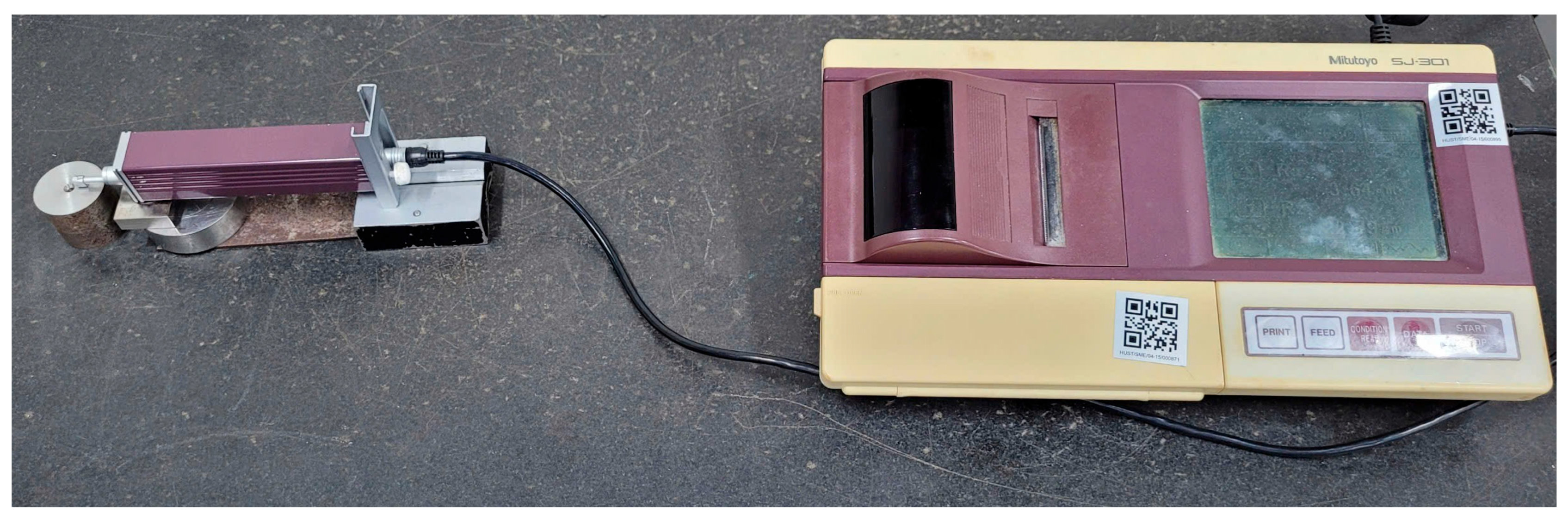
2.1. Experimental Setup

To investigate the effect of ultrasonic vibration on surface integrity in face turning, a series of experiments were conducted on a retrofitted conventional lathe (OKK Ramo). The experimental setup consisted of a vibration module delivering longitudinal ultrasonic excitation at 20 kHz frequency and 10 µm amplitude directly coupled to the turning insert. C45 steel shafts were used as workpiece materials, while carbide inserts with a nose radius of 0.8 mm were selected from Dormer Pramet to ensure consistency across tests. The cutting parameters (spindle speed, feed rate, and depth of cut) were varied systematically as listed in Table 1. Surface roughness was measured using a 2D roughness tester (Mitutoyo SJ-301), and surface integrity was observed via digital microscope (Keyence VHX 7000). Each roughness and vibration measurement were repeated three times to ensure repeatability.
After the face turning process was completed, the samples were sectioned, as illustrated in Figure 1, and surface roughness was measured, as shown in Figure 2.

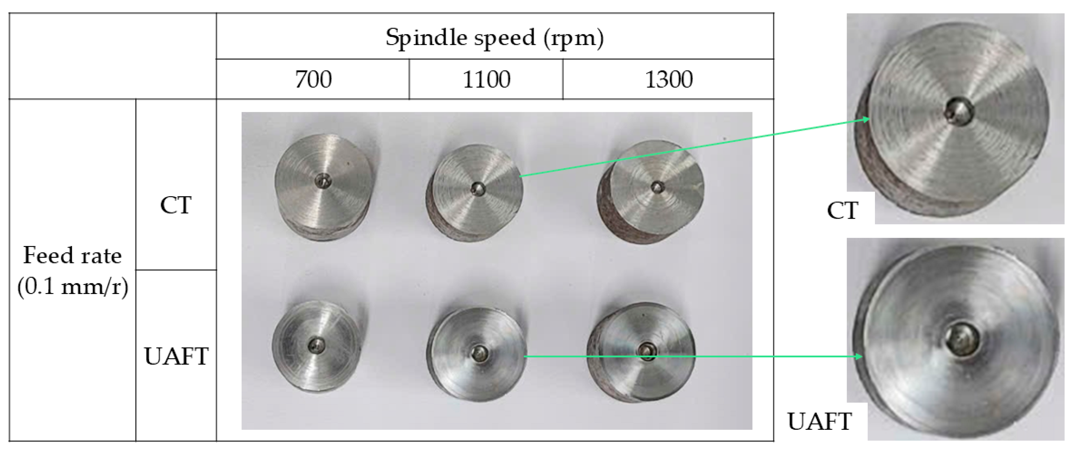
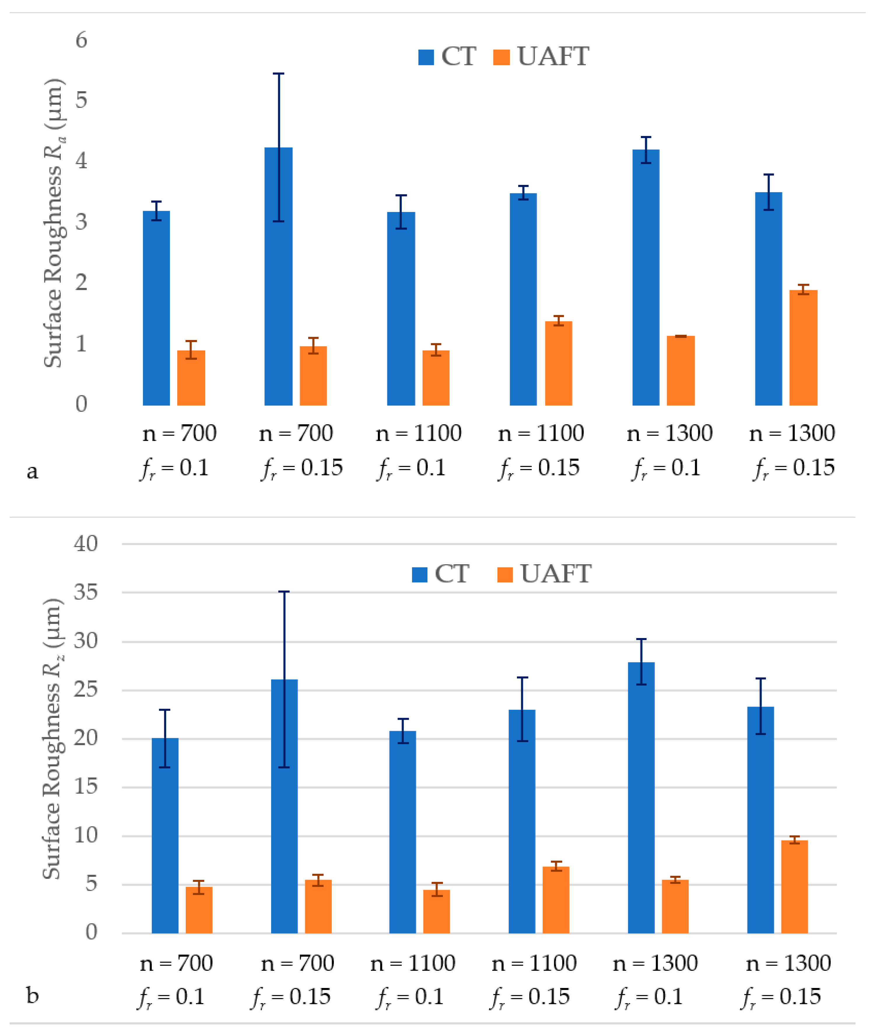
2.2. Surface Roughness

The resulting Ra and Rz values are presented in Figure 3. From the graphs, observations can be made as follows: In the CT method, surface roughness exhibited minimal variation with spindle speed in the range of 700 to 1300 rpm. This is because roughness was measured in the radial direction, which is perpendicular to the tool path. Since the actual cutting speed gradually decreases from the outer diameter toward the center, the speeds within this range are insufficient to overcome BUE formation—the primary cause of poor surface finish of medium carbon steel [21,22]. In the UAFT, surface roughness was strongly influenced by both spindle speed and feed rate. When vc ≤ 2πAf, a significant reduction in roughness was observed [7,13,23,24]. However, once this speed exceeded this threshold, the improvement in roughness compared to CT became marginal, although the resulting surface finish remained within an acceptable range [25].
The lowest mean Ra value obtained in the UAFT method was 0.91 µm, corresponding to the cutting parameters of n = 700 rpm and fr = 0.1 mm/rev, representing a 71% reduction compared to the equivalent value in CT. However, the standard deviation remained relatively high at 0.15 μm, as this level was entirely within the typical BUE formation zone. At the speeds below 60 m/min, the temperature at the rake face falls within the steel’s “blue-brittle” range, where ductility is reduced and shear failure is more likely [26]. Under high shear stress and hydrostatic pressure, material begins to accumulate on the rake face, forming an initial BUE layer. As cutting continues, new material slides along the tool but partially adheres, causing the BUE to gradually thicken. Once the adhesive limit is exceeded, the BUE detaches and may transfer to the machined surface, leading to increased roughness. Although UAFT effectively mitigates BUE, the phenomenon remains a rapidly recurring cyclic process at low speeds, which compromises the uniformity of the surface finish.
Conversely, at n = 1300 rpm and fr = 0.1 mm/rev, although Ra did not reach the minimum, the standard deviations of Ra and Rz were only 0.006 µm and 0.30 µm, respectively. These low variations indicate a highly consistent surface quality at high spindle speeds, primarily due to the significant reduction in the BUE phenomenon due to both high cutting speeds and assisted vibration.
An important observation lies in the ratio between Ra and Rz, which serves as an indicator of the surface texture characteristics. In conventional turning (CT), this ratio fluctuated around 15–16.3%, whereas in UAFT, it ranged from 17.9% to 20.3%. This suggests that surface asperities generated by CT tend to exhibit more irregular and sharper peaks, leading to a relatively higher Rz compared to Ra. In contrast, UAFT tends to produce more uniform and rounded peak formations, resulting in a higher Ra/Rz ratio. This inference is further supported by the roughness profiles shown in Figure 4 and is consistent with the findings of Thomas M. et al. [27], where a ratio of Rmax/Ra = 4.4 corresponds to a saw-tooth profile composed of regular, periodic peaks—indicative of stable cutting without BUE. Conversely, when the surface profile appears more random and irregular, a higher ratio of Rmax/Ra = 6.3 is observed, reflecting the presence of significant BUE effects. These results highlight that analyzing the relationship between Ra and Rz (or Rmax) provides not only a quantitative measure of surface roughness but also valuable insight into the underlying cutting mechanisms and stability of the machining process.
Notably, in Figure 4a, where the roughness probe scanned from the center outward in a CT sample, the first half (corresponding to lower cutting speeds) exhibited an unstable and irregular roughness pattern. In contrast, the second half (associated with higher speeds) displayed more regular and consistent peak formations. By comparison, Figure 4b for the UAFT sample demonstrates uniformly spaced roughness peaks across the entire profile. The distance between successive peaks closely matches the feed rate fr, implying that the BUE formation was effectively suppressed even in regions with low cutting speed, thereby confirming the stabilizing effect of ultrasonic assistance.

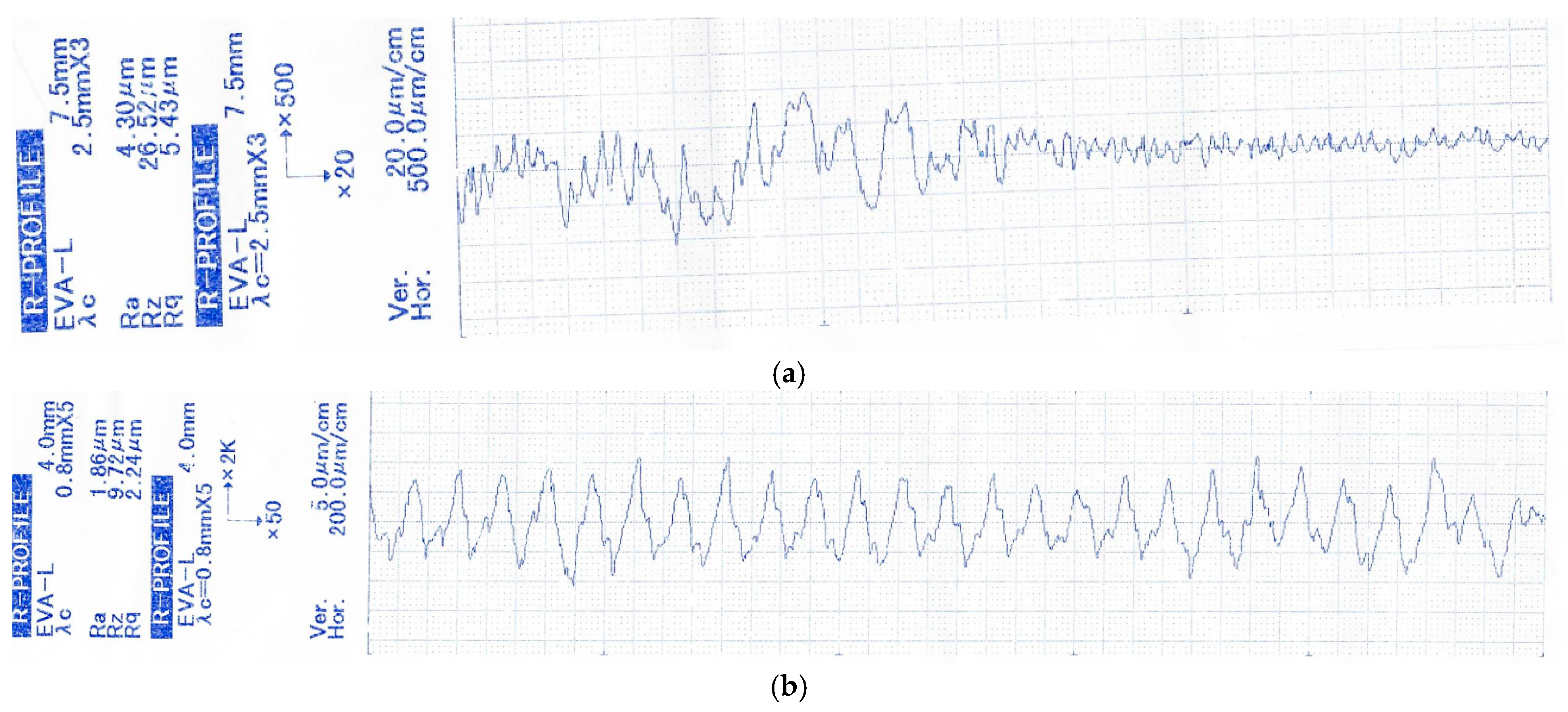
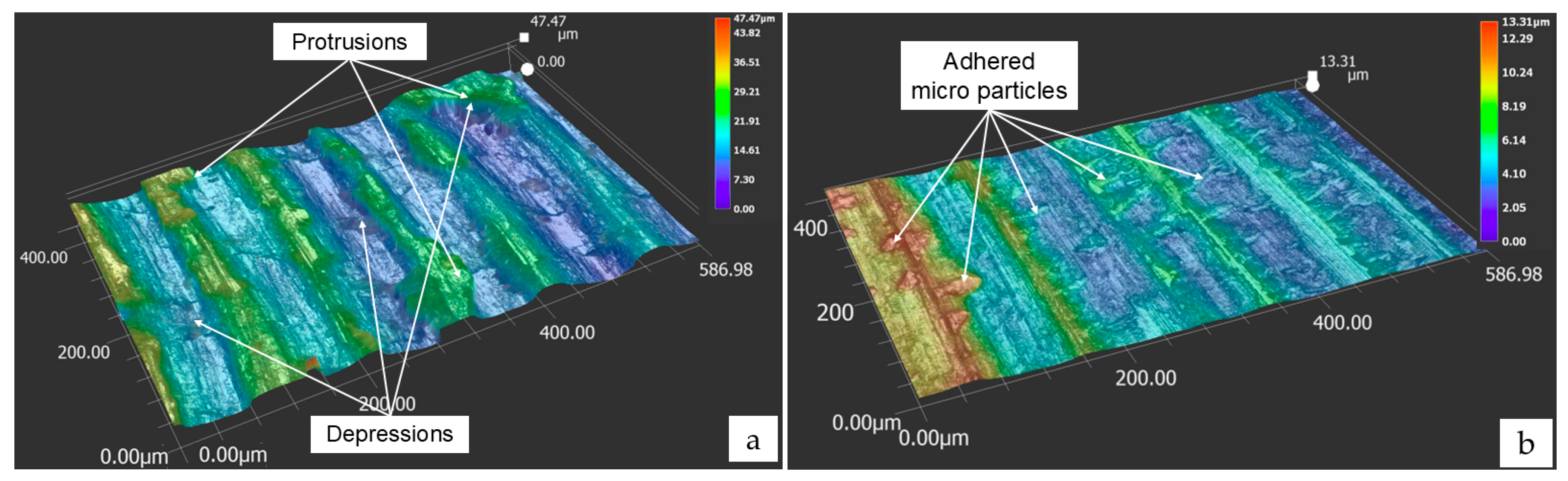
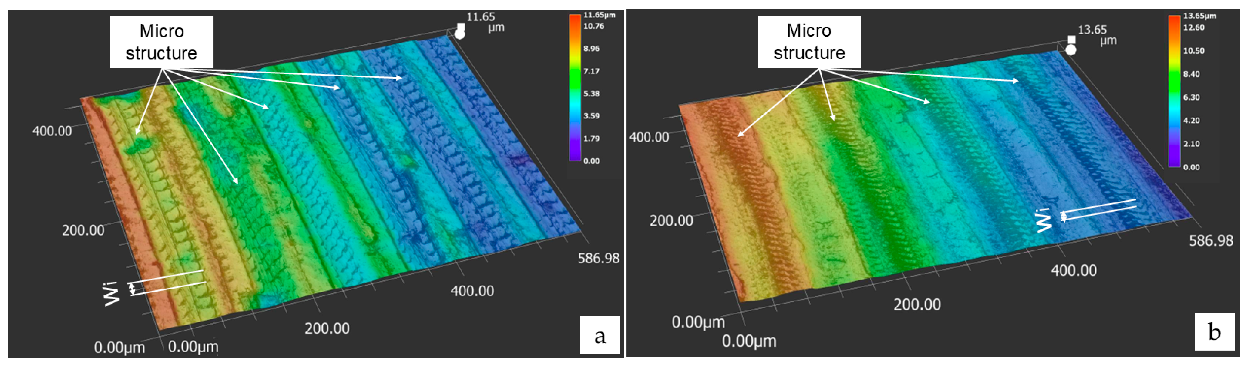
2.3. Surface Topography

Microscopic observations using the Keyence VHX-7000 digital microscope further support the previously discussed findings. In the CT method at a spindle speed of n = 1300 rpm, the surface near the center of the workpiece (Figure 5a) exhibits distinct tool marks corresponding to the feed rate (fr). However, the peak-to-valley height is considerably large, and the surface displays protrusions and depressions irregularly distributed along the cutting direction, indicative of material adhesion and unstable chip formation. These characteristics suggest the presence of a BUE, which contributes to increased surface roughness and the formation of surface irregularities.
Toward the outer region of the workpiece (Figure 5b), the height of the surface asperities is significantly reduced. Nevertheless, abnormal surface features oriented along the cutting speed direction are observed—commonly referred to as “adhered micro particle” by R. Tan [28]. This phenomenon is typically associated with lateral material deformation along the cutting edge and frequently occurs in conventional turning at high cutting speeds.
In contrast, surface observations of the samples machined using UAFT (Figure 6) show no signs of adhered micro particles. The peak-to-valley height is smaller than in CT and approaches the theoretical value calculated by the formula [29]:
R a = 0.0321 f r 2 R c
where Ra is the arithmetic mean height, fr is the feed rate, and Rc is the tool nose radius.
Additionally, theoretical and experimental studies, such as the one conducted in [25], have demonstrated that the ultrasonic vibration introduces periodic structures on the surface, with a wavelength given by:
w i = 1 0 6 × v c 60 × f
Here, w i represents the wavelength of the periodic structures formed on the machined surface by UAFT along the cutting direction, expressed in µm, and was found to exhibit negligible deviation from experimental results reported in [25]. In this equation, v c is calculated in m/min, and f is the frequency (in Hz) of the assisted ultrasonic vibration.

3. Conclusions

The effect of ultrasonic vibration assistance on surface quality during face turning of C45 steel was systematically investigated. The experimental results revealed that ultrasonic vibration significantly improved surface roughness, particularly in the area near the center of the workpiece where the cutting speed is extremely low. The lowest Ra value obtained in UAFT was 0.91 µm at a spindle speed of 700 rpm and a feed rate of 0.1 mm/rev, representing a reduction of up to 71% compared to CT.
The improvement in surface quality at low speeds is especially noteworthy, as CT under such conditions typically results in severe surface degradation, with high Ra and Rz values primarily due to the formation of BUE. However, with the application of ultrasonic vibration, BUE formation was significantly suppressed. Surface topography observations indicated that, in the UAFT method, roughness peaks appeared at regular intervals corresponding to the feed rate, and the machined surfaces exhibited uniform microstructures, attributed to the modulation of instantaneous cutting speed by ultrasonic vibration.

Funding

This research received no external funding.

Institutional Review Board Statement

Not applicable.

Informed Consent Statement

Not applicable.

Data Availability Statement

Data is contained within the article.

Acknowledgments

The authors would like to thank the Precision Engineering and Smart Measurements Laboratory at Hanoi University of Science and Technology for their support in conducting the turning operations as well as the surface roughness and vibration amplitude measurements.

Conflicts of Interest

The author declares no conflicts of interest.

Nomenclature

AUltrasonic vibration amplitude (µm)
fFrequency of ultrasonic vibration (Hz)
frFeed rate in Conventional Turning (CT) (mm/rev)
RaArithmetic Mean Height (µm)
RzTen-point Mean Height (µm)
vcCutting speed in Conventional Turning (m/min)
vinsInstantaneous cutting speed with ultrasonic vibration assistance
vcriticalCritical cutting speed (m/min)
nSpindle speed of lathe (r/min)
apDepth of cut
RcNose radius of turning insert
wiThe wavelength of the periodic microstructure

Abbreviations

The following abbreviations are used in this manuscript:
UAFTUltrasonic Assisted Face Turning
CTConventional Turning

References

  1. Muñoz-Escalona, P.; Cassier, Z. Influence of the critical cutting speed on the surface finish of turned steel. Wear 1998, 218, 103–109. [Google Scholar] [CrossRef]
  2. Esteves Correia, A.; Paulo Davim, J. Surface roughness measurement in turning carbon steel AISI 1045 using wiper inserts. Measurement 2011, 44, 1000–1005. [Google Scholar] [CrossRef]
  3. Frăţilă, D.; Caizar, C. Investigation of the Influence of Process Parameters and Cooling Method on the Surface Quality of AISI-1045 during Turning. Mater. Manuf. Process 2012, 27, 1123–1128. [Google Scholar] [CrossRef]
  4. Kang, R.; Zhang, P.; Wei, Z.; Dong, Z.; Wang, Y. Experimental Study on Ultrasonic Assisted Turning of GH4068 Superalloy. Materials 2023, 16, 3554. [Google Scholar] [CrossRef]
  5. Khanna, N.; Airao, J.; Nirala, C.K.; Krolczyk, G.M. Novel sustainable cryo-lubrication strategies for reducing tool wear during ultrasonic-assisted turning of Inconel 718. Tribol. Int. 2022, 174, 107728. [Google Scholar] [CrossRef]
  6. Bertolini, R.; Andrea, G.; Alagan, N.T.; Bruschi, S. Tool wear reduction in ultrasonic vibration-assisted turning of SiC-reinforced metal-matrix composite. Wear 2023, 523, 204785. [Google Scholar] [CrossRef]
  7. Zhang, B.; Chen, G.; Chen, Z.; Hu, G.; Lv, Y.; Li, H. Ultrasonic elliptic vibration assisted turning SiCp/Al composite surface morphology. J. Manuf. Process 2025, 141, 1071–1083. [Google Scholar] [CrossRef]
  8. Liu, C.; Wang, W.; Xiong, Y.; Huang, B.; Li, L. Experimental investigation on tool wear in ultrasonic vibration-assisted turning of SiCf/SiC ceramic matrix composite. Int. J. Adv. Manuf. Technol. 2023, 125, 3081–3101. [Google Scholar] [CrossRef]
  9. Bui, A.T.; Nguyen, T.H.; Le, T.K.; Nguyen, T.-H. Investigation of surface topography in ultrasonic-assisted turning of C45 carbon steel. Jpn. J. Appl. Phys. 2024, 63, 016501. [Google Scholar] [CrossRef]
  10. Schubert, A.; Nestler, A.; Pinternagel, S.; Zeidler, H. Influence of ultrasonic vibration assistance on the surface integrity in turning of the aluminium alloy AA2017. Materials. Sci. Eng. Technol. 2011, 42, 658–665. [Google Scholar] [CrossRef]
  11. Jain, N.K.; Jain, V.K. Modeling of material removal in mechanical type advanced machining processes: A state-of-art review. Int. J. Mach. Tools Manuf. 2001, 41, 1573–1635. [Google Scholar] [CrossRef]
  12. Kumar, R.; Bilga, P.S.; Singh, S. Multi objective optimization using different methods of assigning weights to energy consumption responses, surface roughness and material removal rate during rough turning operation. J. Clean. Prod. 2017, 164, 45–57. [Google Scholar] [CrossRef]
  13. Xu, Y.; Gao, F.; Zou, P.; Zhang, Q.; Fan, F. Theoretical and experimental investigations of surface roughness, surface topography, and chip shape in ultrasonic vibration-assisted turning of Inconel 718. J. Mech. Sci. Technol. 2020, 34, 3791–3806. [Google Scholar] [CrossRef]
  14. Khajehzadeh, M.; Boostanipour, O.; Razfar, M.R. Finite element simulation and experimental investigation of residual stresses in ultrasonic assisted turning. Ultrasonics 2020, 108, 106208. [Google Scholar] [CrossRef] [PubMed]
  15. Sharma, V.; Pandey, P.M. Optimization of machining and vibration parameters for residual stresses minimization in ultrasonic assisted turning of 4340 hardened steel. Ultrasonics 2016, 70, 172–182. [Google Scholar] [CrossRef]
  16. Yang, Z.; Zhu, L.; Zhang, G.; Ni, C.; Lin, B. Review of ultrasonic vibration-assisted machining in advanced materials. Int. J. Mach. Tools Manuf. 2020, 156, 103594. [Google Scholar] [CrossRef]
  17. Mirzabagherian, M.; Amini, S.; Bayat, M. Investigation of the Effects of Ultrasonic-Assisted Face Turning with CO2 Cooling on Cutting Forces, Residual Stress, and Surface Quality. Int. J. Lightweight Mater. Manuf. 2025, in press. [CrossRef]
  18. Amini, S.; Hosseinabadi, H.N.; Sajjady, S.A. Experimental study on effect of micro textured surfaces generated by ultrasonic vibration assisted face turning on friction and wear performance. Appl. Surf. Sci. 2016, 390, 633–648. [Google Scholar] [CrossRef]
  19. Eiselt, P.; Hirsch, S.J.; Ozdemir, I.; Nestler, A.; Grund, T.; Schubert, A.; Lampke, T. Ultrasonic-Vibration-Superimposed Face Turning of Aluminium Matrix Composite Components for Enhancing Friction-Surface Preconditioning. J. Manuf. Mater. Process 2024, 8, 32. [Google Scholar] [CrossRef]
  20. Nouri, H.; Farahnakian, M.; Elhami, S. Experimental study on the wettability of microtextured surfaces generated by the ultrasonic-assisted face turning. Proc. Inst. Mech. Eng. Part J J. Eng. Tribol. 2017, 231, 655–663. [Google Scholar] [CrossRef]
  21. Lubis, S.Y.; Djamil, S.; Zebua, Y.K. Effect of cutting speed in the turning process of AISI 1045 steel on cutting force and built-up edge (BUE) characteristics of carbide cutting tool. Sinergi 2020, 24, 171. [Google Scholar] [CrossRef]
  22. Gómez-Parra, A.; Álvarez-Alcón, M.; Salguero, J.; Batista, M.; Marcos, M. Analysis of the evolution of the Built-Up Edge and Built-Up Layer formation mechanisms in the dry turning of aeronautical aluminium alloys. Wear 2013, 302, 1209–1218. [Google Scholar] [CrossRef]
  23. Puga; Hélder; Grilo, J.; Carneiro, V.H. Ultrasonic assisted turning of Al alloys: Influence of material processing to improve surface roughness. Surfaces 2019, 2, 326–335. [Google Scholar] [CrossRef]
  24. Sajjady, S.A.; Abadi, H.N.H.; Amini, S.; Nosouhi, R. Analytical and experimental study of topography of surface texture in ultrasonic vibration assisted turning. Mater. Des. 2016, 93, 311–323. [Google Scholar] [CrossRef]
  25. Nguyen, T.T.; Vu, T.T.; Nguyen, T.D. Surface Topography in Cutting-Speed-Direction Ultrasonic-Assisted Turning. Micromachines 2024, 15, 668. [Google Scholar] [CrossRef] [PubMed]
  26. Childs, T.H.C. Towards simulating built-up-edge formation in the machining of steel. CIRP. J. Manuf. Sci. Technol. 2011, 4, 57–70. [Google Scholar] [CrossRef]
  27. Thomas, M.; Beauchamp, Y.; Youssef, A.Y.; Masounave, J. An experimental design for surface roughness and built-up edge formation in lathe dry turning. Int. J. Qual. Sci. 1997, 2, 167–180. [Google Scholar]
  28. Tan, R.; Zhao, X.; Zhang, S.; Zou, X.; Guo, S.; Hu, Z.; Sun, T. Study on ultra-precision processing of Ti-6Al-4V with different ultrasonic vibration-assisted cutting modes. Mater. Manuf. Process 2019, 34, 1380–1388. [Google Scholar] [CrossRef]
  29. Boothroyd, G.; Knight, A. Fundamentals of Machining and Machine Tools, 2nd ed.; CRC Press: New York, NY, USA, 1988; p. 168. [Google Scholar]
Figure 1. Photographs of the machined workpiece surfaces under CT and UAFT.
Alloys 04 00013 g001
Figure 2. Surface roughness measurement using the Mitutoyo SJ301 tester (Kawasaki, Japan).
Alloys 04 00013 g002
Figure 3. Surface roughness results between CT and UAFT methods according to the parameters: (a) Arithmetic mean height Ra; (b) Ten-point mean height Rz.
Alloys 04 00013 g003
Figure 4. Surface roughness profile at: (a) CT with n = 1300 rpm, fr = 0.1 mm/r; (b) UAFT with n = 1300 rpm, fr = 0.15 mm/r.
Alloys 04 00013 g004
Figure 5. Three-dimensional surface structure machined by CT at n = 1300 rpm, fr = 0.1 mm/rev: (a) near the center of the workpiece; (b) at the periphery.
Alloys 04 00013 g005
Figure 6. Three-dimensional surface structures machined by UAFT at various cutting parameters: (a) n = 700 rpm, fr = 0.1 mm/rev; (b) n = 700 rpm, fr = 0.15 mm/rev; (c) n = 1100 rpm, fr = 0.15 mm/rev; (d) n = 1300 rpm, fr = 0.1 mm/rev.
Alloys 04 00013 g006aAlloys 04 00013 g006b
Table 1. Selected cutting parameters in CT and UAFT experiments.
No.Spindle Speed, n
(rpm)
Feed Rate, fr
(mm/r)
Depth of Cut, ap (mm)
17000.10.2
27000.150.2
311000.10.2
411000.150.2
513000.10.2
613000.150.2
Disclaimer/Publisher’s Note: The statements, opinions and data contained in all publications are solely those of the individual author(s) and contributor(s) and not of MDPI and/or the editor(s). MDPI and/or the editor(s) disclaim responsibility for any injury to people or property resulting from any ideas, methods, instructions or products referred to in the content.

