Article

Research on the Microstructure Evolution of TC4 Titanium Alloy Joint Fabricated by Continuous Drive Friction Welding

1
School of Materials Science and Engineering, Xi’an Shiyou University, 18 Dianzier Road, Xi’an 710065, China
2
CNPC Baoji Petroleum Pipe Industry Co., Ltd., Coiled Tubing Branch, Baoji 721000, China
3
College of Mechanical Engineering, Xi’an University of Science and Technology, Xi’an 710054, China
*
Author to whom correspondence should be addressed.
Submission received: 31 January 2025 / Revised: 5 March 2025 / Accepted: 11 March 2025 / Published: 14 March 2025

Abstract

:
In this paper, TC4 titanium alloy pipes were achieved by continuous drive friction welding, metallographic microscope and microhardness tester were used to evaluate the microstructure and the hardness of the joints, and the effect of friction pressure on the microstructure was studied. Under the selected welding parameters, all the joints have good morphology. The martensite is formed at the weld zone and the flash, which leads to a higher hardness on the weld zone. With the increase of friction pressure, the width of the weld zone, the grain size and LAGB (low angle grain boundary) at the weld zone decreases. In addition, dynamic recrystallization increases first, but when the friction pressure reaches 65 MPa, the deformation dominates.

1. Introduction

In the field of ultra-deep drilling, lightweight titanium alloy drill pipe has become a favored high-performance material, which is known for high-temperature resistance, corrosion resistance and excellent electrical conductivity. As a drill pipe, titanium alloy needs to be welded inevitably. However, titanium is easy to react with nitrogen, hydrogen and oxygen. Therefore, it is necessary to find a suitable welding method to connect titanium alloys. CDFW (Continuous drive friction welding) is selected due to the high quality and stability, as well as avoiding the defects in melting welding [1]. In actual production, a large number of joint cracks, pipes are more prone to rupture, seriously affecting product performance. In order to avoid the above problems, it is necessary to accurately select the CDFW parameters, which is crucial for the welding production of lightweight titanium alloy drill pipes.
At present, there are many reports on titanium alloy related to CDFW. Zhao et al. [2] took TB2 titanium alloy as the research object, carried out the linear friction welding experiment under the different welding pressures, the experiment result showed that the obvious recrystallization occurred at the two sides of the weld interface, and in the HAZ (heat-affected zone) of the joint, with the increase of welding pressure, the size of recrystallized grain and the width of weld zone decrease gradually, and the degree of grain deformation in heat affect. Zhang et al. [3] studied the effect of welding speed on the 7075 aluminum alloy joint welded by friction stir, and discovered that with the rise of welding speed, the grain size of nugget zone and heat engine impacted zone reduced. Xi et al. [4] prepared TC4 titanium alloy blind hole pipe using CDFW, and analyzed the effect of welding parameters on the flash morphology. The microstructure characteristics and mechanical properties of the joints in the heat treatment conditions also investigated. The results show that the welding parameters have little influence on the properties of the joints within the range of welding parameters tested in this research. The microstructure of the joint of the TC4 changes after welding from widmanstatten structure to the net basket structure, and the tensile strength reduced by 60 MPa. But the weld factor is still up to 0.94, and the plasticity and toughness are better than the base metal. Cheng et al. [5] studied the friction welding of TA18 titanium alloy pipe joint. The results show that the microstructure of rotary friction welding weld is acicular α phase due to severe plastic deformation in a short period. The HAZ structure consists of three phases: equiaxial α, partial acicular α’, and residual β. Chang et al. [6] studied the linear friction welding joint of TC21 titanium alloy. The results show that phase transformation and dynamic recrystallization occur in the WZ (weld zone). The thermal influence zone is mainly dominated by deformation α phase. With the distance from the weld center, the recrystallization degree weakens gradually, and the proportion of α phase increases gradually. Du et al. [7] studied the linear friction welding of TC17(α + β)/TC17(β) allogeneic titanium alloys. The results show that when the friction time is only 0.5 s, dynamic recrystallization occurs in the center of the welding interface and metastable β grains are formed. Wu et al. [8] studied the microstructure and properties of friction welding of TC4 titanium alloy joint. The results show that the weld zone is dominated by recrystallization structure, and the thermal influence zone has a rod-like primary αp phase. Gao et al. [9] studied the friction welding of Ti60/TC17 titanium alloys. The results show that dynamic recrystallization occurs on both sides of the weld interface. In the welded state, the structure of the weld is composed of acicular α slats and equiaxed grains, and the heat engine affected zone on both sides has obvious streamline morphology.
This paper uses CDFW to weld titanium alloy, and the microstructure and hardness distribution of the joint were studied. The results can provide theoretical guidance for the CDEW of titanium alloys, and also provide a strong theoretical basis for its safe application.

2. Materials and Methods

The test material is TC4 dual-phase titanium alloy pipe with a outer diameter of 73 mm, a wall thickness of 9 mm and a length of 150 mm. Since the cross section of the pipe is circular, CDFW is selected, and the main equipment is C400 continuous drive friction welding machine. The friction pressure of the machine can adjust from 0~400 kN. The parameters of the CDFW are shown in Table 1. The friction pressures of the three specimens are 45 MPa, 55 MPa and 65 MPa respectively, and the other welding parameters remain constant.
Metallographic samples were obtained by EDM (Electrical Discharge Machining) through the axis of the pipe, which were ground using 80~2000 sandpaper, and then polished by a polishing machine until the surface exhibited a metallic luster and mirror-like effect, without obvious scratches. Finally, the sample was etched by the corrosion solution of HF:HNO3 = 1:2 with the corrosion time of 4 s. The microstructure was observed from the left to the right by Leica DMI5000M optical microscope (Beijing Leboruijie Technology Co., Ltd., Beijing, China) [10].
In order to understand the distribution characteristics of hardness for each region, the Vickers hardness of the joint at the base metal, the heat-affected zone, the thermal heat-affected zone and weld zone was tested using a microhardness tester. HXD-1000TMC automatic turret microhardness (Shanghai Wanning Precision Scientific Instruments Co., Ltd., Shanghai, China) tester was used with a load of 500 g and a load holding time of 15 s [11]. The distribution of hardness in the joints is affected by the uneven temperature distribution at the friction surface, therefore, the distance between measurement points was set at 0.1 mm, and the hardness was recorded.
In order to characterize the effect of friction pressures on the properties of joints, EBSD (electron back scattering diffraction) was analyzed on the Zeiss SUPRA55 field emission scanning electron microscope (Carl Zeiss, Baden-Württemberg, Germany). The microstructure characteristic under different friction pressures were characterized to establish the logical relationship between mechanical properties and the friction pressures of the joint. Firstly, the samples were ground using 240~2000 sandpaper, then electropolished to make the surface smoothness meet the requirements of EBSD analysis.

3. Results

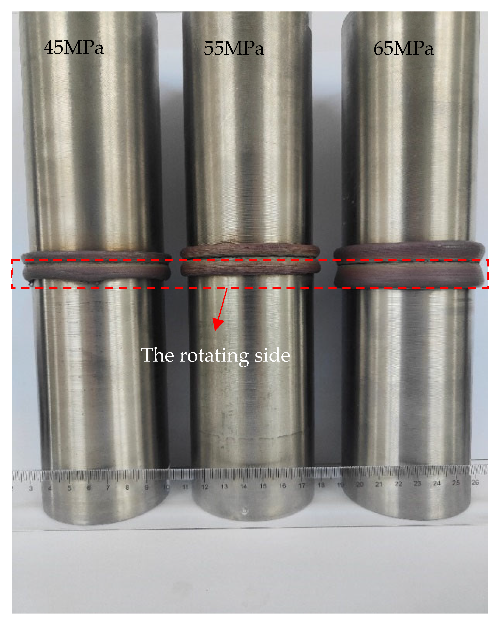
3.1. The Macroscopic Morphology of the Joint

Figure 1 shows the macroscopic morphology of TC4 joint achieved by CDFW at different friction pressures, including flash. It is seen that no cracks, porosity and other defects are found in the joint, which indicates that sound joints are obtained under different friction pressures. The flash, which is an important judgment basis for welding, is continuous and smooth at different friction pressures. While with increasing the friction pressure, the size of flash also increases, especially at the friction pressure of 65 MPa. In addition, the outer contour of the flash on the below, which is the rotating side, is larger than that of the fixed side. Therefore, the friction pressure has an impact on the morphology of the joint.

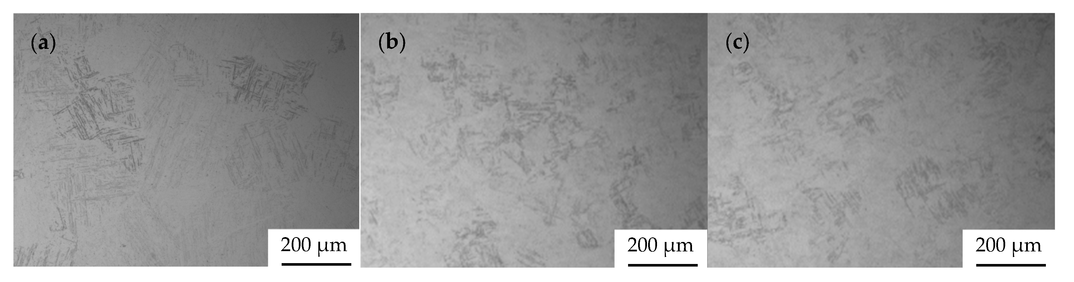
3.2. The Microstructure of Base Metal

Figure 2 is the microstructure of titanium alloy base metal. Figure 2a is the base metal of the rotating side, and the grains are equiaxed, and its plasticity and impact toughness are higher. Figure 2b is the base metal of the fixed side, and the alloy is widmanstatten structure, which is characterized by the fine and long structure in grains [11,12]. It has higher tensile properties and higher fracture toughness than ordinary martensitic steel.

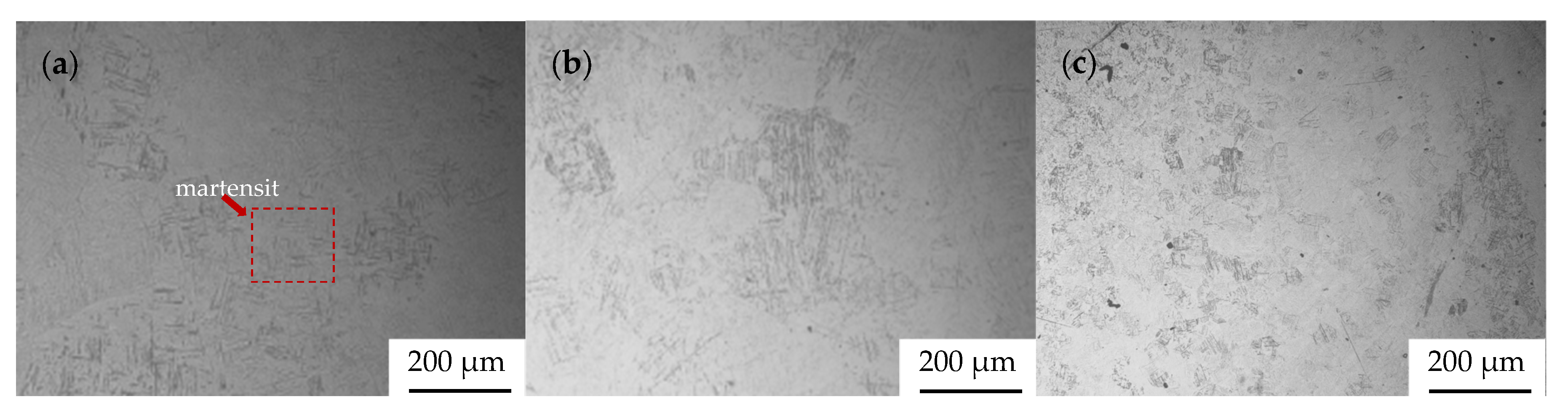
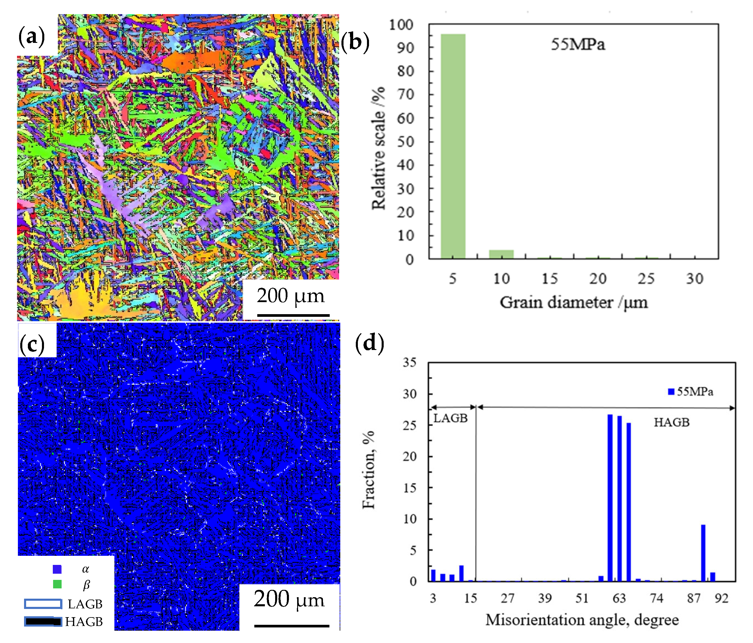
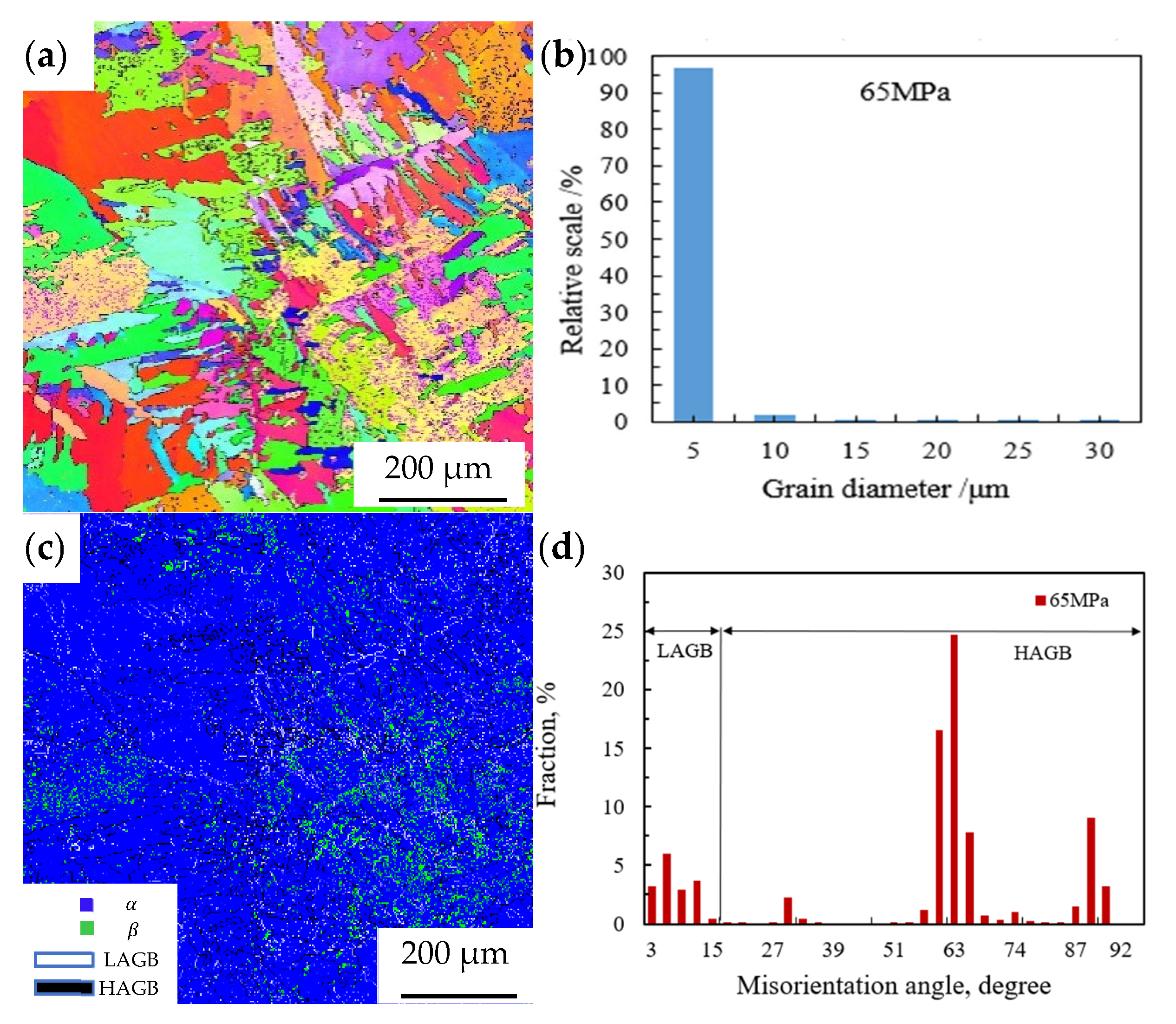
3.3. The Microstructure of Flash

Figure 3, Figure 4 and Figure 5 show the microstructure of flash at different friction pressures and positions. Compared with the base metal, the microstructure of the flash has changed obviously. When the friction pressure is 45 MPa, martensite appears in the entire flash as shown in Figure 3. With the increasing of friction pressure, martensite is also observed at the entire flash as shown in Figure 4 and Figure 5. During welding, the heat generated by friction causes the temperature to be above the β phase transition point, so the base metal first transforms into a high-temperature β phase. The cooling rate is very fast, therefore the high-temperature β phase transforms into martensite [13]. Compared with Figure 3, Figure 4 and Figure 5, it is found that with the increase of friction pressure, the martensite has no obvious change.

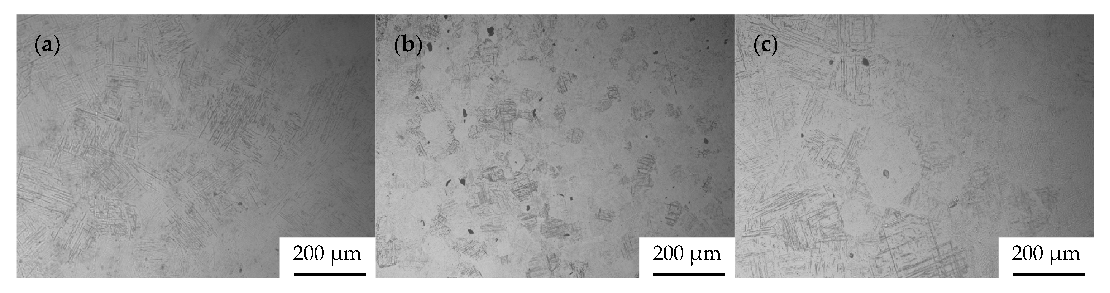
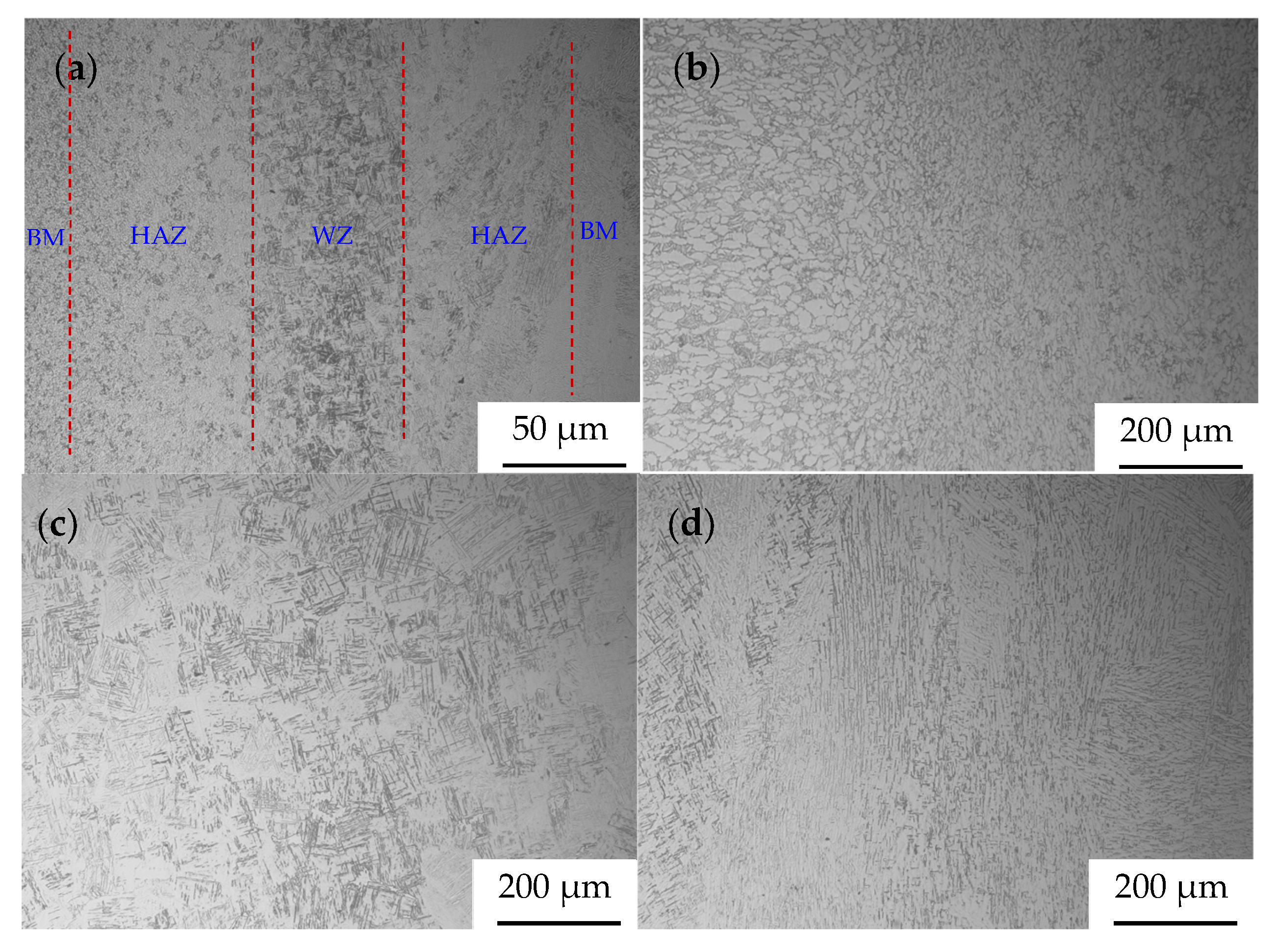
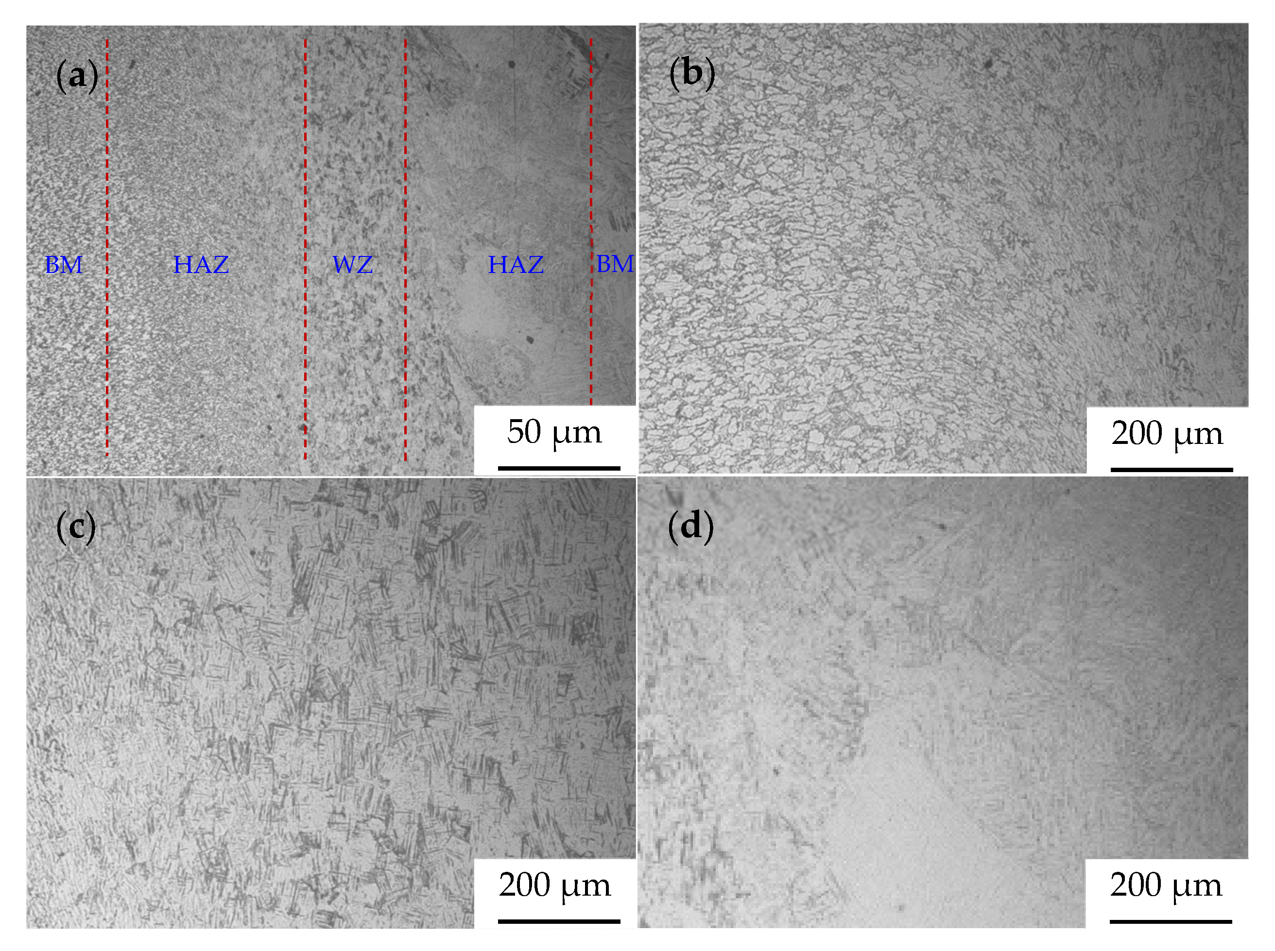
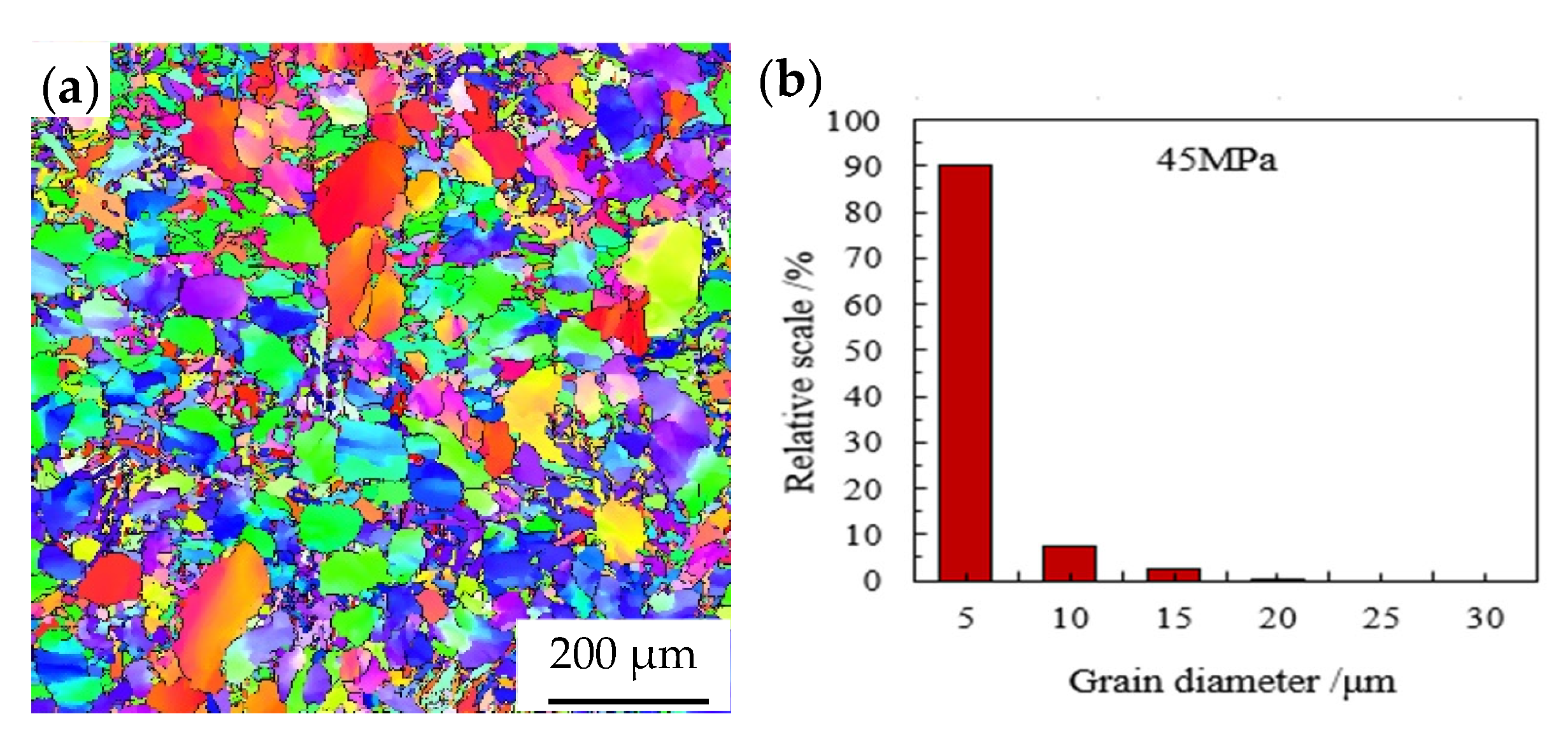
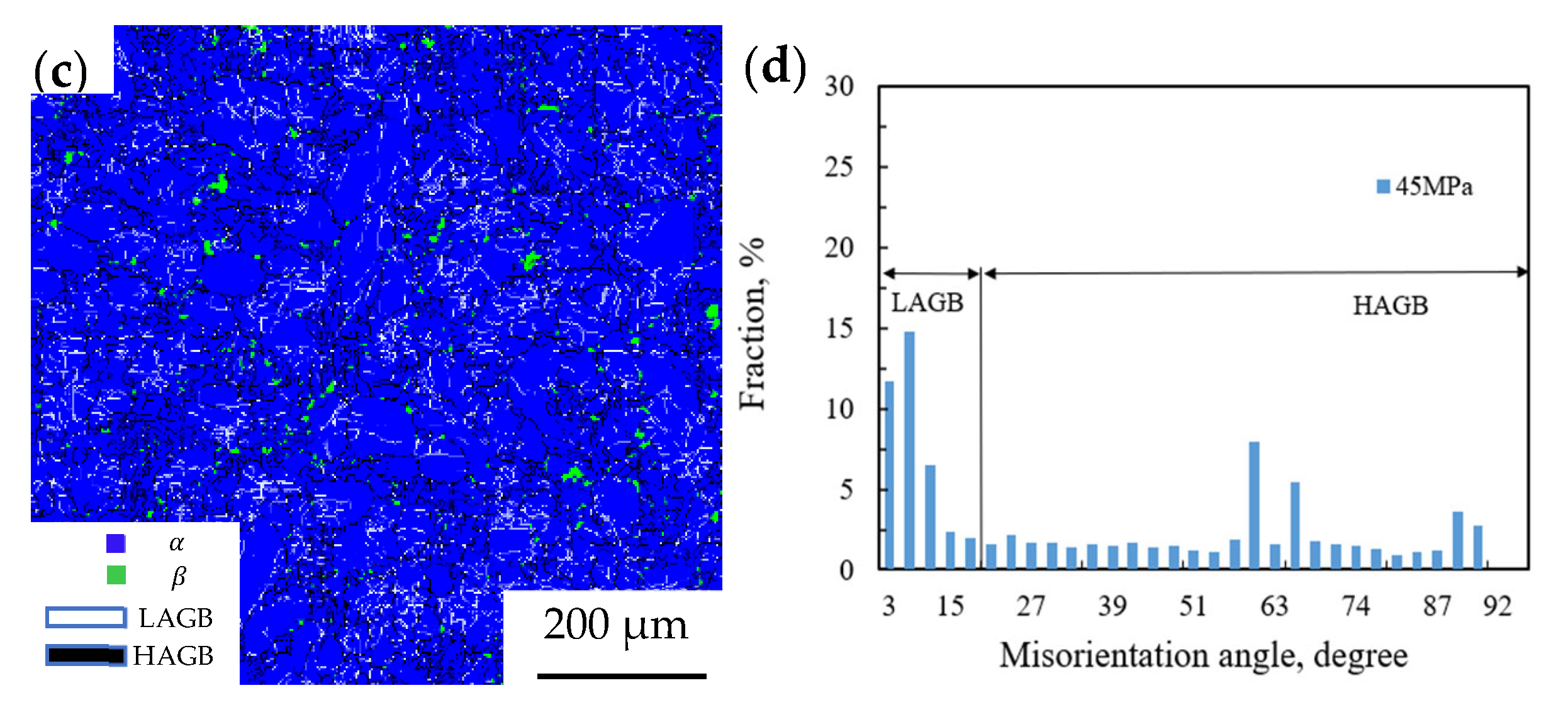
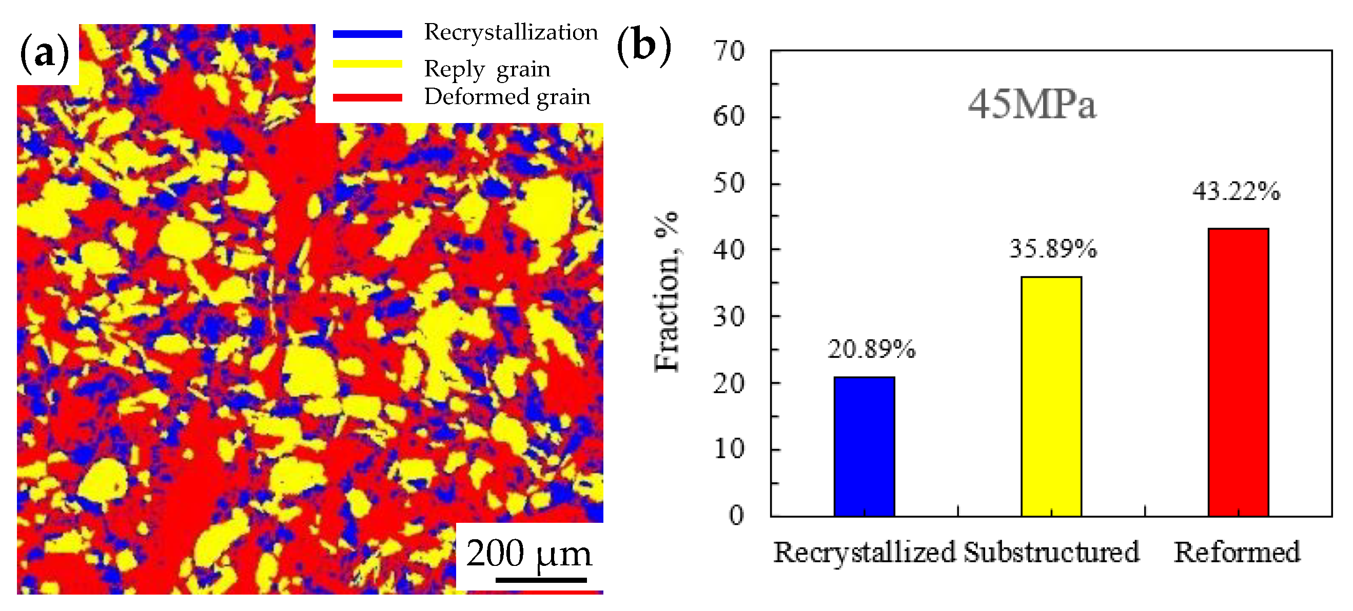
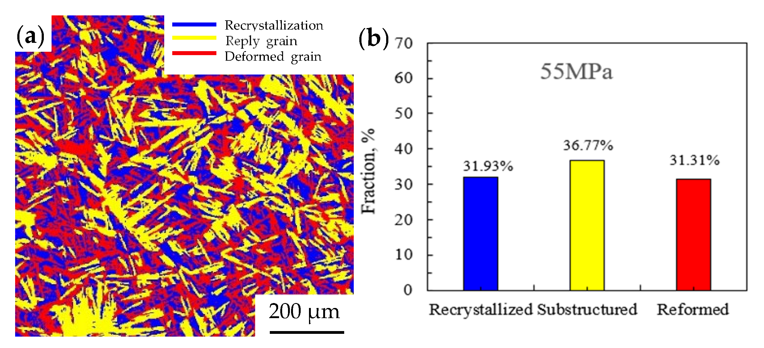
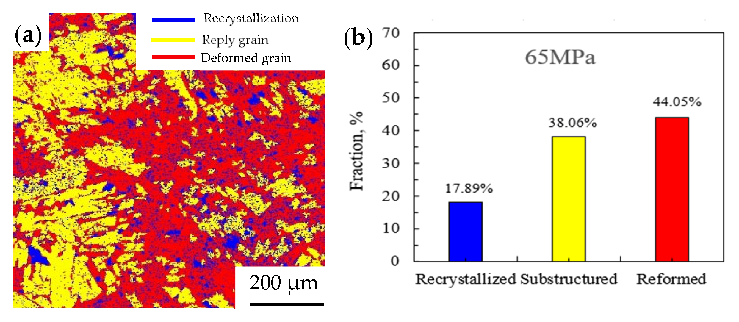
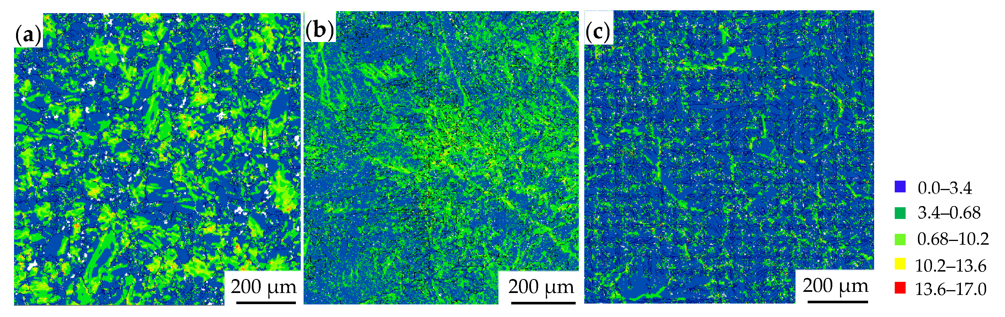
3.4. The Microstructure of Joints

Figure 6, Figure 7 and Figure 8 show the microstructure of the joint at different friction pressures and positions. Though the friction pressures are different, the joint consists of four zones, which are the base metal, the thermal mechanically affected zone, the HAZ and the WZ.
When the friction pressure is 45 MPa, the microstructure of the joint is shown in Figure 6. The width of the weld zone is about 55 µm, and is mainly composed of martensite as shown in Figure 6c. The equiaxial α phase at the thermal mechanically affected zone and HAZ is slightly deformed, that is, it is elongated as shown in Figure 6b. While significant deformation isn’t observed in lamellar α or β phases as shown in Figure 6d at the thermal mechanically affected zone and the heat-affected zone.
As the friction pressure increases to 55 MPa, the microstructure of the joint is shown in Figure 7. The width of weld zone is about 50 µm, which is narrower than that of the friction pressure of 45 MPa. Due to the higher the friction pressure, the greater the input power, the more plastic metal produced and extruded at the weld zone [14]. The microstructure of the weld zone is basically the same as that of the friction pressure of 45 MPa, which can be observed the martensite. There is more martensite in weld zone at the friction pressure of 55 MPa than at the friction pressure of 45 MPa. Compared with the friction pressure of 45 MPa, the thermal mechanically affected zone has a significant change at the friction pressure of 55 MPa. Obvious metal flow lines at the thermal mechanically affected zone are observed at the friction pressure of 55 MPa as shown in Figure 7b. This is because the degree of deformation increases as the frictional pressure increases, and a large number of grains slip, so that the equiaxial grains gradually elongate during the welding [15].
When the friction pressure continues to increase to 65 MPa, the width of weld zone is about 45 µm, and the microstructure of the joint is shown in Figure 8. It does not change significantly, that is, the microstructure of the joint was almost the same as that of friction pressure of 55 Mpa, which is mainly composed of martensite.
In order to further study the effect of friction pressure on the joint microstructure, EBSD analysis was carried out. Figure 9, Figure 10 and Figure 11 show the grain morphology, the grain size and the disorientation angle under different friction pressures, respectively. The average grain sizes of the joint were 7.5 μm, 6.3 μm, and 5.5 μm as shown in Figure 9a, Figure 10a and Figure 11a with increasing the friction pressure, respectively, which indicates that the friction pressure has a slight effect on the grain size. Lu et al. [16] also found that the grain size didn’t change obviously when the friction pressure changed. However, Wen [17] discovered that the most severe deformation occurred in the weld, promoting dynamic recrystallization of austenite and forming fine austenite and sub-crystal structure. In addition, at a friction pressure of 45 MPa, about 90% of the grain size is 5 μm. While at a friction pressure of 55 MPa and 65 MPa, the percentage of grains with a size of 5 μm has slightly increased and can reach 95–98%. Guo et al. [18] also found a similar trend in the TB2 titanium alloys.
In addition, the proportion of LAGB (at Figure 9c, Figure 10c and Figure 11c white lines) in the joint at a friction pressure of 45 MPa was more than 36.5%, while with the increasing of the friction pressure, the proportion of LAGB in the joint was only about 6.3% at Figure 10c,d and Figure 11c,d. With the increasing of the friction pressure, the LAGB reduces, and the HAGB (high angle grain boundary) increases significantly. Therefore, the friction pressure affected the microstructure of the weld zone in morphology and grain size [18].
It can be seen from Figure 12a, Figure 13a and Figure 14a that dynamic recrystallization occurs in the weld zone at different friction pressures. At a friction pressure of 45 MPa, the subgrains and the deformed grains are dominant in the weld zone as shown in Figure 12. When the energy accumulates to a certain extent and the temperature exceeds the recrystallization temperature, dynamic recrystallization occurs in a specific area of the interface [19]. When the friction pressure is 55 MPa, the recrystallized grains increase significantly, up to 31.93%, as shown in Figure 13, which is due to the increase of friction pressure. The higher the temperature at the weld zone, the wider the plastic deformation zone obtained, which is more conducive to the migration of grain boundaries and the diffusion of atoms, so recrystallization is also easy to carry out [20]. However, when the friction pressure increases to 65 MPa, as shown in Figure 14, the deformed grains increase significantly. The results show that with the increase of friction pressure, the recrystallization is sufficient. But when the pressure is high, the deformation dominates in the joint. Guo et al. [21] investigated that continuous dynamic recrystallization occurred in the dissimilar TA19/TB2 titanium alloy joint, and the mechanism is as follows: a large number of dislocations are activated in the weld zone during pyro plastic deformation. Dislocation multilateralization behavior occurs, and a large number of subgrains composed of small angle grain boundaries forms. In the subsequent deformation process of the metal, some small-angle grain boundaries in the subgrains continuously rotate to absorb dislocations and evolve into LAGB, thereby forming recrystallized grains. Therefore, the friction pressure can also affect the process of dynamic recrystallization and the deformation.
Under the coupling effect of frictional heat and forging force, recrystallization occurs on the friction surface [22], which leads to a decrease in dislocation density as shown in Figure 15. The dislocation densities of 0.0–3.4 × 10¹⁴/m2 were 54.6%, 56.2%, and 72.1% with increasing the friction pressures. Therefore, the friction pressure also has an effect on the dislocation density [23].
Figure 16 shows the pole figures at different friction pressures. The pole figures of (0001) and (10 1 ¯ 0) show that the texture intensity increases with the increase of friction pressure. Dai et al. [24] found a similar pattern in the study of TA15 laser welding microstructure and properties. When the friction pressure is 45 MPa, the texture intensity is 4.53. When the friction pressure increases to 55 MPa and 65 MPa, the texture intensity is 15.35 and 23.92, respectively. This may be due to the change of crystal orientation, grain size and grain boundary distribution with the increase of friction pressure, which leads to the change of texture intensity. Therefore, the texture intensity also affects by the friction pressure.

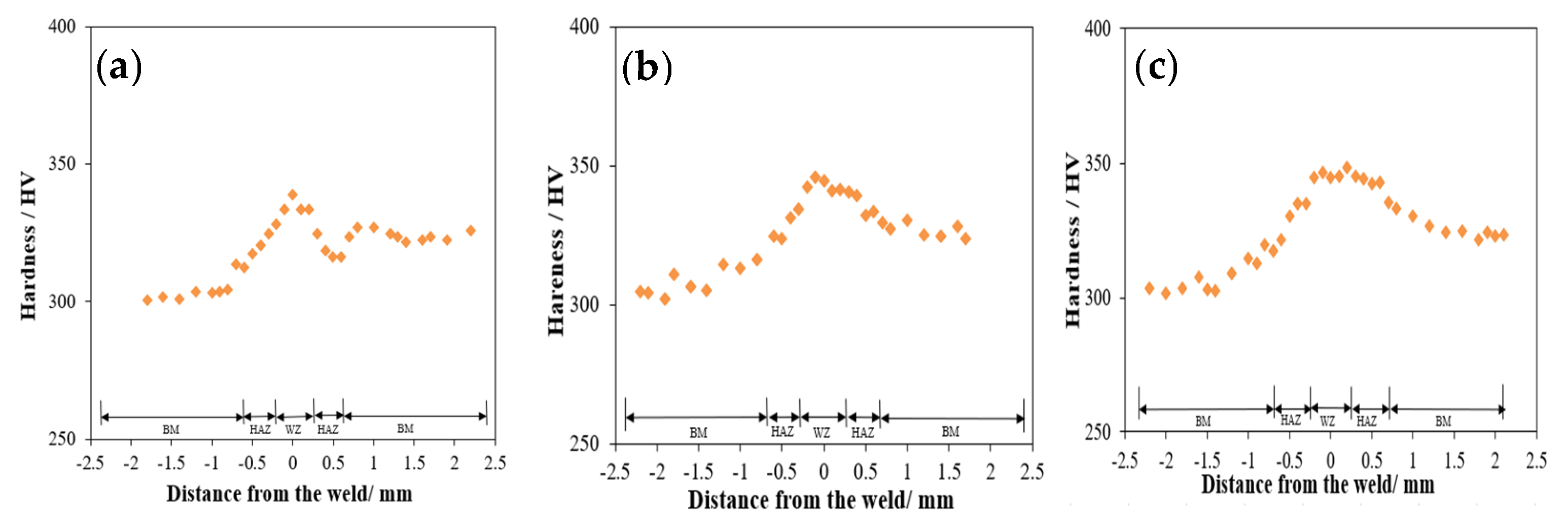
3.5. Microhardness of the Joint

Figure 17 shows the distribution of microhardness of the joint at different friction pressures. It found that the hardness of the base metal on the rotating side with equiaxial structure is lower than that of the base metal on the fixed side with a lamellar structure as shown in Figure 2.
At the friction pressure of 45 MPa, the hardness of the weld zone is between 330–350 HV, and it is the highest, which is about 6% higher than that of the base metal. As mentioned above, the martensite is observed at the weld zone as shown in Figure 6, so the hardness of the weld zone is higher than base metal. The hardness of the thermal mechanically affected zone on both sides decreases with increasing the distance from the WZ.
As the friction pressure increases to 55 MPa or 65 MPa, the hardness of the weld zone is almost the same as that of the friction pressure of 45 MPa. The hardness of the thermal mechanically affected zone on both sides also decreases. Wang et al. [13] found a similar phenomenon for the microstructure and characteristics of the TC11 joint welded by. With the increase of friction pressure, the hardness has no obvious change.

4. Conclusions

The C400 continuous drive friction welding machine was used to connect TC4 titanium alloy tubes with a diameter of 73 mm and a wall thickness of 9 mm. Different friction pressures were used to weld the pipes. After the welding, the joints were evaluated using a metallographic microscope and a microhardness tester. The following conclusions have been obtained.
(1)
The joints do not exhibit any defects such as pores or cracks in the current welding parameters. The quality of the joints is good.
(2)
As the friction pressure increases, the size of the flash morphology also increases, while the width of the weld zone decreases.
(3)
In weld zone and flash, martensite has no obvious change with the increase of friction pressure.
(4)
The proportion of LAGB in the joint decreases, which indicates that friction pressure has a certain influence on the microstructure.
(5)
With the increase of friction pressure, the recrystallization is sufficient, but when the pressure is high, the deformation dominates in the joint.
(6)
The hardness of the weld zone is slightly higher than that of the base metal on both sides. The hardness of the thermal mechanically affected zone on both sides decreases with increasing the distance from the WZ. With the increase of friction pressure, the hardness doesn’t change significantly.

Author Contributions

Conceptualization, S.C. and S.W.; Methodology, S.W. and W.Q.; Software, Y.Z.; Validation, Y.Z.; Investigation, G.W.; Writing—original draft, S.C. and G.W.; Writing—review & editing, W.Q.; Supervision, W.Q. All authors have read and agreed to the published version of the manuscript.

Funding

The authors thank the financial support of the National Natural Science Foundation of China (No.52271045, No. 52075551) and the Key Research and Development Program of Shanxi Province (No. 2022GY-224).

Data Availability Statement

Data will be made available on request.

Conflicts of Interest

Author Yiqiang Zhangwas employed by the company CNPC Baoji Petroleum Pipe Industry Co., Ltd. The remaining authors declare that the research was conducted in the absence of any commercial or financial relationships that could be construed as a potential conflict of interest.

References

  1. Zhang, W.D.; Huang, Y.; Wu, J.; Shi, T.H.; Zhang, Q.; Zhang, Z.S.; Yu, H.R. Performance Test of Weld Zone of Rotary Friction Welding of Titanium Alloy Drill Pipe. J. Phys. 2023, 3, 2587. [Google Scholar] [CrossRef]
  2. Zhao, Z.P.; Ma, T.J.; Li, W.Y.; Zhang, Y. The influence of welding pressure on the microstructure and properties of linear friction welded joints of TB2 titanium alloy. Weld. Pipe 2019, 11, 004. [Google Scholar]
  3. Zhang, X.Y.; Liu, T.; Geng, J.Y. Research on Friction Stir Welding Process and Properties of 7075 Aluminum Alloy. Spec. Cast. Non-Ferr. Alloys 2024, 8, 1114–1118. [Google Scholar]
  4. Xi, J.H.; Ge, P.; Hou, P. Continuous drive friction welding for the preparation of titanium alloy pipe fittings. Welding 2020, 9, 47–51+64. [Google Scholar]
  5. Cheng, P.X.; Xi, J.H.; Liu, J.; Shi, L.C.; Zhang, J.J. Microstructure and properties of inertial friction welded joint of TA18 titanium alloy tube. Steel Vanadium Titan. 2024, 6, 74–79. [Google Scholar]
  6. Chang, C.C.; Li, J.; Cui, Y. Microstructure and properties analysis of TC21 titanium alloy linear friction welded joint. Rare Metal Mater. Eng. 2022, 10, 3843–3849. [Google Scholar]
  7. Du, S.G.; Liu, G.X.; Chen, H. Microstructure and texture evolution of TC17(α+β)/TC17(β) linear friction welding process. J. Mech. Eng. 2024, 2, 99–106. [Google Scholar]
  8. Wu, Y.Q.; Zhou, J.; Zhang, C.B. Microstructure, fracture toughness and crack propagation characteristics of TC4 titanium alloy inertia friction joint. Rare Met. Mater. Eng. 2023, 9, 3032–3138. [Google Scholar]
  9. Gao, S.; Yuan, M.Q. Study on microstructure and properties of Ti60/TC17 dissimilar titanium alloy inertial friction welding joint. Electr. Weld. Mach. 2023, 8, 115–121+143. [Google Scholar]
  10. Amirov, A.I.; Chumaevskii, A.V.; Utyaganova, V.R.; Gusarova, A.V.; Gurianov, D.A.; Rubtsov, V.E.; Kolubaev, E.A. Structure and Properties of Dissimilar Joint of Ti and Al Alloys Obtained by Friction Stir Welding. Russ. Phys. J. 2023, 66, 970–977. [Google Scholar] [CrossRef]
  11. Morgane, G.; Fènoël, A.N.M.; Vidal, V.; Farhad, R.A.; Christine, B. Multi-scale effects of the tool shape and length on the interfacial microstructure and the mechanical behaviour of Al2024/Ti-6Al-4V lap friction stir welds. J. Manuf. Process. 2024, 113, 360–372. [Google Scholar]
  12. Yang, X.W.; Yao, M.X.; Su, Y.; Meng, T.X.; Ma, S.T.; Guo, Z.G.; Li, W.Y. Forming control and the relationship between microstructure and mechanical property in TIG-assisted friction stir welded joint of Ti-6Al-3Nb-2Zr-1Mo titanium alloy. J. Mater. Res. Technol. 2024, 33, 6196–6206. [Google Scholar] [CrossRef]
  13. Guo, Z.G.; Ma, T.J.; Chen, T.; Wang, J.T.; Chen, X.; Yang, X.W.; Vairis, A. Linear friction welding of equiaxed Ti17 titanium alloy: Effects of microstructure evolution on tensile and impact properties. J. Mater. Sci. 2024, 24, 10189–10200. [Google Scholar] [CrossRef]
  14. Gong, H.; Liu, M.Q.; Zhang, T.; He, Y.B.; Wu, Y.X.; Yu, Z.X. Study on Residual Stress and Optimization of Welding Parameters in Linear Friction Welding of TC17 Titanium Alloy. Materials 2022, 24, 8963. [Google Scholar] [CrossRef]
  15. Wang, X.Y.; Quan, Y.Z.; Li, J.; Tao, J.; Li, J.; Li, W.Y. Structure and texture evolution mechanism of TC11 titanium alloy linear friction welding joint. Rare Met. 2023, 5, 692–700. [Google Scholar]
  16. Lu, Y.; Yuan, K.; Yang, X.; Ding, Y.; Sun, F.X.; Wang, R.H. Effect of friction pressure on the performance of Super304H/T92 friction welded joints. Mater. Rep. 2016, 30, 494–498. [Google Scholar]
  17. Wen, G.D. Study on the macroscopic deformation and micromorphology of Ti and Fe continuously driven friction weld welding interfaces. Hot Work. Process 2019, 11, 24–27+31.14. [Google Scholar]
  18. Guo, Z.G.; Ma, T.J.; Li, J.; Li, W.Y.; Liu, Y.S. Effect of friction pressure on the microstructure of Ti17 titanium alloy linear friction welding joint. Hot Work. Process 2023, 21, 77–81. [Google Scholar]
  19. Wang, S.Q.; Jing, K.; Wen, G.D.; Li, X.; Li, Y.B. Study on the effect of friction time on the structure and properties of drill pipe joints. Hot Work. Process 2017, 3, 192–194. [Google Scholar]
  20. Meng, T.X.; Yang, X.W.; Su, Y.; Ma, S.T.; Ma, H.Y.; Guo, Z.G.; Guo, W.Y. Formation mechanism and failure behavior in synergistic double-sided probeless friction stir spot welded joints of 6061 aluminum alloy. Mater. Charact. 2024, 219, 114631. [Google Scholar] [CrossRef]
  21. Guo, Z.G.; Ma, T.J.; Li, W.Y.; Zhang, Y.; Zhao, Z.P.; Tao, J.; Kang, W.J. Intergrowth bonding mechanism and mechanical property of linear friction welded dissimilar near-Alpha to near-Beta titanium alloy joint. Adv. Eng. Mater. 2021, 5, 2001479. [Google Scholar] [CrossRef]
  22. Ali, Y. The Effect of Different Friction Pressure on the Microstructural and Mechanical Properties of Ti Gr2 Titanium Alloy. J. Mater. Eng. Perform. 2023, 19, 8678–8686. [Google Scholar]
  23. Xiao, X.; Mao, Y.; Qin, D.Q.; Wang, X.C.; Fu, L. Effects of microstrcture composition and orientation on micro mechanical properties of linear friction welding joint weld zone for heteromorphic TC17 titanium alloy. J. Mater. Sci. 2023, 41, 16208–16224. [Google Scholar] [CrossRef]
  24. Dai, Z.K. Study on the structure and properties of laser welding joint with spatial structure of TA15 titanium alloy. Master’s Thesis, Nanchang Hangkong University, Nanchang, China, 2023. [Google Scholar]
Figure 1. The macroscopic morphology of the joint.
Alloys 04 00004 g001
Figure 2. Microstructure of base metal (a) the rotating side, (b) the fixed side.
Alloys 04 00004 g002
Figure 3. Flash of 45 MPa (a) the rotating side, (b) center, and (c) the fixed side.
Alloys 04 00004 g003
Figure 4. Flash of 55 MPa (a) the rotating side, (b) center, and (c) the fixed side.
Alloys 04 00004 g004
Figure 5. Flash of 65 MPa (a) the rotating side, (b) center, and (c) the fixed side.
Alloys 04 00004 g005
Figure 6. Microstructure of the 45 MPa (a) macrography (b) the thermal mechanically affected zone at the rotating side, (c) weld zone, and (d) the thermal mechanically affected zone at the fixed side.
Alloys 04 00004 g006
Figure 7. Microstructure of the 55 MPa (a) macrography (b) the thermal mechanically affected zone at the rotating side, (c) weld zone, and (d) the thermal mechanically affected zone at the fixed side.
Alloys 04 00004 g007
Figure 8. Microstructure of the 65 MPa (a) macrography (b) the thermal mechanically affected zone at the rotating side, (c) weld zone, and (d) the thermal mechanically affected zone at the fixed side.
Alloys 04 00004 g008
Figure 9. 45 MPa results (a) IPF, (b) grain size, (c) phase, (d) misorientation angle.
Alloys 04 00004 g009aAlloys 04 00004 g009b
Figure 10. 55 MPa results (a) IPF, (b) grain size, (c) phase, (d) misorientation angle.
Alloys 04 00004 g010
Figure 11. 65 MPa results (a) IPF, (b) grain size, (c) Phase, (d) misorientation angle.
Alloys 04 00004 g011
Figure 12. 45 MPa results (a) recrystallization distribution, (b) fraction.
Alloys 04 00004 g012
Figure 13. 55 MPa results (a) recrystallization distribution, (b) fraction.
Alloys 04 00004 g013
Figure 14. 65 MPa results (a) recrystallization distribution (b) fraction.
Alloys 04 00004 g014
Figure 15. GND (a) 45 MPa, (b) 55 MPa, (c) 65 MPa.
Alloys 04 00004 g015
Figure 16. Pole figures (a) 45 MPa, (b) 55 MPa, (c) 65 MPa.
Alloys 04 00004 g016
Figure 17. Microhardness (a) 45 MPa, (b) 55 MPa, (c) 65 MPa.
Alloys 04 00004 g017
Table 1. Continuous Drive Friction Welding Parameters.
Specimen NumberFriction Pressure/MPaRotation Speed/rpmUpsetting Force/MPaFriction Shortening/mm
NO. 1451311809
NO. 2551311809
NO. 3651311809
Disclaimer/Publisher’s Note: The statements, opinions and data contained in all publications are solely those of the individual author(s) and contributor(s) and not of MDPI and/or the editor(s). MDPI and/or the editor(s) disclaim responsibility for any injury to people or property resulting from any ideas, methods, instructions or products referred to in the content.

