2.1. Geometric Design of the Blade
In the present study, a custom wind turbine blade was designed based on the NACA 4412 airfoil profile, which was used as the reference cross-sectional geometry along the blade span. The blade geometry was generated by varying the chord length and progressively rotating the airfoil cross-sections from the root to the tip, with a total twist angle of 15° over the blade span, to provide a suitable aerodynamic and structural configuration. The blade has a total length of 100 cm, with the first 10 cm forming the neck section, which serves as the interface for attachment to the turbine rotor or hub. The remaining 90 cm, extending toward the tip, is divided into nine equal segments of 10 cm each.
The NACA 4412 airfoil was selected as the reference cross-sectional profile for the blade design due to its well-established use in wind turbine and aerodynamic applications and the availability of reliable geometric data and previous studies in the literature. The airfoil coordinates were obtained from a publicly available airfoil database and used to generate the blade cross-sections. The NACA 4412 profile itself was maintained along the blade span; however, the cross-sectional geometry was scaled according to the spanwise chord distribution and progressively rotated to introduce the prescribed twist angle. Therefore, the custom blade developed in this study does not represent a uniform NACA 4412 extrusion. Instead, it is a three-dimensional blade geometry generated from the NACA 4412 reference profile through spanwise scaling and rotation, with the chord length and twist angle varying from the root toward the tip, as specified in
Table 1.
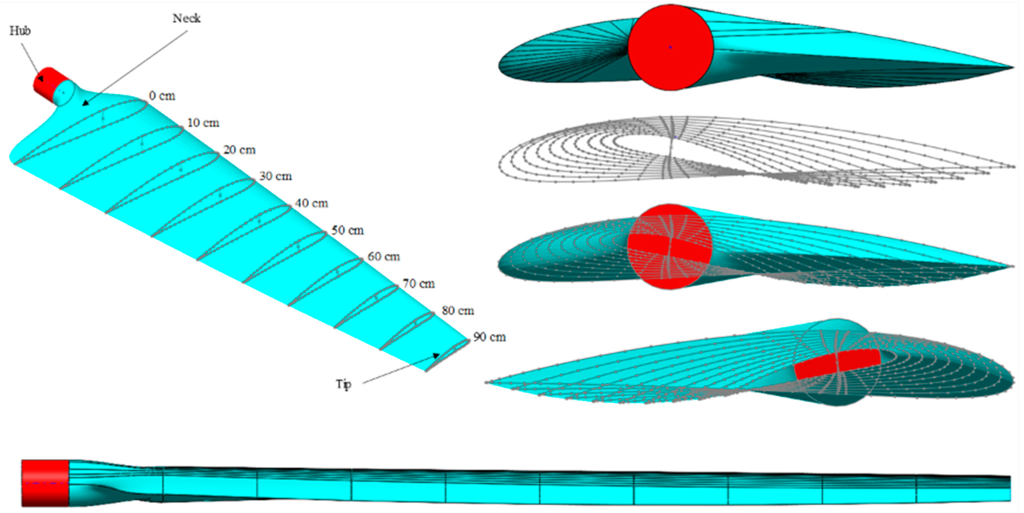
The wind turbine blade was designed via SolidWorks 2025, and the resulting geometry is illustrated in
Figure 1. As shown, the blade consists of several distinct parts, including the shell, neck, root, tip, and hub.
2.2. Material Properties and Layup Configuration
In the present study, the blade structure utilized a unidirectional GFRP composite with an epoxy resin matrix. Compared with woven fabrics, the glass fibers used are unidirectional, with an area weight of 400 g/m
2, which is selected for its superior tensile properties, high stiffness in the fiber direction, and favorable handling during manufacturing. This choice also offers a better strength-to-weight ratio and more predictable mechanical behavior under uniaxial loading, making it particularly suitable for the primary load-bearing regions of the blade. The mechanical properties of the epoxy resin and the glass fibers are summarized in
Table 2.
To define the composite lamina in ANSYS ACP, the homogenized orthotropic material properties were obtained using ANSYS Material Designer. In this approach, the constituent properties of dry glass fiber and epoxy resin were introduced at the microscale, and a representative volume element was generated to evaluate the equivalent lamina properties. A fiber volume fraction of
was assumed, which is consistent with the resin infusion manufacturing route adopted in this study. The homogenization process provided the effective orthotropic engineering constants required for finite element modeling, including the elastic moduli, shear modulus, Poisson’s ratio, and density. These equivalent lamina properties were then directly imported into the ANSYS ACP module for structural analysis. The resulting homogenized properties are listed in
Table 3.
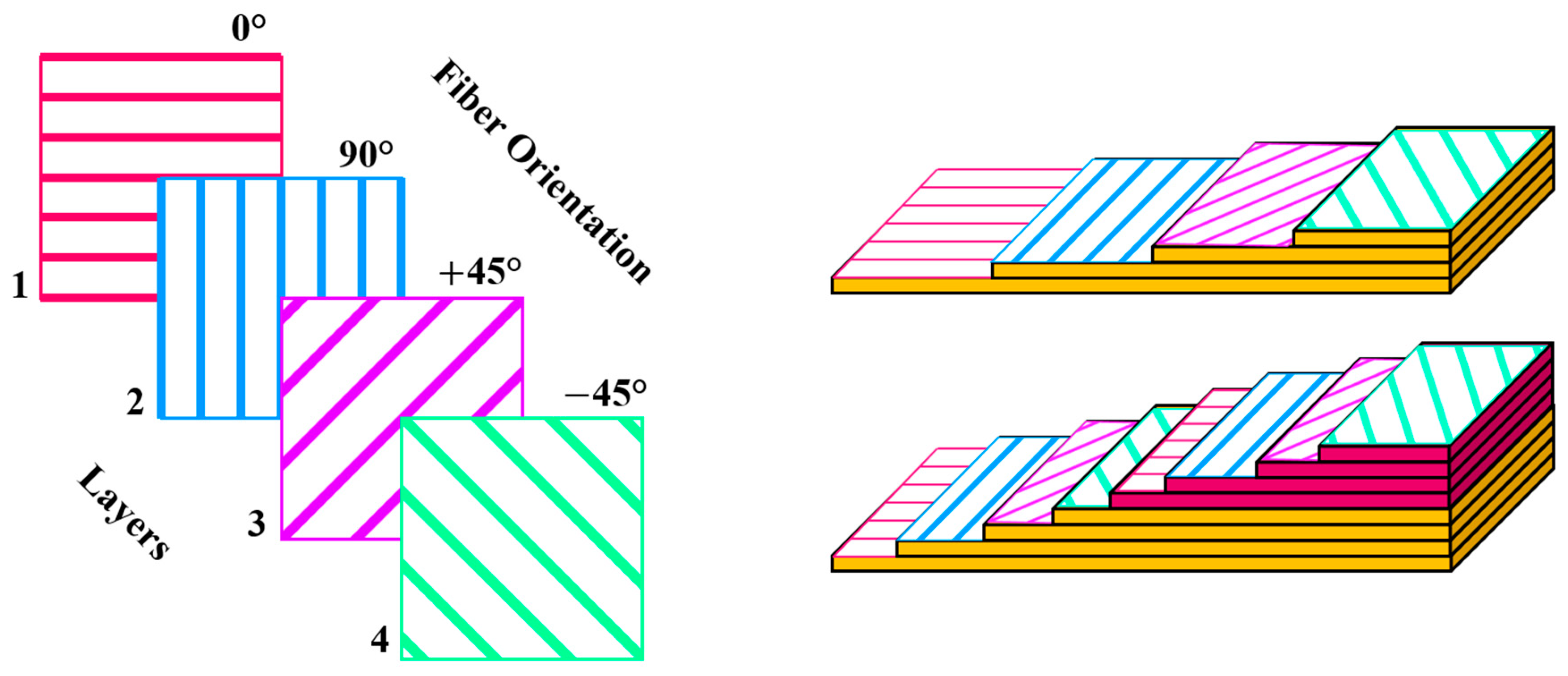
The stacking sequence of composite laminates plays a critical role in determining their mechanical performance, including stiffness, strength, and resistance to different loading conditions. By strategically orienting fibers in different directions, laminates can be personalized to carry loads under multiple loading conditions and improve structural stability under complex stress states. This study incorporates a 15° pre-twist and a specific stacking sequence (0°, 90°, +45°, and −45° as showed in
Figure 2) as fixed design parameters to model a realistic turbine blade, while the optimization focuses on the influence of load conditions and the number of laminate layers. This configuration was selected based on the expected loading behavior of the blade, where the 0° and 90° layers primarily contribute to resistance against bending and axial loading, while the +45° and −45° layers contribute to torsional stiffness and resistance to shear and twisting. Four laminate configurations were investigated, consisting of 1, 2, 3, and 4 repetitions of this sequence, corresponding to total layer counts of 4, 8, 12, and 16 layers, respectively. The effect of increasing the number of laminate layers on the structural stiffness and dynamic response was subsequently evaluated through experimental tensile testing, finite element analysis, and modal and harmonic response analyses.
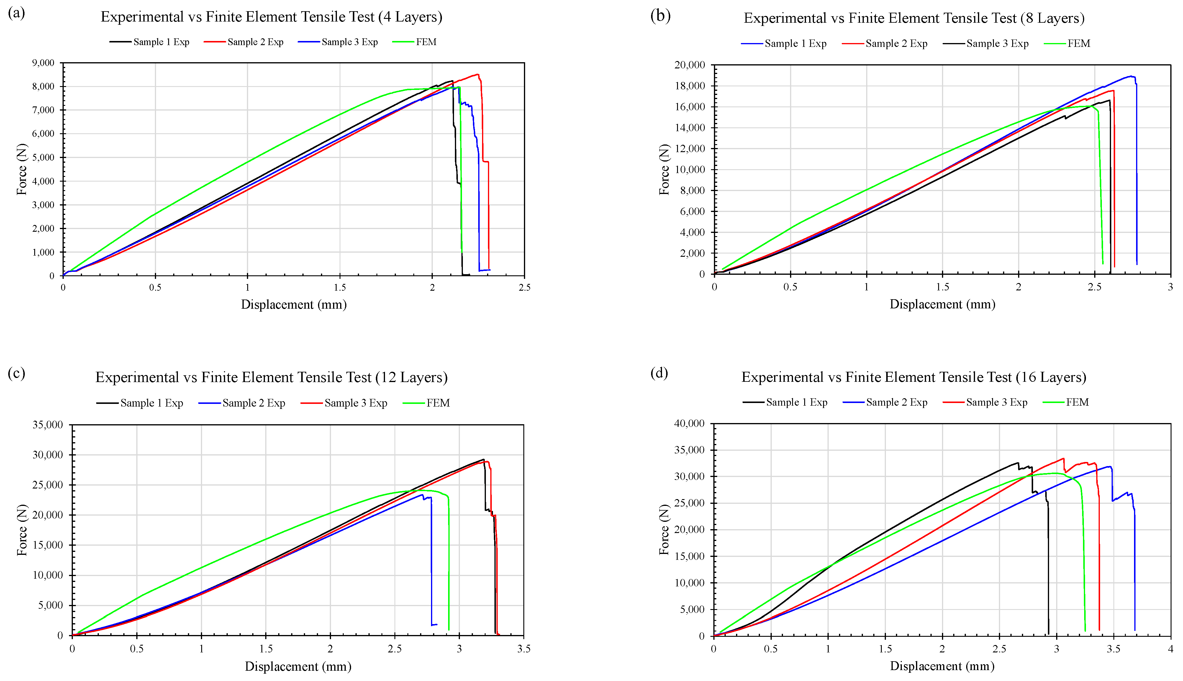
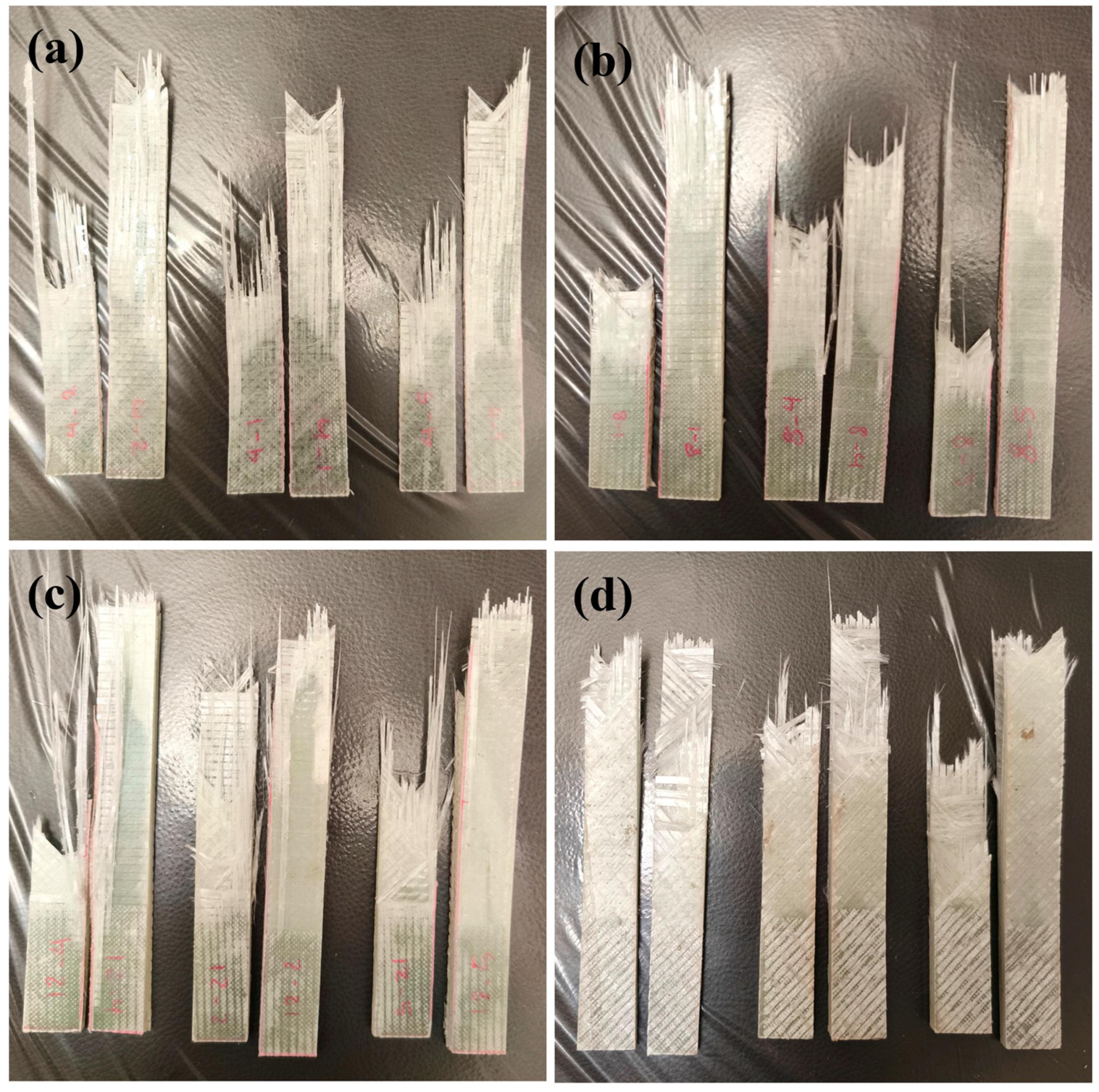
For each laminate configuration, three specimens were fabricated using the same layup pattern to ensure repeatability and reliability of the experimental measurements. The specimens were subjected to uniaxial tensile testing using a 5-ton universal testing machine in accordance with ASTM D3039, a standard test method for determining the tensile properties of polymer matrix composite materials reinforced with high-strength fibers. The test specimens had dimensions of 200 mm × 20 mm, with the thickness varying according to the number of composite layers. During testing, 50 mm of each specimen at both ends was clamped using aluminum grips, leaving a 100 mm gauge length between the grips. The tensile tests were conducted at a crosshead speed of 20 mm/min. The experimental force–displacement responses obtained from the three specimens for each laminate configuration were recorded and subsequently used for comparison with the corresponding finite element simulation results to validate the numerical model.
The selected material system and layup configuration were designed to provide a suitable balance between stiffness, strength, and weight for the composite blade. The influence of the laminate configuration on these structural characteristics was subsequently assessed through the experimental and numerical analyses presented in the following sections.
2.3. Finite Element Model Setup
The numerical analysis was conducted using a sequential finite element framework to evaluate the structural and dynamic response of the composite wind turbine blade and to identify an optimized configuration. The overall numerical procedure consisted of four main stages: (1) development of the composite blade model and definition of the laminate layup in ANSYS ACP, (2) modal analysis to determine the natural frequencies and corresponding mode shapes, (3) harmonic response analysis to evaluate the blade response under the loading conditions defined by the Design of Experiments (DOE), and (4) multi-objective optimization based on the obtained structural response parameters. The main engineering response parameters considered in the numerical analyses were the maximum stress and maximum tip displacement, while the failure index (FI) was subsequently considered as an additional criterion in the optimization process. This framework was used to investigate the effects of the number of composite layers, force magnitude, and force application distance on the dynamic structural performance of the blade.
To evaluate the structural response of the wind turbine blade under aerodynamic and harmonic loading, a finite element model was developed via ANSYS Workbench integrated with the ACP (Ansys Composite pre-post) module.
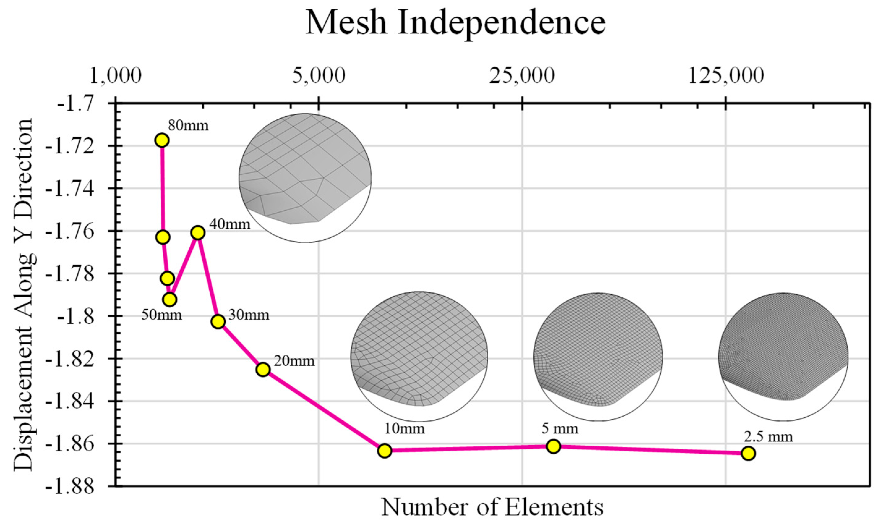
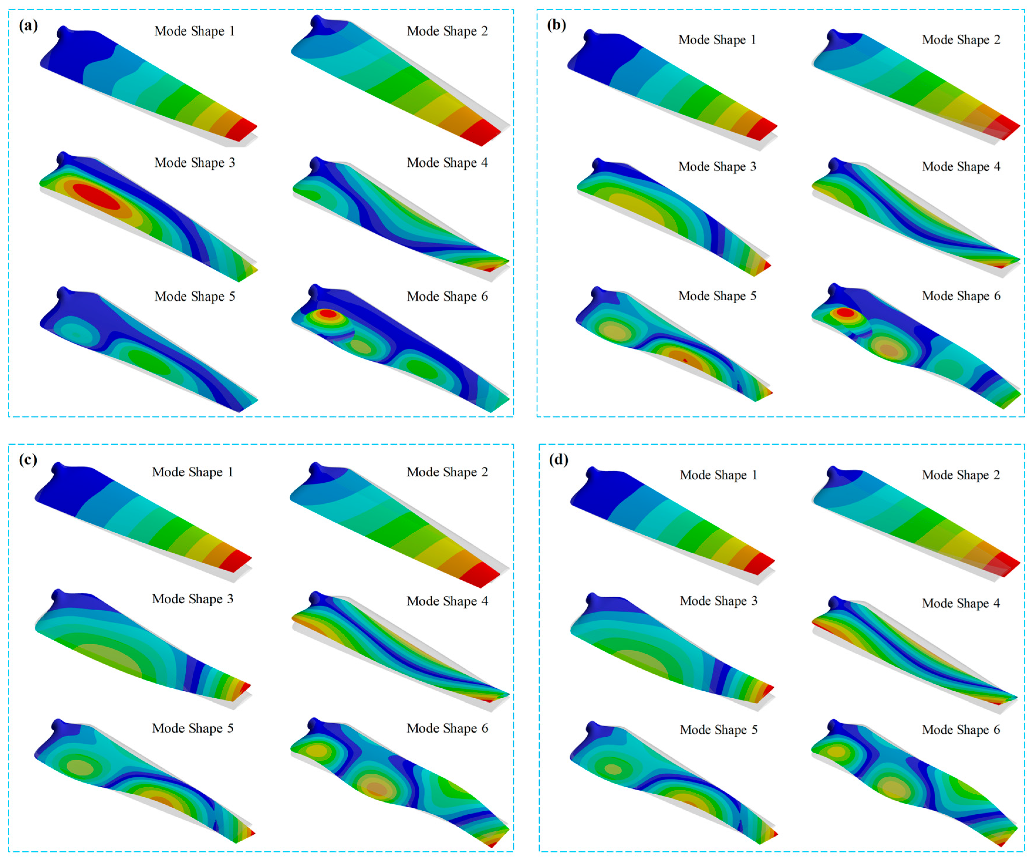
The blade geometry, initially designed in SolidWorks, was imported into the ANSYS Workbench environment for meshing and structural analysis. To enhance accuracy in the critical connection region between the blade and the aluminum hub, a refined mesh was applied using the contact region feature, with a local element size of 5 mm. In the ANSYS ACP Pre environment, the composite blade was modeled via layup sets consisting of 4, 8, 12, and 16 layers, following the orientation sequence of 0°, 90°, +45°, and −45°, respectively. In the modal analysis setup within ANSYS, six fundamental mode shapes were targeted, and the solver was configured to extract the first six natural frequencies. A fixed support boundary condition was applied at the blade root, representing the connection point to the turbine hub. Once the boundary conditions and composite layup were defined, modal analysis was executed to obtain the natural frequencies and corresponding deformation modes.
In this study, DOE was employed to investigate the influence of the layer count, applied load magnitude, and load position on the structural response of the composite blade, enabling a more informed and optimized design process. The first input parameter considered in the DOE is the magnitude of the applied force. On the basis of the specific geometry of the blade, the following
force levels were selected: 15 N, 22.5 N, 30 N, and 37.5 N. The second input parameter, referred to as
force distance, represents the location at which the external force is applied along the blade span. To capture the influence of the load position on the structural response, four levels were defined: 0 cm, 30 cm, 60 cm, and 90 cm from the blade root. The third input parameter is the
number of layers, which is defined at four levels: 4, 8, 12, and 16 layers. Given that the experimental setup involves three input factors, each defined at four levels, the Taguchi method was selected as a suitable approach for designing the experiments. Using the Taguchi method and defining the input parameters within Minitab 18, the experimental design was constructed on the basis of an L16 orthogonal array. The amplitude of the harmonic force and its application location were defined according to the Force and Force Distance parameters specified in the DOE matrix presented in
Table 4.
The designed experiments were developed specifically for implementation in the harmonic response analysis, ensuring that all simulation conditions align precisely with the defined DOE matrix. Accordingly, 16 simulation trials must be performed in ANSYS to cover all the combinations specified by the Taguchi L16 array.
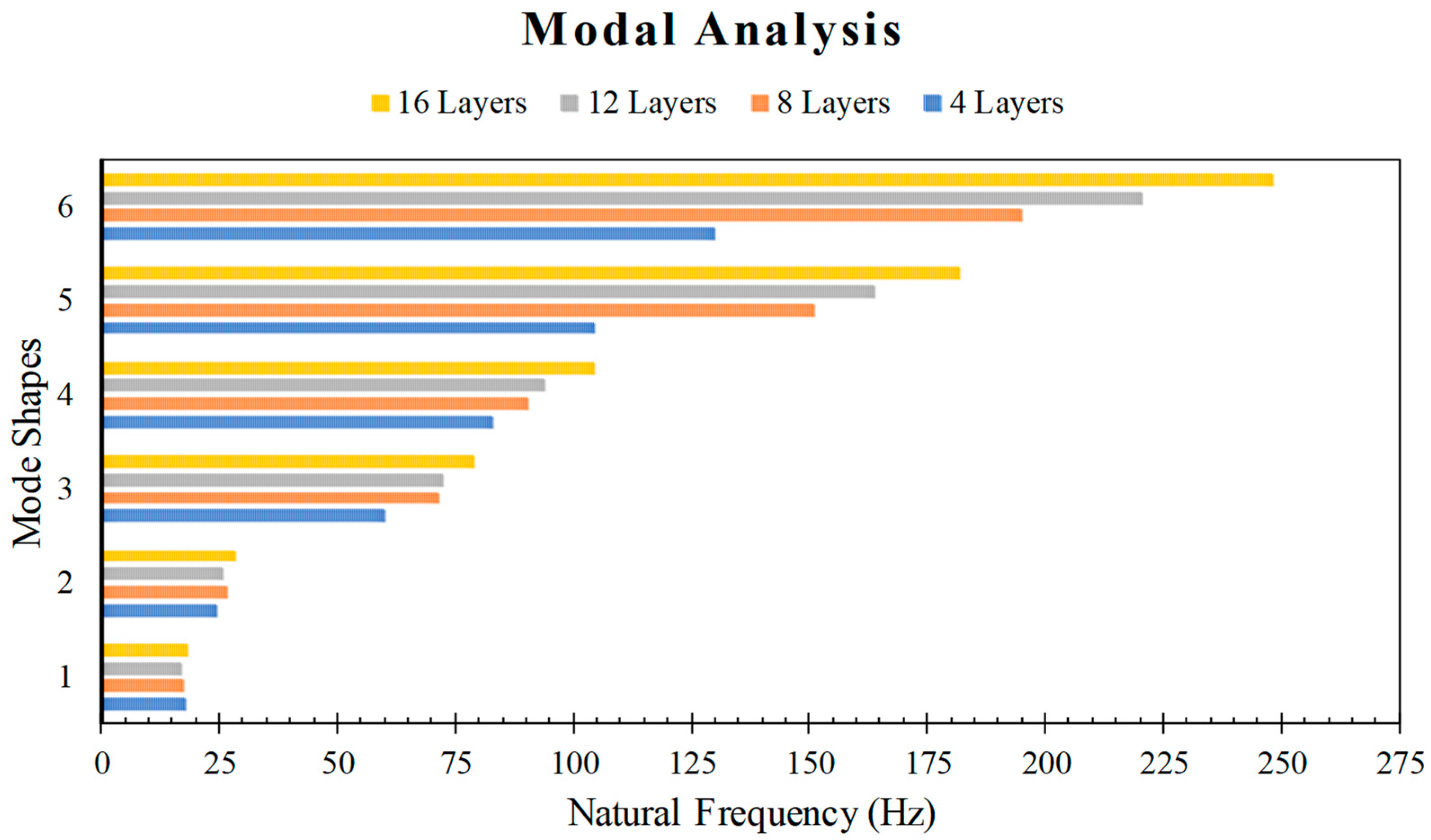
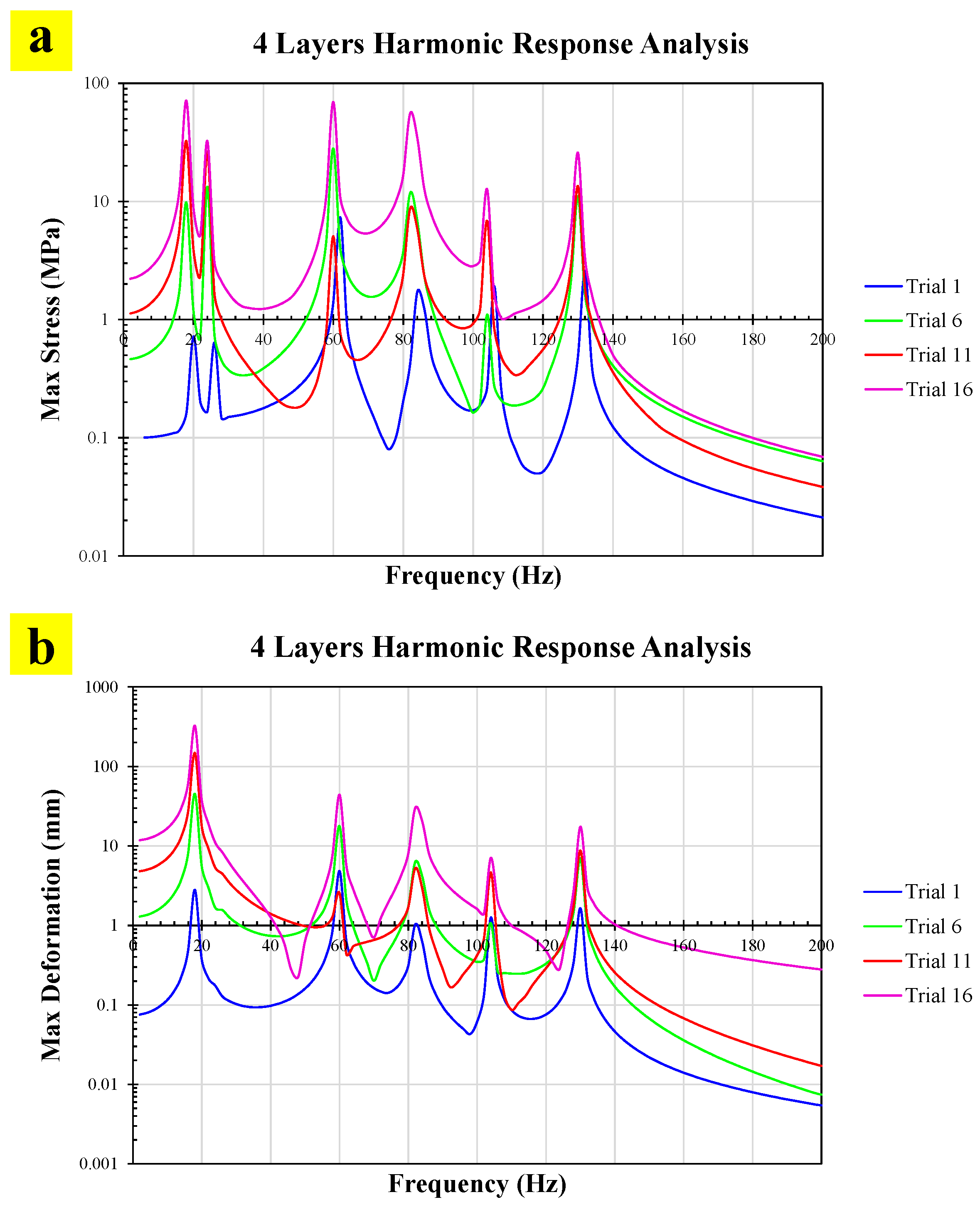
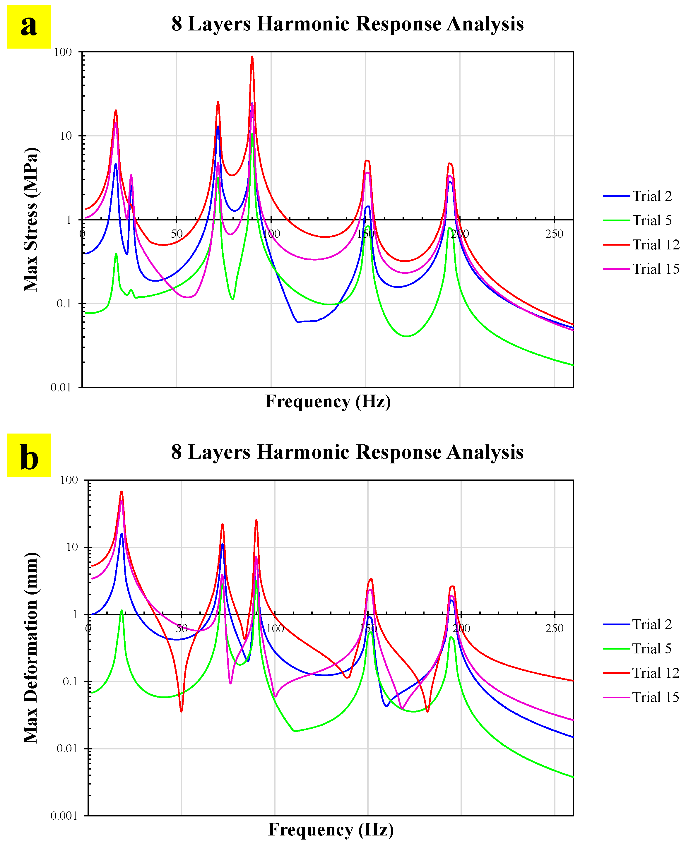
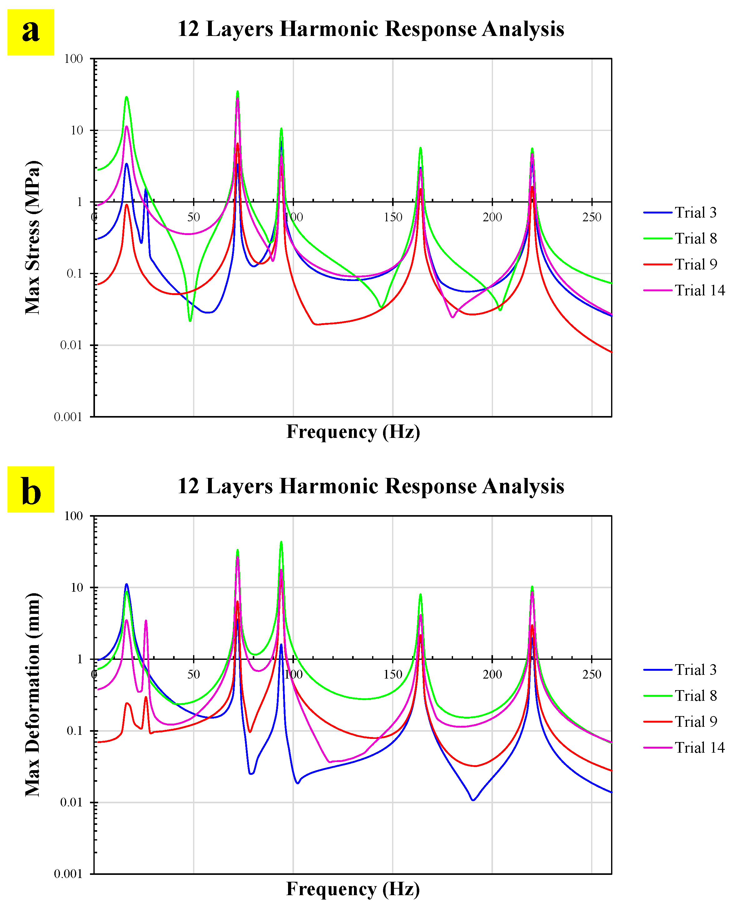
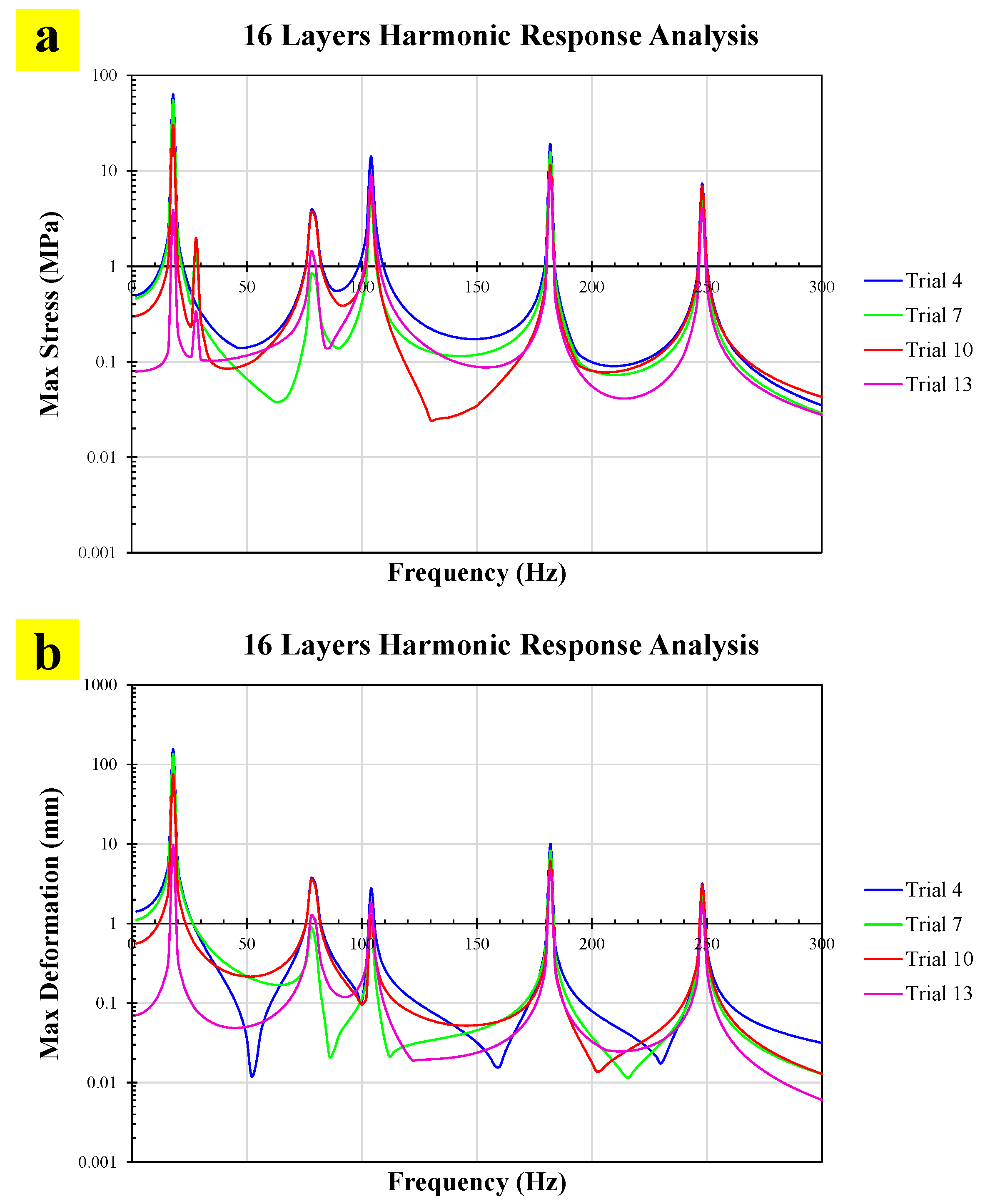
The harmonic response analysis was coupled with the results obtained from the modal analysis and the composite layup defined in ANSYS ACP Pre. The frequency ranges considered for the harmonic loading were selected based on the first six natural frequencies obtained from the modal analysis for each blade configuration. Accordingly, a frequency range of 0–200 Hz was considered for the 4-layer blade, while frequency ranges of 0–250 Hz and 0–300 Hz were considered for the 8- and 12-layer blades and the 16-layer blade, respectively. These frequency ranges were selected to cover the relevant natural frequencies identified from the modal analysis while limiting the computational domain to the frequency range of interest, thereby reducing the computational time and overall analysis cost. In the harmonic response analysis, a constant modal damping ratio of 1% was assumed to account for the inherent damping of the glass/epoxy composite structure. The amplitude of the applied harmonic force and its location were determined based on the DOE results presented in
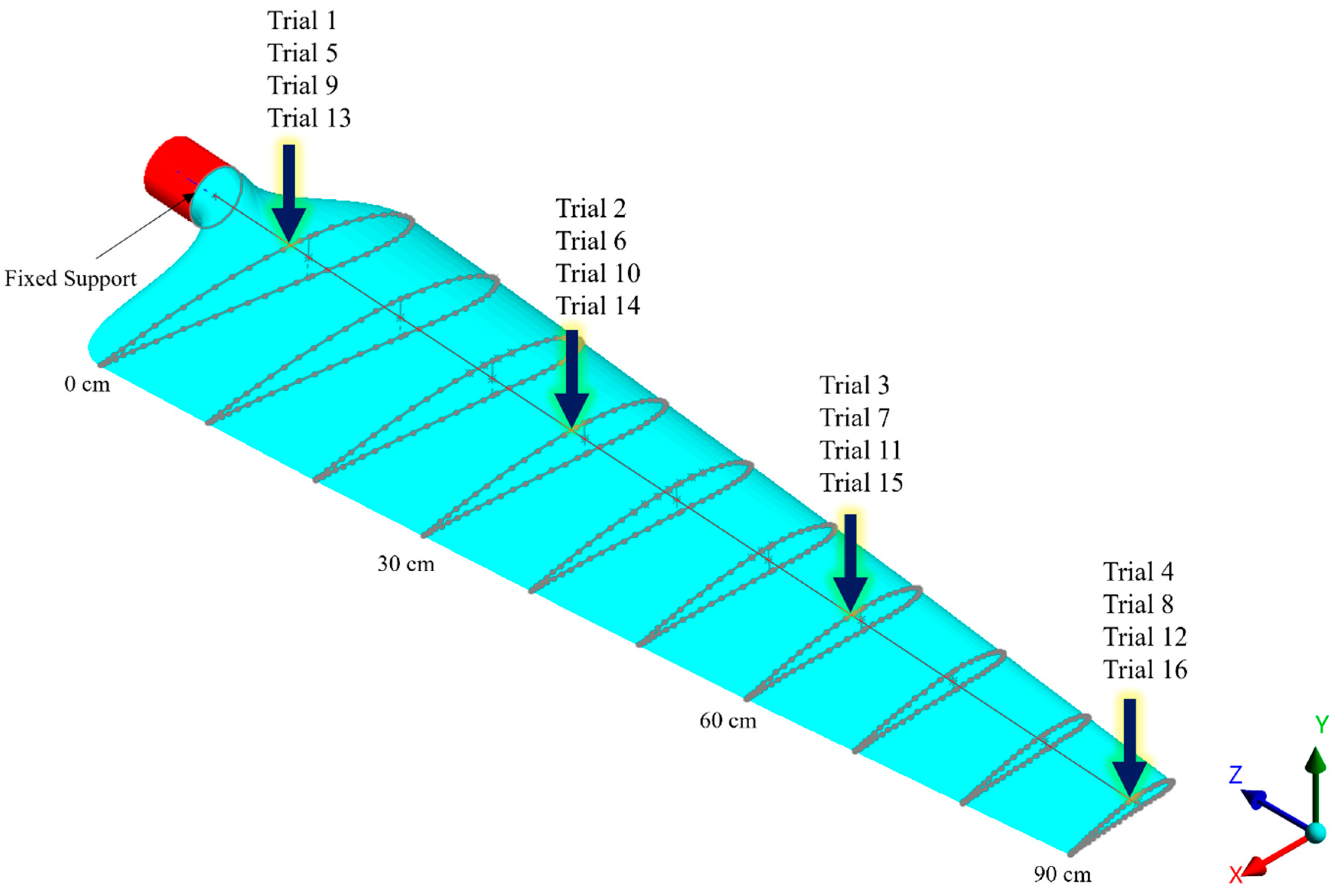
Table 4. The fixed support condition at the blade root, previously defined in the modal setup, was retained. Harmonic loads were applied in the negative Y-direction at various spanwise positions along the blade, as specified by the experimental design. The boundary conditions applied in the harmonic response simulations are illustrated in
Figure 3, in accordance with the Taguchi experimental design.
The primary engineering response parameters (EDPs) extracted from the harmonic response analysis were the maximum stress and maximum tip displacement in the Y-direction. For each simulation trial, the maximum stress over the blade domain was recorded as Max Stress (MPa), while the maximum deformation amplitude at the blade tip in the Y-direction was recorded as Max Displacement (mm). These response parameters were subsequently used to evaluate the dynamic structural performance of the blade and as objective responses in the multi-objective optimization process.
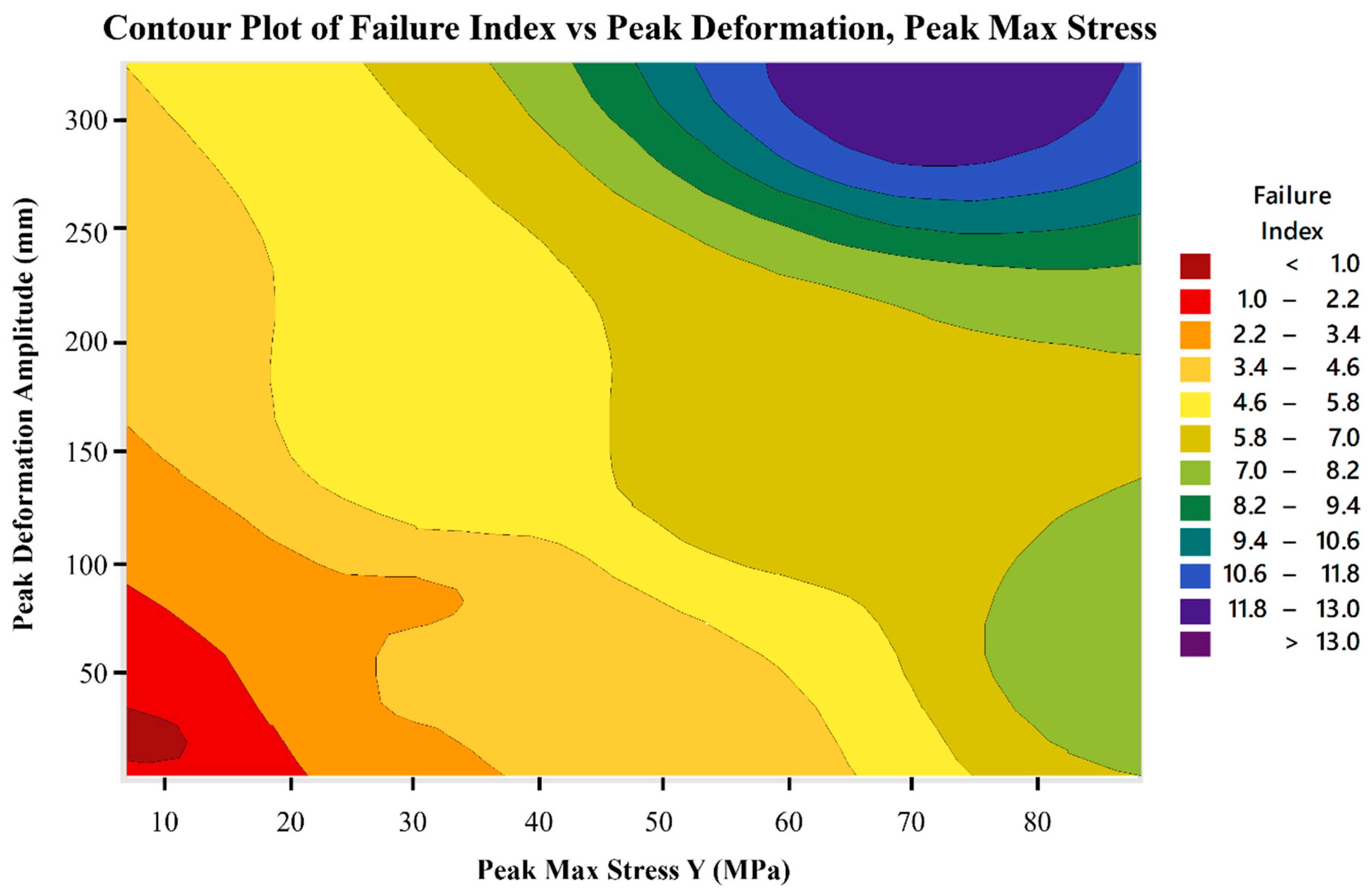
In this study, the failure behavior of the composite blade under dynamic loading was evaluated using the ANSYS ACP Post module. Two failure criteria, namely the Maximum Stress criterion and the Tsai-Wu criterion, were considered to assess the integrity of the composite plies under the applied loading conditions. The FI was used as a quantitative measure of the proximity of the composite material to the corresponding failure criterion. In general, an FI value below 1 indicates that the predicted stress state remains below the defined failure limit, whereas an FI value equal to or greater than 1 indicates that the corresponding failure criterion has been reached or exceeded, respectively. Therefore, lower FI values represent a greater margin from the predicted failure condition and a lower possibility of failure. For each simulation case defined by the DOE matrix, the corresponding maximum FI value was extracted from the ANSYS ACP Post results and recorded as an additional response parameter for the subsequent optimization process.
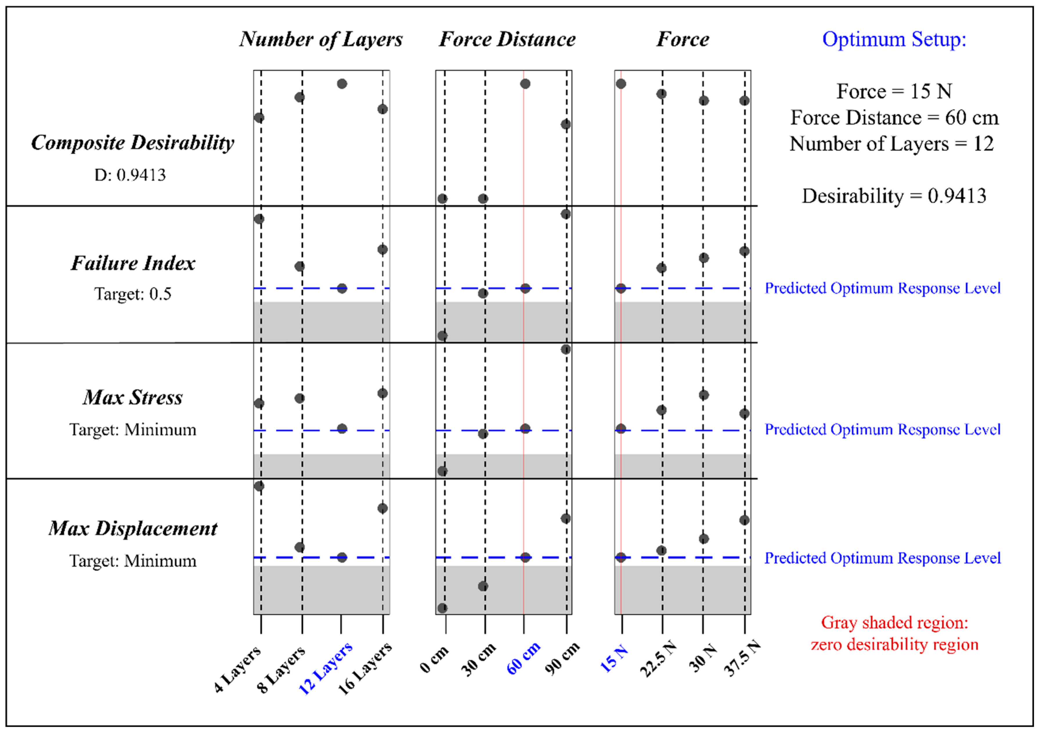
A target FI of 0.5 was selected as a conservative design target, corresponding to a predicted failure index below the critical threshold of 1. This target was selected to maintain a margin from the onset of the predicted failure condition while simultaneously allowing the optimization to achieve low stress and displacement responses. The selection of an intermediate FI target also prevents the optimization from focusing solely on minimizing the FI at the expense of other structural performance criteria.
To identify the most efficient configuration of the composite blade under dynamic loading, a multi-objective optimization process was conducted via Minitab 18.